To my other GT6
pages
November 27, 2020
Closing up the Engine
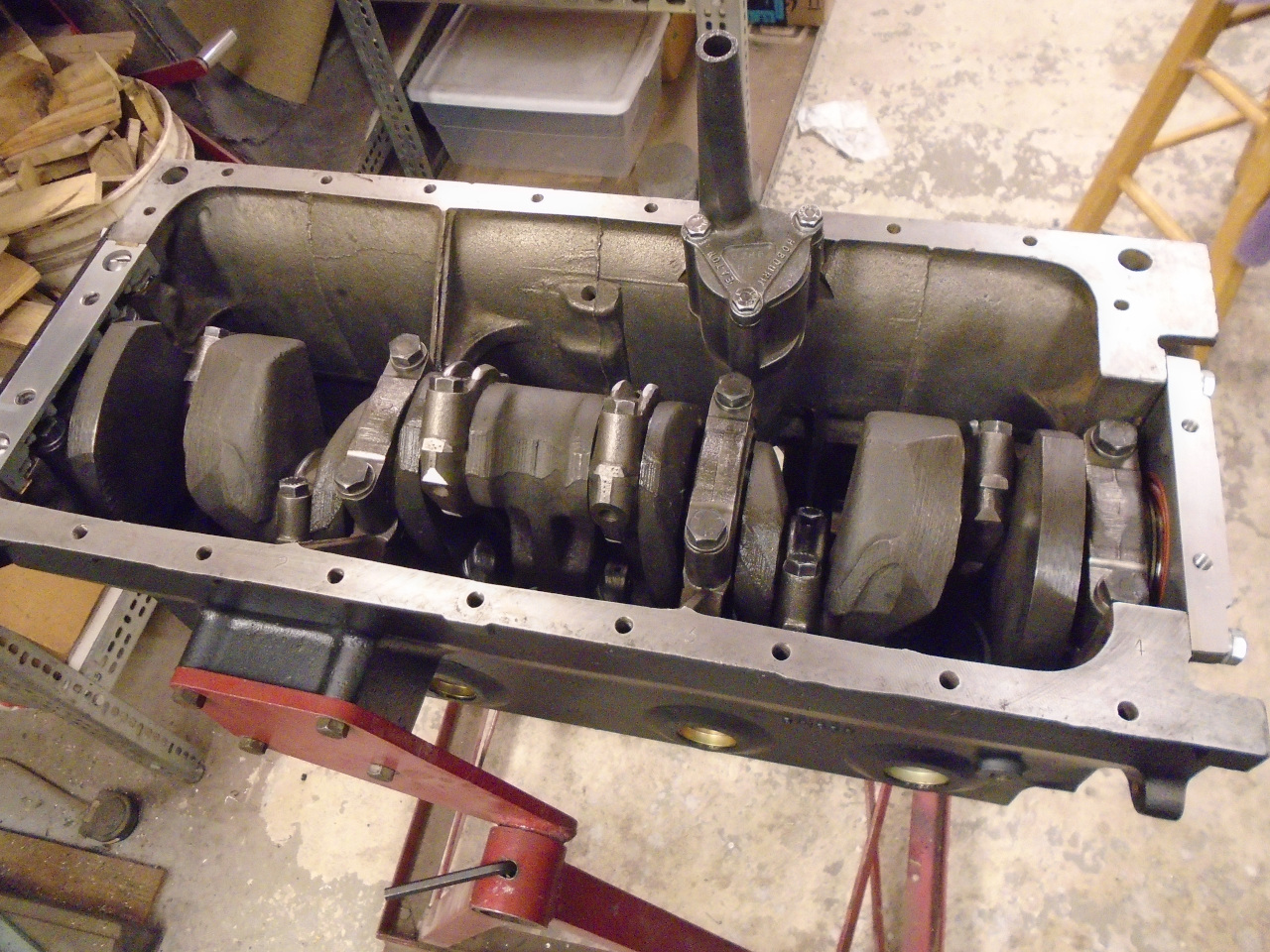
Well, at this point, just about all major internal components of
the engine are done. Crank,
pistons, and rods are installed, and the camshaft is
installed and timed.
One component that still remains is the oil pump. Like most
cars of the era, Triumph used a gerotor type of positive
displacement pump. In this pump, an off-center four lobe
inner rotor drives a five lobe outer rotor. The spaces
between the rotor lobes expand on one side, drawing in oil from
the sump, and contract on the other, sending pressurized oil to
the engine. Containing oil in these spaces depends on fairly
close fitting of the moving parts. Essentially bathed in
oil, these units typically last a long time, but they do wear.


According to my notes, the rotors in this pump were replaced in my
early 80s rebuild, so they are old, but don't have many miles on
them. There are three measurements that assess the pump's
condition: Clearance between the inner and outer rotors,
clearance between the outer rotor and the body, and clearance
between the rotors' ends and the pump's end cap. All
measurements were in spec, but with a caveat. The end
clearance is measured with a straight edge across the body, and
feeler gauges, and this ignores the condition of the end
cap. My end cap had significant scoring. This would
almost certainly make the effective end clearance unacceptable.

The simple remedy was just to linish the cap flat.

So all of the oil pump parts were then ready for reassembly.
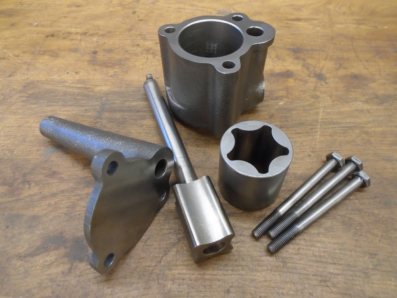
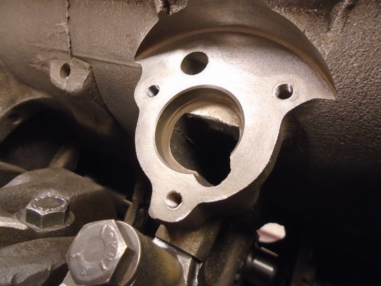
But there was one thing to do to prep the block for the pump
install. The pump drive shaft rides in a removable cast iron
bushing in the block.

I think the factory manual recommends driving the bush in with a
hammer and drift, but since it is pretty brittle, and apparently
hard to source, I wanted a less violent method. This is
pretty much just a rearrangement of parts used to pull the bush
out. Tightening the nuts eases the bushing home.

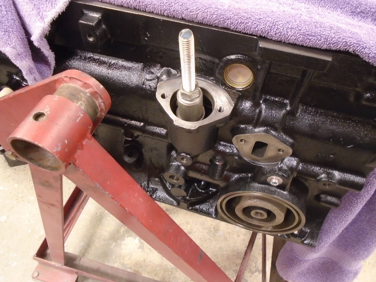

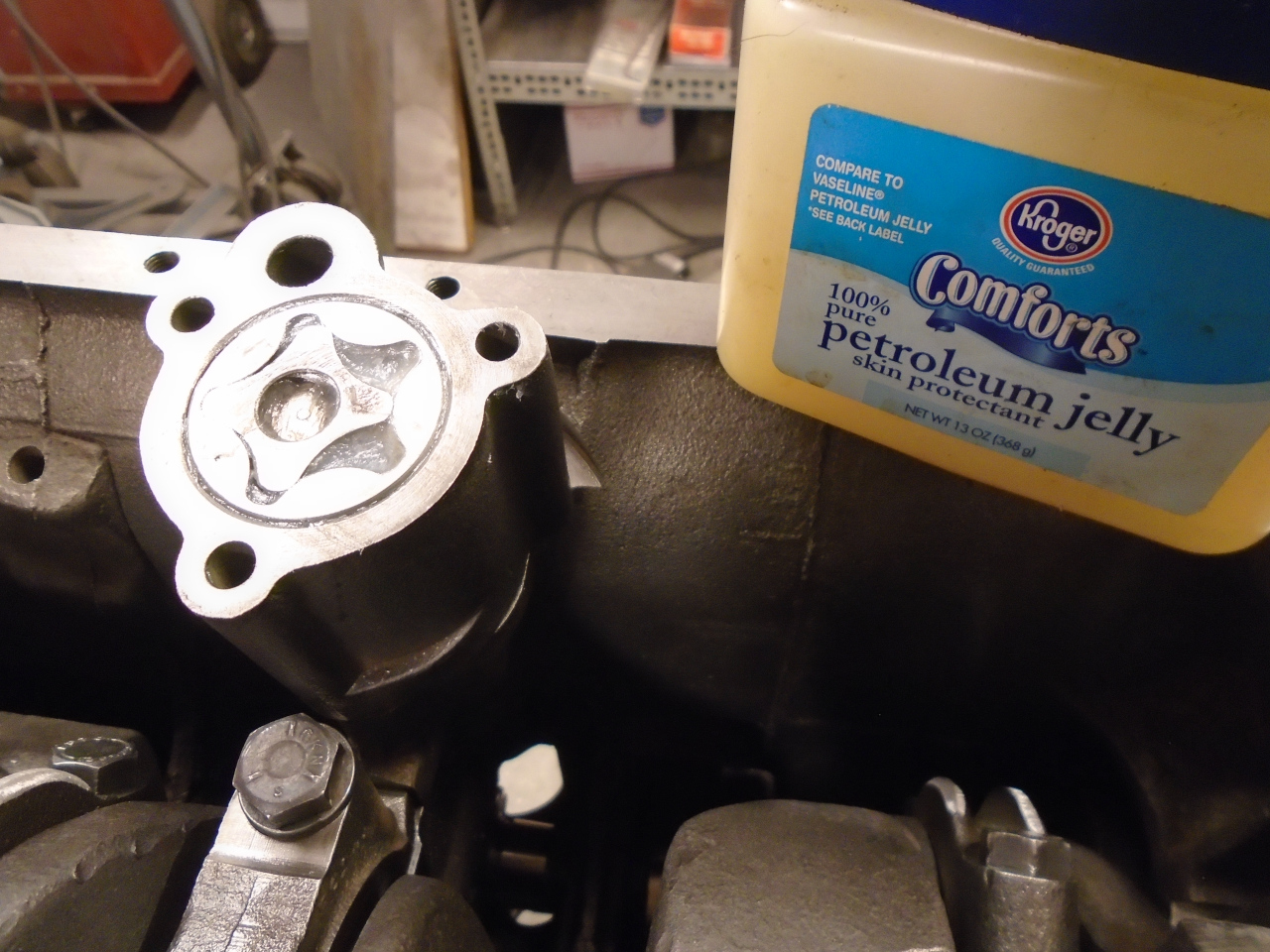
So the pump shaft was shoved down the hole in the bushing and
seated on its boss. To help with priming the pump, it's a
common practice to fill it with petroleum jelly or something
similar. Then the cap was set in place, and the unit bolted
down.
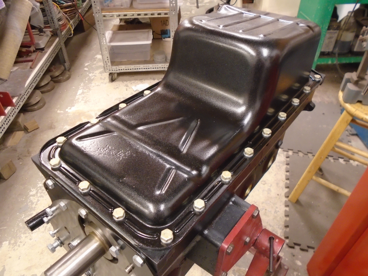
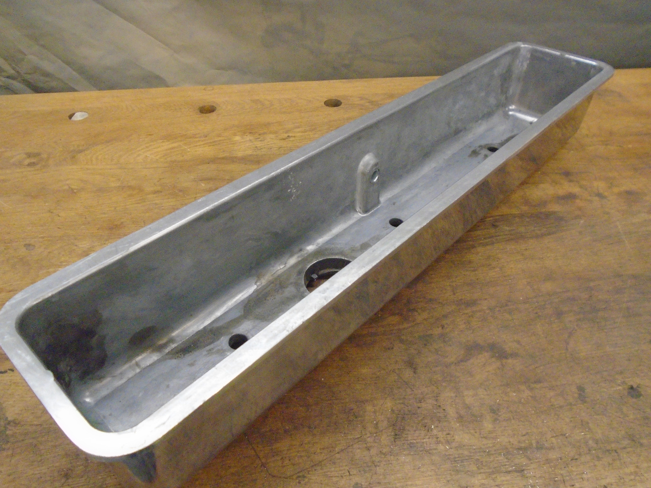
The oil pump was the last item needed before installing the
sump. My sump was of course totally gross. It was
caked with congealed oily grime on the outside, and had a layer of
tarry sludge on the inside. Somehow, it even managed to rust
in a few places on the outside. After a disagreeable time
cleaning it up and removing what paint was left, it didn't look
too bad. There were a few dents and some rust pitting, but I
thought it plenty good enough to use. After a little body
work, I shot it with a two part epoxy primer, and top coated with
a tough, textured paint often sold as truck bed liner. Also
cleaned up and replated the original fasteners.


A new gasket, liberally treated with Permatex 3D, and the sump
went home.
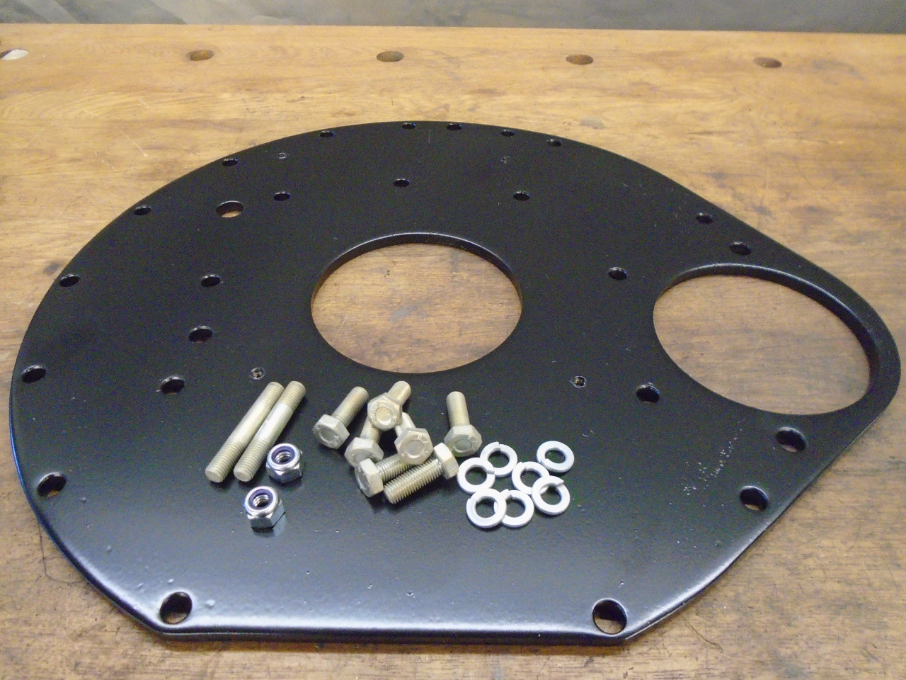
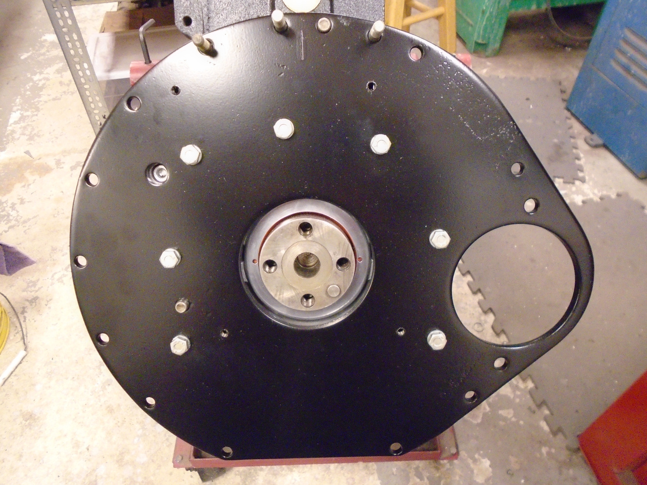
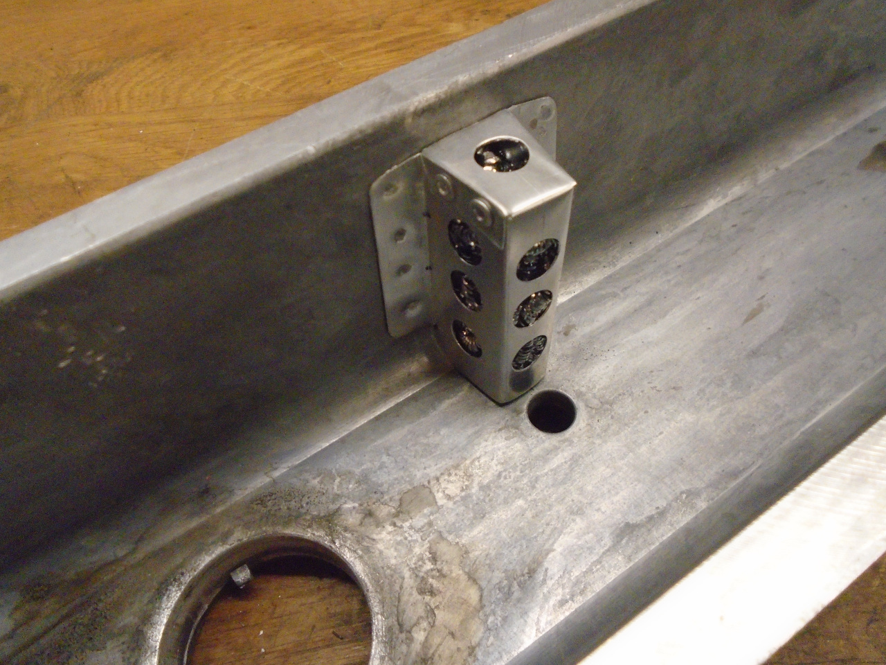
Next step was the rear engine plate. The plate has no
exposure to the inside of the engine, and no gasketry on it, so I
just painted the whole thing. It was actually powder coated,
and represents just about the largest thing that will possibly fit
in my oven. I do realize I will have to somehow ensure an
electrical return path for the starter.
So now it was just the topside of the engine that was still
open. In preparation for installing the head, I dug out the
head studs. One of them had its nut galled on, so I had to
order a stud and nut.
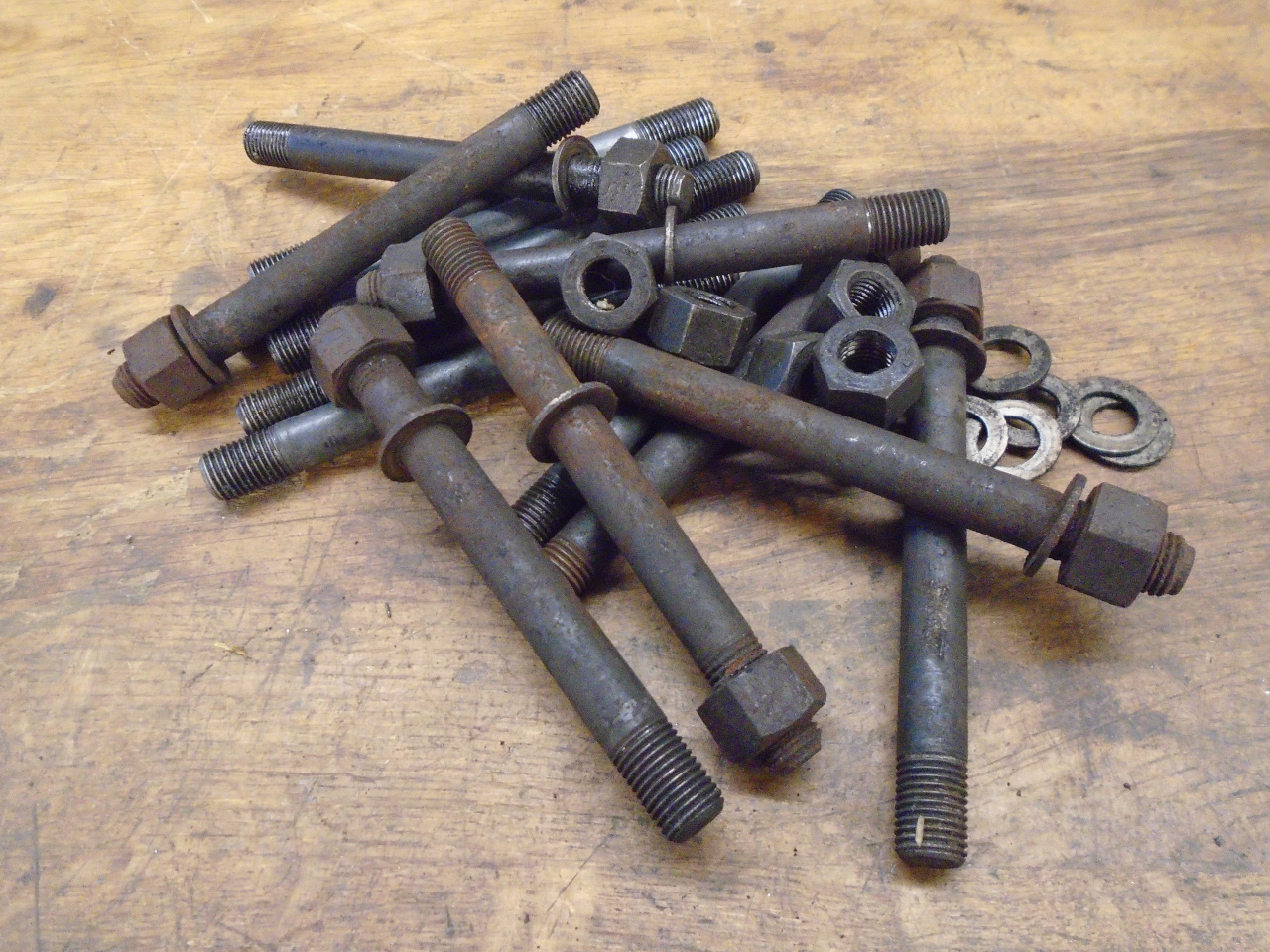
In thinking about the head fastenings, I remember my
disappointment when I raised the bonnet of my TR6 shortly after
finishing it. Everything in the engine compartment was still
pristine, except for some small but glaring areas of rust that
popped out at me. The rust was on the exposed head
nuts. Now I realize this is a small thing, but it was hard
for me to ignore. I guess I've come to peace with it on the
TR, at least for now, but I wanted to try to prevent it on the GT,
and now was the time. I selected the seven best studs and
nuts, and zinc plated the nuts and the top threads of the studs,
then chromated them for extra protection.
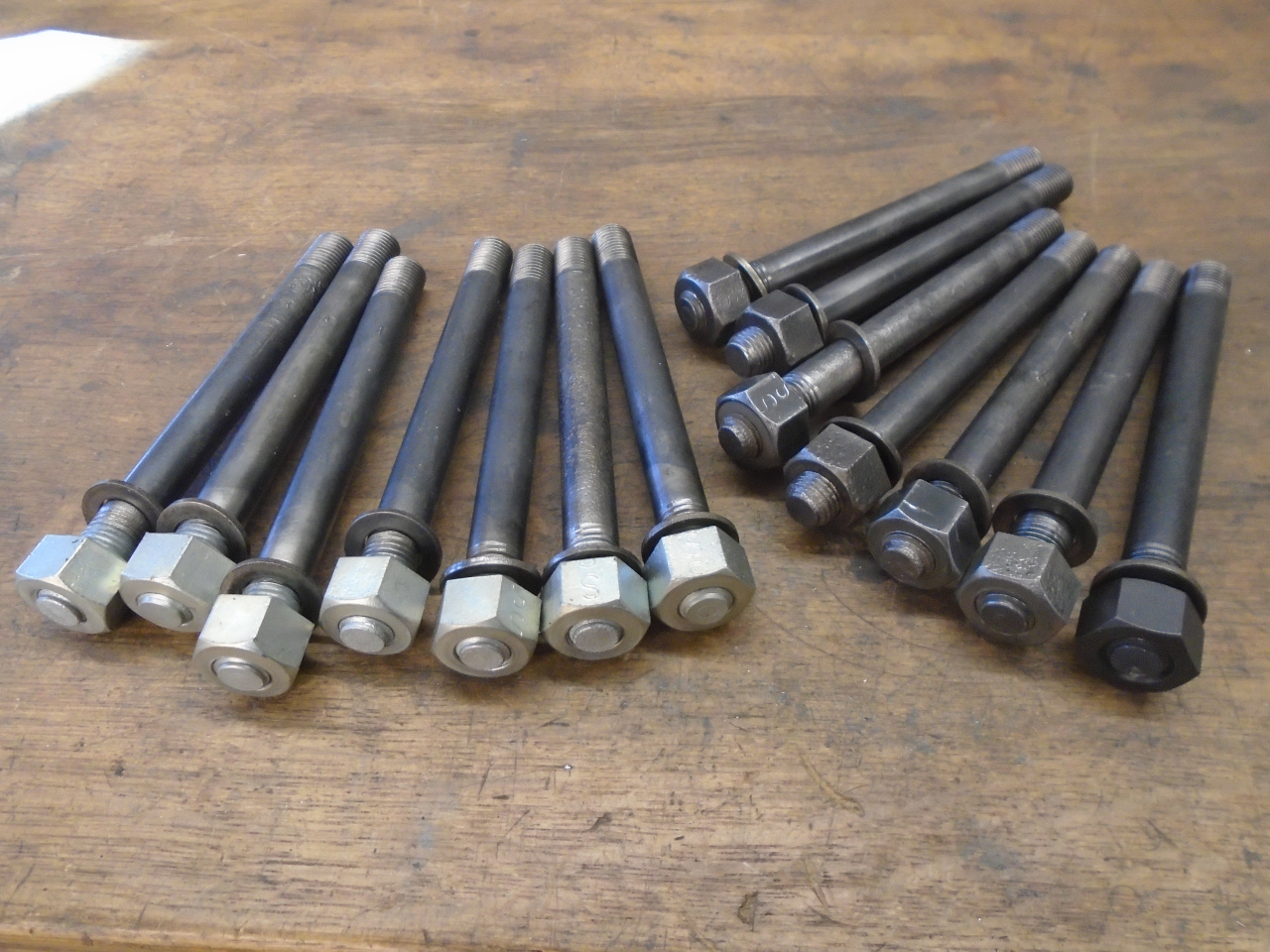
Then into the block they went. Then the new head gasket.
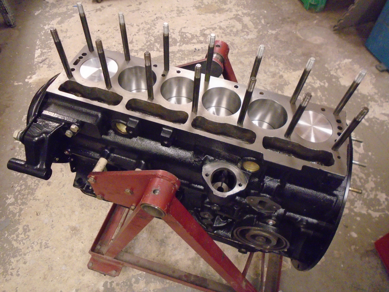

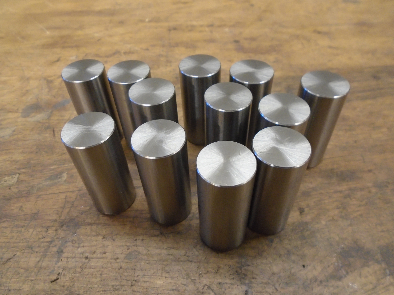
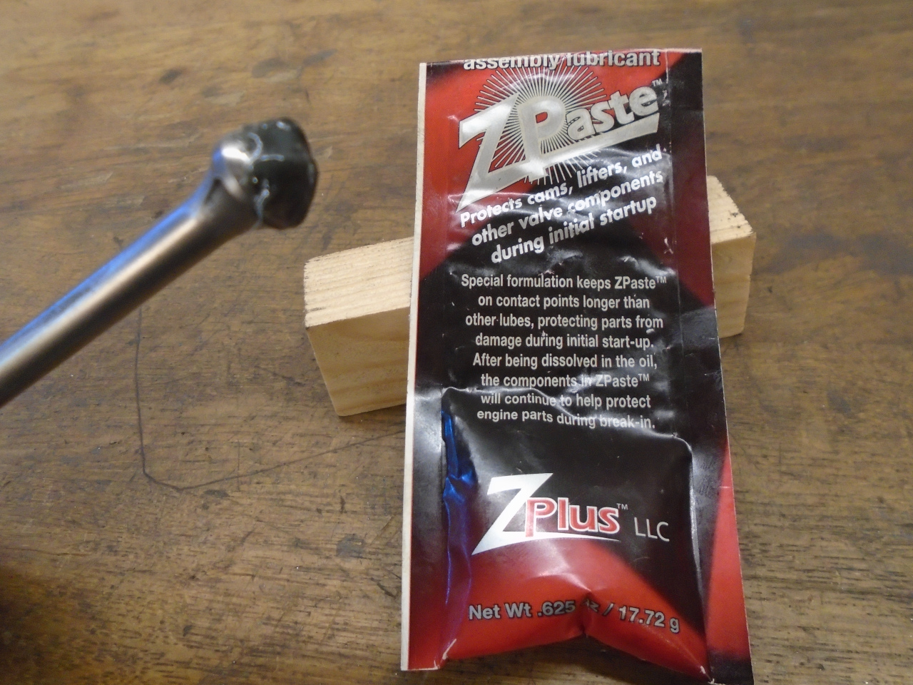
Dropped in new lifters after applying some special zinc loaded
assembly lube to their faces.
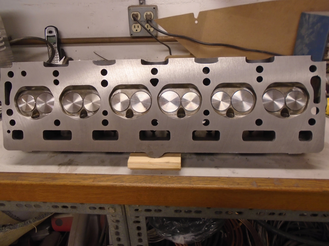
Retrieved the rebuilt cylinder head
from the bag it was stored in, dropped 'er on the block, and
torqued 'er down.

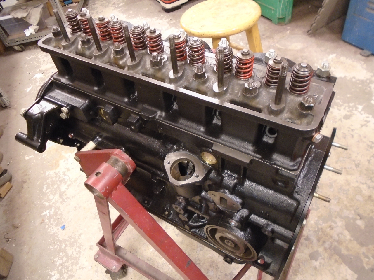
Lowered in the pushrods, again with some zinc assembly lube.
These are the original pushrods. I wish I'd thought to order
new ones, since wear might be a little accelerated in mating a
worn surface to a new one in the lifter.

Then popped on the assembled rocker gear
and set the rocker clearance. I was pretty sure that the
small amount I had shaved from the head and the block would not
affect fitment of standard length rods, and that was the case.

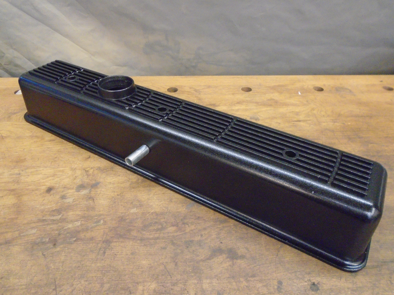
So now the last thing to do was decide on a rocker cover. I
did some quick mental calculations and determined that the budget
could support a little bling in that department, so I ordered
some.

I used the same cover on my TR6, and am pretty happy with
it. One main functional difference between this cover and
the stock one is that it lacks any kind of baffle for the vent
tube. The space inside the valve cover can be filled with
oil mist and airborne droplets, and whatever device lives
downstream of that vent will see that oil unless something is done
to try to minimize it. The stock cover has a baffle with a
mesh-like material inside to try to intercept the mist,
consolidate it, and return it to the engine. I tried to
duplicate that function on the TR, and I decided to do it for the
GT, too.
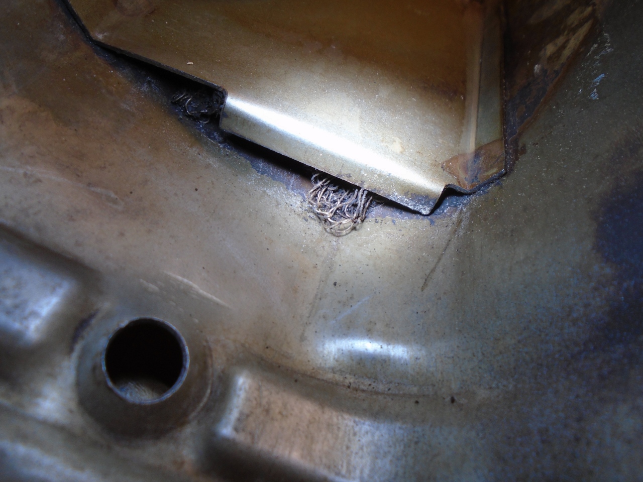
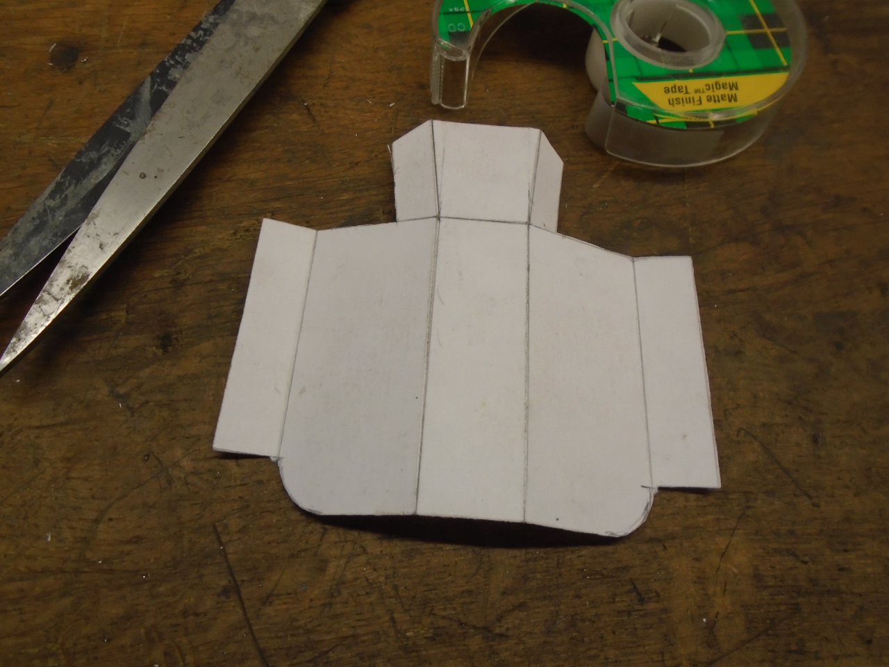
There really isn't much extra room inside the rocker cover to add
anything, and the placement of the vent tube really limits the
options. About the only choice is to put something between
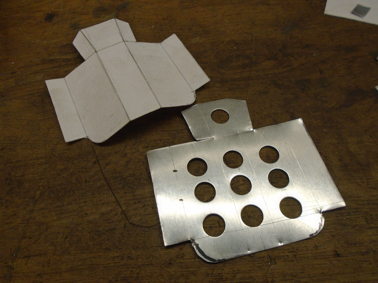
the #6 and #7 valve springs. I made a paper mockup.
The final design is a little shorter than this one.

Then a light sheet metal version.

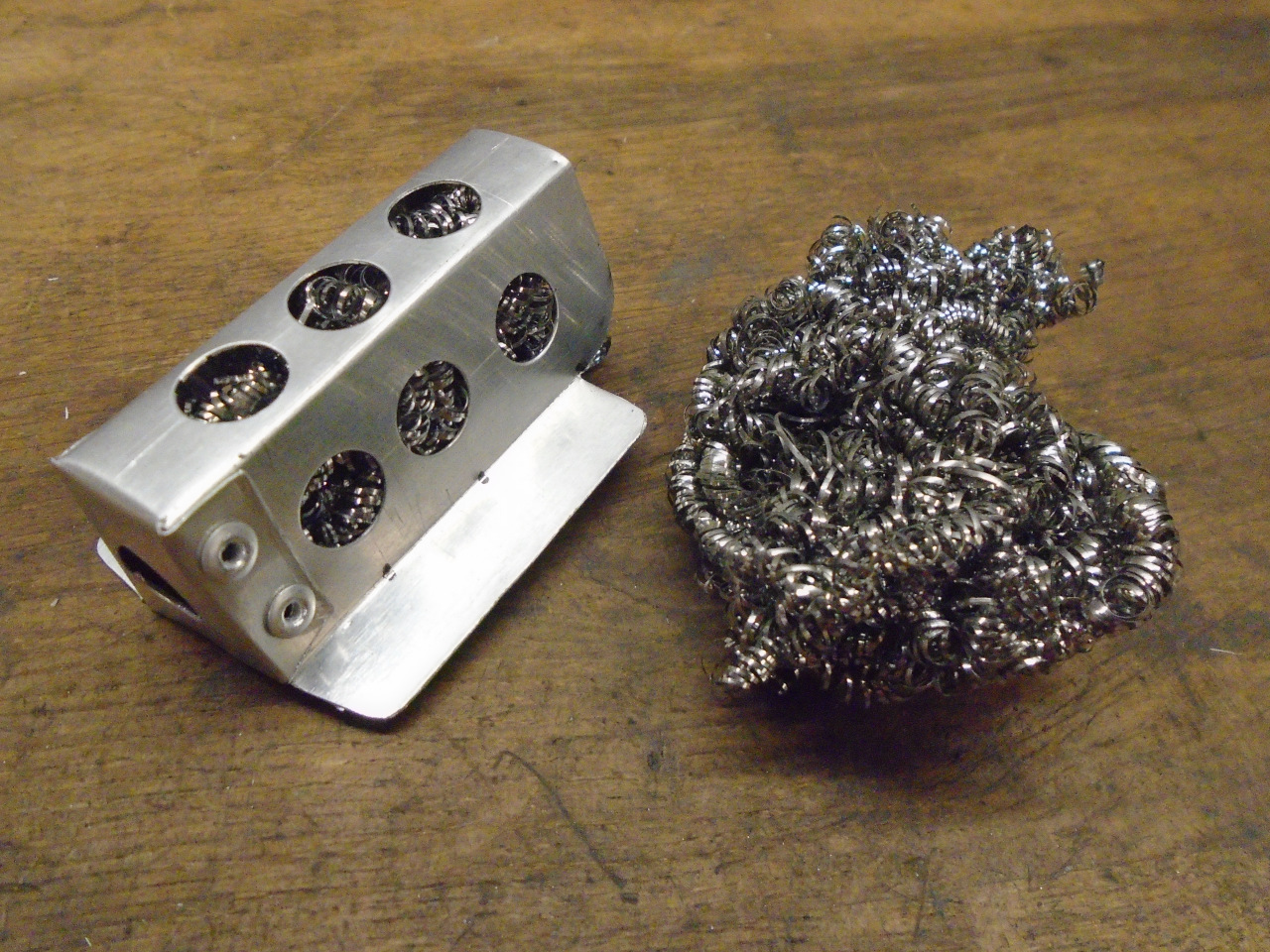
I used a stainless steel mesh to force a tortuous path to any
airborne oil. If it looks like a pot scrubber, there is a good
reason for that. I was pretty careful to make sure there
were no short pieces that could get through the holes.
With that done, I did a little personalization to the top of the
cover. If the spacing of the curved grooves looks pleasing,
it's because they mimic certain patterns in nature.

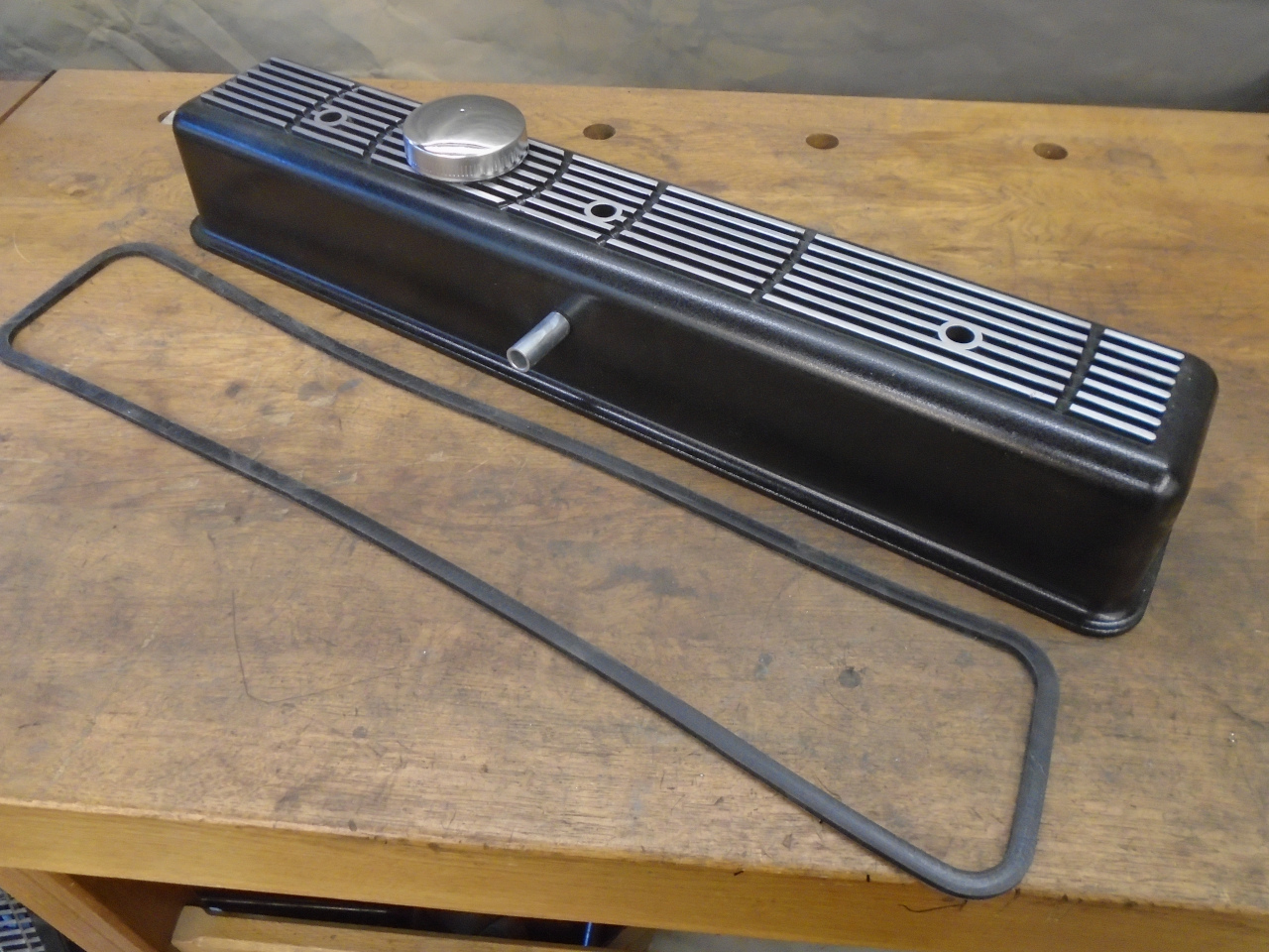
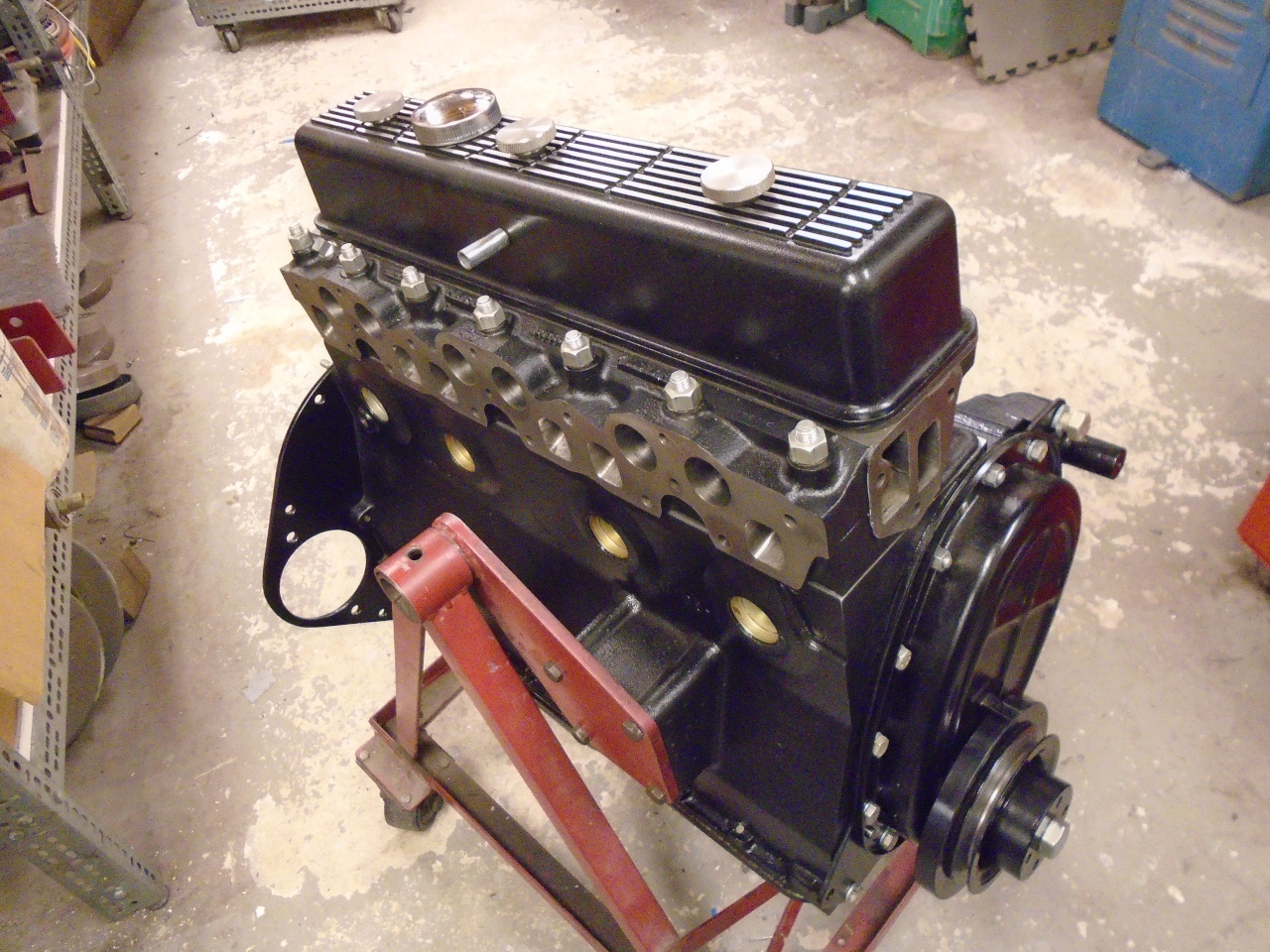
Primed and painted the cover with a textured black paint...
...then sanded back the ribs...
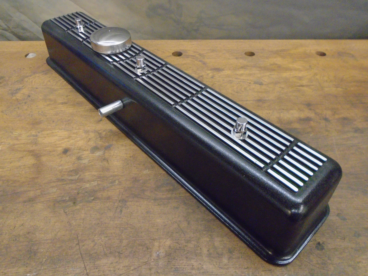
...and glued on the silicone gasket.
I really liked the look. Well, except for these
fasteners. They just looked, I don't know, too dainty or
something. Also, though they fit fine on the 5/16-24 studs
on the head, the hex on them is oddly 13 mm metric.

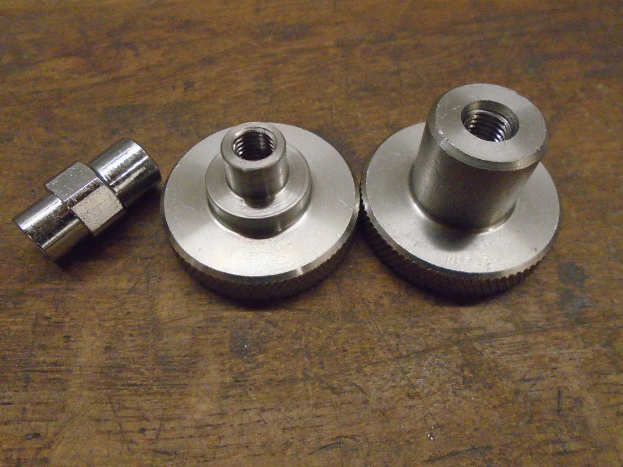
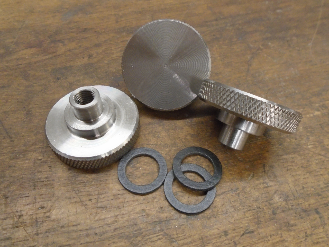
So I bought three of these stainless bad boys.
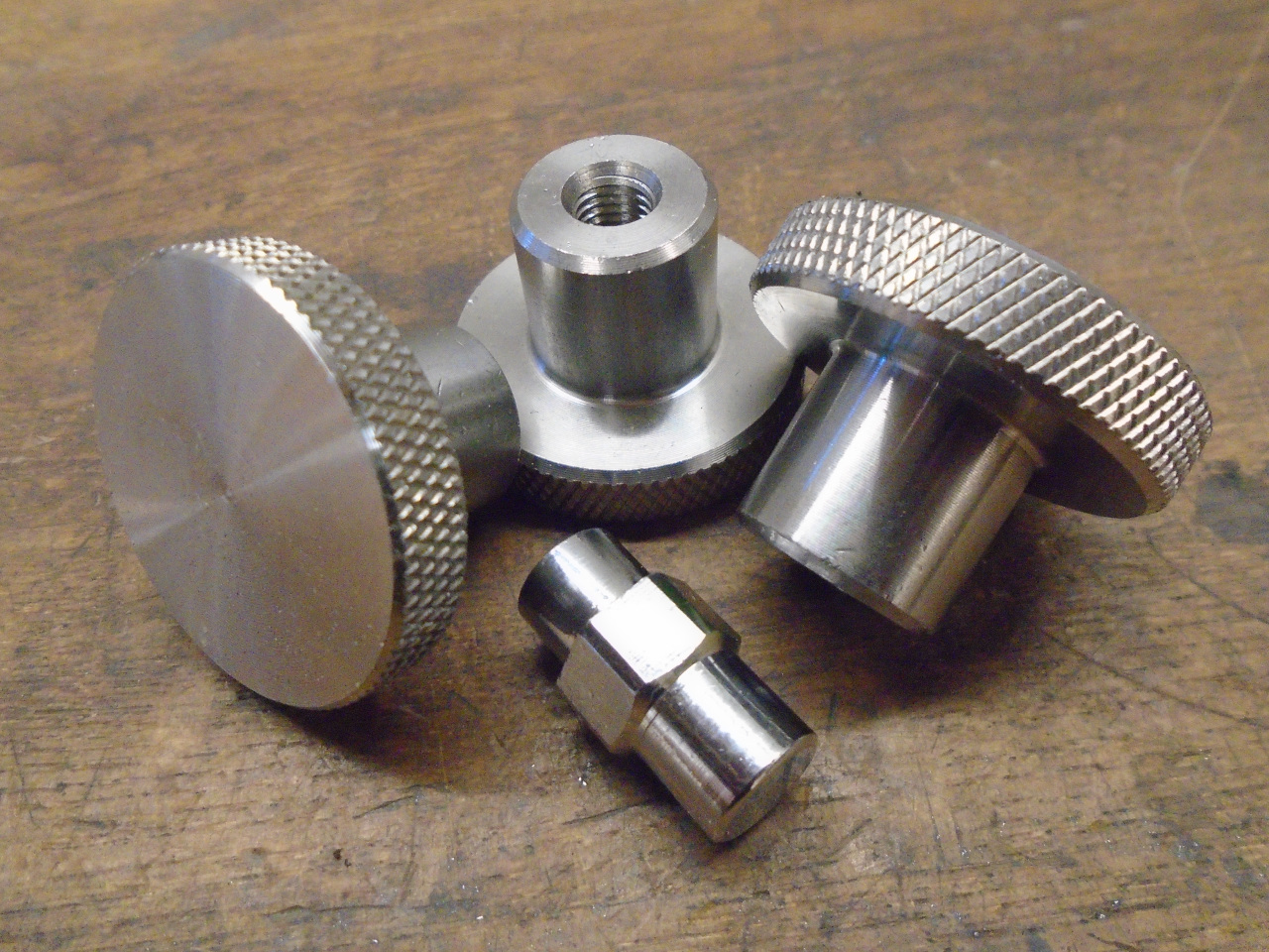
It took a little modification to make them fit. I actually
made them sit a little lower than the ones that came with the
cover, since I know the bonnet bulge is very close to the
cover. The little plastic washers help with sealing, and
prevent teh stainless from rubbing directly on the soft aluminum.
I like the fasteners better than the supplied ones, but I'm not
sure I love them. Time will tell.
The engine will now sit in a corner of the shop until I need
it. Probably not until next summer at the soonest. The
piece of hardboard is my OCD version of stuffing rags in the ports
to keep crud and critters out.

This is a big step, and a fairly expensive one. I think I
have nearly $1000 in the engine, mainly for the pistons and
cam.
I can't wait until I can lower the engine onto the frame. In
the meantime, I'll be working on a way to get it up a flight of
stairs to the garage.
Comments to Ed at elhollin1@yahoo.com
To my other GT6
pages