To my other GT6
pages.
April 13, 2020
Rocker Gear
The stock GT6 engine was very conventional overhead valve (OHV)
engine. The valves were operated from a camshaft in the
block through cam followers and pushrods. At the top of
the engine, the motion of the pushrods was transferred to the
valve stems by individual rocker arms. The arms are
basically just levers. They are designed with a mechanical
advantage of around 1.5:1, with the greater travel on the valve
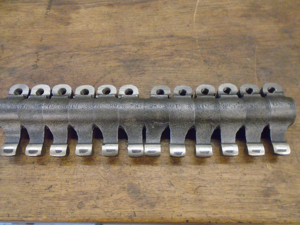
side. All 12 rocker arms ride on a single shaft with
appropriate springs and spacers for location.
The rocker assembly, including rockers, shaft, and mounting
pedestals, can be removed from the head as a unit.
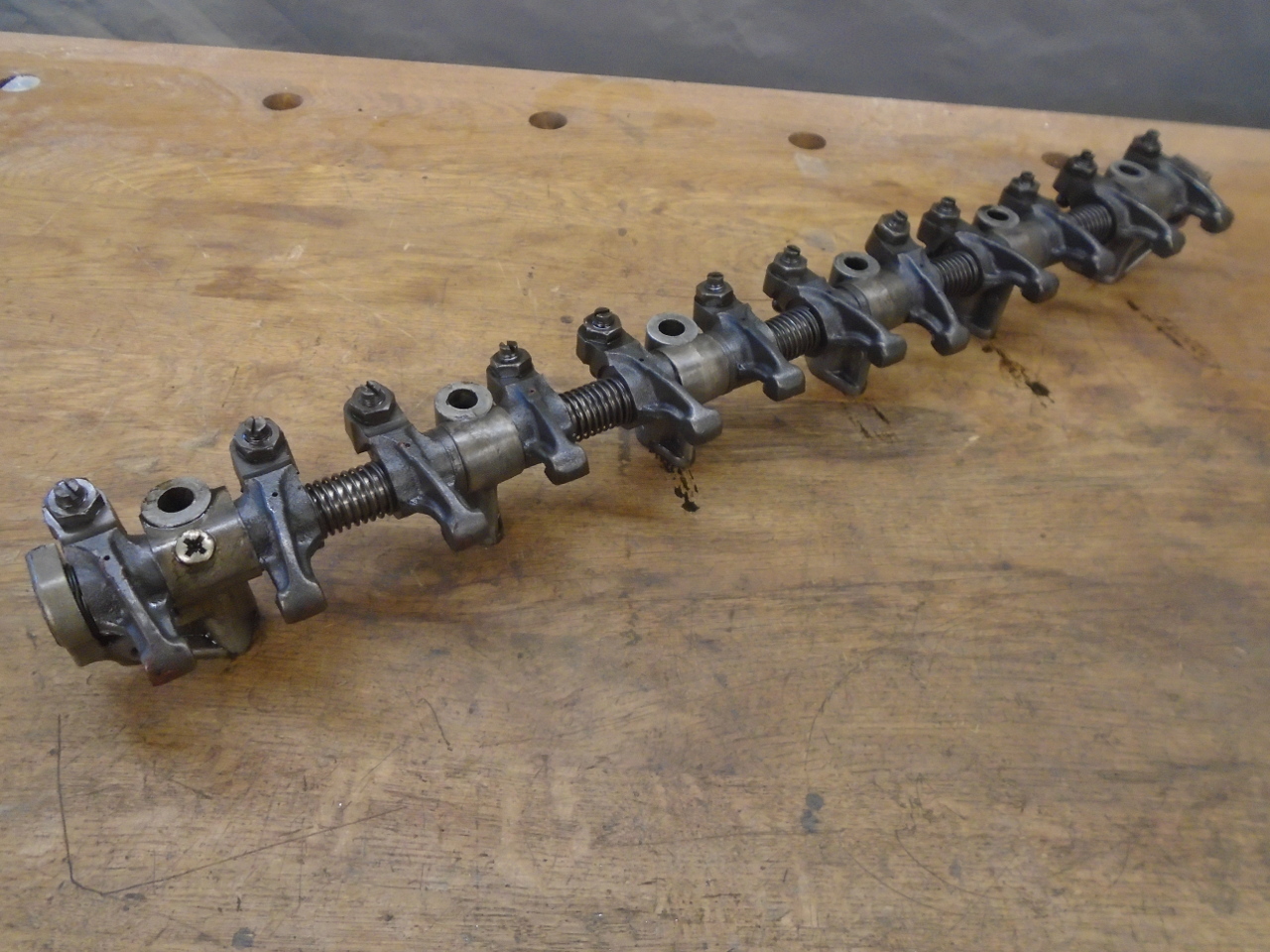
Everything slides off the shaft.
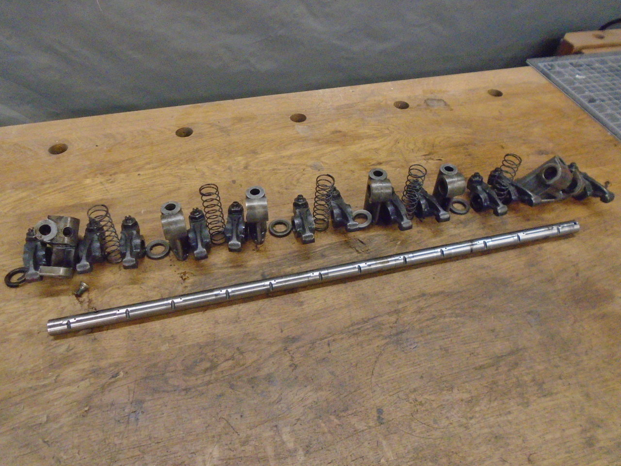
My rocker shaft had significant wear where the rockers
rode.
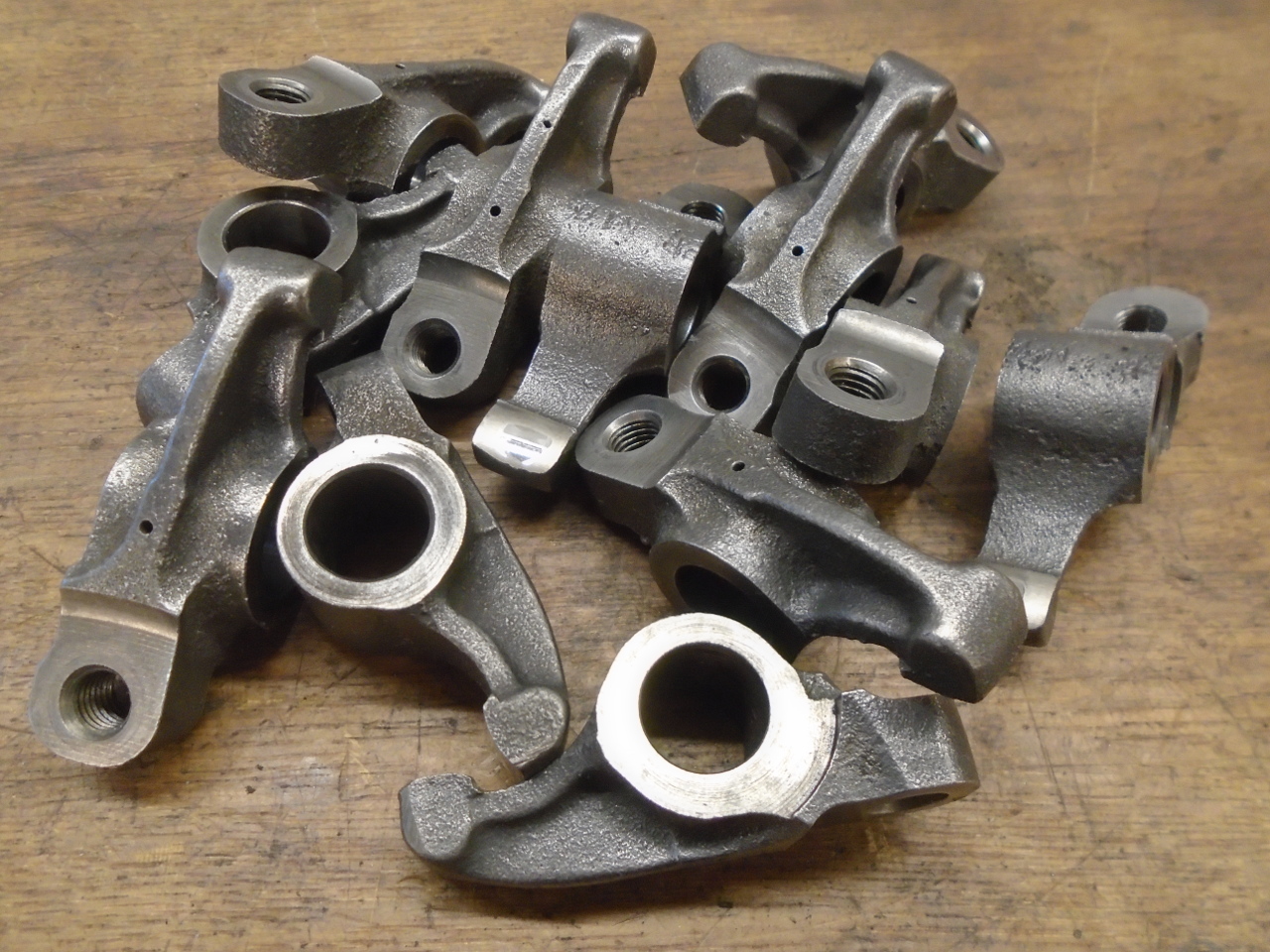
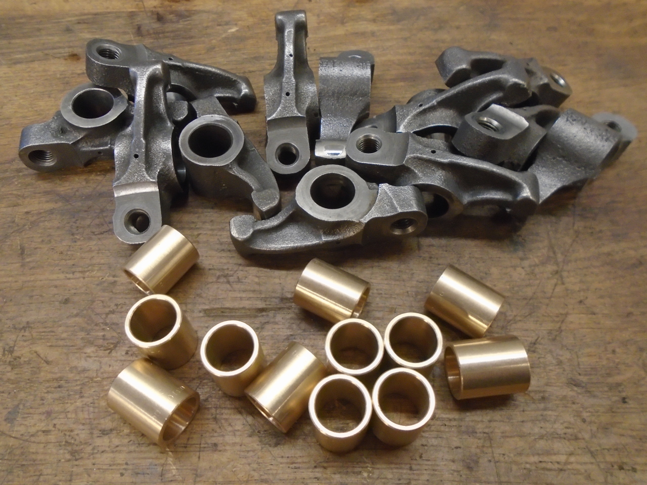
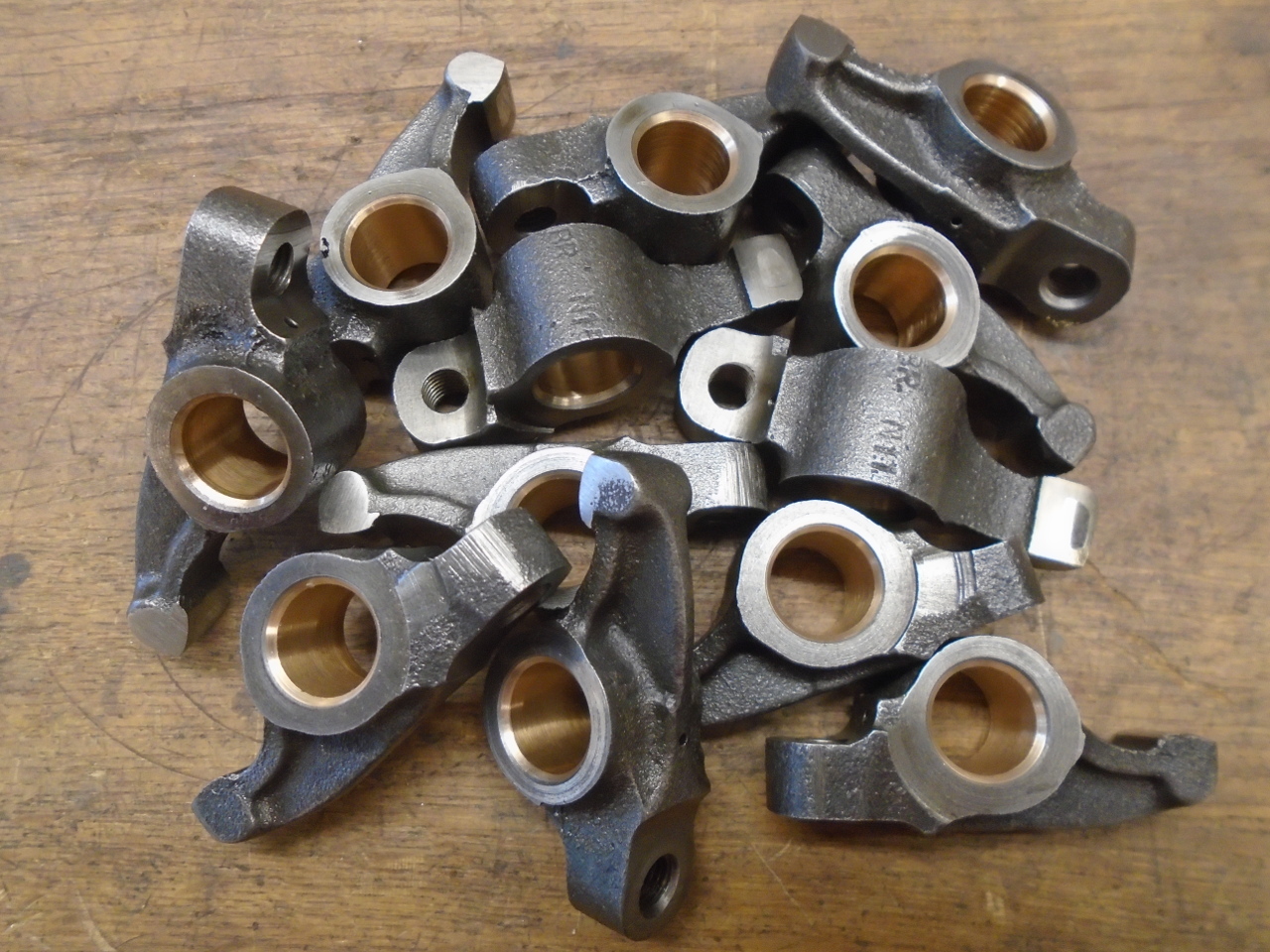
The rockers themselves showed some wear in the bores, but were
otherwise in decent shape.
When an Engineer designs a mechanism like this, one of the
things she has to bear in mind is wear. A good design has
the component most subject to wear also be the easiest or
cheapest to replace. In the case of this rocker assembly,
the shaft is cheaper than all of the rockers, so the shaft
typically wore faster than the rockers. I'm not totally
sure this was intentional, but it is at least fortuitous.
However, in this case, I had decided to move to a higher grade
rocker shaft with better wear performance. This could tip
the balance to more wear on the rockers. My answer to this
was to sleeve the rockers with replaceable bronze bushes.
Bushed rockers are commercially available for this engine, but
there was really nothing much wrong with my rockers.
For strength reasons, I didn't want to bore out the rockers any
larger than absolutely necessary, so I decided to use thin wall
(0.031") bushings. I couldn't find any of the right size
available, so I bought thicker (0.062") bushes. I would
probably have to ream the ID of the bushes anyway, so this
wasn't a big deal.
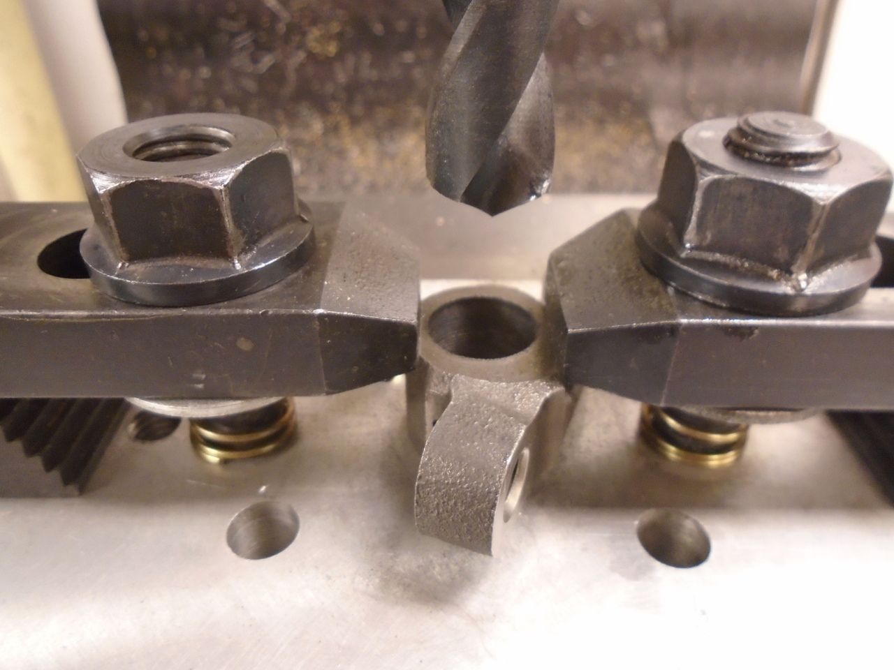
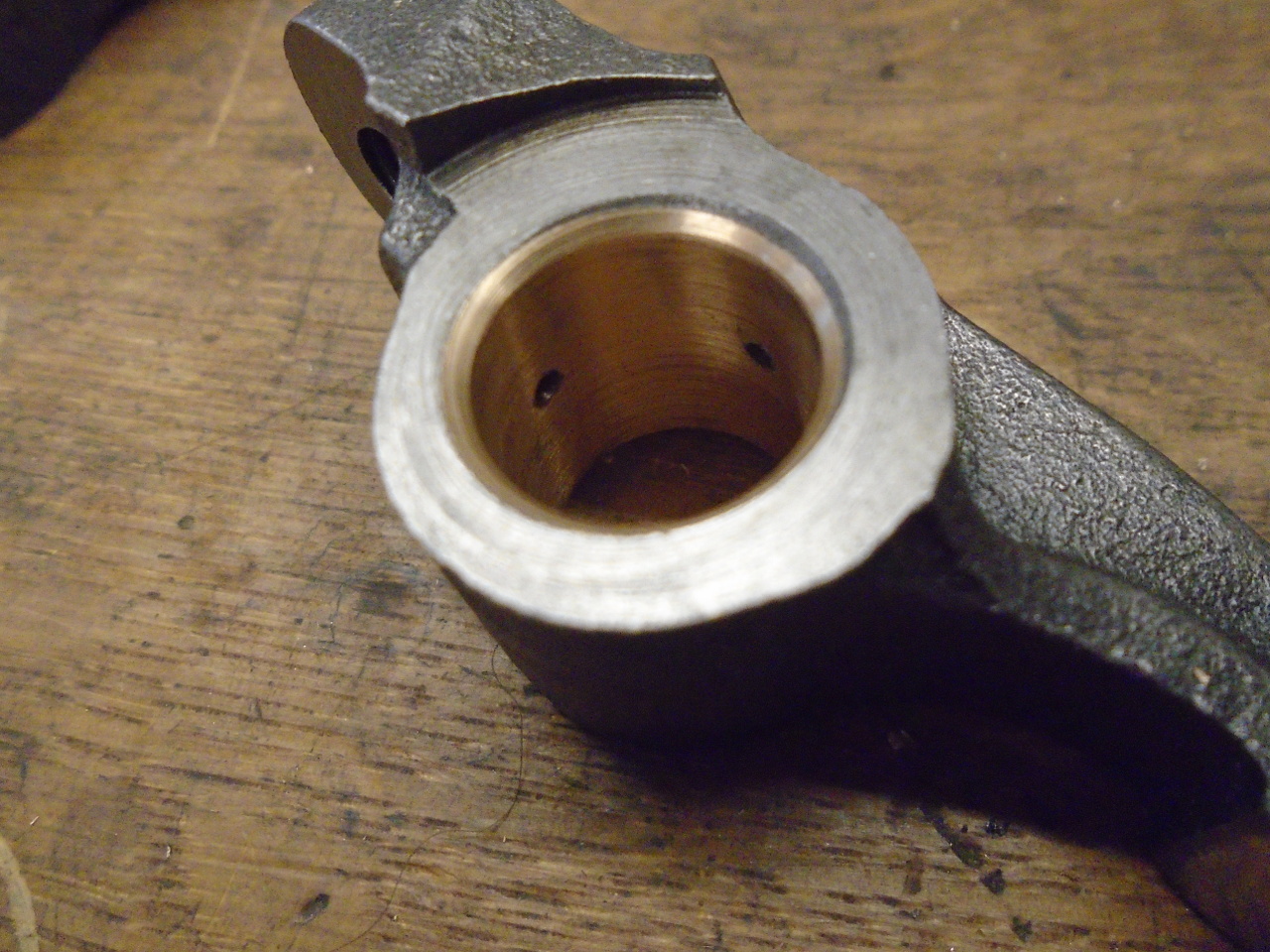
It was a multi-step process to bush the rockers. I did
this on a small milling machine, but I think a decent drill
press would work as well.
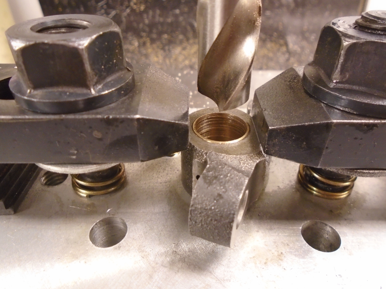
I cobbled a fixture to hold the rockers solidly. After
centering the rocker's bore with the machine axis, I drilled the
bore undersized for the bush OD, then reamed the bore for a
press fit of the bushing.
Then pressed in the bush, drilled it a little undersized, and
reamed to final ID.
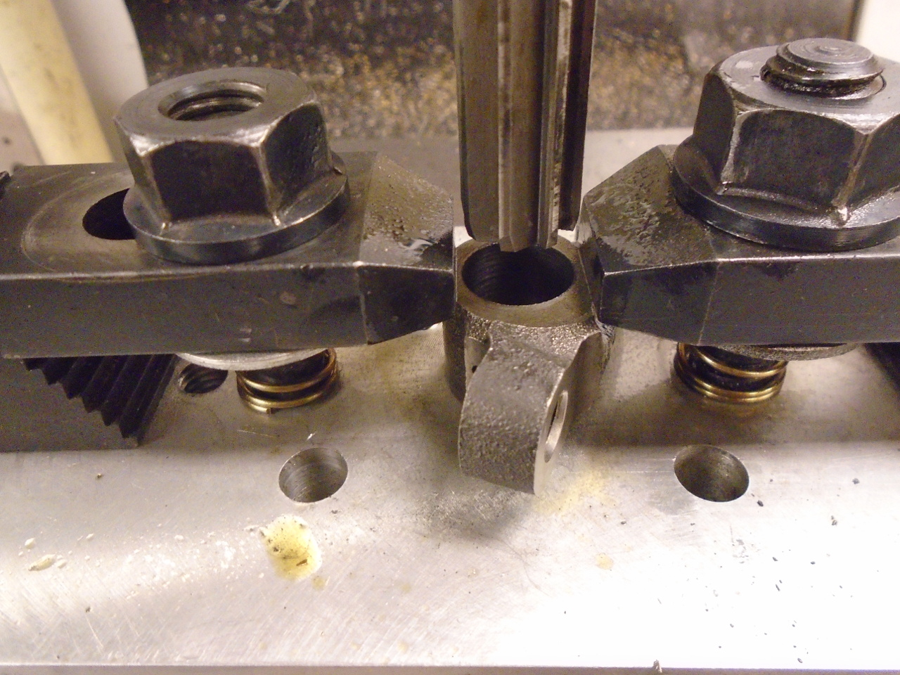
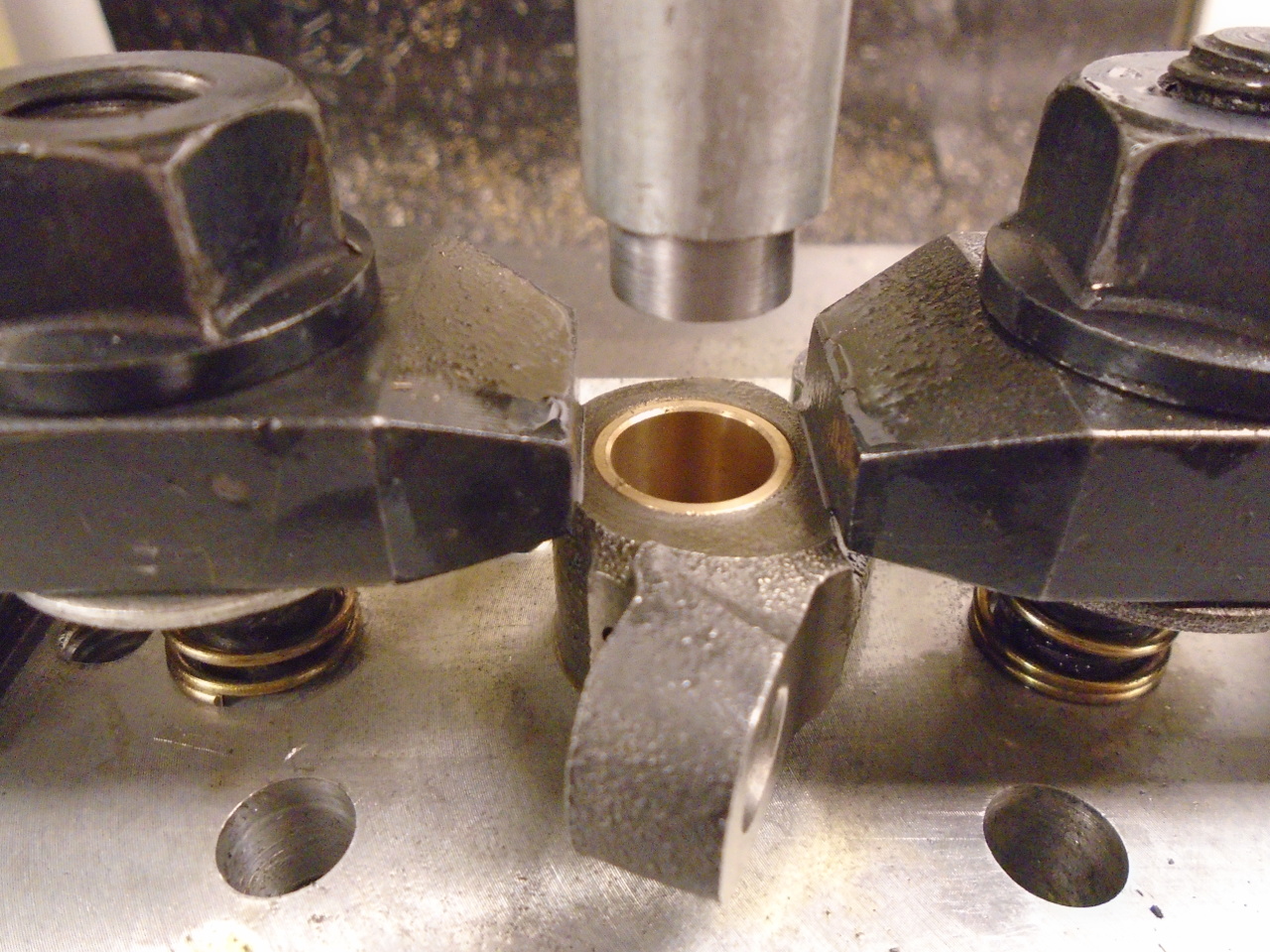
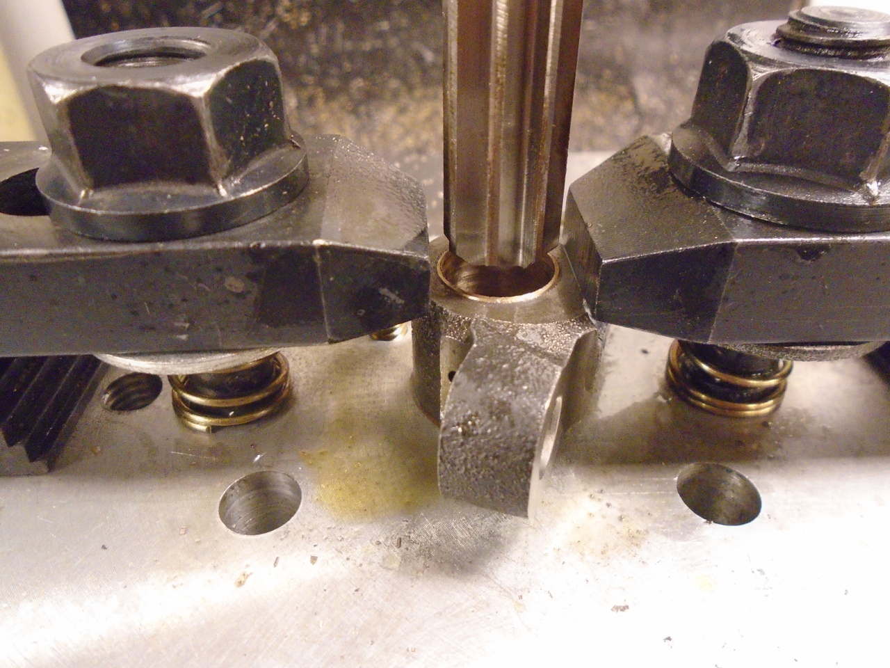
All of this was done to each rocker without removing it from the
fixture. This assured that everything stayed concentric.
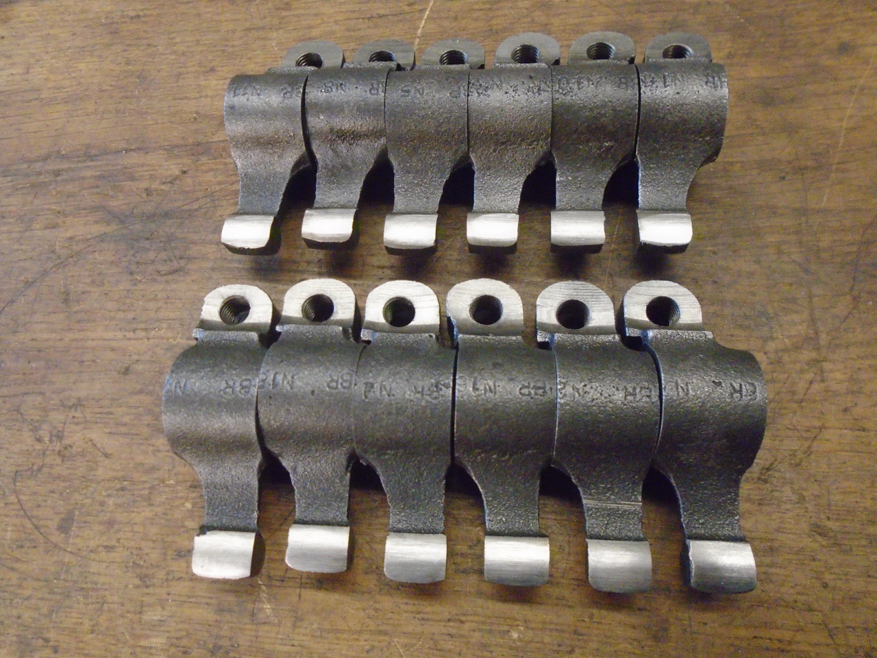
Then, in a following step, I chamfered both sides of each part.
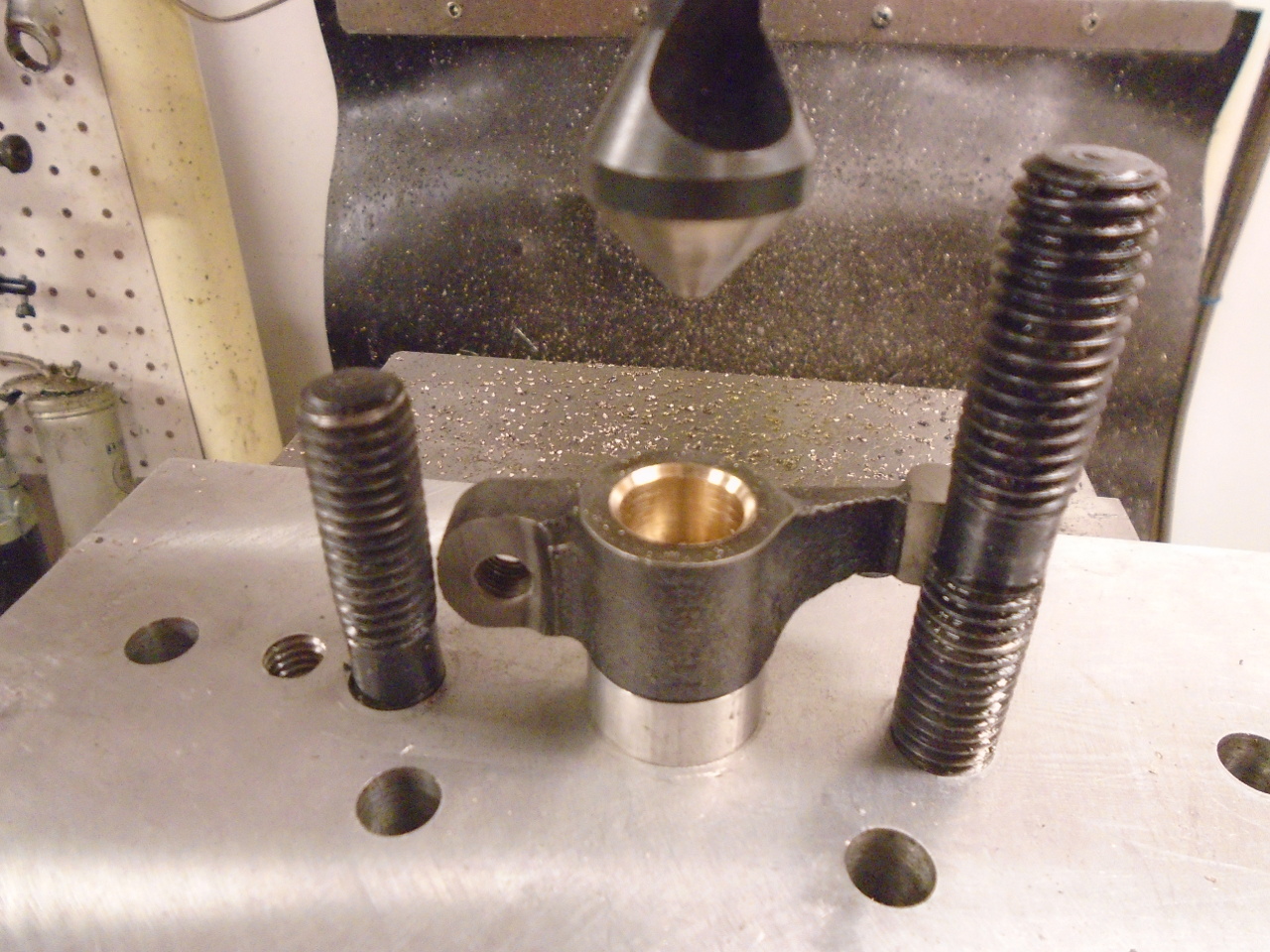
Once I go rolling, each part only took a few minutes.
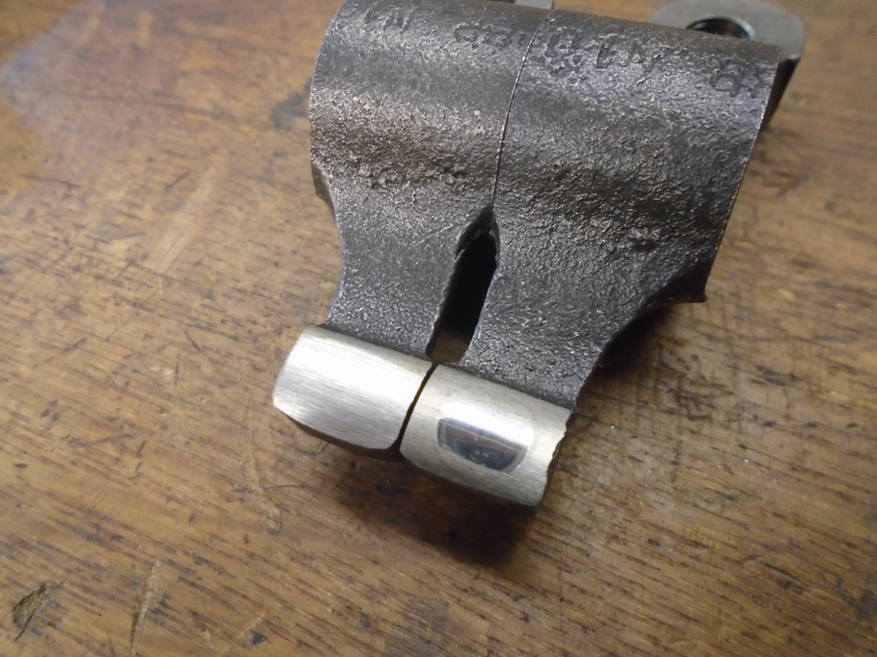
The only other sign of wear on the rockers was some minor
recesses on the shoes that bear on the valve stems. These
don't really affect function very much, but it can make it
harder to get an accurate valve lash reading.
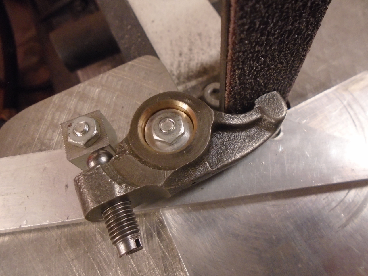
I made this little fixture that would rotate each rocker around
the center of its shoe radius.
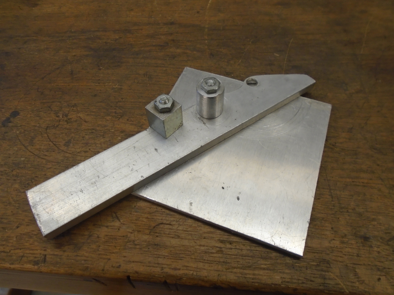
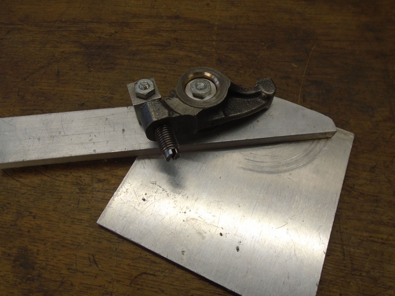
I clamp the fixture to the table of my little on-inch belt
sander. The rocker's lash adjuster screw serves as a fine
depth adjustment for the grinding.
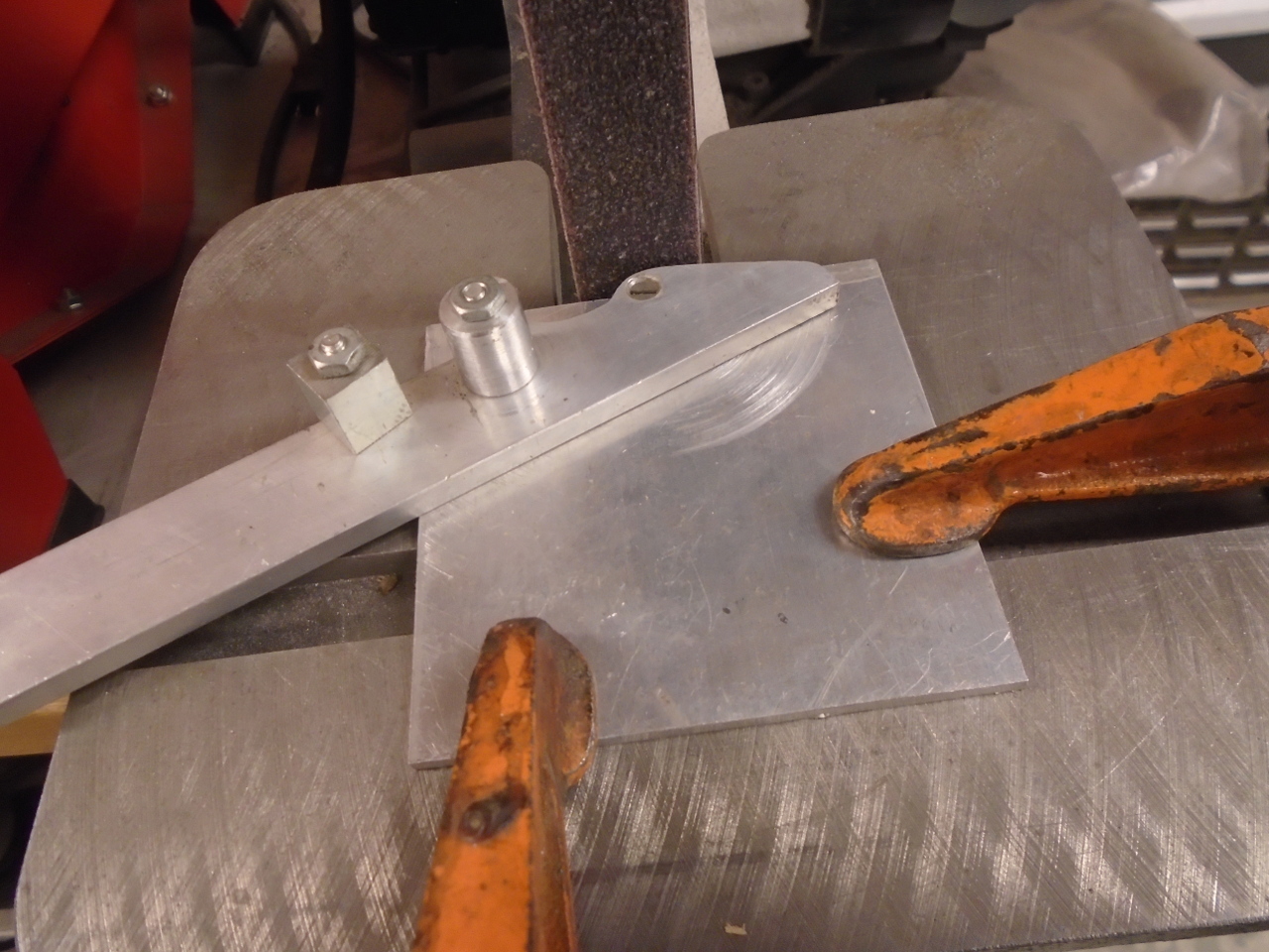
None of the wear spots were very deep. I think I only took
off 8-10 thousandths or so. I was mildly concerned that I
might disturb some case hardening, but a simple file test
suggested that the new surface was roughly the same hardness as
the old.
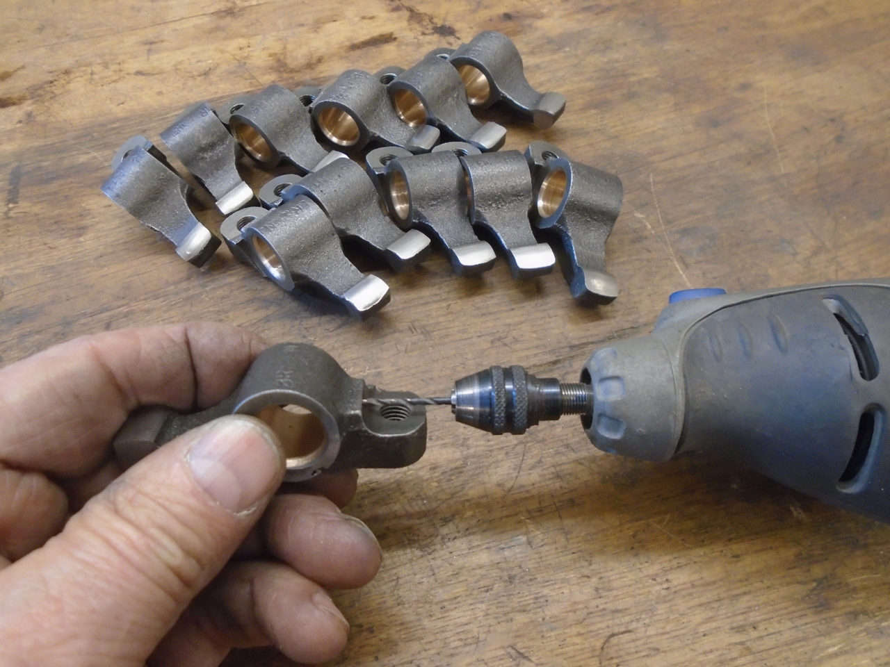
The last task was to drill the two oil holes in each
rocker. They are different sizes.
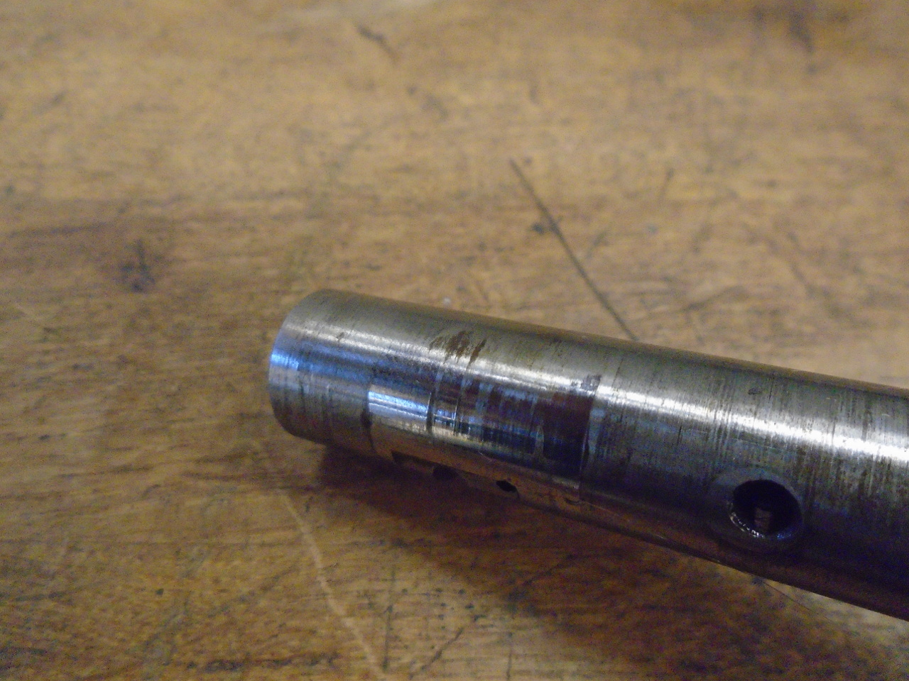
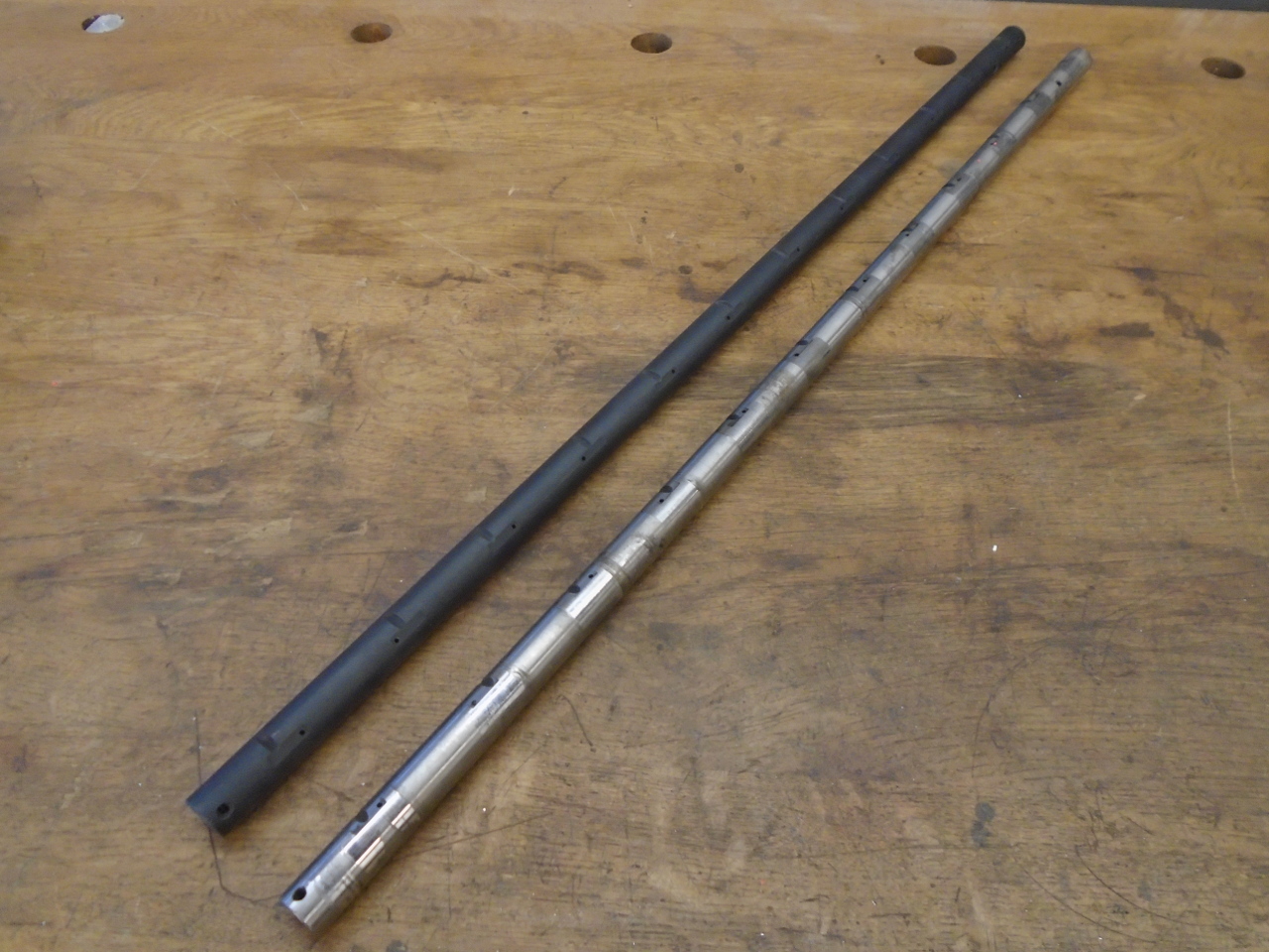
Then it was time for re-assembly. On the left is the new
rocker shaft. It is black because it has had a nitride
heat treating process that case hardens the steel.
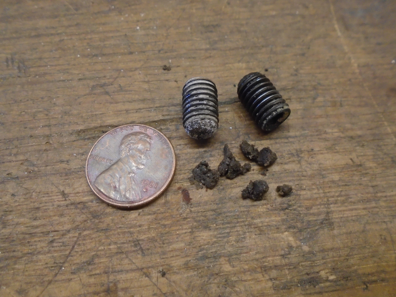
Because of quite a few past experiences, I always inspect new
parts pretty closely. I removed the set screw from each
end of the new shaft, and took a look down the bore. I was
sad , but not overly surprised to see that the hole seemed to be
plugged with something. I pulled out some fine gritty
substance that was packed against one of the screws. I'd
take a guess that it was something left from the grinding
process. The picture shows most of it. I had to swab
out the bore maybe a dozen tomes before the swabs came out
clean. And this was an "uprated" shaft.
I thought the easiest way to build the shaft was to just mount
the pedestals on the head.
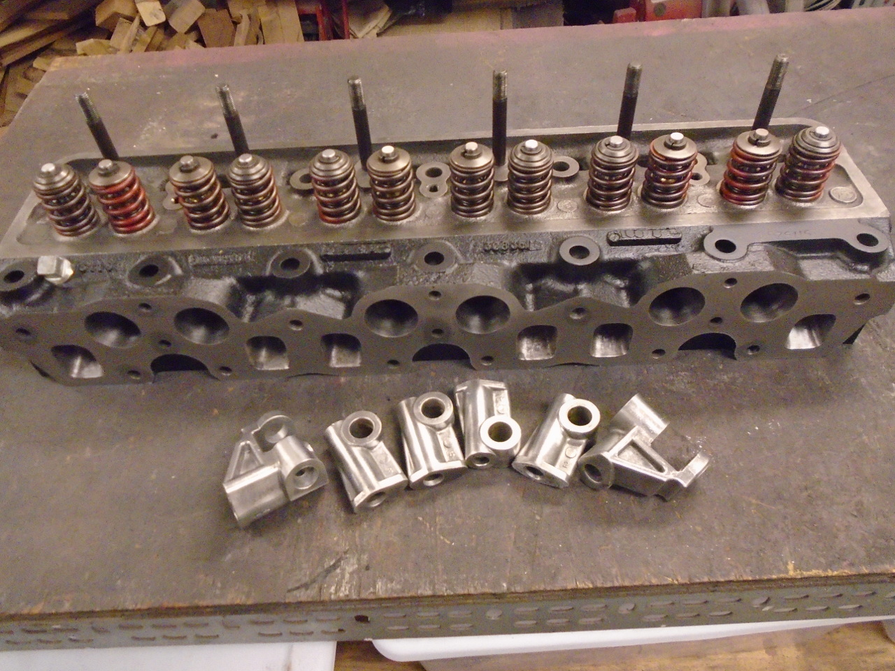
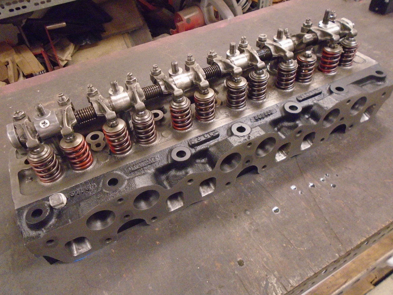
So, this pretty much completes the cylinder head. I think
I'll bag it up since the assembly lube is like a sticky dust
magnet, and it will probably be a year before I need it.
I'm glad this part is done. It seems sort of like a
milestone. The cost was just for the new shaft and the
bushes. Around $80.
Comments to Ed at elhollin1@yahoo.com
To my other GT6 pages.