To my other GT6
pages
March 21, 2020
Cylinder Head
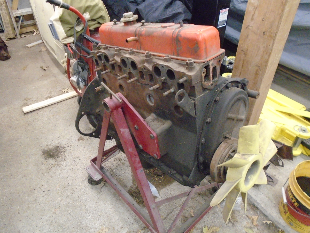
The straight six engine in the GT6 is certainly
outdated by modern standards, and was a pretty mature design
even in its own day. It's a very conventional overhead
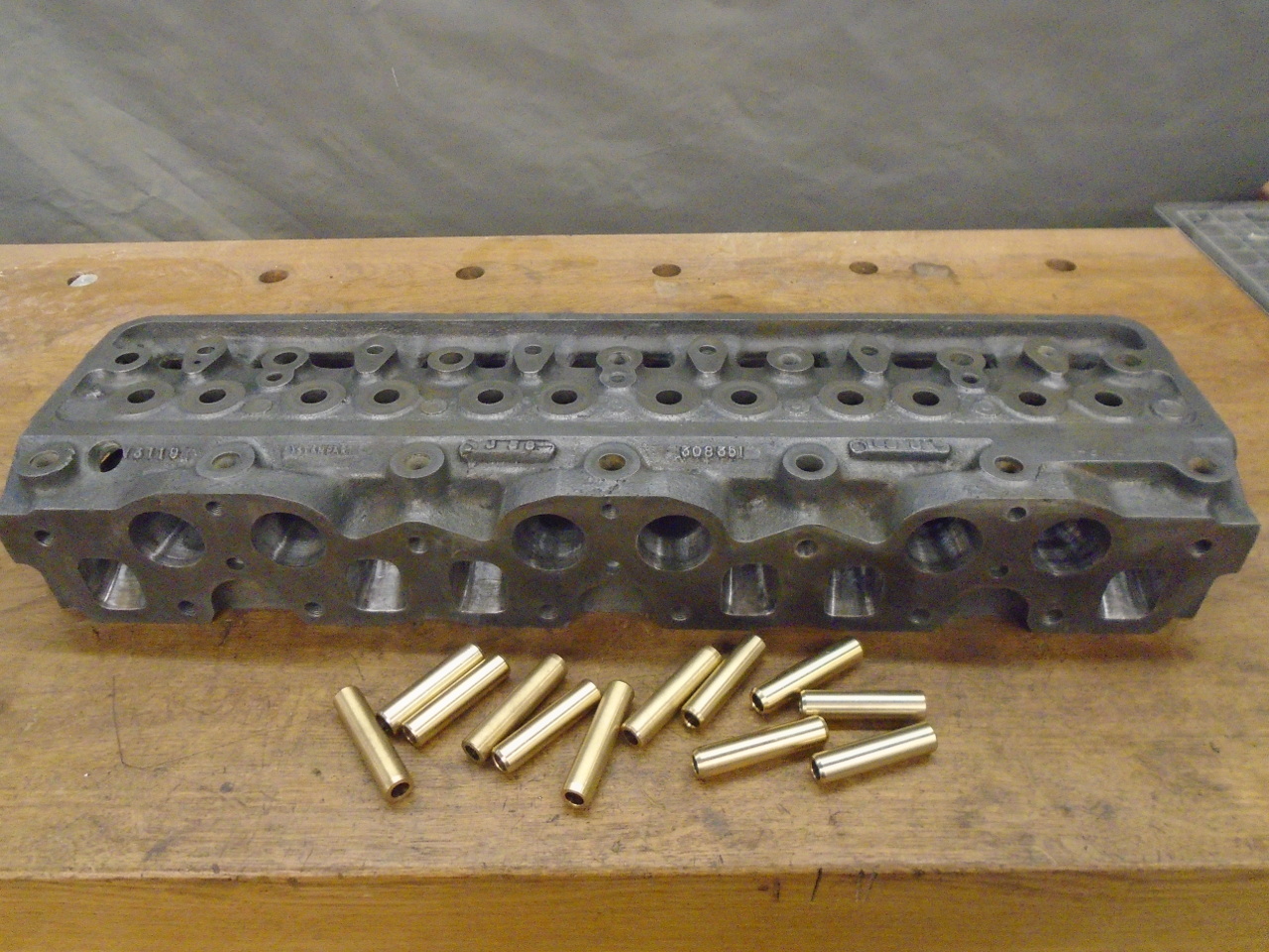
valve pushrod engine. The cylinder head is a beefy
60-pound lump of cast iron that holds the combustion chambers
and their two vertical valves each.
The first task on the cylinder head was to detach it from the
engine. I understand that this can sometimes be difficult,
but in this case, the head came along peacefully.
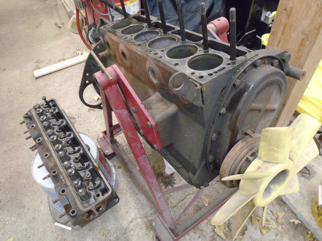
I cleaned off a bench for disassembly and inspection.
There weren't any big surprises.
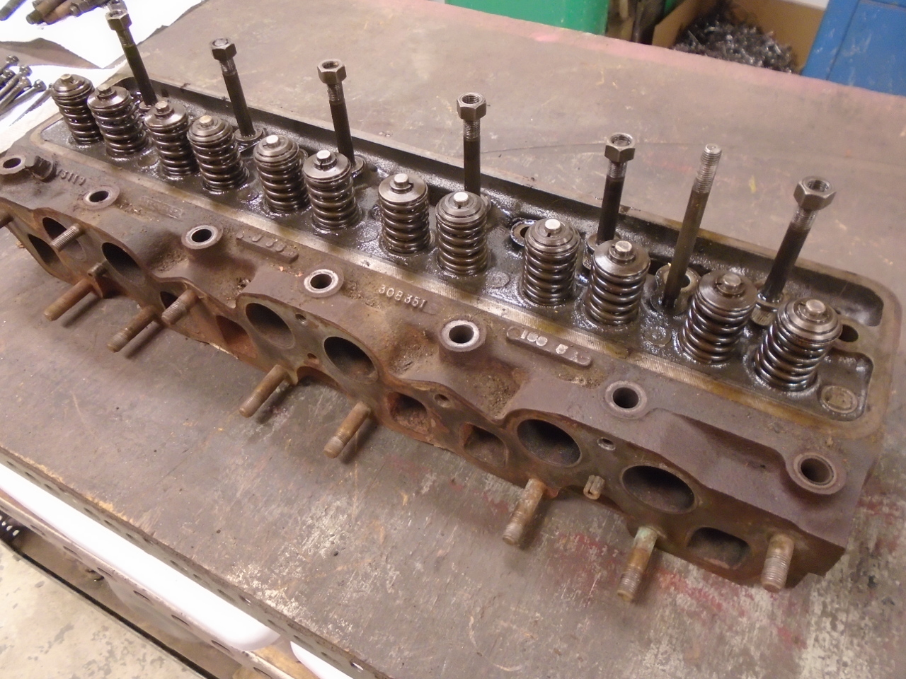
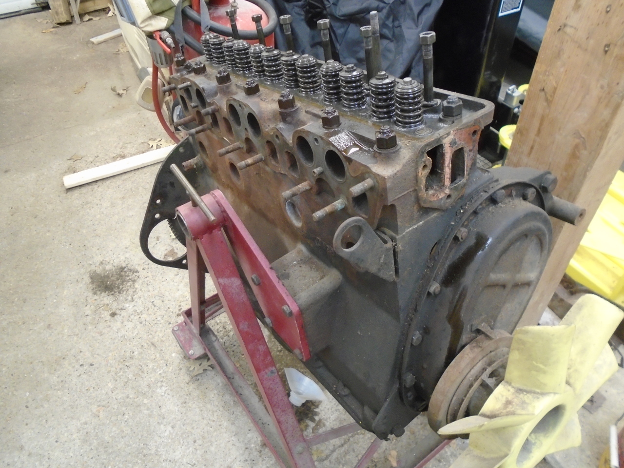
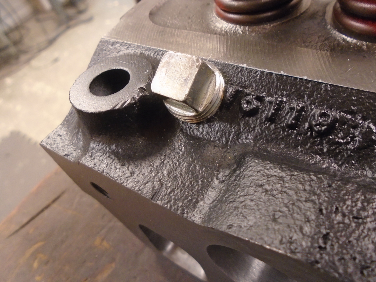
Disassembly was fairly routine. The water jacket plug at
the rear showed a little defiance. I had to drill it out.
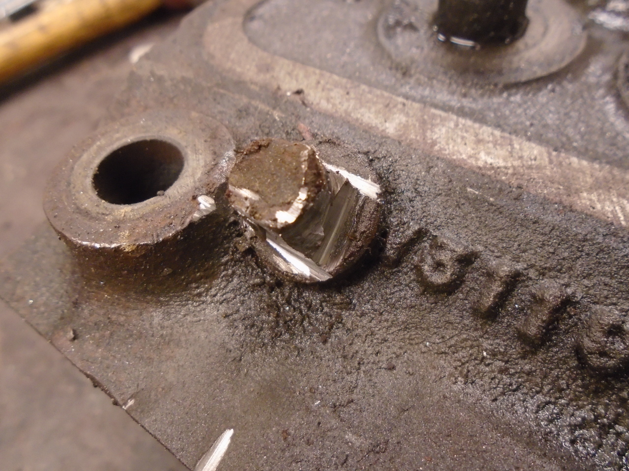
Also, the core plugs didn't respond to polite requests.
The remaining studs and valve gear came away without too much
undue violence.
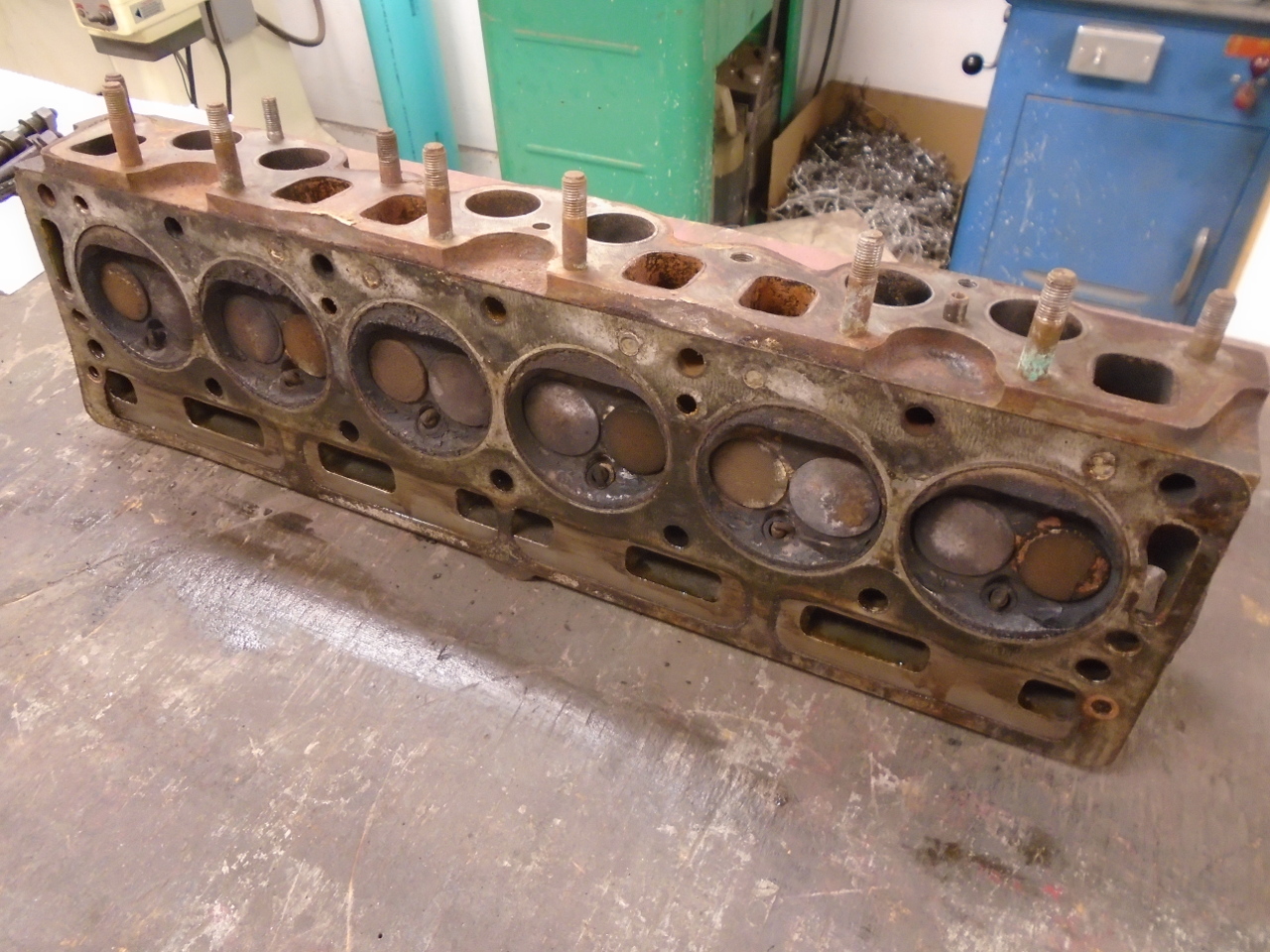
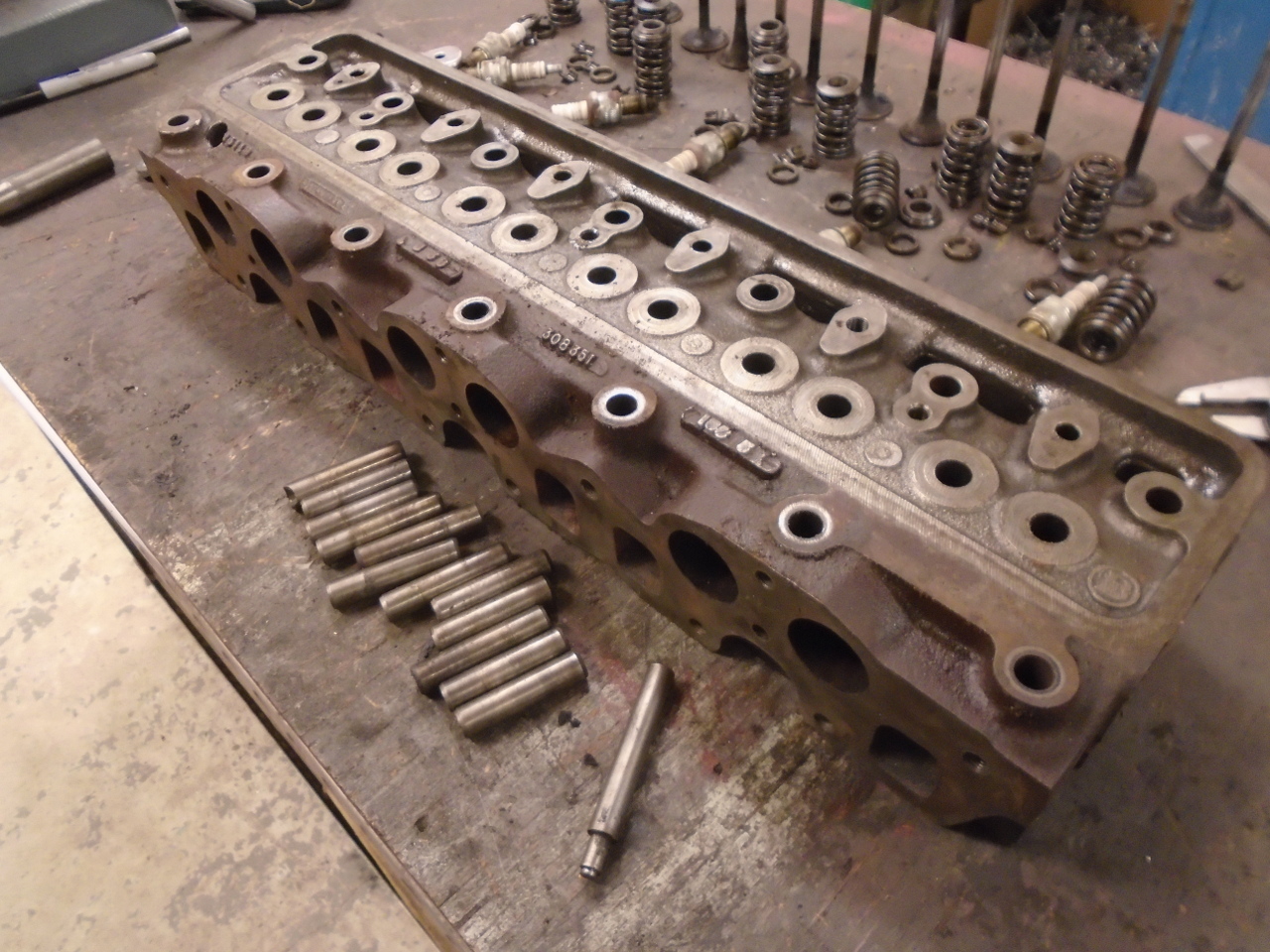
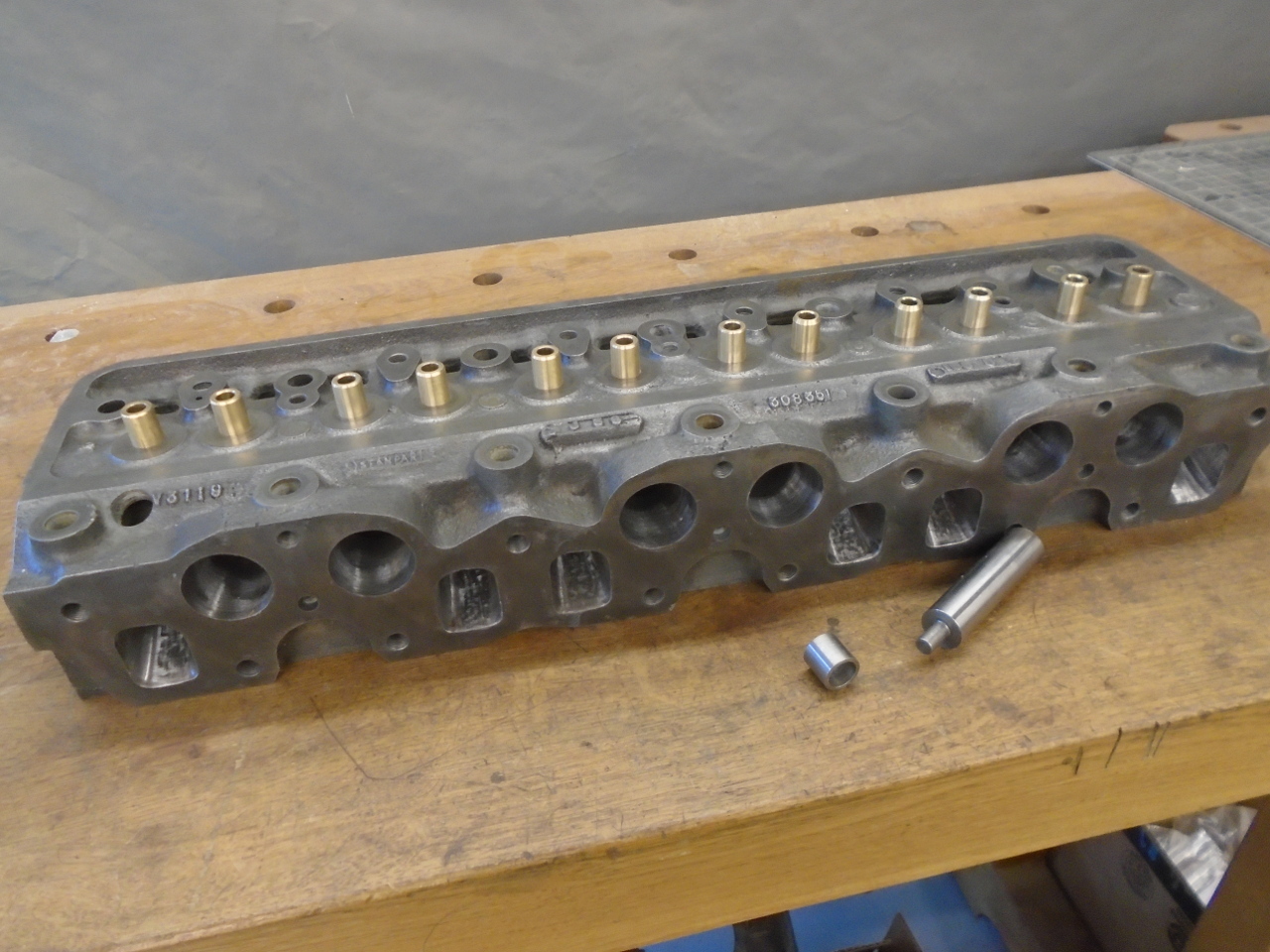
The only remaining removable items on the head were the valve
guides. The valve stems didn't feel too bad in the
guides. The valve stems did measure slightly out of spec
on the small side, but this was compensated for by a "knurl" on
the inside of the guides. According to some notes I found
in my Haynes manual, this is something I had done in the early
80s to address the stem wear. Also, a couple of the guides
were chipped on top.
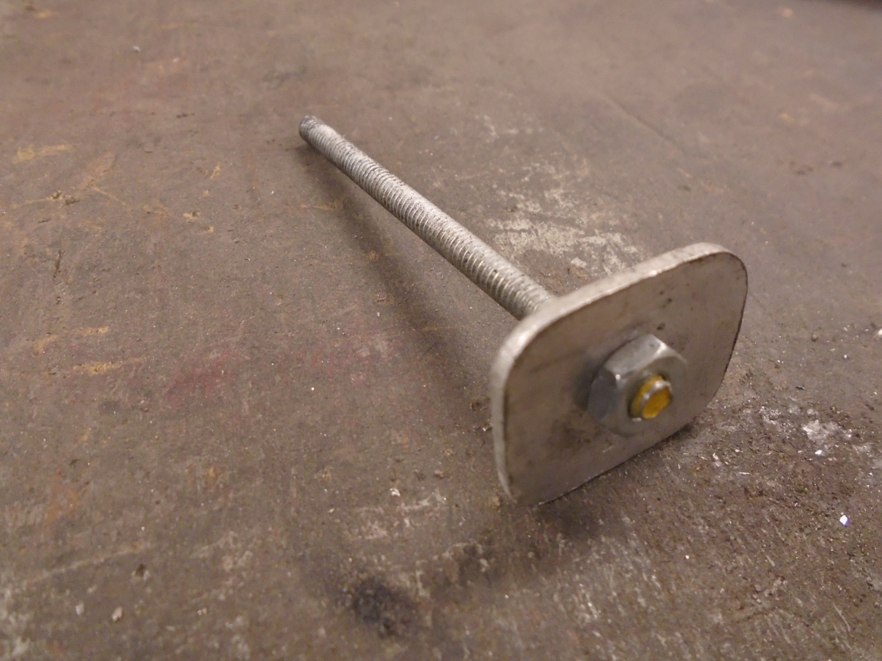
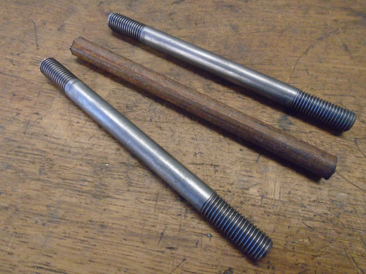
All of this was enough for me to decide to replace the guides,
so out they came. The piece to the right of the guides is
the drift I used to push them out.
So at this point, I had a bare head, and the usual thing would
be to clean it up. It is common to have the things like
this "tanked", or "hot dipped". These processes are
usually a hot caustic solution that dissolves away the burnt,
caked oil, grease and carbon. I've had it done before, and
was often disappointed. It didn't seem to do much for the
rust, or for the internal scale in the coolant jacket.
With judicious choice of chemicals, I thought I might be able to
do as well or better at home.
I took the head to one of those DIY car washes with the high
pressure hot soapy water to clean off what it could--mostly the
oil and some of the carbon. The rest of the carbon and the
combustion chamber deposits came off pretty easily manually.
What then remained was rust and scale, and these things are
better addressed with acids. I made a box, lined it with
plastic, and put the head in it.
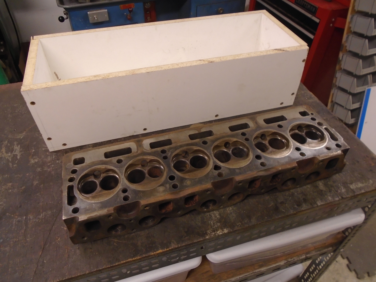
Then added enough phosphoric acid to fill and cover the
head. Though there are stronger, quicker acids, phosphoric
has the advantage of being a little safer to use, and it doesn't
stink.
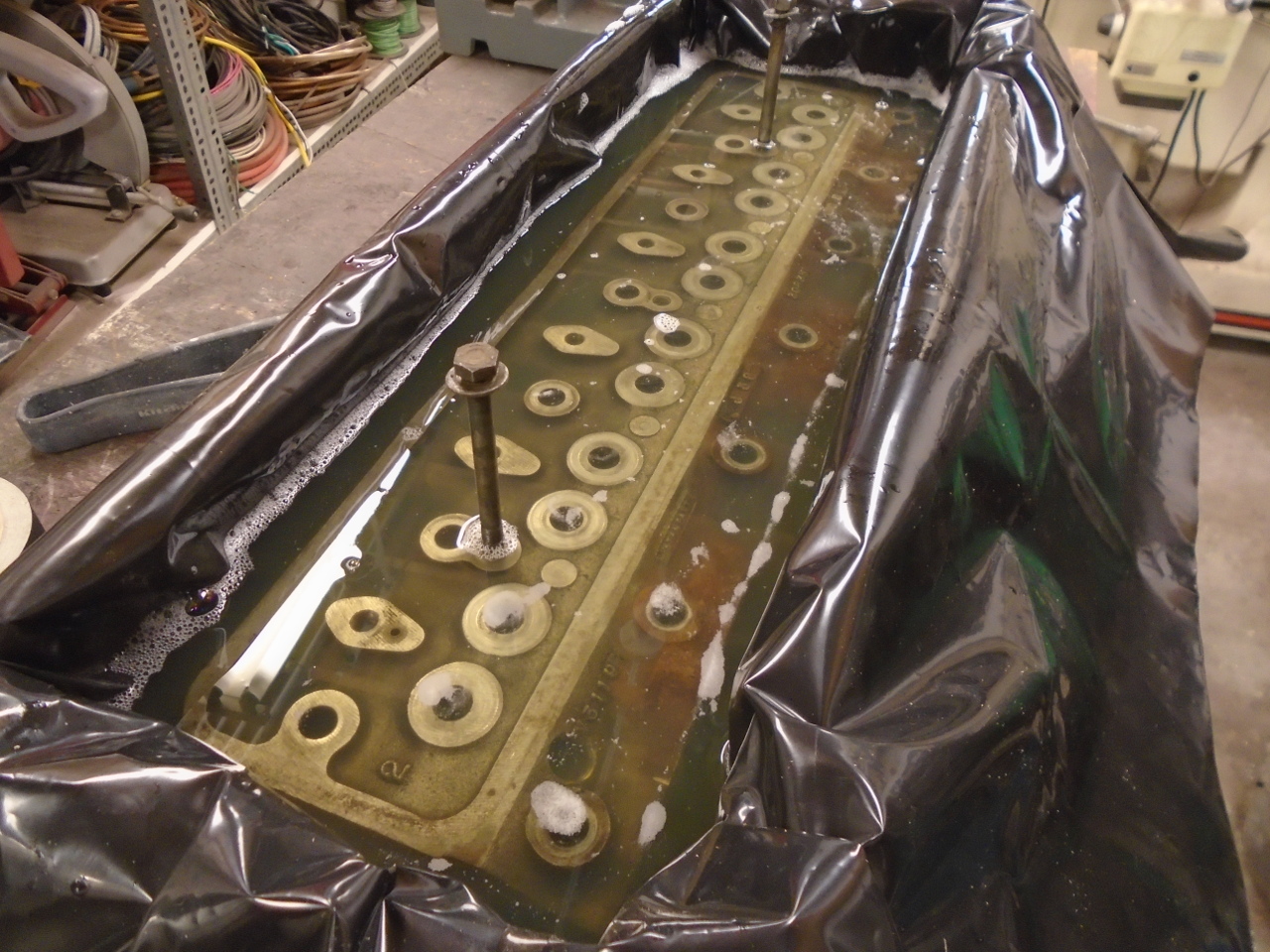
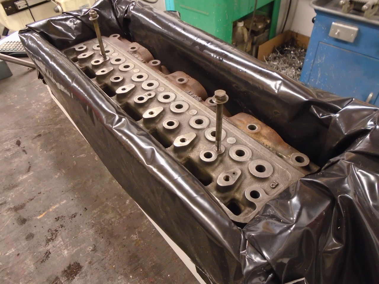
An hour later, the foaming suggested that the acid was doing
something. Phosphoric acid at this concentration has very
little effect on metallic iron, but does attack other
substances. I left the head in the bath over night.
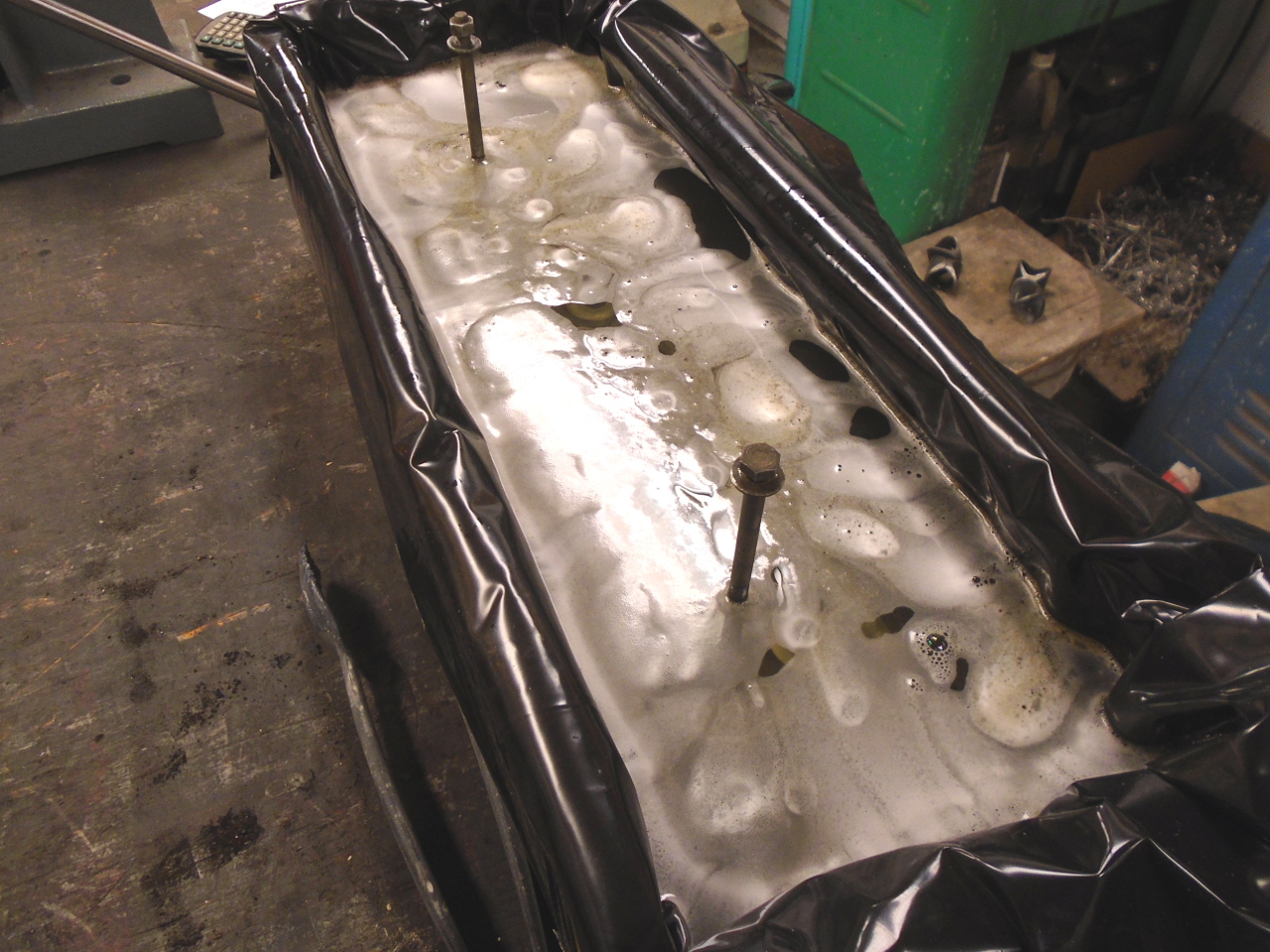
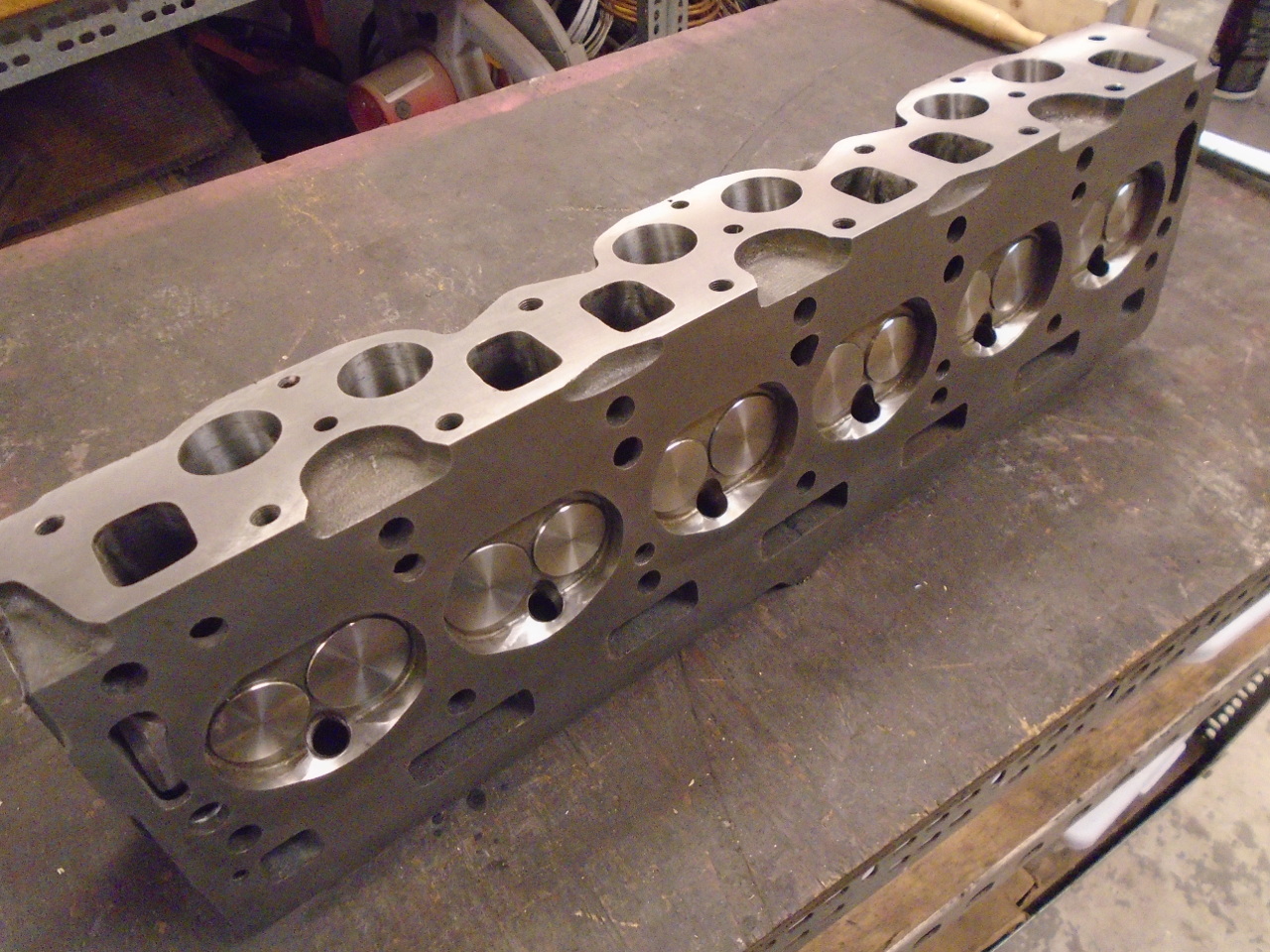
After a rinse and compressed air dry the next day, the head
looked quite a bit cleaner, especially inside.
I had been thinking all through this process about possibly
bumping up the compression ratio a little bit on this car.
I did some research to try to find out what the stock CR was,
and was met with confusion. The ratio varied not only by
model and year, but also my market. I read figures between
7.5 and 9.5. The only way I saw to be sure was to
calculate it myself. One of the most important inputs for
this calculation is the combustion chamber volume, and I'd have
to measure it.
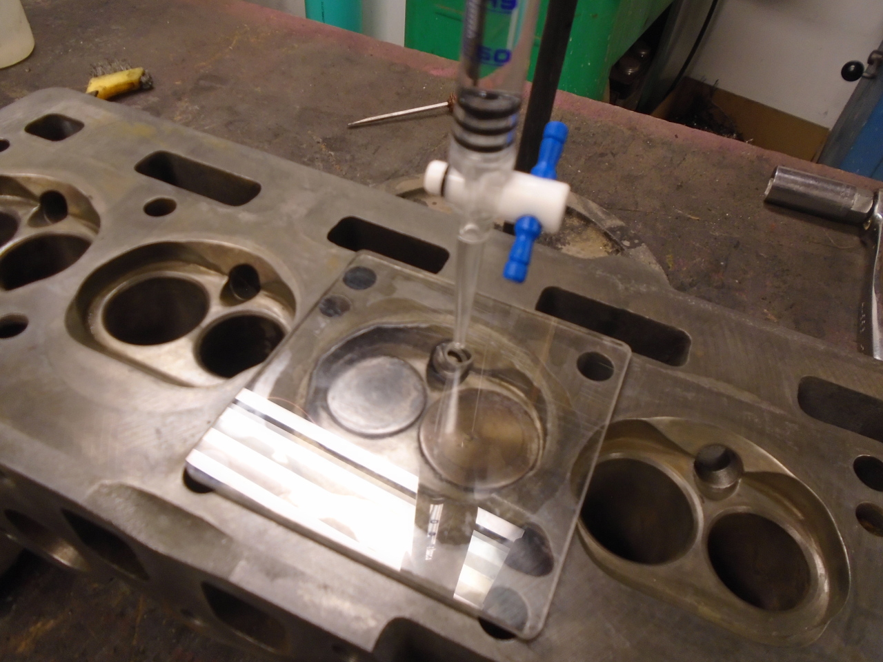
This is not frontier science. People have been doing it
for many decades. It just involves measuring how much
liquid it takes to fill the chamber. Typically, the
chamber is covered with a clear panel and the liquid is added
through a small hole until there is no more air in the chamber.
I assembled the needed equipment and checked a couple of the
chambers. The valves and top cover are sealed with
Vaseline.
The subsequent calculation yielded a compression ratio of a
little under 9:1. However, I had some recollection of
having had the head shaved back in the 80s. Some more
research revealed that the stock head for this car should have
had an overall thickness of 3.300 inches. Mine measured
about 3.290", so it appeared that I'd had about 0.010" taken
off. Working backwards, this implies that the stock car
must have had a CR near 8.75:1.
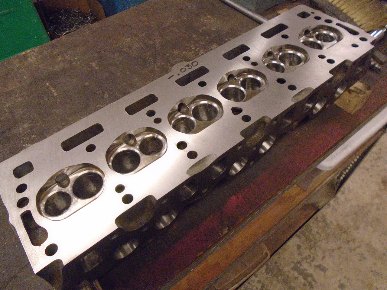
I decided I'd like a CR of around 9.5:1, and calculated that an
additional 0.030" removed from the head should deliver something
close to that. I briefly mulled doing the shaving myself,
but it's a little big for the tooling I have, so I resolved to
send it out. Besides, I certainly didn't have the
equipment to do a three angle valve seat grind, so the head was
going to have to go to the shop anyway.
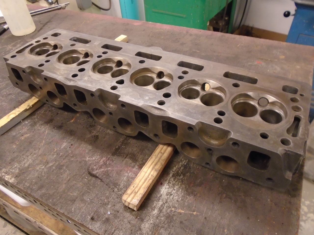
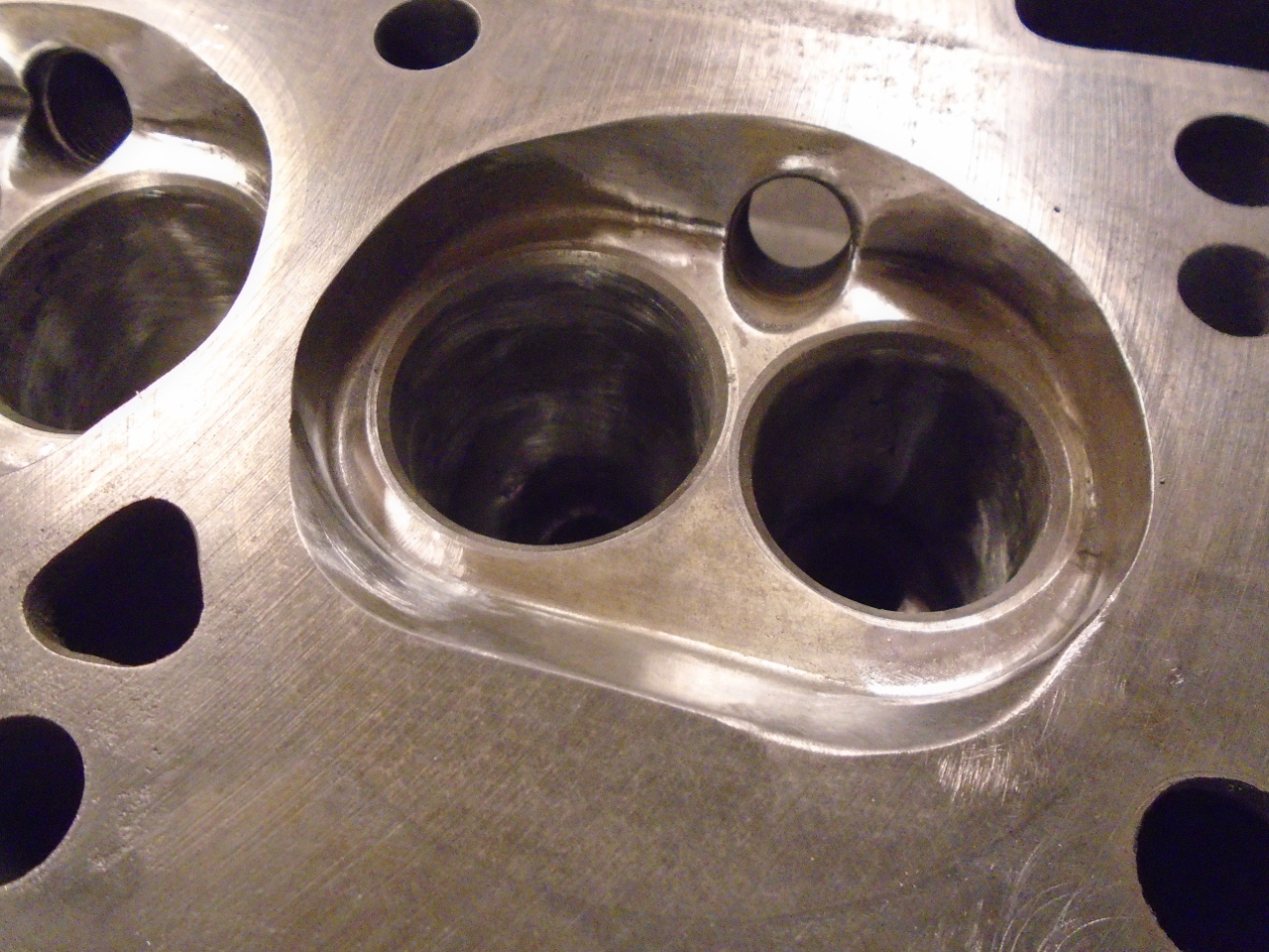
Before hauling the head to the shop, I took a little time to
address a few small mods to the ports and the combustion
chambers.
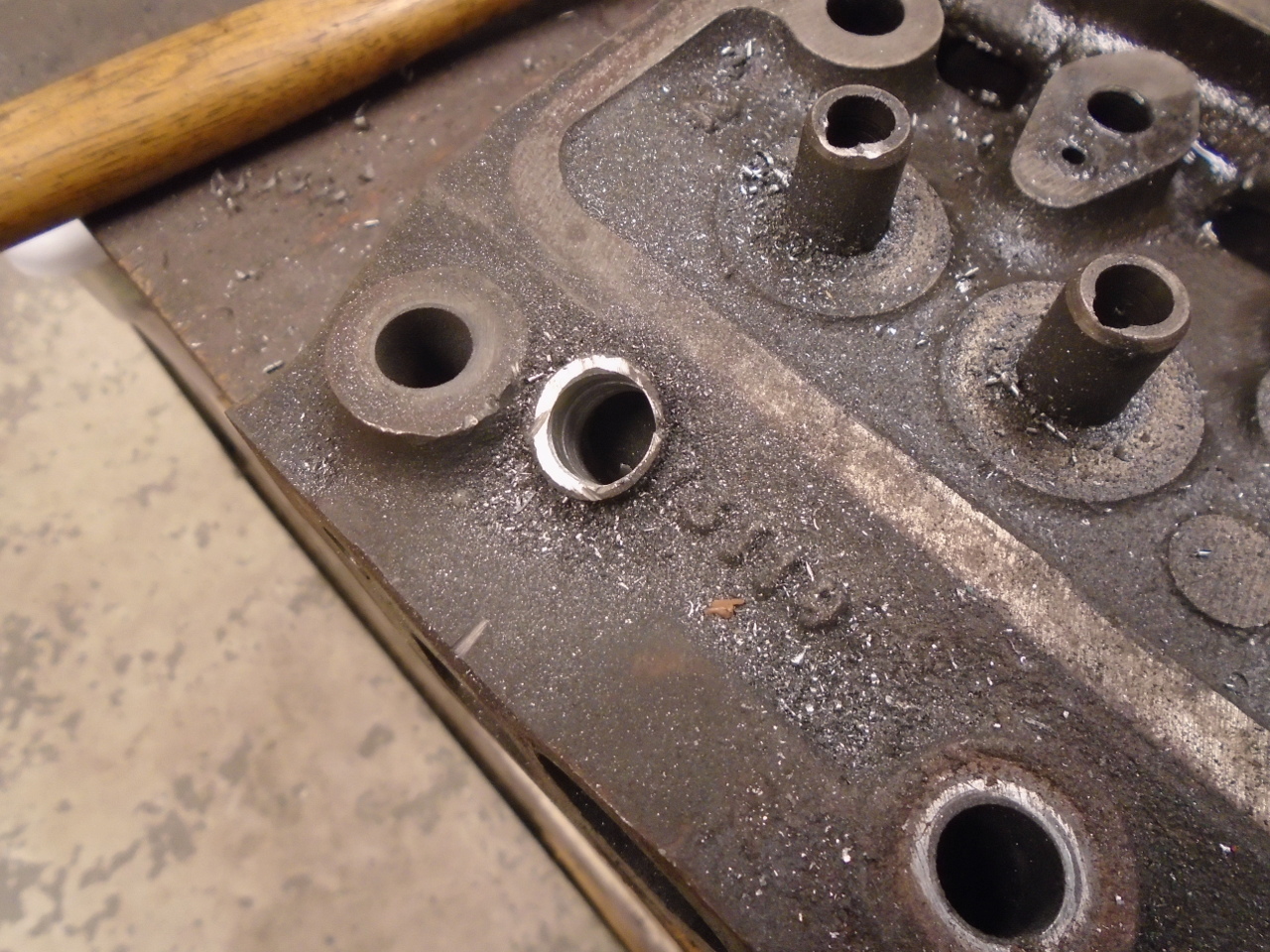
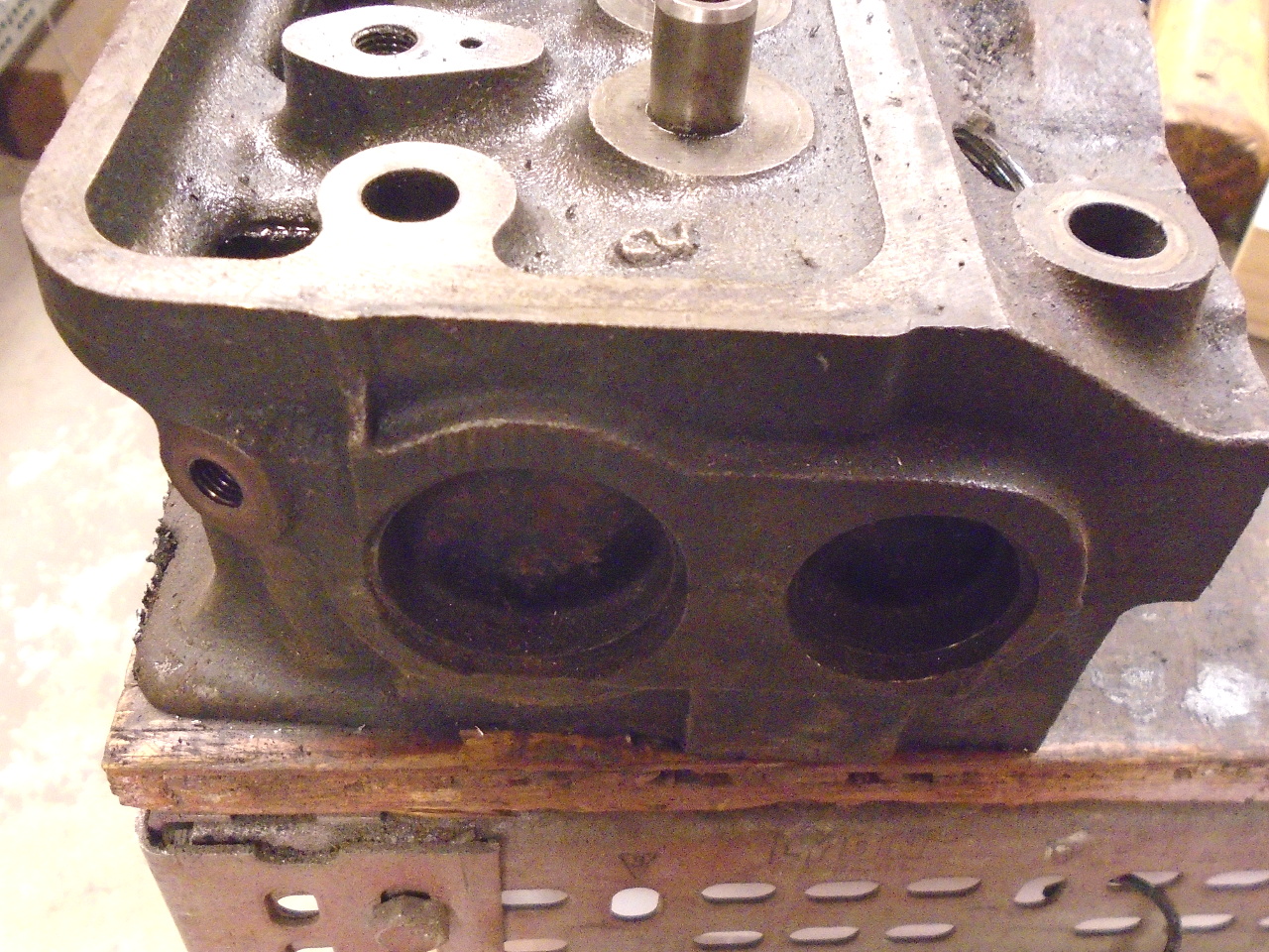
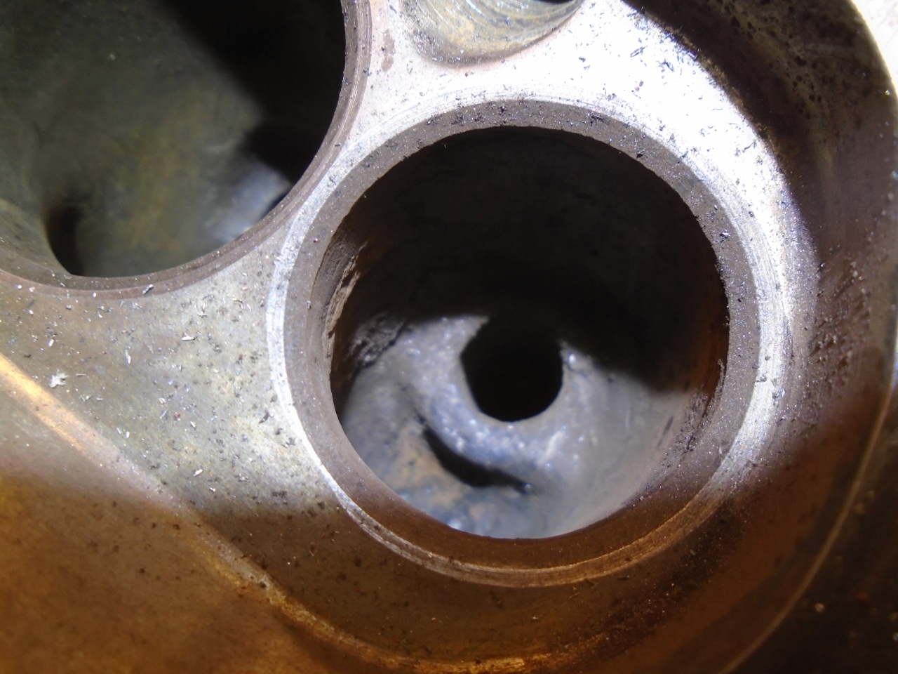
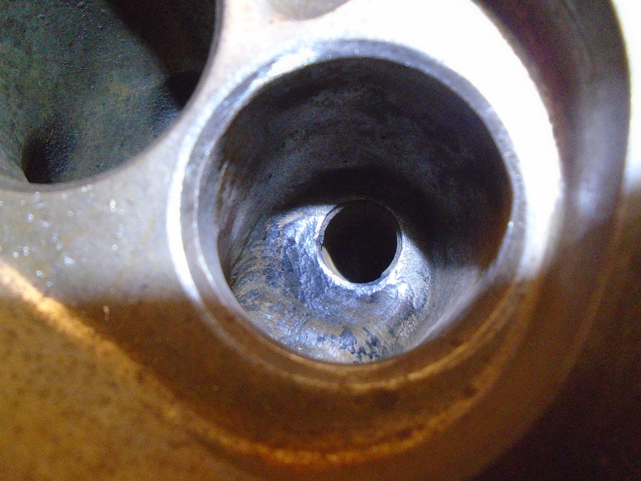
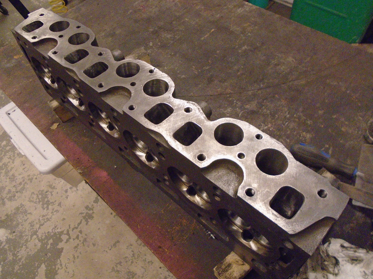
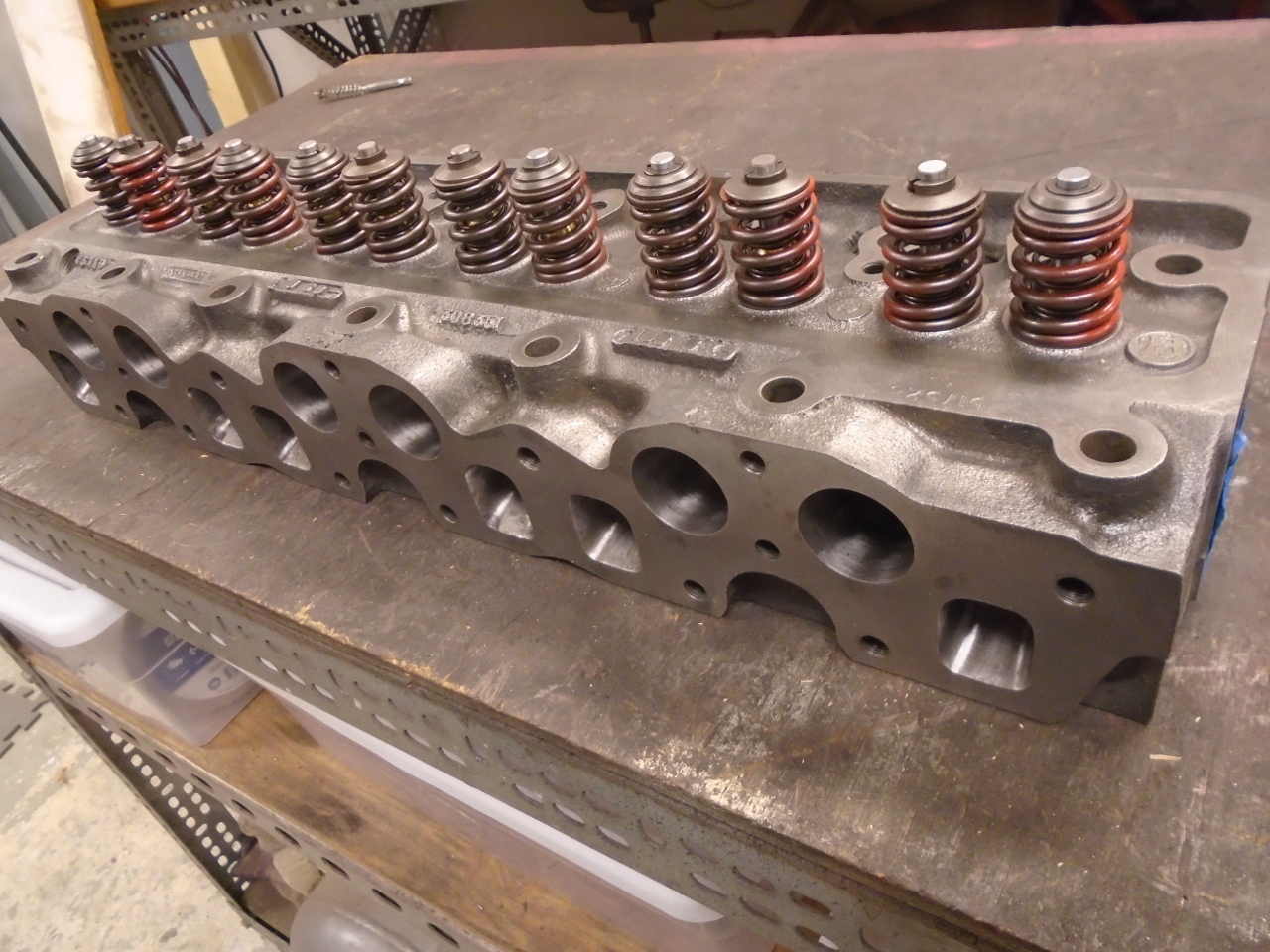
The exhaust ports on this head have a sizeable boss in the roof
of the pocket above the valve. The boss is to support the
lower end of the valve guide. That feature offers some
restriction in flow, and since it is larger than it needs to be,
it's a common mod to reshape it to reduce the restriction.
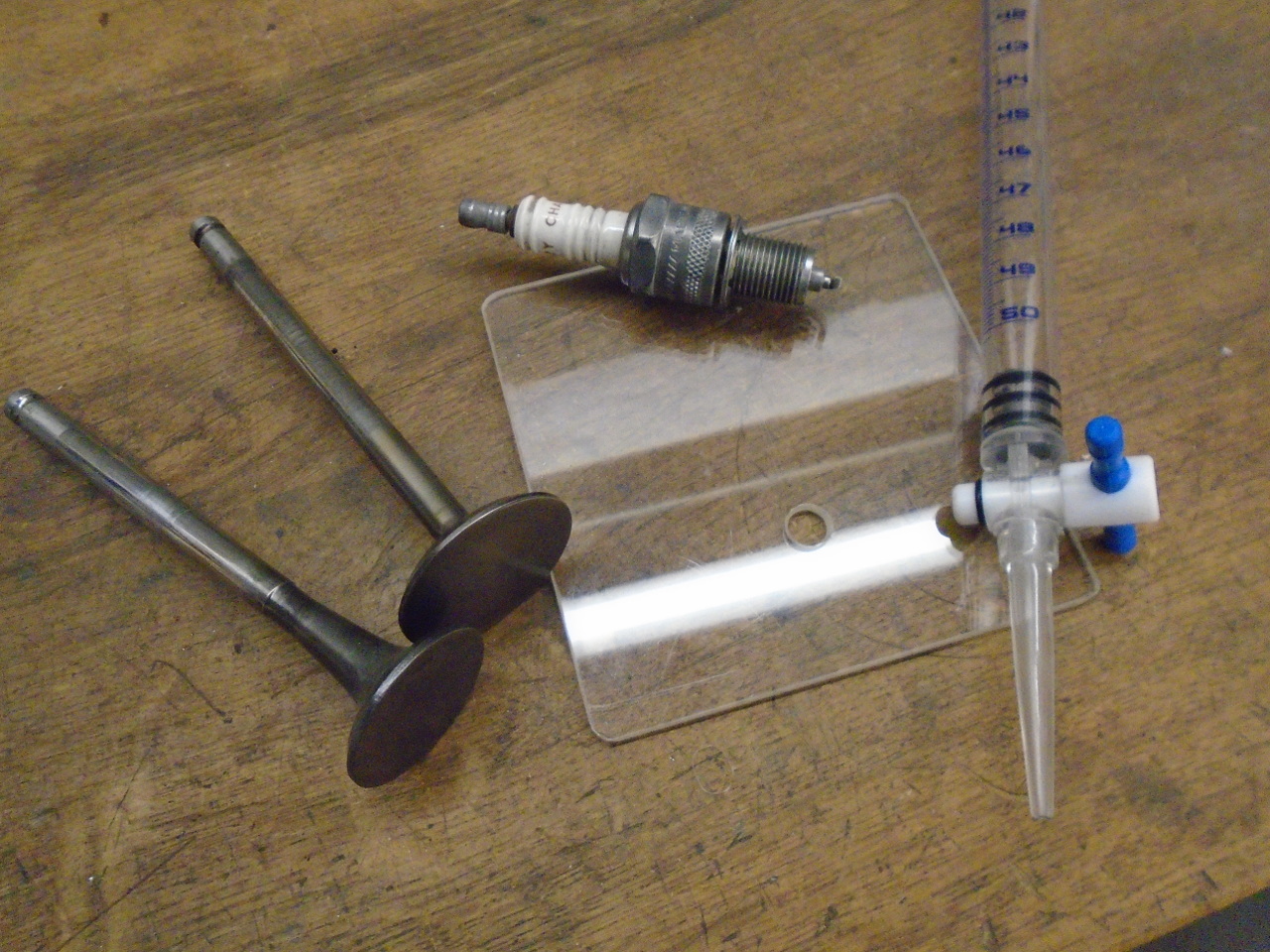
The exhaust ports also got some minor reshaping to maintain a
relatively constant cross section through most of their
length. This little template, which fits the port opening,
was used to determine where to grind. The idea is that the
template should be able to pass through the length of the
port. Something similar was done for the intake
ports. The amount of material removed was pretty minimal.
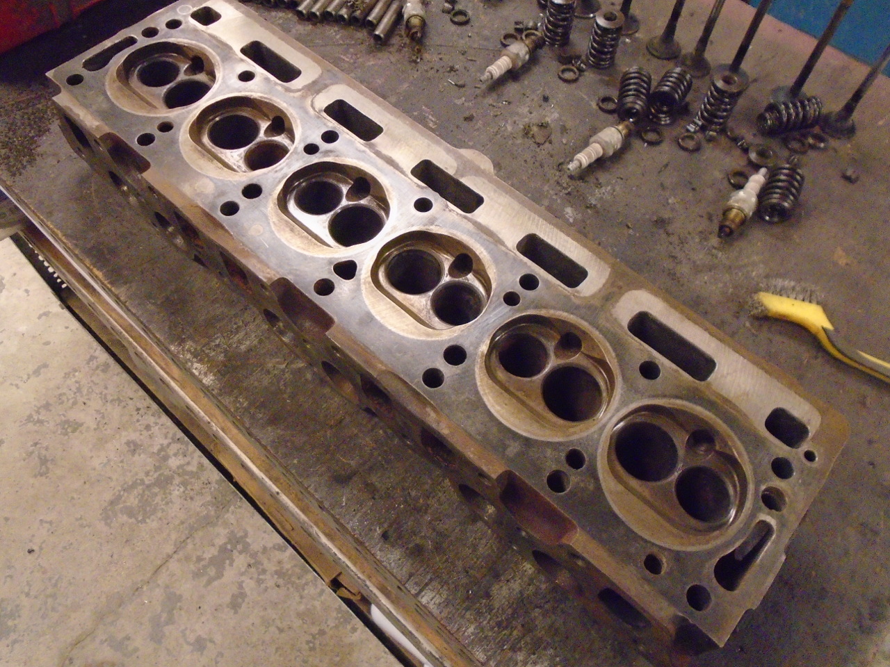
The only other grinding mod to the head was to blunt the
"eyebrows" in the combustion chambers. These are sharpish
"creases" on either side of the spark plug opening, and also on
the opposite side of the chamber. These can reportedly be
hotspots in the chamber and lead to premature preignition.
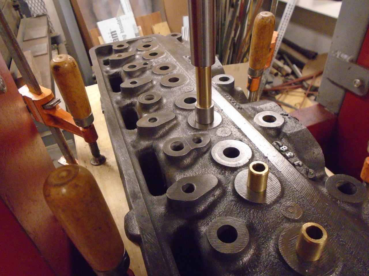
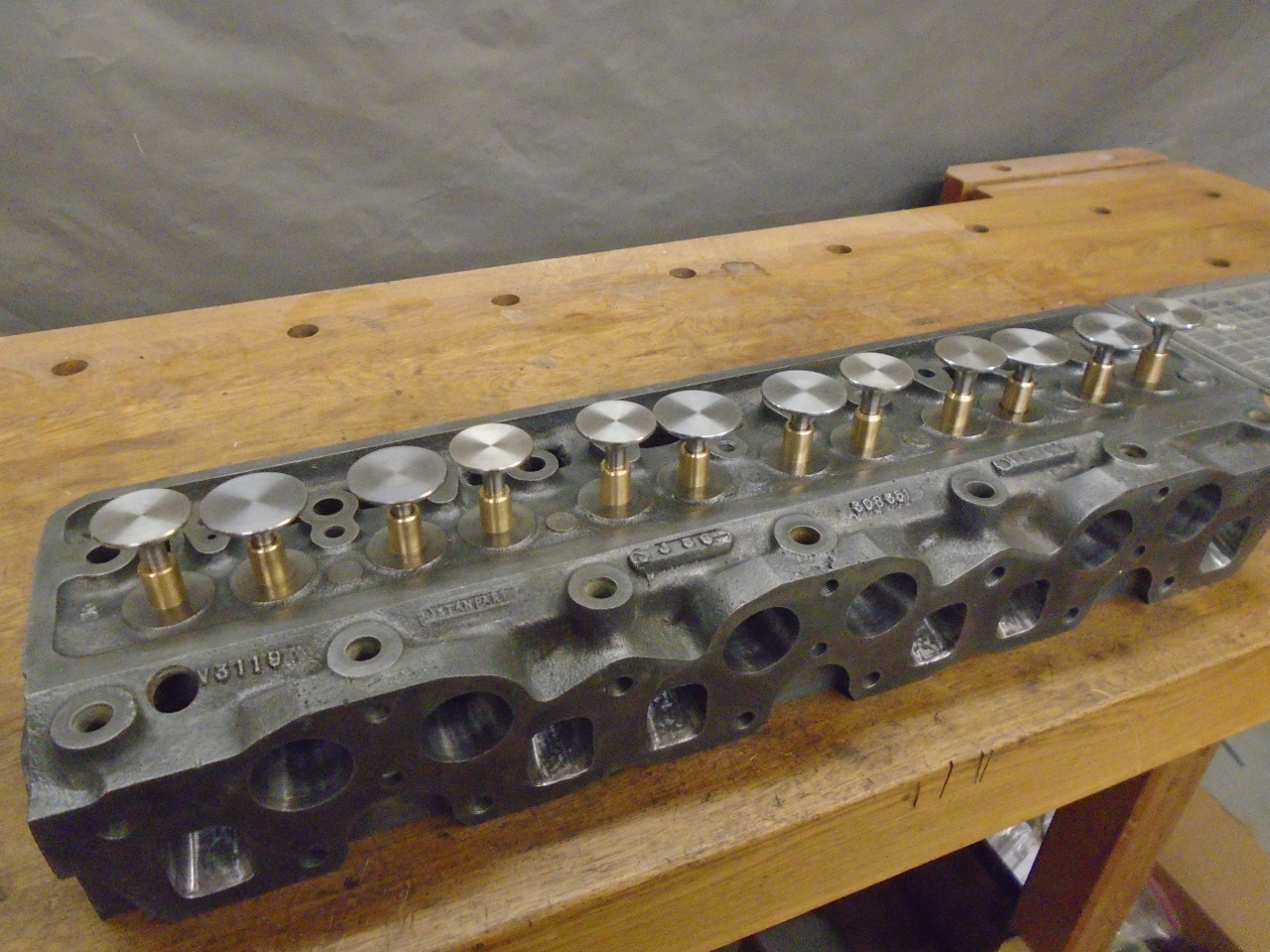
So, it was then time to get the head to the machine shop.
They would need the valve guides installed to to the seat
grinding. I opted for bronze guides because I like the
color.
I consider my Triumph Workshop Manual an indispensable resource,
but have learned that some of the specifications in it shouldn't
necessarily be regarded as gospel truth. For example, the
WSM lists the length of the valve guides as 2.72 inches.
The stock guides on my car were much shorter, and the intake and
exhaust were different lengths. The replacements I bought
matched the stock ones. Also, the protrusion of the guides
above the top of the head face is shown in the WSM to be
nominally 0.750", but my stock guides all had a protrusion of
about 0.630".
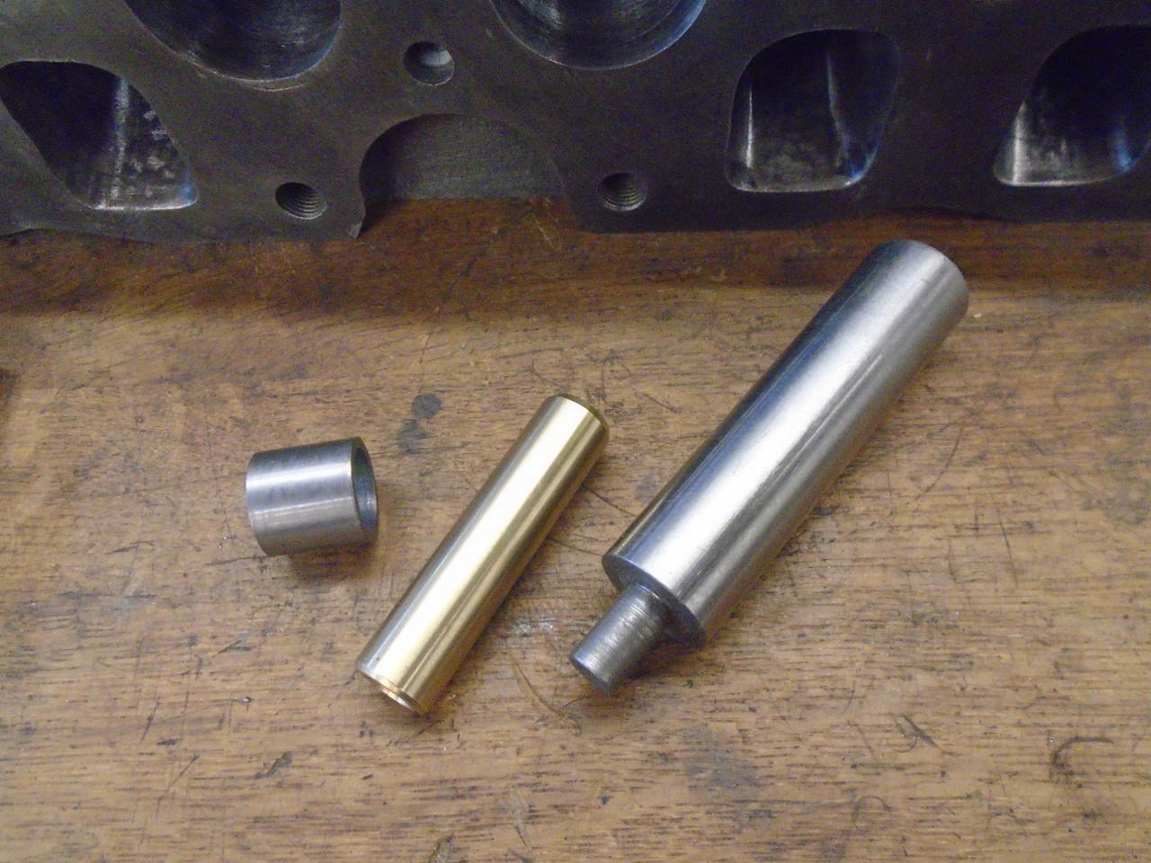
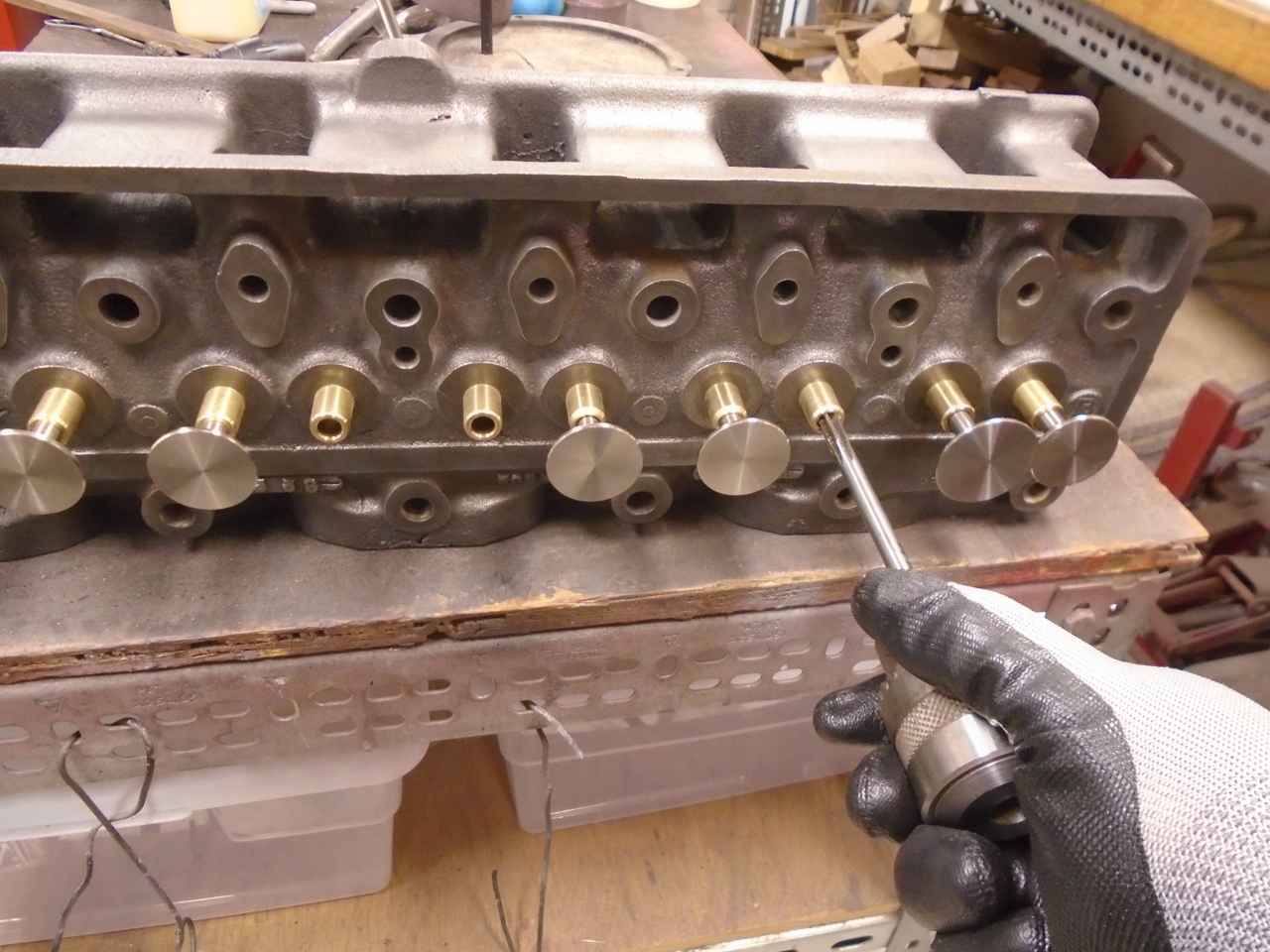
So, I departed from the WSM when I installed the guides.
The first pic shows the drift I used, and on the left, a collar
to limit how far the guides got pressed in.
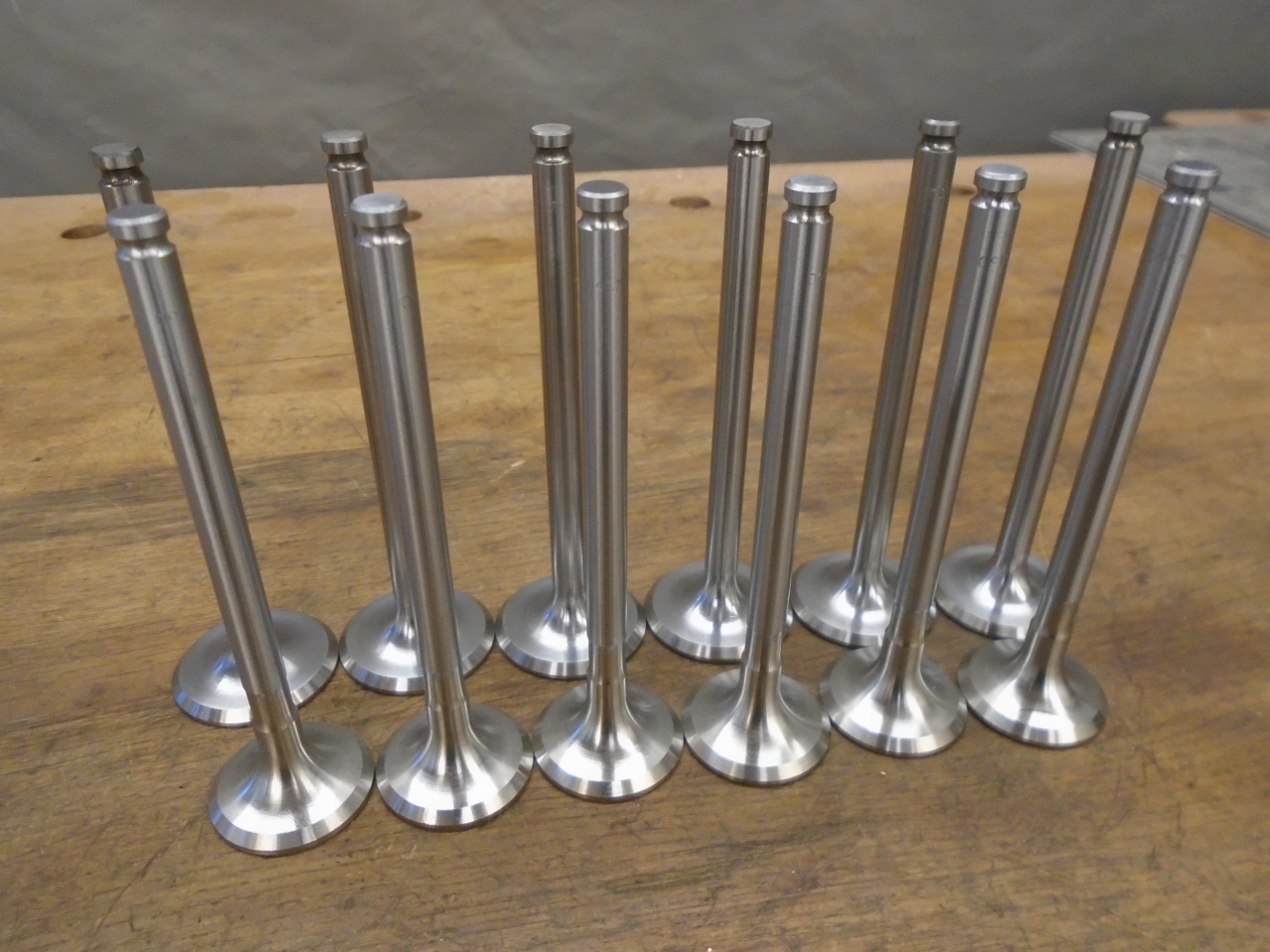
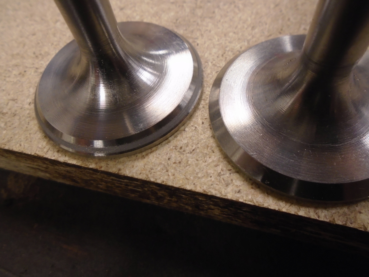
Because of the valve stems being out of spec, I also ordered new
valves. The exhaust valves are stainless steel.
I checked the valve stems in the installed guides and found that
they were all very tight. I fixed this by hand reaming the
bores. Inexplicably, the inlet valve stems are about
0.001" larger than the exhaust stems (the WSM has this correct),
so it really needs two different sized reamers. The
closest I could come was a 0.3120" reamer for the exhausts, and
a 0.3125"for the intakes.
Then, it was off to the machine shop for the shaving and the
seat grinding. Turn around was really fast.
At this point, since I had all of the chamber "cc" stuff handy,
I checked all of the chambers. They were all within about
0.3 cc of the same volume, which is less than 1%. Since
this will be a street car, I didn't stress about the
variation. The new compression ratio calculated to be a
shade over 9.5:1.
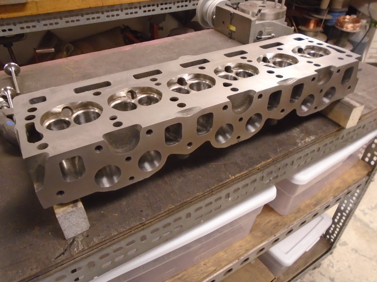
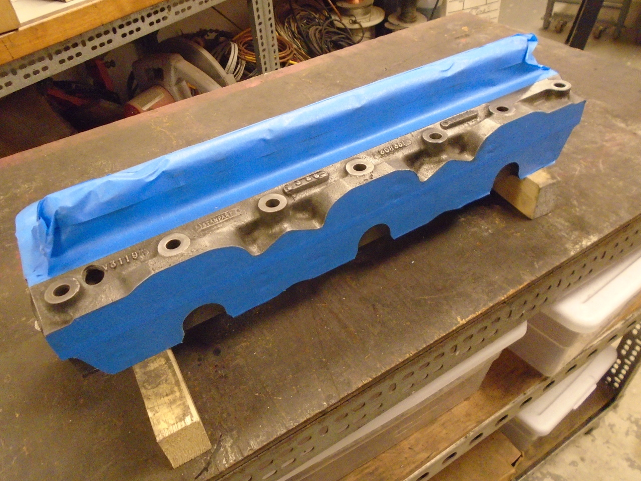
The newly machined surface of the head looked really good.
Unfortunately, it made some of the other machined surfaces look
a little shabby by comparison. The manifold mating surface
had dings, scratches, and dents that were suddenly bothering
me.
Since it is a much narrower surface, and I've never tried it
before, I decided to face that side of the head.
In anticipation of final assembly, I checked out the original
valve springs, and here is another place where the WSM let me
down. It appears that the WSM has the free length specs
for the inner and outer springs reversed, and the installed
length of the springs didn't match my head, either.
Looking past that, I measured the "seat" load of the springs,
using an impromptu lever arrangement.
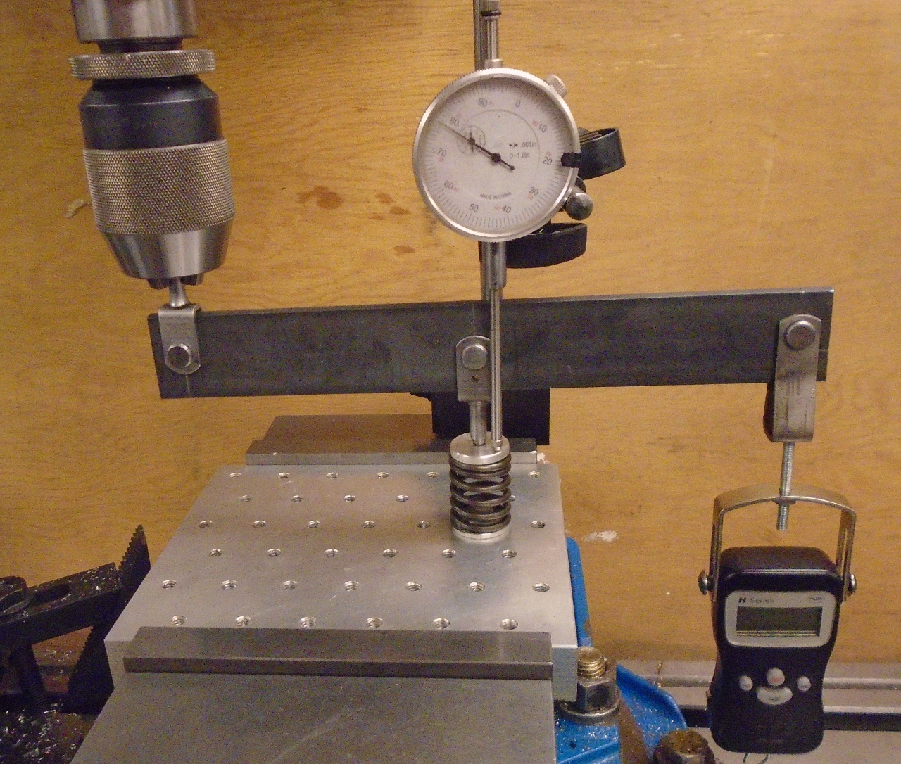
Given the unreliable length specs, it was a little hard to know
what the load really should be, but I concluded that the
measured load was low for both the inner and outer
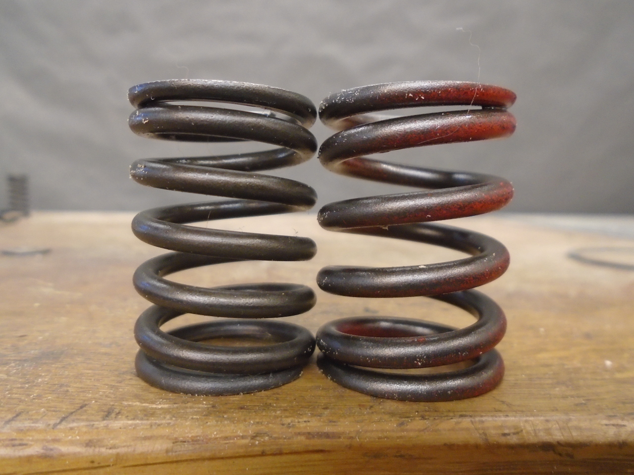
springs. So I ordered new springs. The new springs
will offer quite a bit higher load than the old springs.
Total seat load form both springs will be about 50 pounds.
This is still low my modern standards, but about 13% above the
WSM spec. Most of the extra load comes from the new outer
spring, which has thicker wire and fewer coils than the original
spring (and is wound the opposite way, oddly).
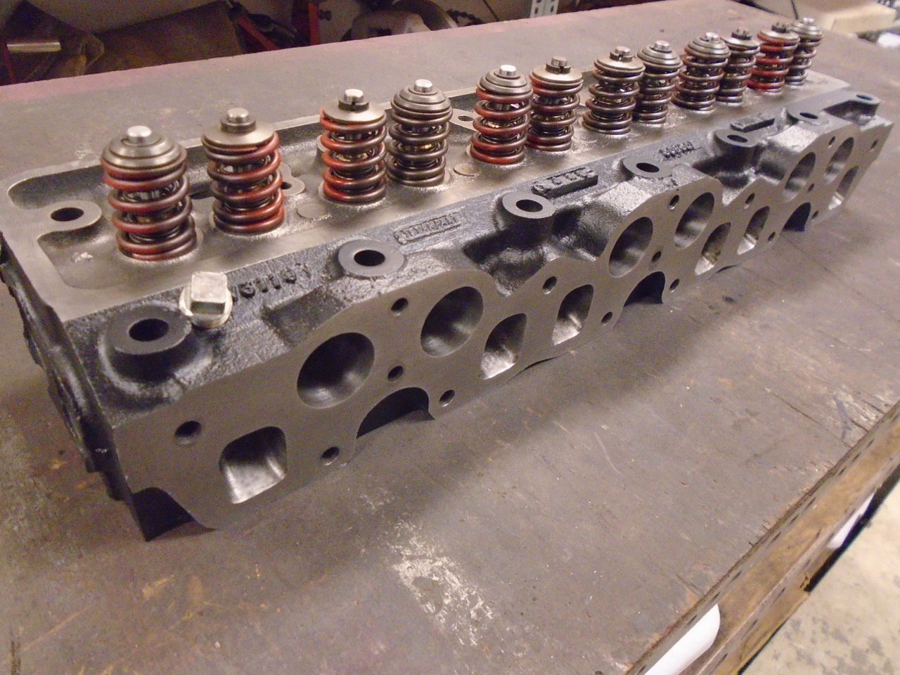
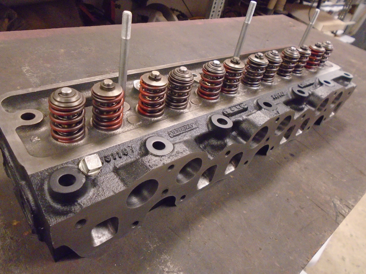
So, assembly time, but first, lap the valves. This ensures
a tight seal.
There are over a hundred parts here...
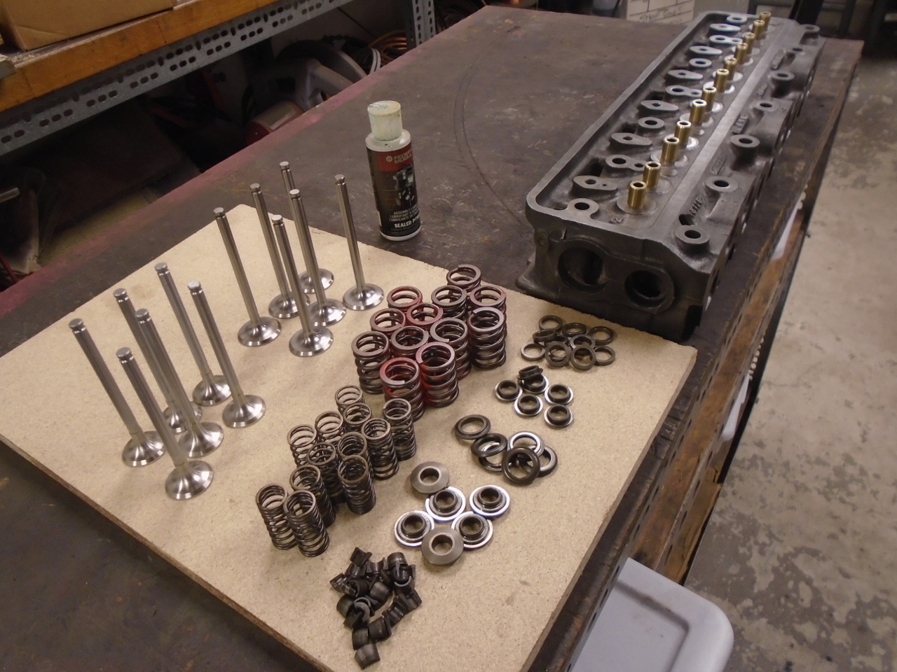
...but they all found a home.
And some paint to make her look pretty.
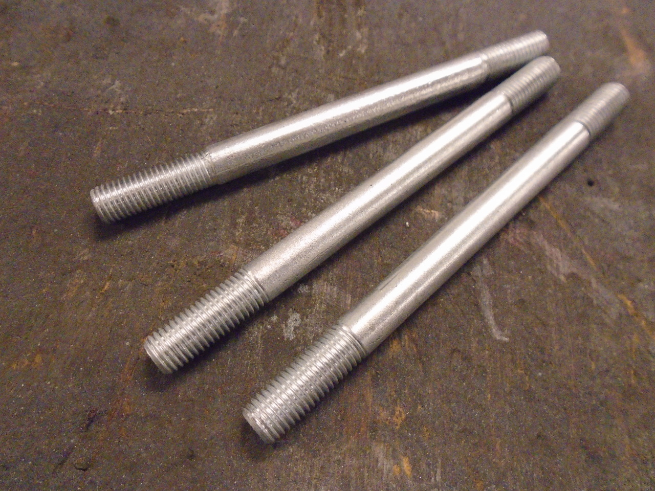
One of the three valve cover studs had long ago been replaced by
a long bolt, so this was my chance to make it right.
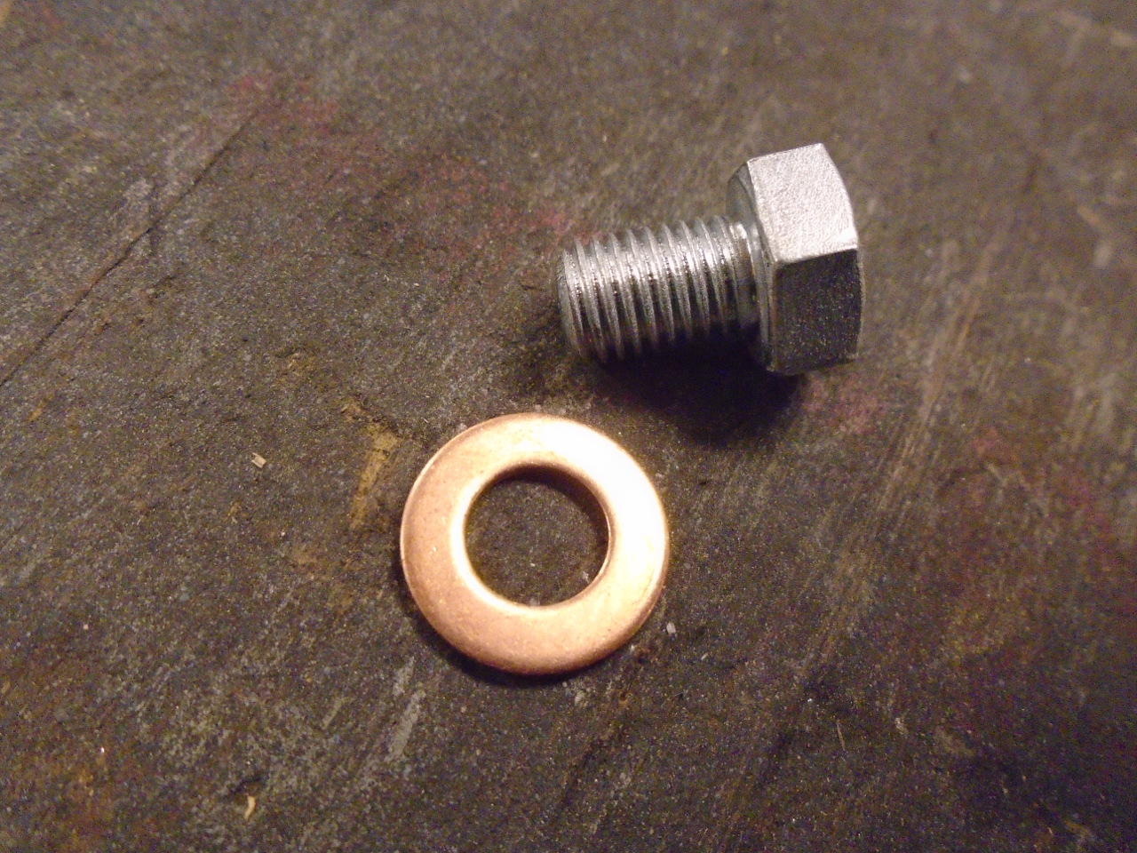
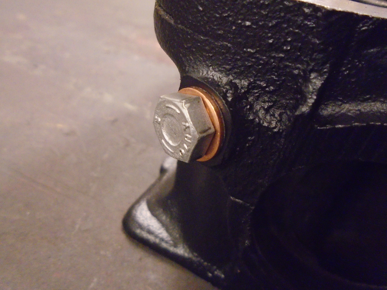
And then to take care of a couple of details that I almost
surely would space off before first startup.
On the shelf until I'm ready for it.
A lot of steps in this project, and a lot of repetition.
Also, one of the more expensive ones at around $350 for the
valves, springs, guides, and the machine work. Can't wait
to install it.
Comments to Ed at elhollin1@yahoo.com
To my other GT6
pages