To my other GT6
pages.
October 31, 2020
Crank, Rods, & Pistons
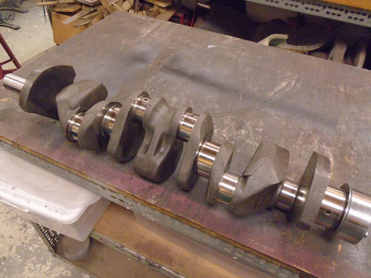
When I did a cursory rebuild of this engine in the early 80s, the
machine shop I took my crank to told me that is was still in spec,
so I just had the journals polished. Now, nearly 40 years,
but less than 10,000 miles later, I didn't expect much
change. As expected, the journals still looked very good,
and I measured them to still be within factory spec. This
was obviously good news. Other than general cleaning and
swabbing the oil channels, I did do some minor touch up polishing
in a few places.
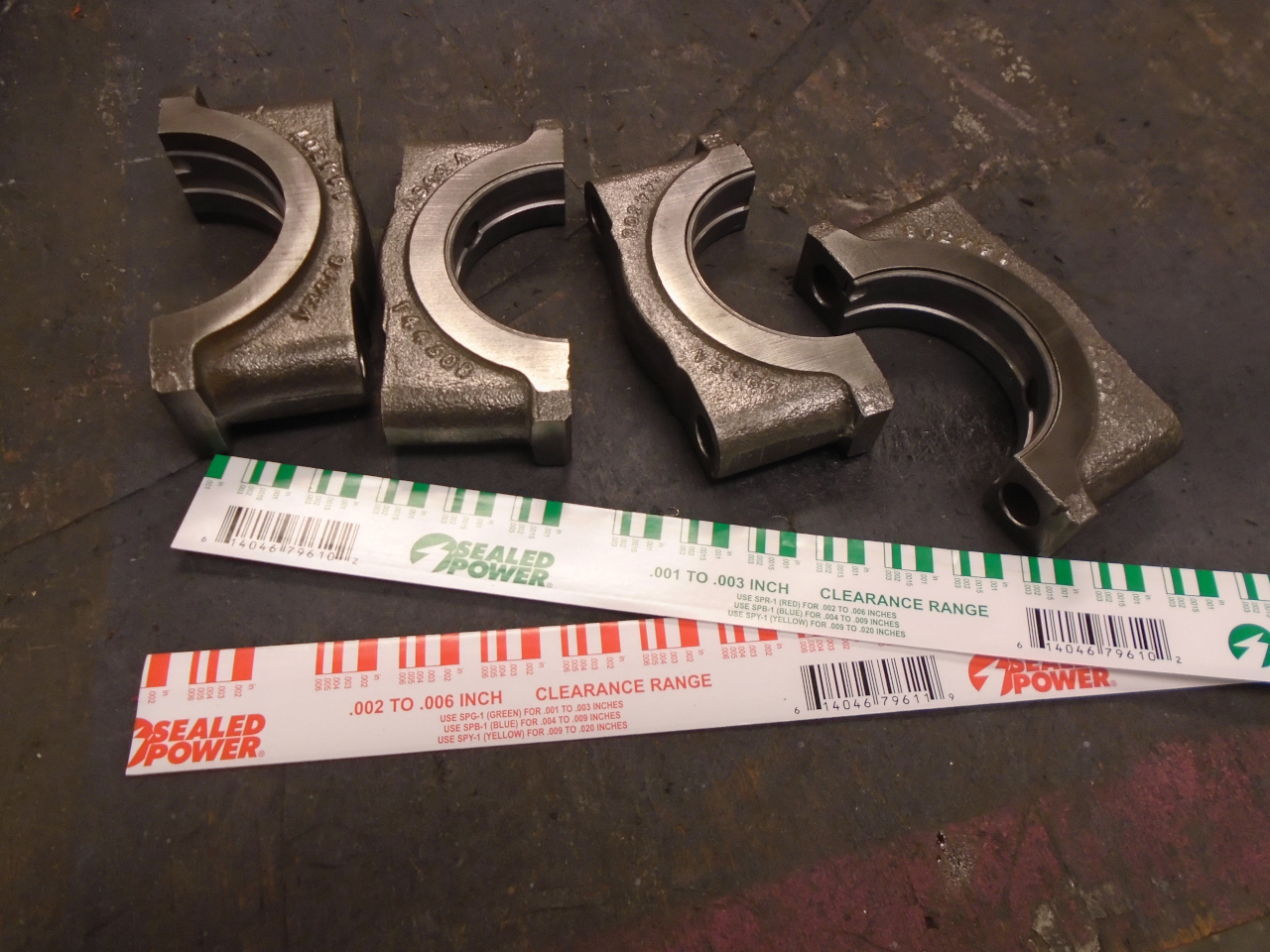
I probably could have even re-installed the main bearings, but I
mixed them up, so I just got new ones. As a double check, I
used some Plastigage to verify the clearance. It came out a
little under 0.002", which seemed OK to me.
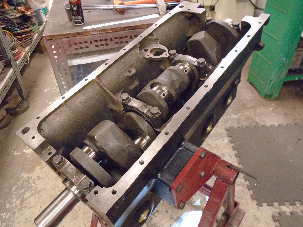
I installed the crank with some nice assembly lube. All
torqued down, the crank was still easy to turn by hand.
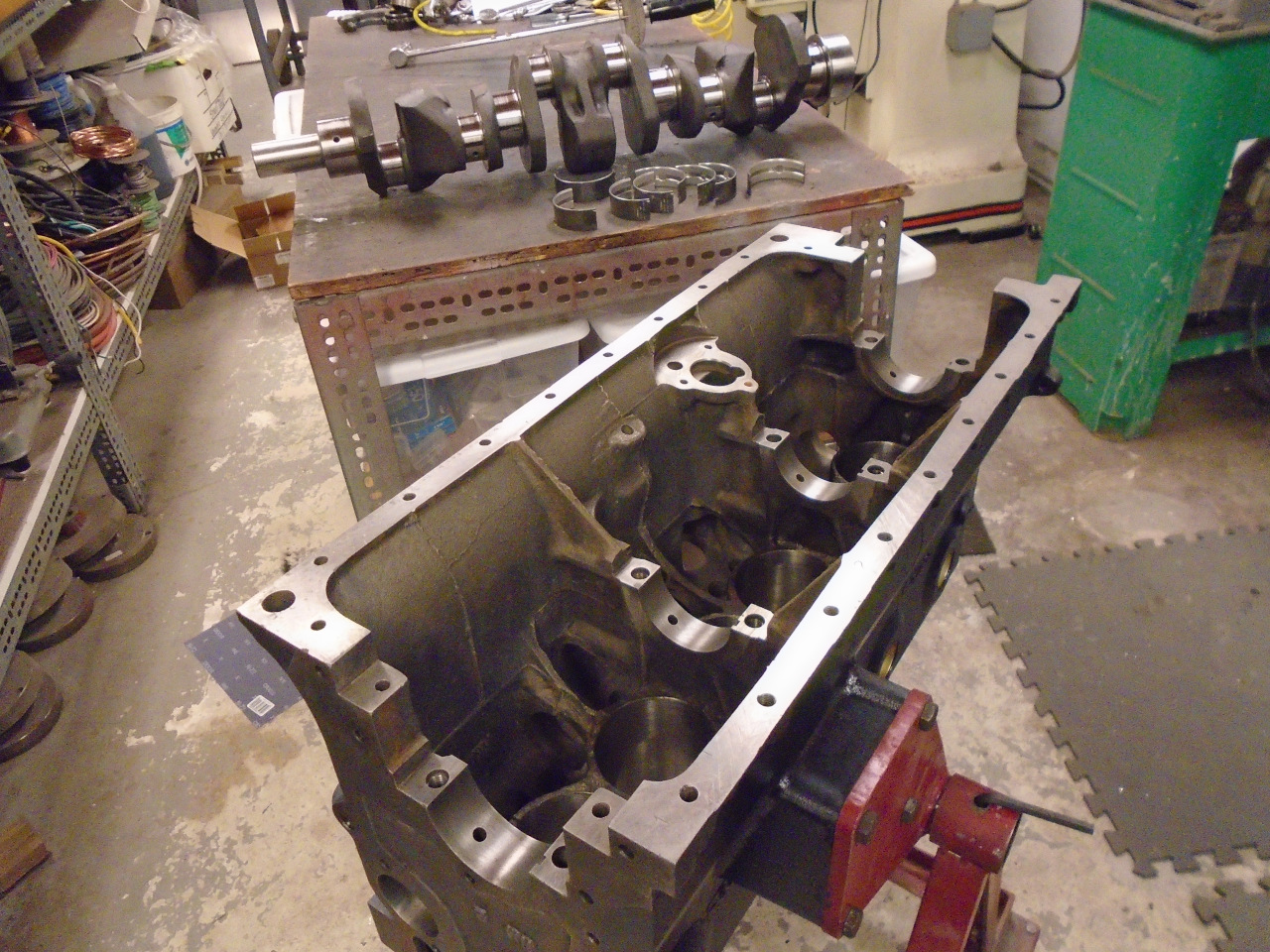
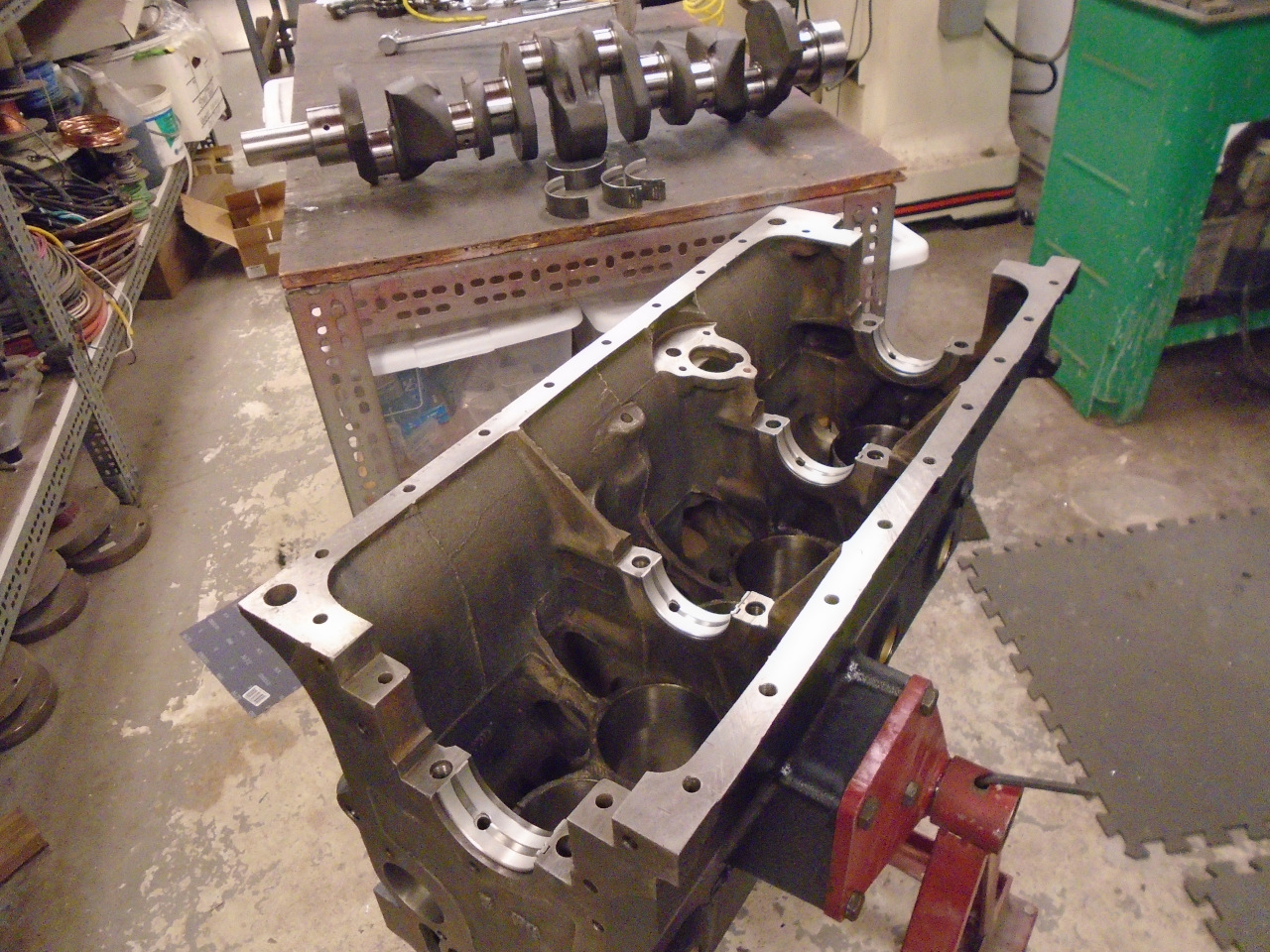
At this point, I realized that I'd forgotten to install the thrust
bearings. These bearings take the end-to-end force of the
crank, and control how much it can move on that direction. I
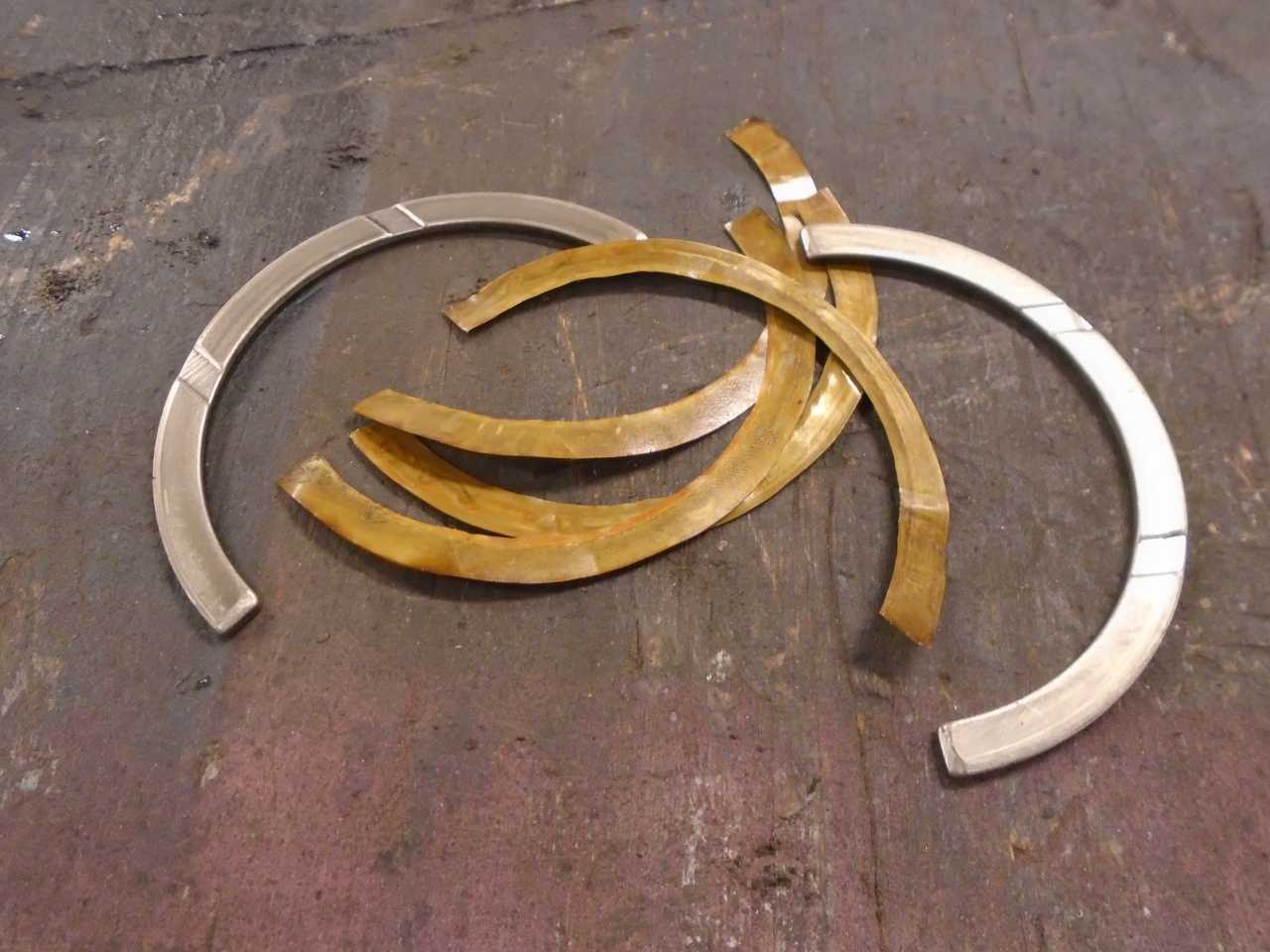
retrieved the baggie that held the thrust bearings I
removed. In the bag was a pair of standard-thickness
bearings, plus four 0.002" brass shims. I assume it was the
younger me who was responsible for this, and I had a little twinge
of admiration for him because I couldn't really see anything wrong
with the idea.
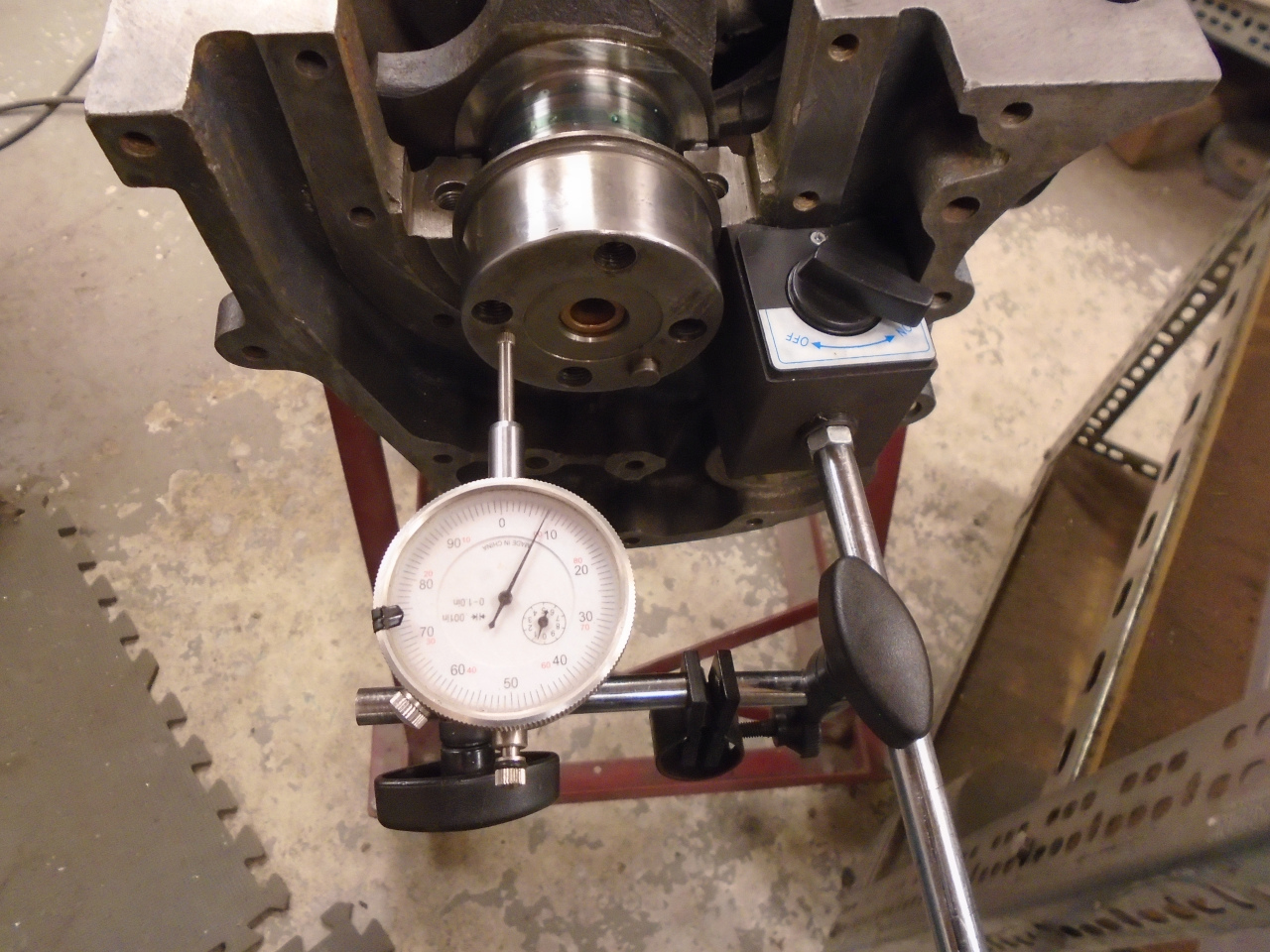
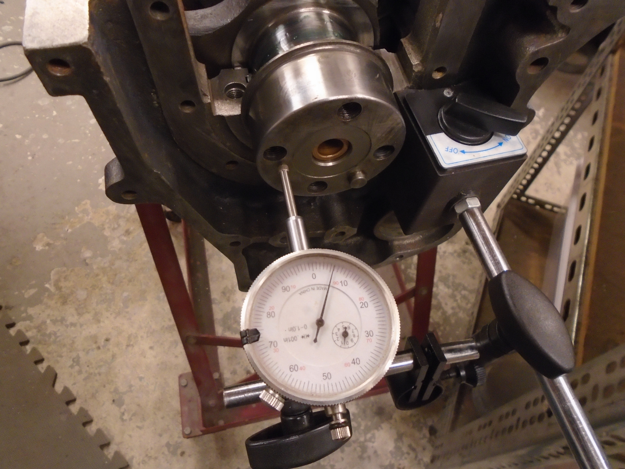
Fortuitously, I had a standard and a +0.005" thrust bearing left
over from my TR6 rebuild, so I installed those and measured the
crank end float, which came out to 0.008". This meets
factory spec, but is the maximum recommended. So, as a
little homage to my 80s self, I popped in one of the brass
shims. This brought the float to 0.006", which made me
happier.
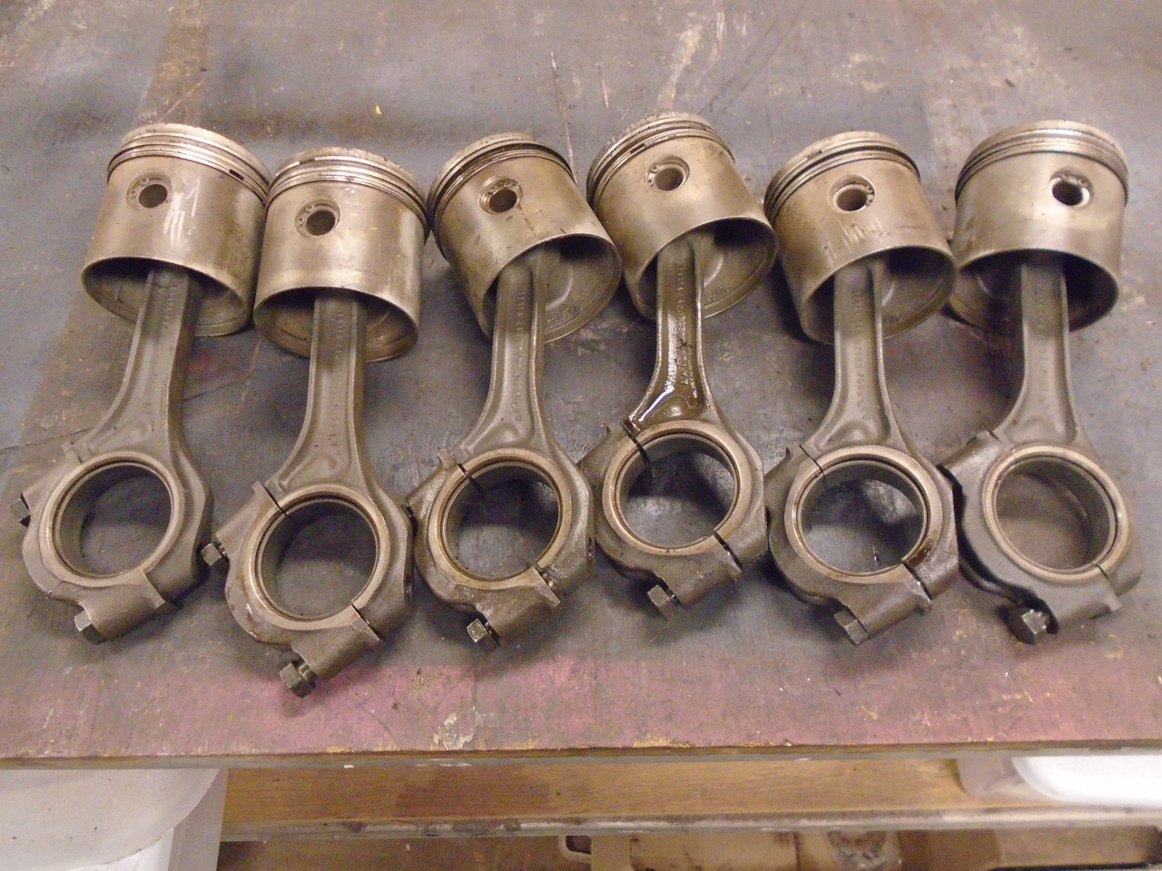
Next up were the pistons and rods. Because of the +0.020"
re-bore, the old pistons would not make the team, but the rods
would, providing there as nothing wrong with them. A quick
check on a flat plate showed that there was no obvious bend or
twist to the rods.
It was at about this time that my Inner Engineer woke up.
"Dude! You need to balance those rods!"
"Really?" I said, rolling my eyes. "This isn't a race car,
you know."
"Doesn't matter, Dude. It's the right thing to do," he said,
jabbing his finger towards me.
"OK, OK. I'll weigh everything. Happy?"
"No! The rods need to be balanced end-for-end."
"What do you mean, end-for-end?"
"Dude! You're losing your skills! The big ends of the
rods rotate with the crank. If they aren't all the same, the
crank balance will be off. You need to make all the big ends
the same weight. The small ends reciprocate with the
pistons. Everything up there in the pistons really should be
the same, too."
"This sounds like a lot of work," I protested, meekly.
"It doesn't have to be. Just use that brain of yours, before
it completely wastes away."
Well, that seemed unnecessarily harsh, but I couldn't deny his
point.
I did a little research on rod balancing. I could buy a
fixture to do it, but they seemed overpriced. There were DIY
versions, but they seemed overly complicated.
What we really need to do is determine the weight of each end of
the rod, but there is a little more to it than just putting the
big end on a scale, then the small end. If the rod is not
level, that is, if the line between big and small end centers is
not horizontal, weight will be shifted to the downhill end.
The commercial and DIY jigs do this leveling with adjustable
hangers or chains.
"But, Dude!" piped up Inner Engineer. "You don't need a universal
rod weighing jig, you just need one for these rods."
"Right!" I replied. " So I just need some sort of fixed bracketry
for these rods. I can measure the rods, do a little
arithmetic, and get the dimensions I need..."
"Now you're firing on all six!"
"...then fab something with aluminum or something."
"Misfire! What about that fancy 3D printer of yours?"
"Of course!" I said. "I'll fire up some CAD."
So and hour or so of CAD and five more of printing (when I could
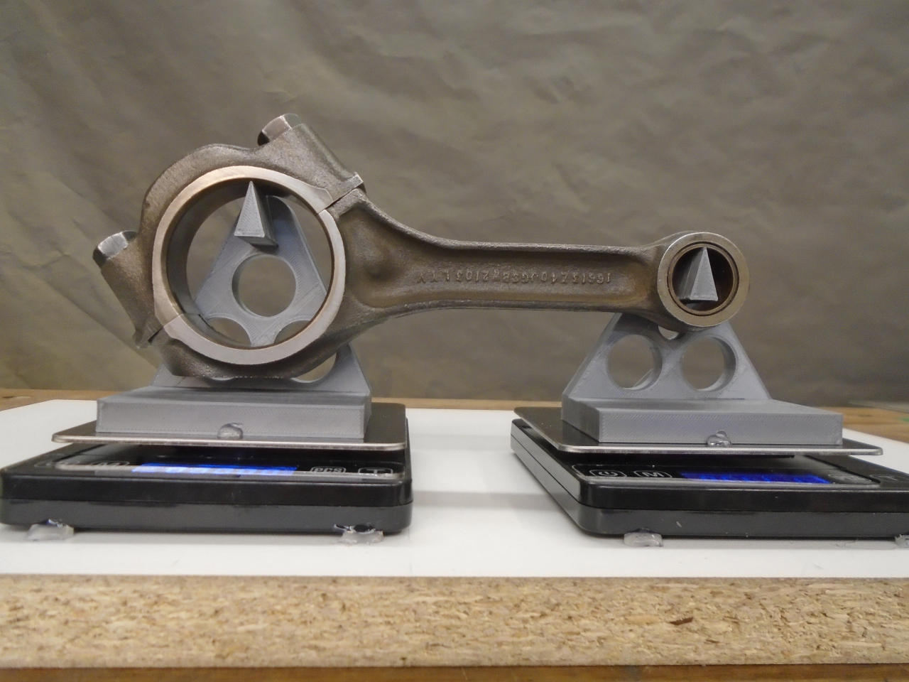
be doing other things), I had these:
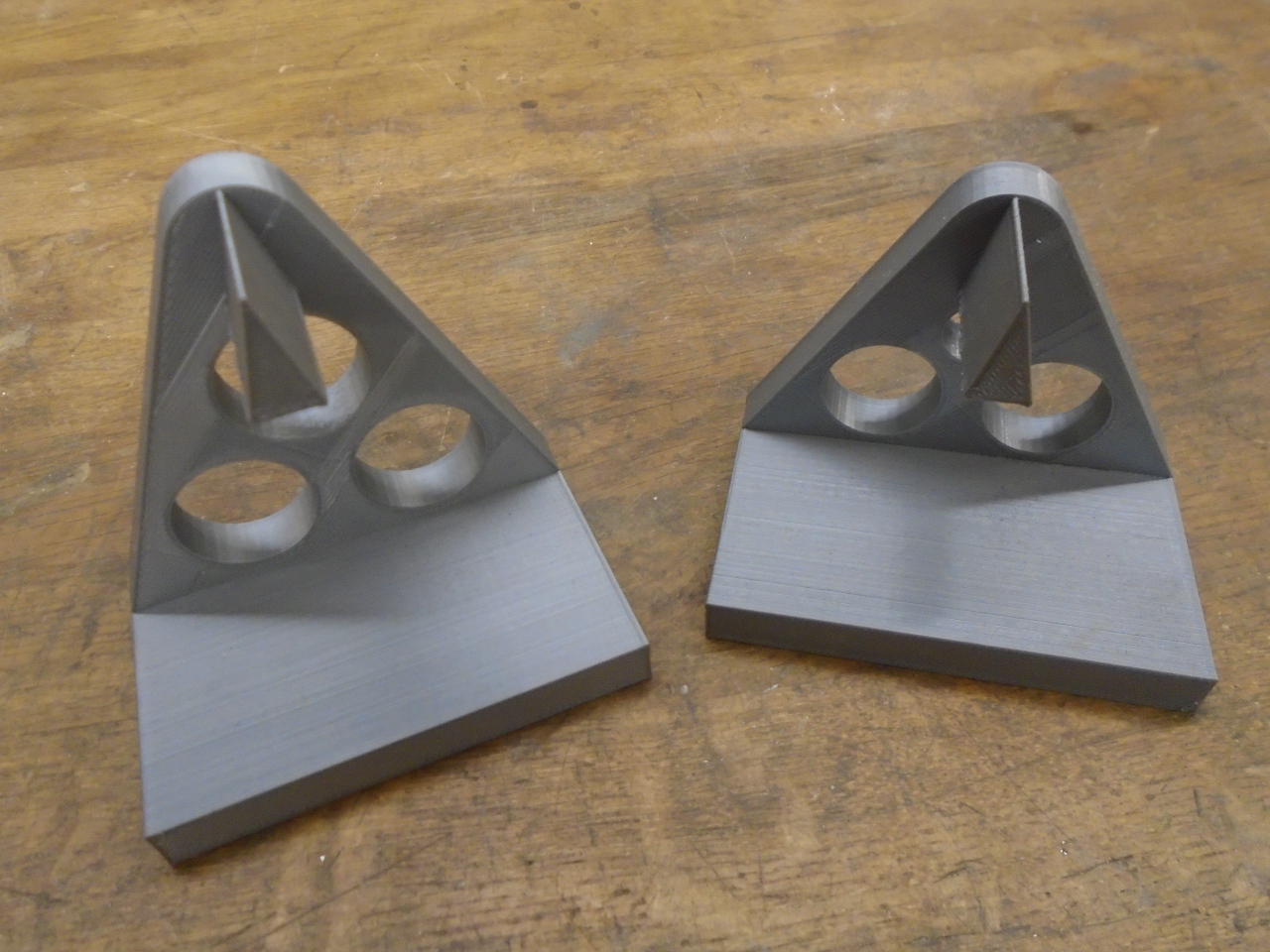
The knife edges would hold the rods from the inside of their
bores. The difference in height of the knife edges accounts
for the different bore sizes. Tall bracket for the big end,
short one for the little end, and the rod will be suspended level.
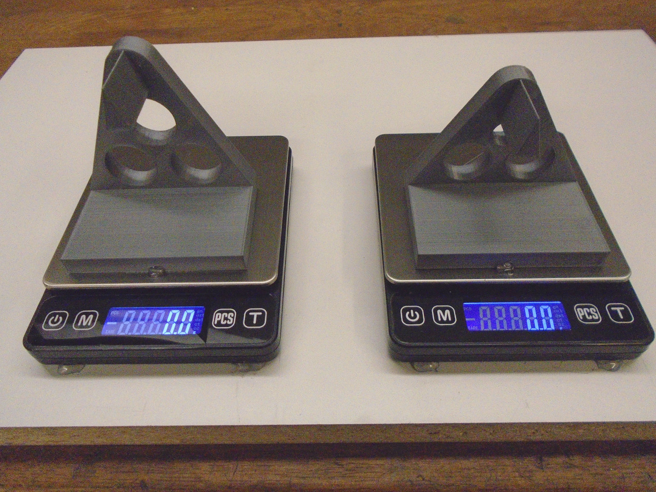
Then, rather than swapping a scale from big to little end, I just
got two of these small scales. They are fairly cheap, have
enough capacity, and are very repeatable in their
measurements. I tacked the brackets to the scale tables with
a little hot glue, and also tacked the scales to a mounting board
such that the distance between the knife edges corresponded to the
distance between the rod bore centers.
After that, it was pretty easy to get weight readings for each
end. I did find that the readings were very sensitive to
slight changes in position of the rod. Very small
displacement left or right would make a difference in the
reading. I addressed this by taking at least ten readings
for each rod, and averaging them.
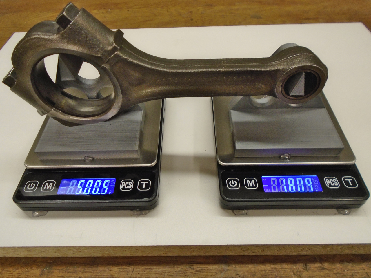
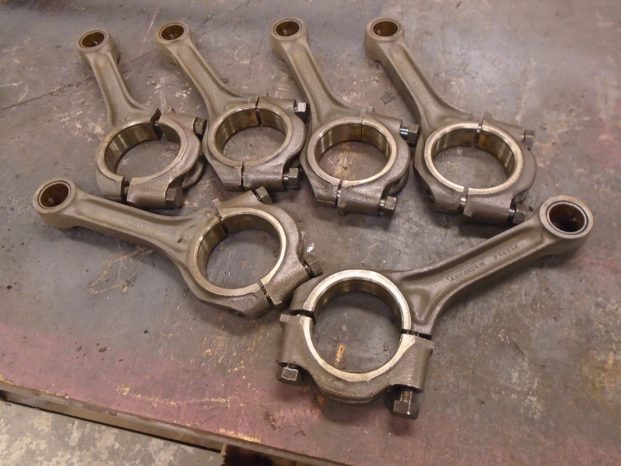
After determining which rod had the lightest big end, I brought
all of the others down to that weight by grinding in various
places. The range was significant, but not huge. The
big ends ranged from around 506 grams to over 512. I got
them down to within one gram.
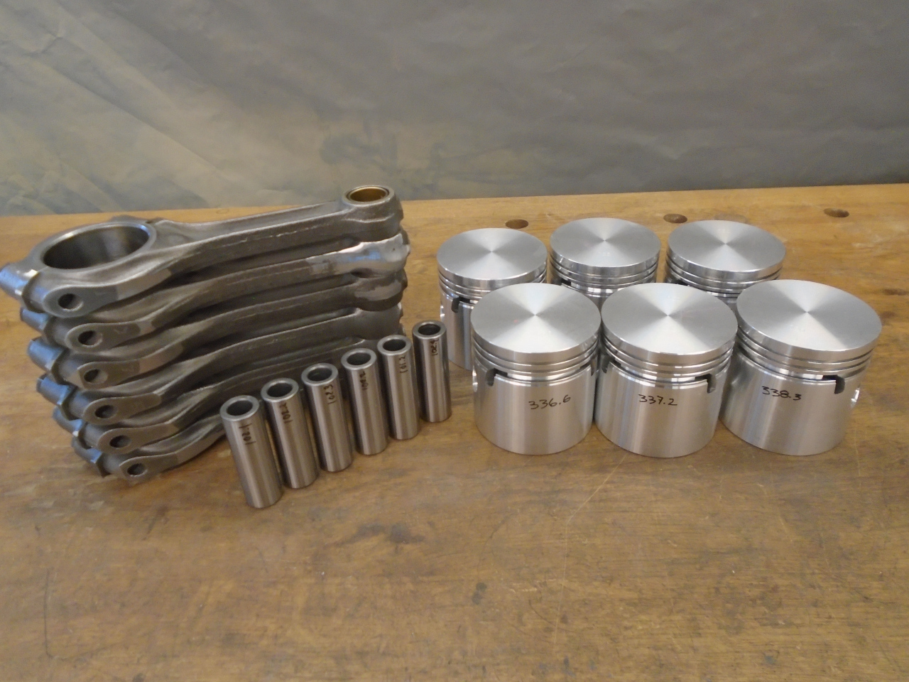
As I was pondering doing the same thing to the small ends, it
dawned on me that what really needed to be balanced on the
reciprocating side was the the combination of everything up
there--the rod little end, the wrist pin, the piston, even the
rings. It didn't really make sense to balance all of those
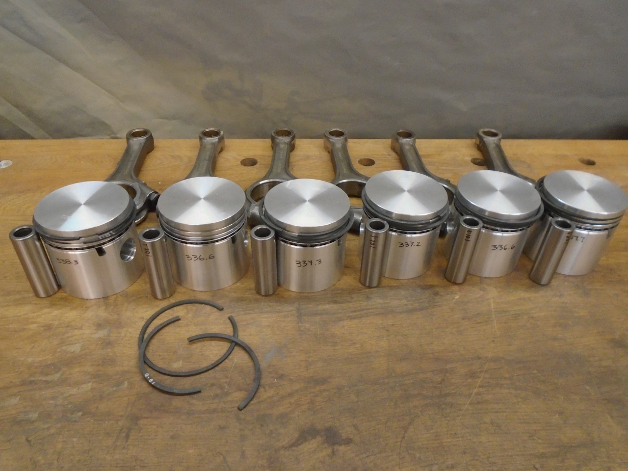
things individually. So I weighed all of those parts.
The pistons varied over about two grams, the pins, a little less
than two. Even the rings varied by nearly half a gram.
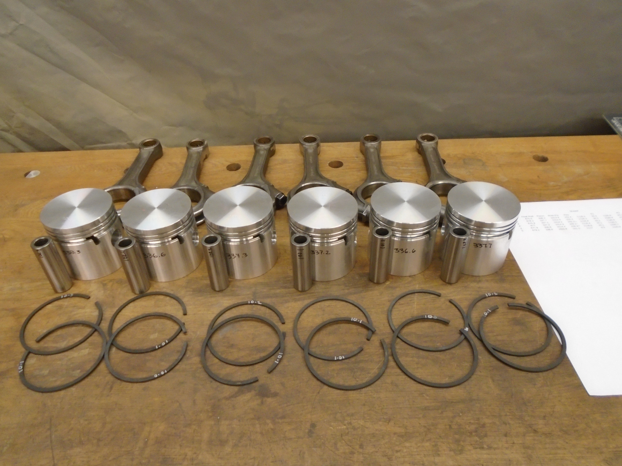
Since I also had the overall weight of each rod, and I knew the
big ends were all about the same, the difference was all in the
little ends. So my plan was to match up the lightest rod
with the heaviest of all the other parts, next lightest rod with
the next heaviest of the other parts, et cetera. This would
narrow the spread, and minimize the amount of grinding
necessary. I did all of this on a spreadsheet before I
assembled anything, so I knew how much weight had to be removed
from each rod/piston set. It was only a few grams at
most. I took the weight off of the rod little ends, since
the heavier steel would require less material removal than for the
aluminum pistons.
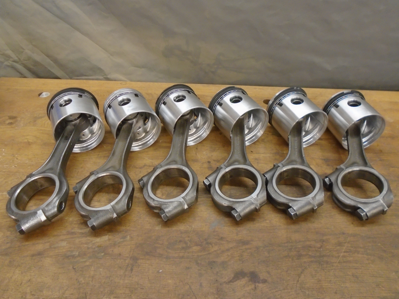
After all of this, I put together the rod/piston assemblies, and
weighed them. I was overjoyed to find that they were all
within a range of a gram or so.
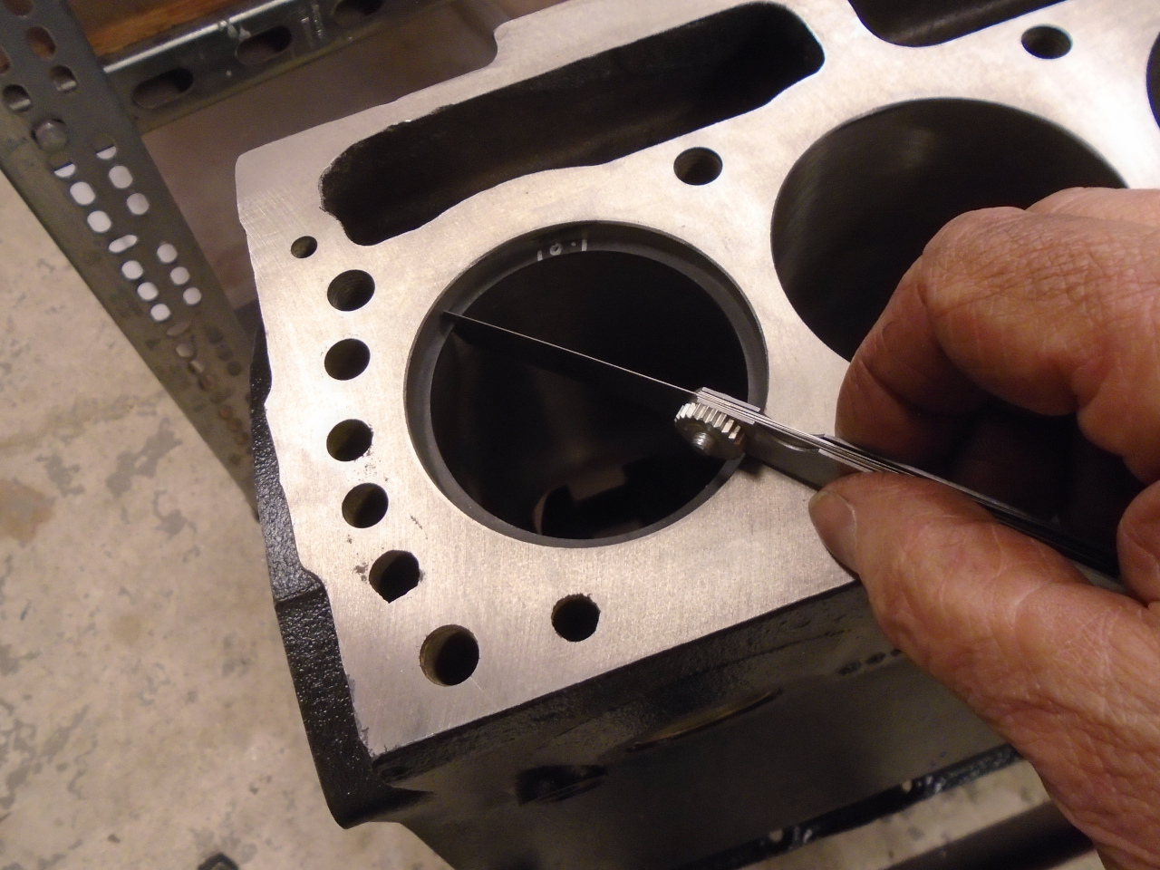
Before installing the rings, I checked the ring gap on a few of
them. They were spot on, so I didn't check the rest.
The assembly process wasn't without a little heartbreak,
though. When installing the rings on the #2 set, I snapped
one of the rings. These are normally only sold in sets, so I
was pretty bummed. I called some vendors. I appealed
to some forums. No one had a single ring to sell me.
Finally, I called Grant Rings, who appears to be the manufacturer
of the rings. As of this writing, I think I have the ring on
the way.
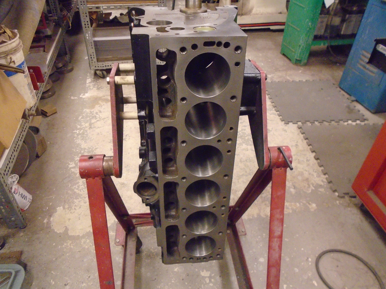
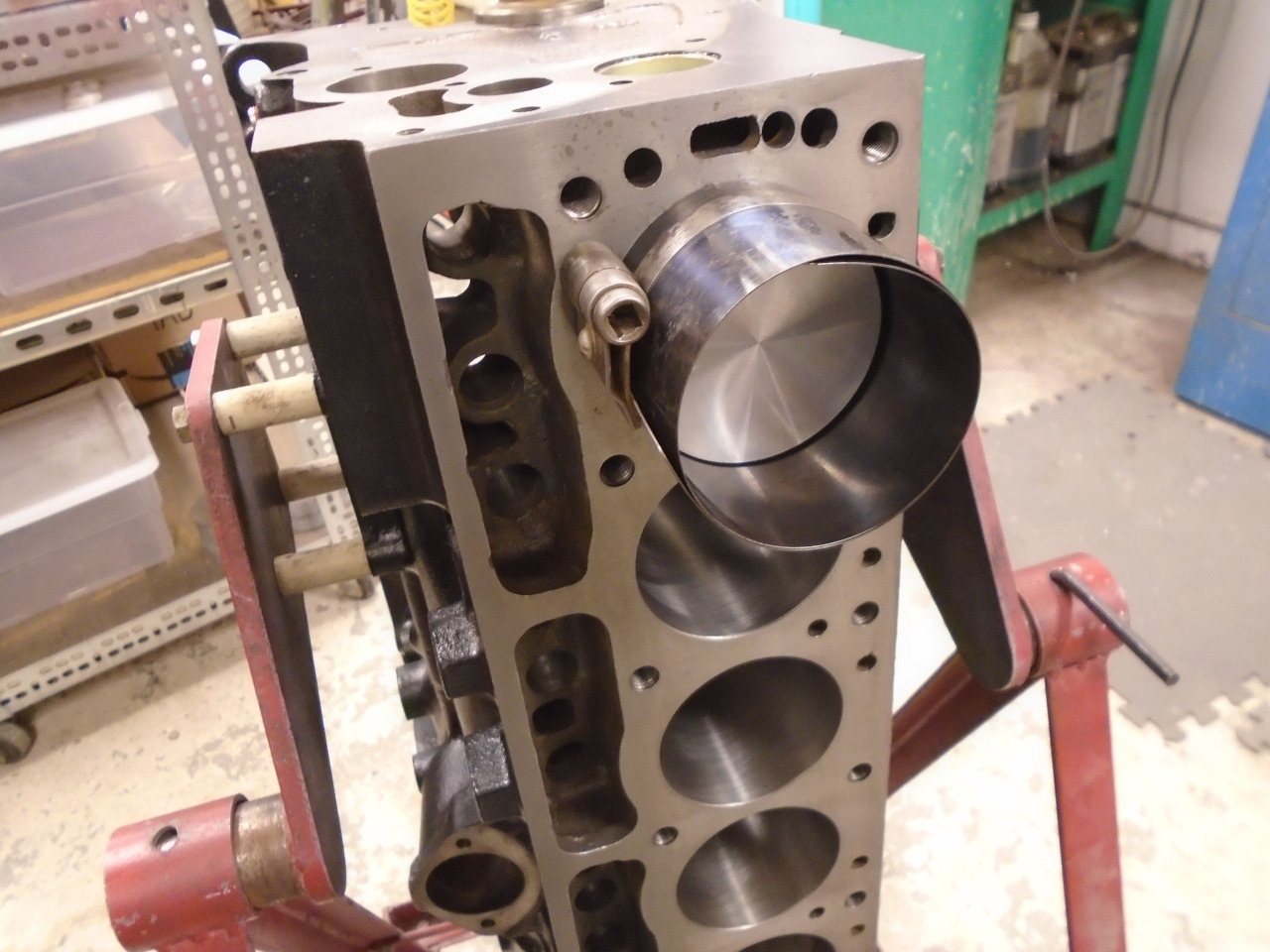
Since I was on a roll, I decided to go ahead and install the five
complete piston sets. I think there are other types, but the
cheap sleeve type ring compressor has always worked well for me.
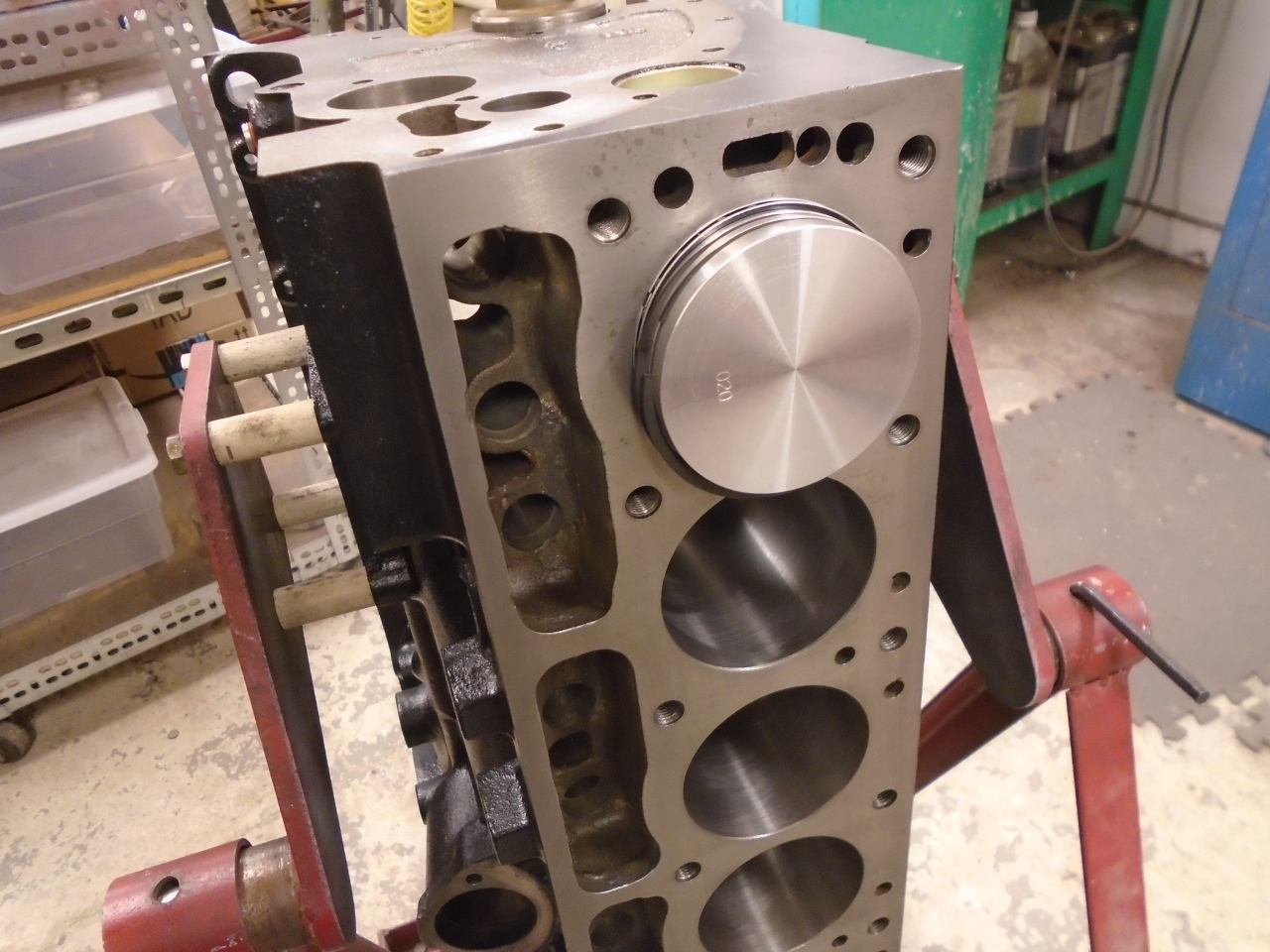
Before buttoning up the first big end to the crank, I
checked the clearance with Plastigage. Like the mains, it
was a little under 0.002". I'd prefer 0.0015", but I can
live with this.
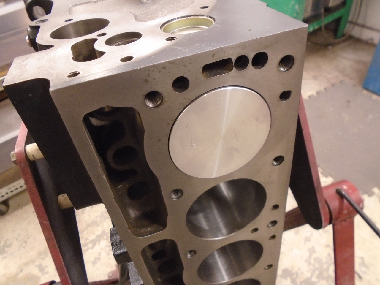
With each piston, rotating the crank got a little harder.
With five installed, I can barely move it by bare hands twisting
the ends of the crank.
So here we are, tapping our foot, waiting for that last ring.
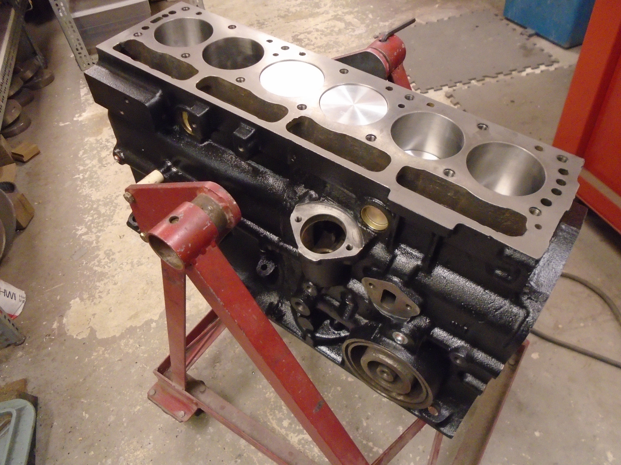
Jobs like this seem like real progress. It was a fair amount
of work, of course, but only around $300 for the pistons and
rings.
Comments to Ed at elhollin1@yahoo.com
To my other GT6
pages.