To my other GT6
pages.
November 24, 2020
Cam Timing
Since the crankshaft determines the positions of the pistons, and
the camshaft determines the positions of the valves, there has to
be a very specific relationship between the crankshaft and the
camshaft rotations to synchronize the four-stroke
choreography. On the GT6 engine, the two shafts are coupled
by a timing chain running on sprockets on each shaft.
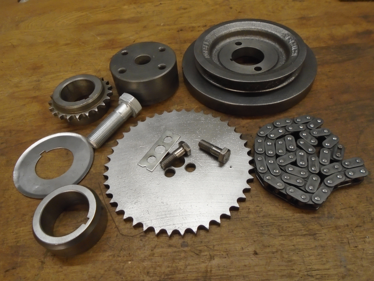
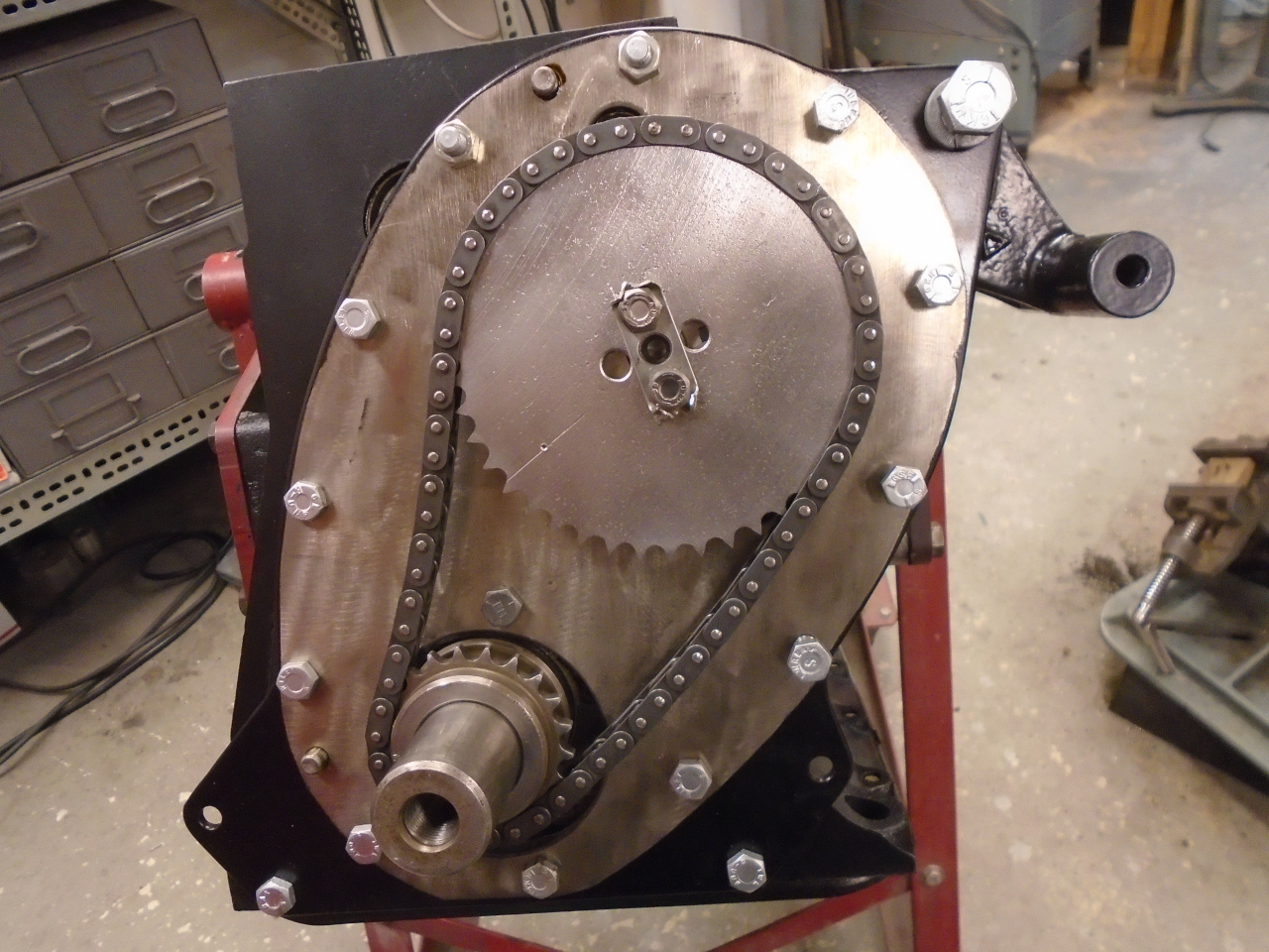
After some cleanup, these are the sprockets, chain, and some other
nearby parts. The sprockets and chain were replaced in my
earlier rebuild, so are close to 30 years old, but still young in
terms of miles. They show little or no sign of wear, so I'll
re-use them.
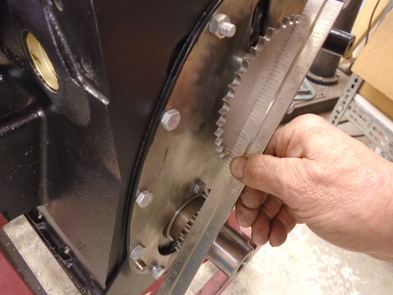
For long chain life, the sprockets need to be aligned to be
co-planar. This can be adjusted by using shims under the
crankshaft sprocket, but I didn't need any.
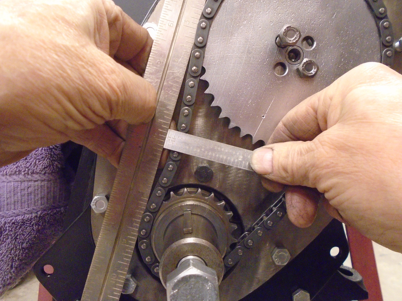
Chain stretch is measured by the gap between the slack side of the
chain, and a straight edge. The factory workshop manual
allows 0.4", but I had less than half that.
So, to set the cam timing, we need two datum points: For the
crankshaft, it is Top Dead Center (TDC) of the #1 (front) piston,
and for the camshaft, the position of the #1 or #6 cam
lobes. Since pistons #1 and #6 share the same TDC, it's the
cam, which rotates half a turn for each full turn of the crank,
that determines which one is on the compression/power or the
exhaust/intake stroke.
The stock GT6 cam and many of the popular replacements are
"symmetrical" cams. This means that for each cylinder, the
max lift points of the intake and exhaust valves are set to
"straddle" TDC for that cylinder. That is, the number of
crank degrees between max exhaust lift and TDC is the same as the
number of degrees between TDC and max intake lift. So a
common method for symmetrical cams is to set the cam so that the
#1 (or #6) intake and exhaust lifters are at equal lift (intake
rising, and exhaust falling), set the crank at TDC, and install
the chain to hold that relationship.
However, my new BP270 cam from BPNW is not symmetric. Max
inlet and exhaust lift points are not to be centered around TDC,
and the opening and closing ramps are not the same, so another
method of timing is necessary. It is actually simpler.
For this cam, the data sheet instructs to set the cam such that
the #1 intake lifter is at max lift, set the crank to 112 degrees
After TDC, and install the chain.
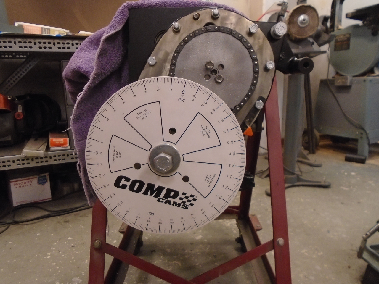
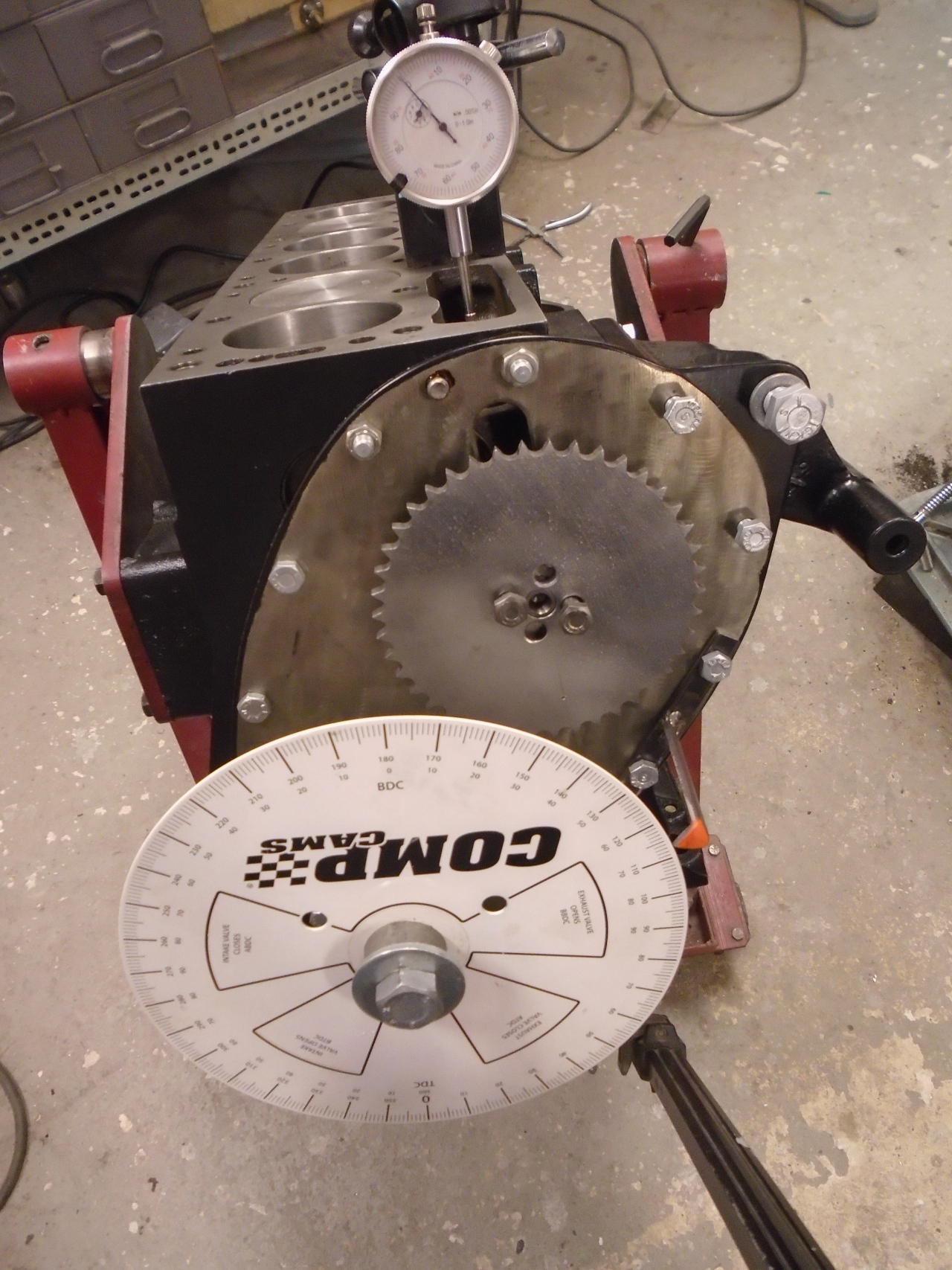
Obviously, some way of measuring degrees of rotation on the crank
is necessary. This is a generic degree wheel, with a simple
pointer bolted to the block. The wheel is set at an
arbitrary position to start.
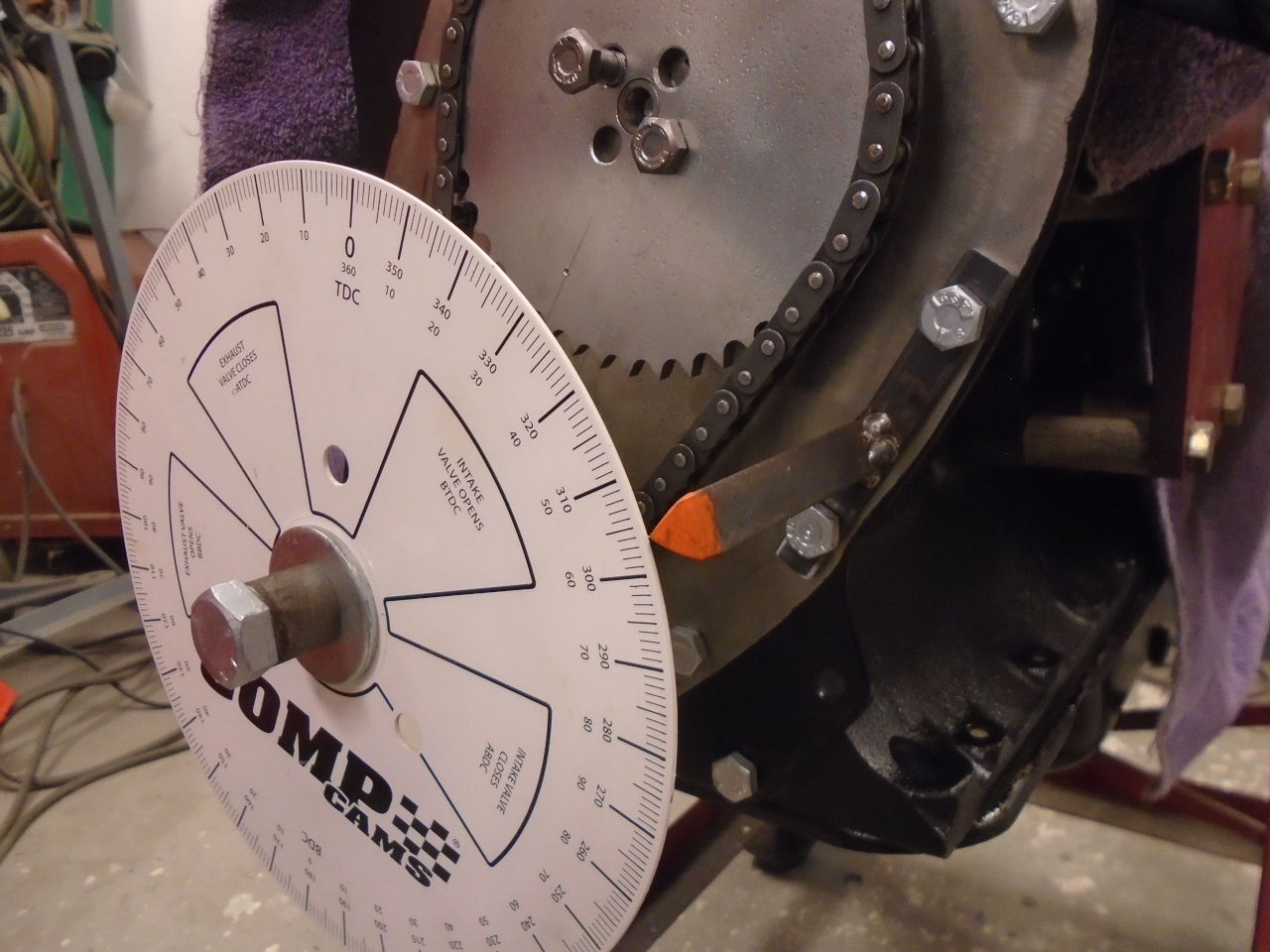
A dial indicator is used to find TDC. Since motion of the
piston is very insensitive to crank rotation near TDC, one way to
do this accurately is to pick a piston position around 1/2" below
TDC on the rising side, and note the indicator reading and the
degree wheel reading. Rotate the crank clockwise (facing the
front of the engine), past TDC, until the indicator reading is the
same as before, but on the falling side, and again note the degree
wheel reading. TDC will be halfway between the two degree
wheel readings. Set the crank there, loosen the degree
wheel, set it at 0 degrees (TDC), and tighten it. The pic
shows doing this with the chain installed, but it normally would
be done without the chain.
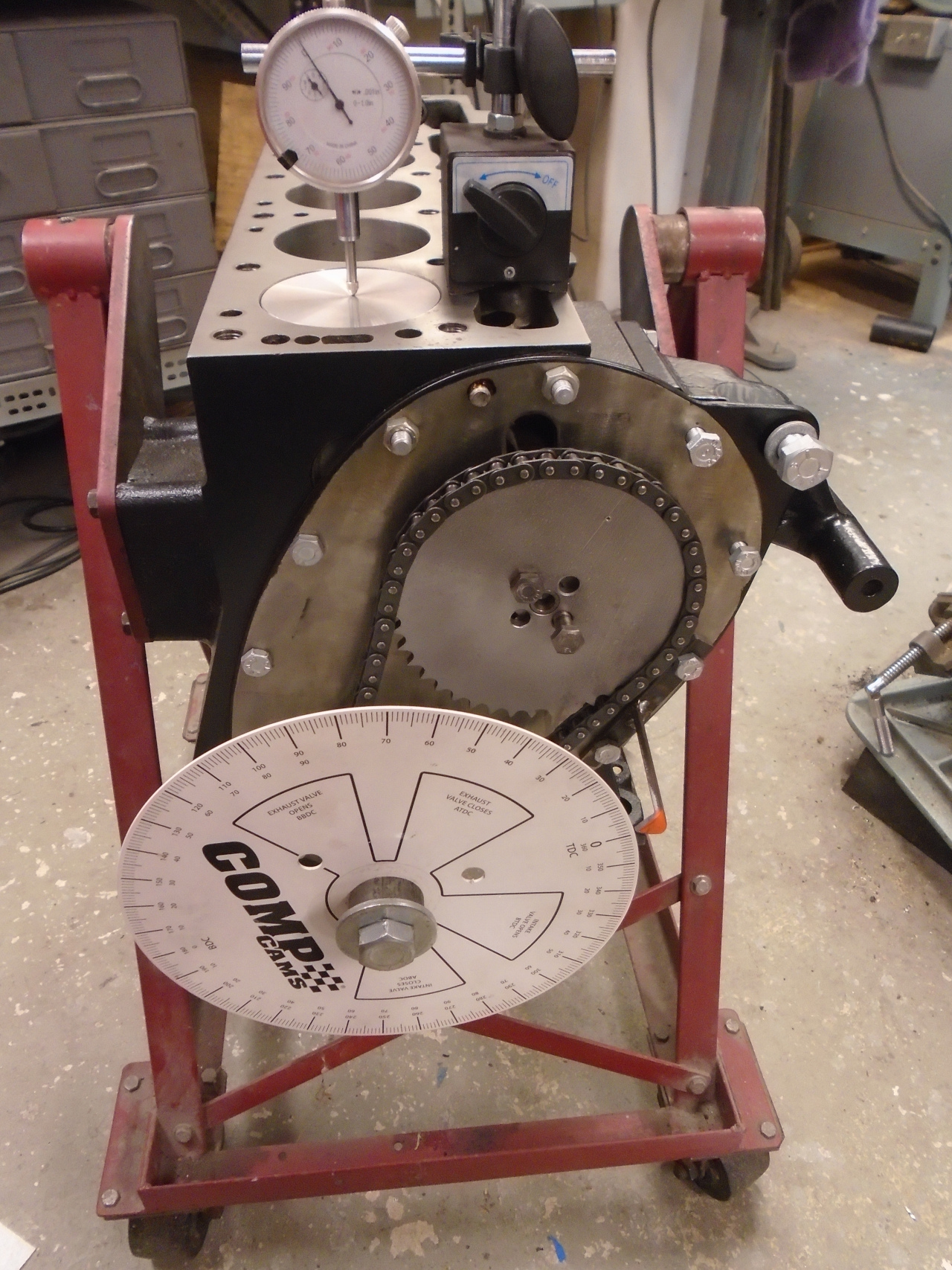
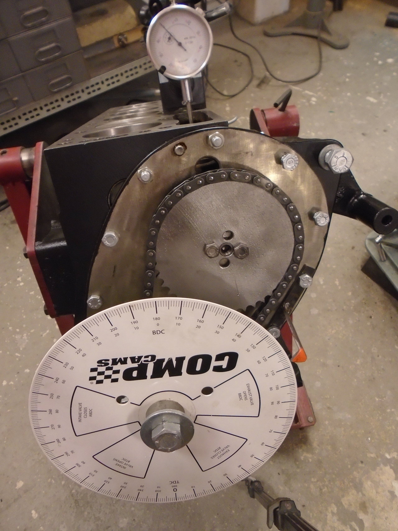
To measure cam lobe position, I made this little slug to fit in
the back of one of the lifters.
With the lifter installed for the #1 intake valve, the dial
indicator was moved to measure lobe lift, and the cam rotated to
maximum lift.
The crank was then rotated clockwise to 112 degrees ATDC, and the
chain was installed.
A word about how close you can get to the specified setting:
The cam sprocket has 42 teeth, which puts them about 8.6 degrees
apart. So the error from some intended setting could be as
much as 4.3 degrees. To the crank, which turns twice as
fast, this error would be 8.6 degrees. On the positive side,
Triumph engineers included two pairs of mounting holes on the cam
sprocket 90 degrees apart. This 90 degres represents 10.5
teeth on the sprocket, so that by moving to the alternate pair of
mounting holes, the sprocket effectively advances 1/2 a tooth, or
4.3 degrees. This has the effect of cutting the potential
error in half, which brings us back to 4.3 degrees at the
crank. Fortunately, small errors in cam timing don't usually
make a huge difference in performance. Even so, some tuners
will intentionally set cam timing a few degrees off either way,
depending on what they are trying to optimize. The error in
my installation was pretty small--maybe a degree or so advanced.
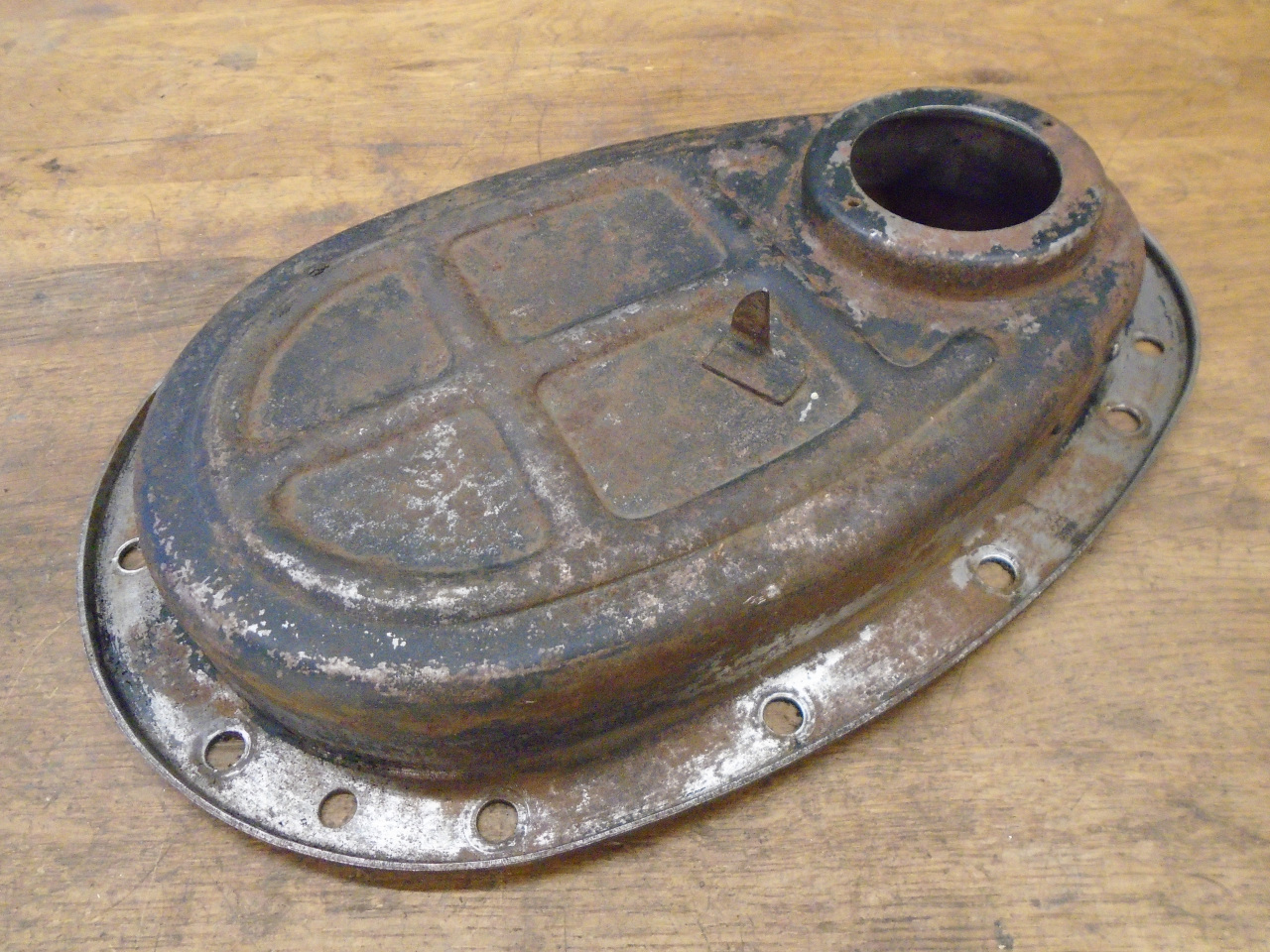
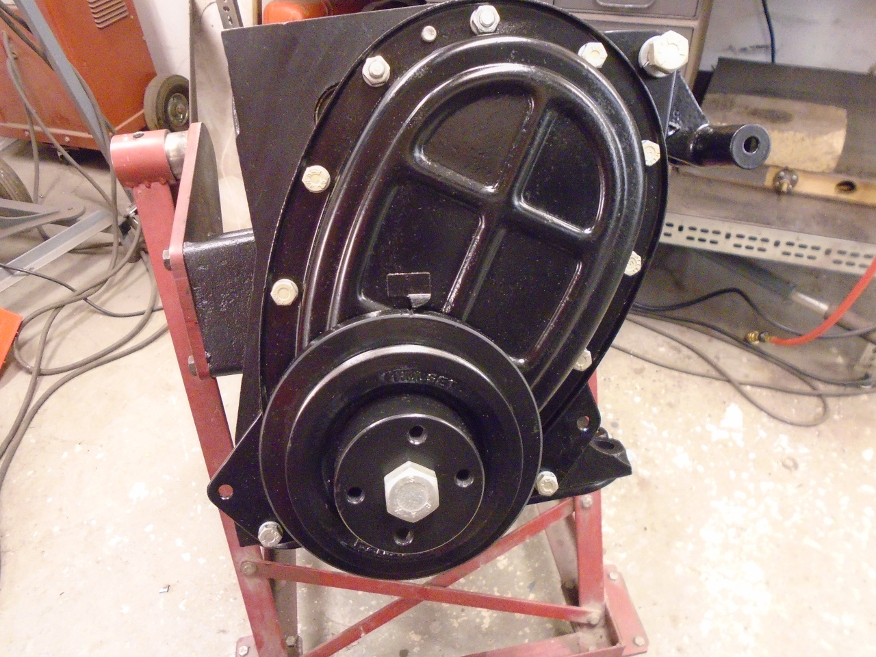
So, with all the brain work wrapped up, it was nice to turn to
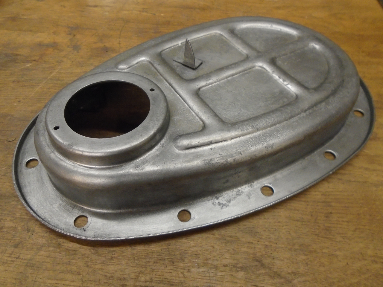
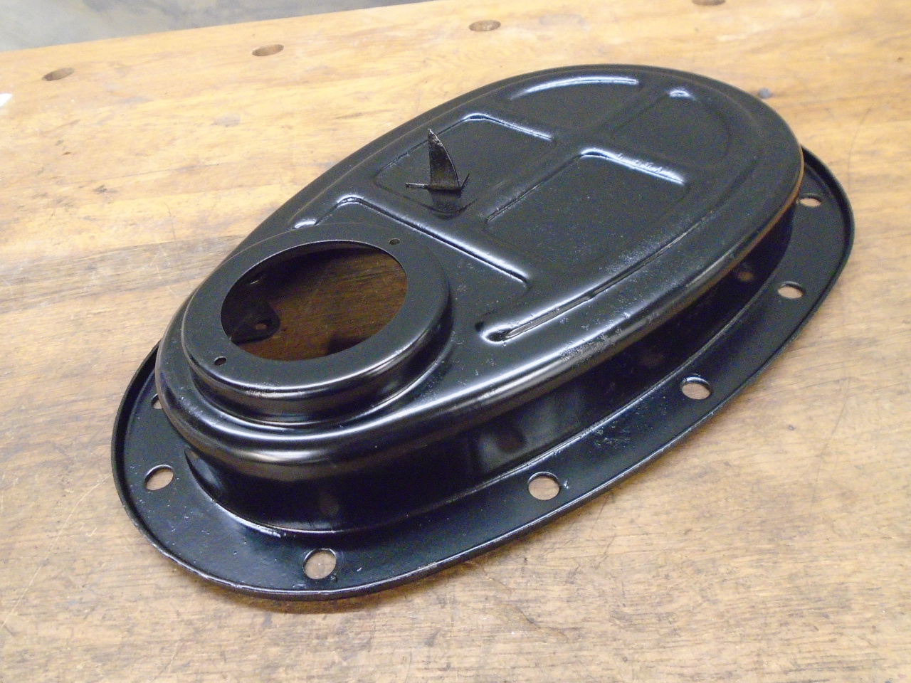
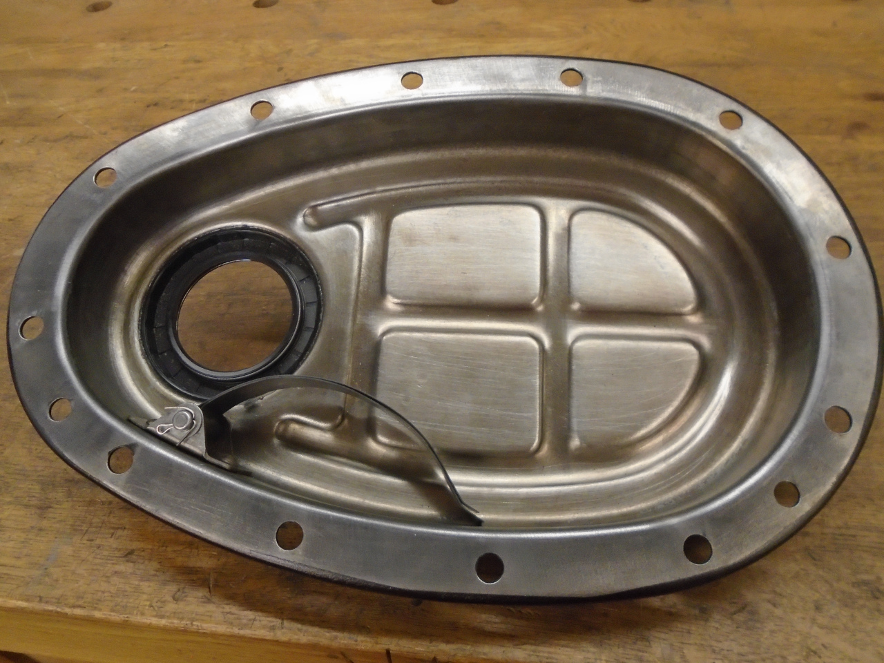
something less taxing. The timing cover was pretty rusty,
with some remnants of paint, but it cleaned up and powder coated
pretty well.
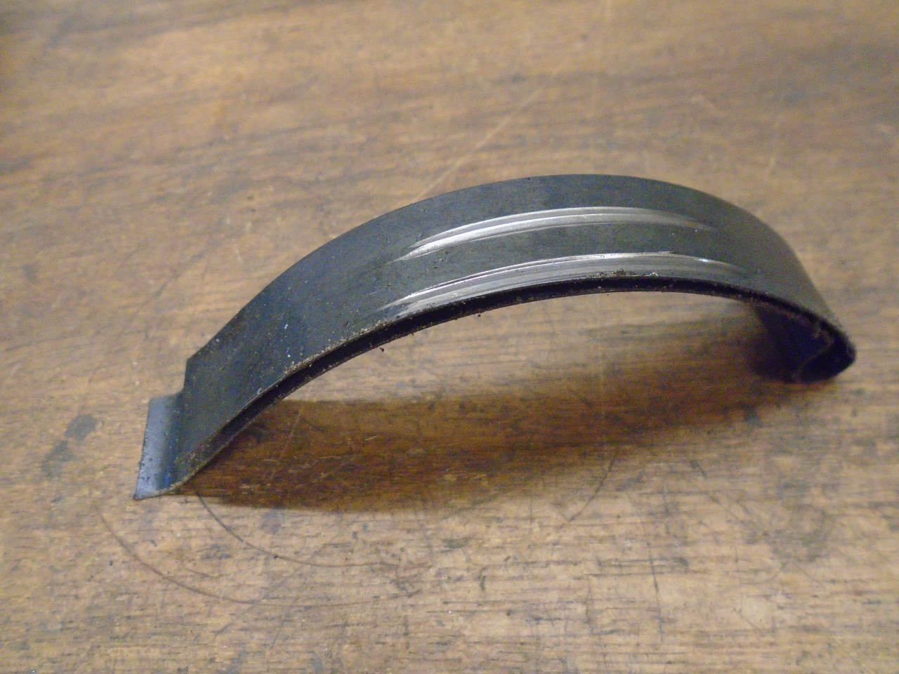
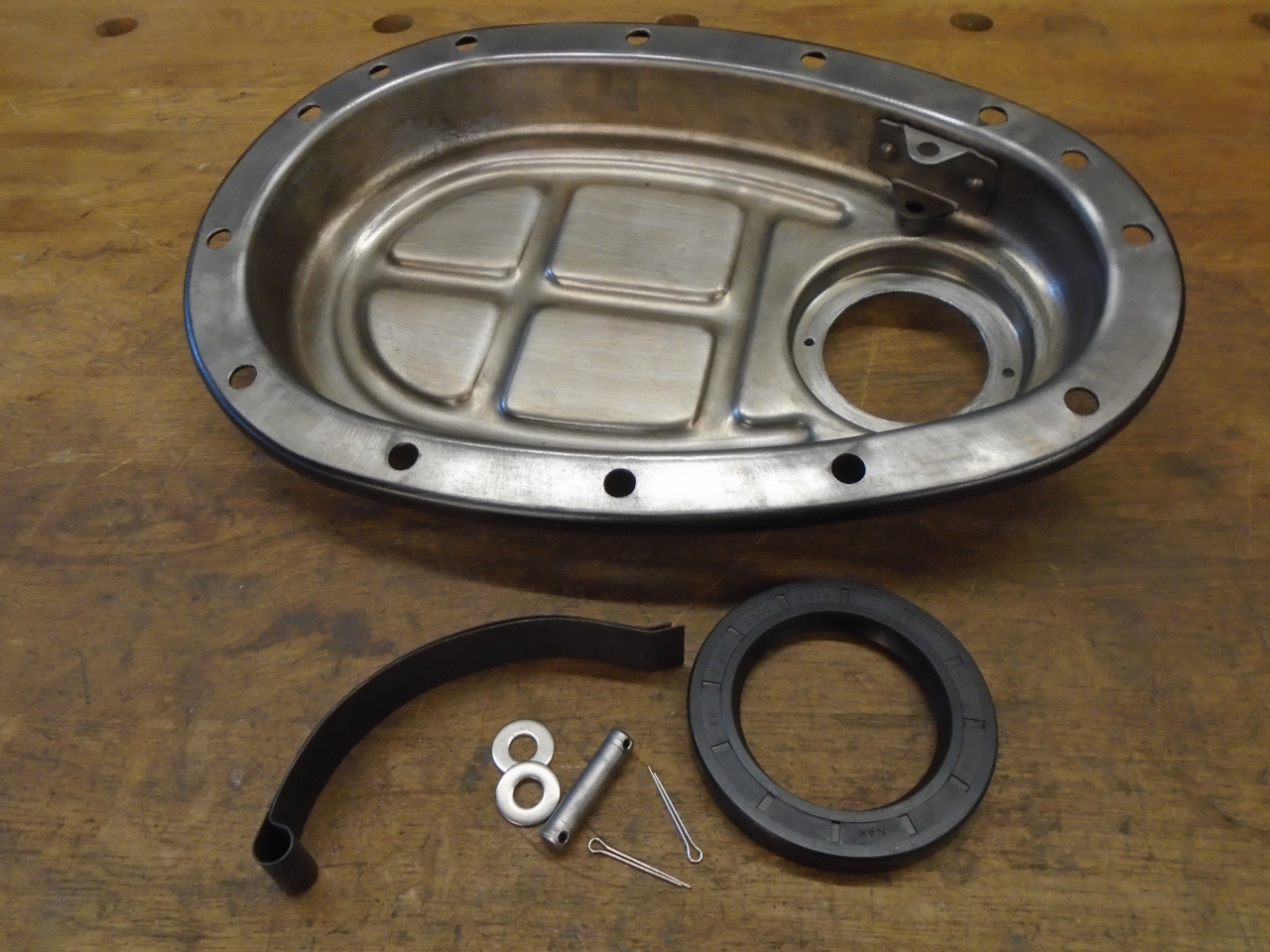
The tensioner was well scored, so I installed a new one, along
with a new oil seal.
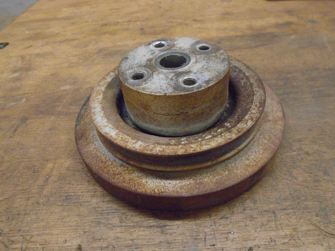
While thinking about stuff at the front of the engine, I dug out
the harmonic damper. Though appropriately crusty on the
outside, the damper appeared to be intact, with no detectable play
between the outer ring and the hub. I'm not a subscriber to
the notion that some deterioration of the exposed rubber is an
indication of damper failure. That rubber on the surface is
exposed to a lot of things bad for rubber--mainly oxygen, ozone,
moisture and various noxious hydrocarbons. The rubber inside the
damper that actually dos the work is not exposed to these
things.

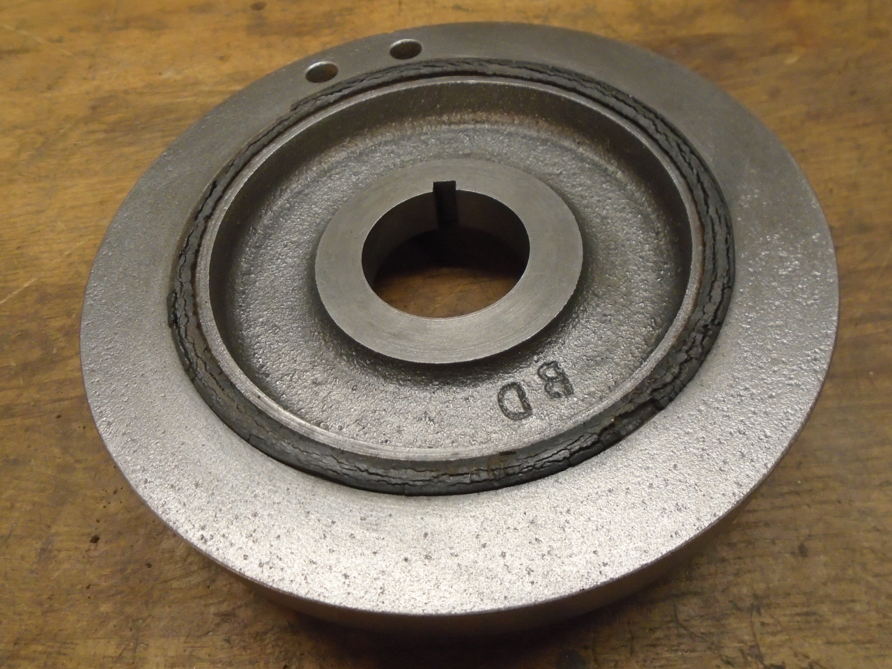
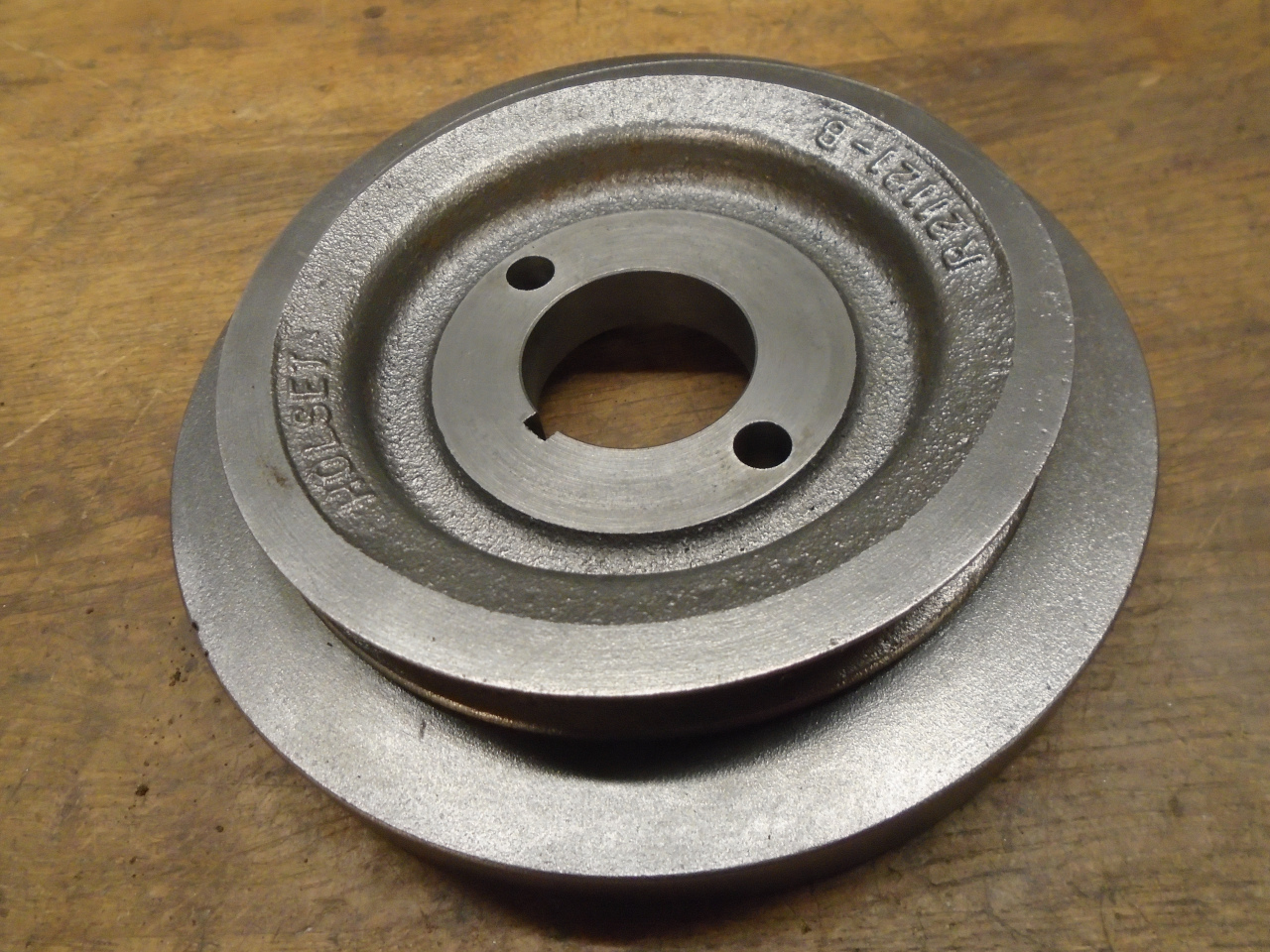
Beyond this, my skeptical nature frets about some aftermarket
parts or "rebuilding" outfits. A harmonic damper is part of
a tuned system, and though deceptively simple, there is a lot of
science inside. So, barring any evidence of slipping or
other damage or degradation, I don't have reservations using ths
original damper.
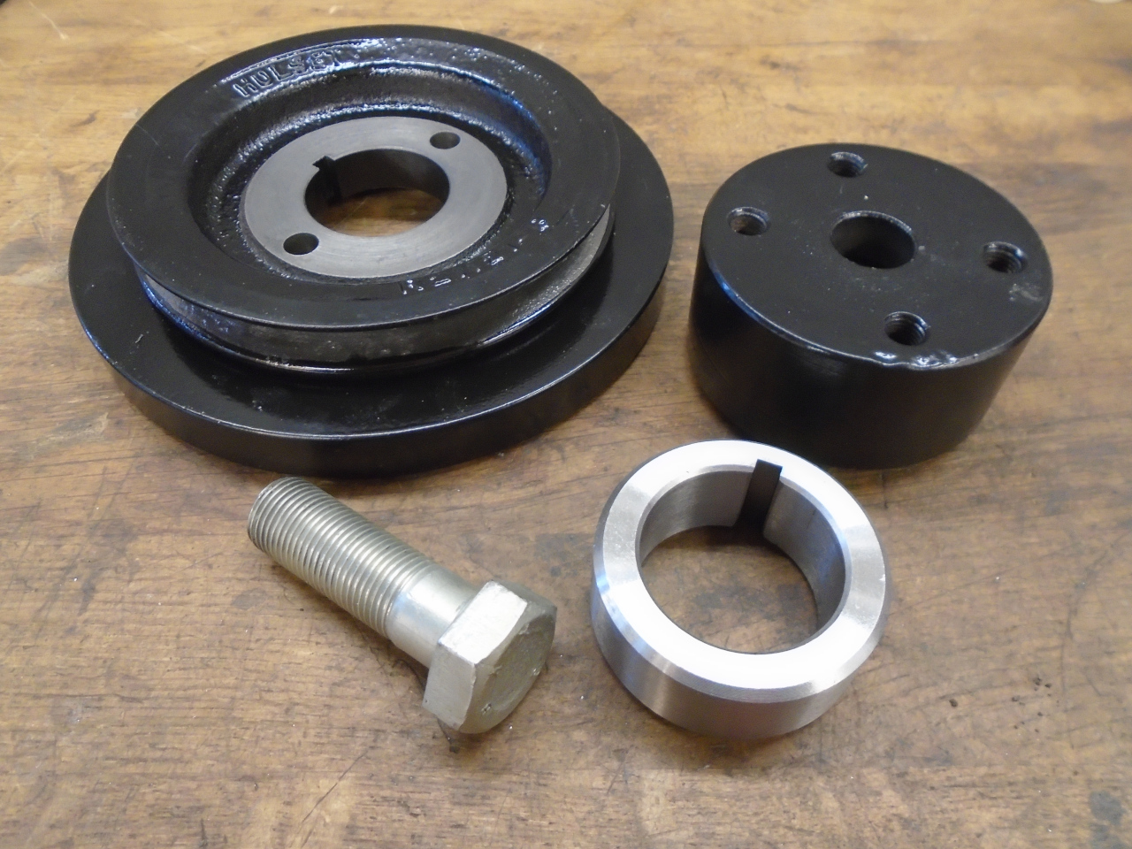
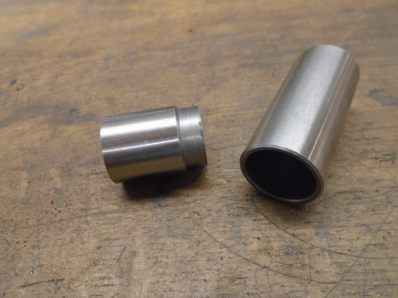
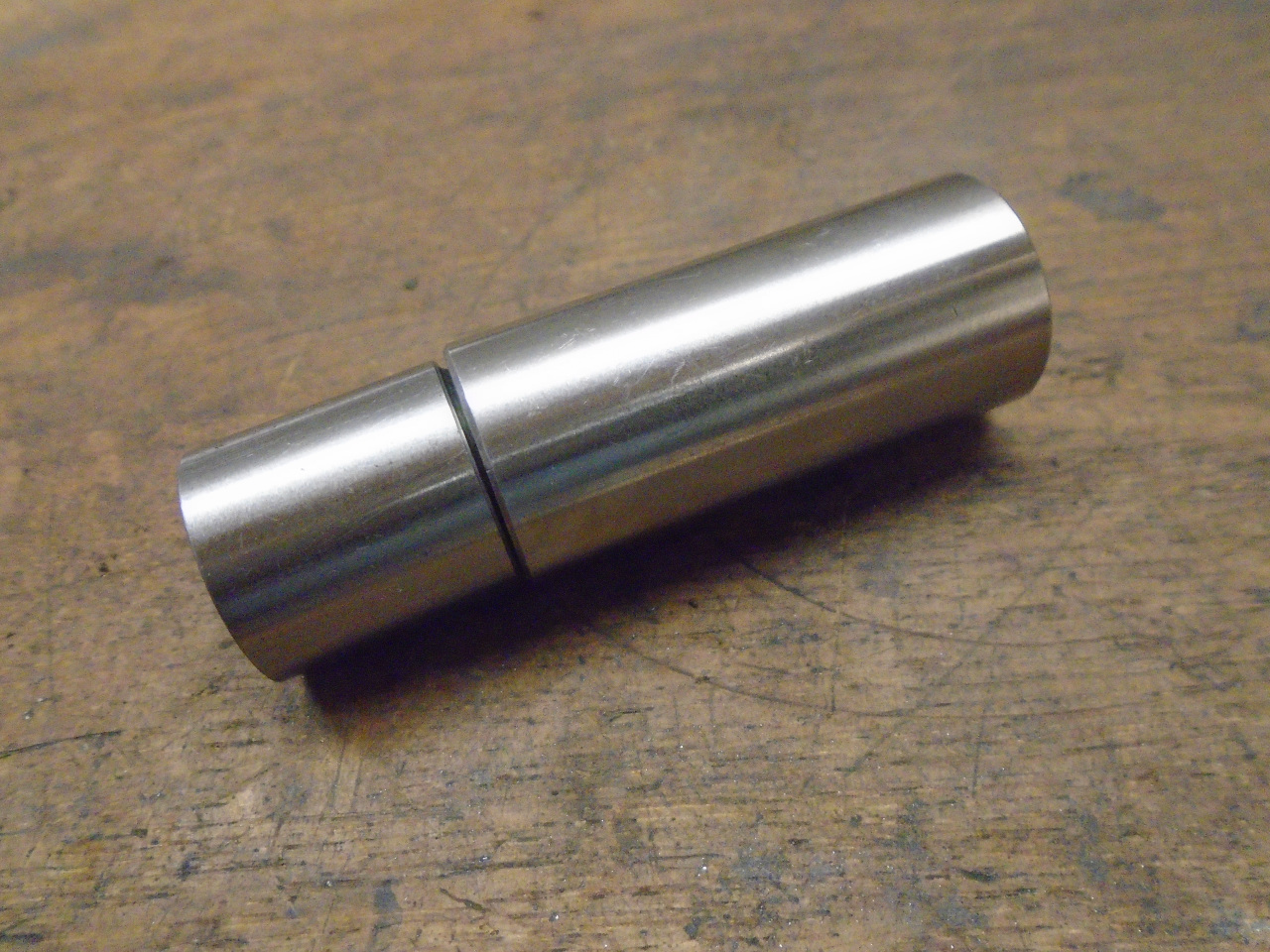
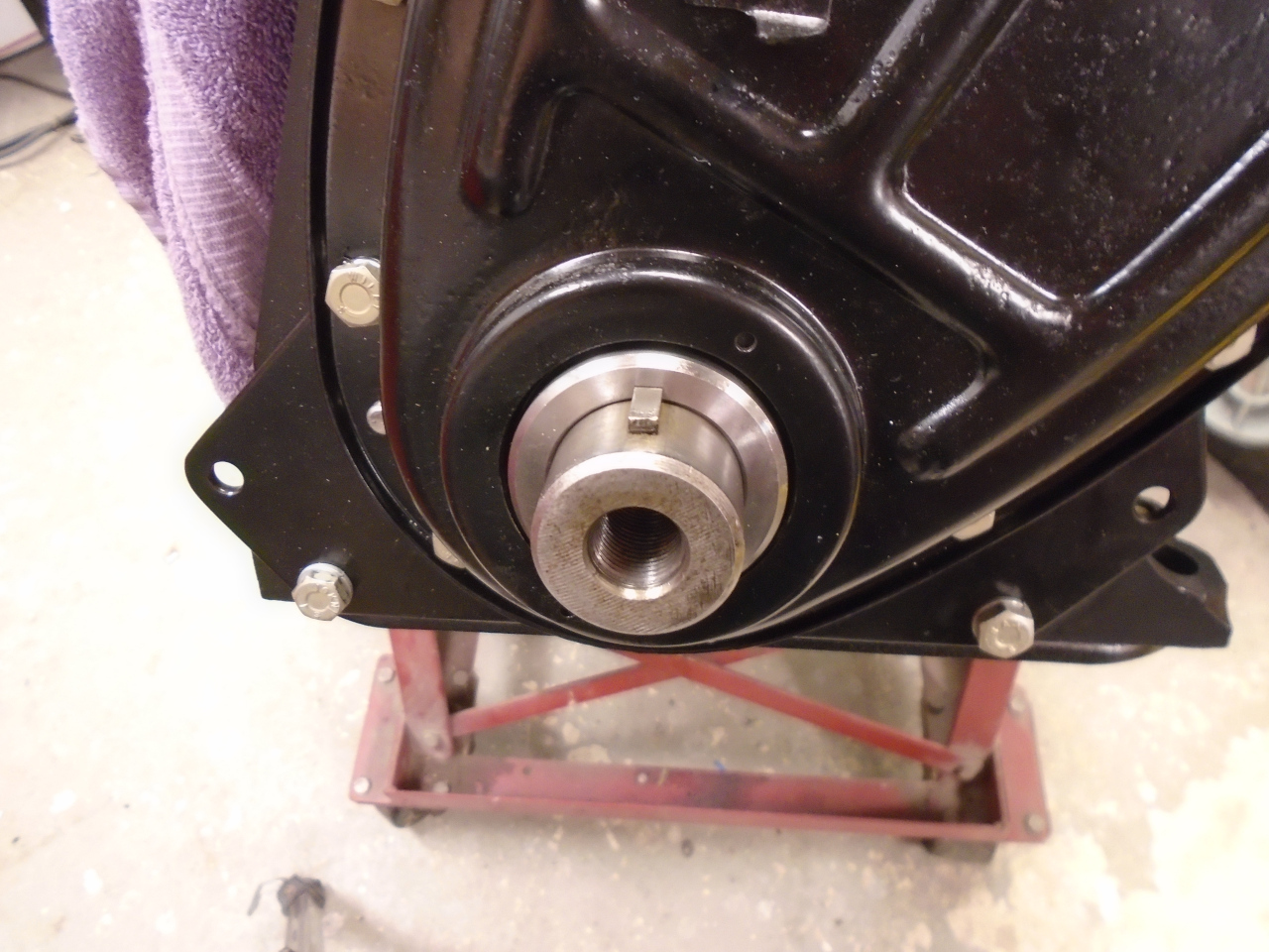
The front seal sleeve showed a slight groove where the seal
rubbed. Since the sleeve is almost symmetrical, I just
flipped it over, which gave a fresh surface for the new
seal. I did enlarge the chamfer on the leading edge to match
the one on the other end, to help it slide into the seal.
All buttoned up. I'd checked it before, but note that with
the engine at TDC, the indication on the damper is correct.
I'll probably run an electric radiator fan, so that fan mounting
hub may go away.
This was one of the more expensive parts of the project--about
$400 for the cam and lifters, but was good for a few enjoyable
afternoons in the shop.
Comments to Ed at elhollin1@yahoo.com
To my other GT6
pages.