As mentioned previously in this chronicle, I believe that the electrical
system designs of LBCs of this era were marginal at best. The
electrics contribute more than their fair share of problems on these
cars, and I'm not alone in this belief. Aftermarket products are
available to improve and upgrade the electrical systems. Some of
these include a new harness and a power center that includes an expanded
number of relays and fuses. I looked pretty closely at a couple
of these systems, and they seem to be well thought out and
designed. They are really just a direct replacement of the
original system though, and don't necessarily easily accommodate custom
modifications. For example, I added seat heaters and an electric
radiator fan, and extensively redesigned the dashboard. Also, the
aftermarket offerings fail to fully address one of the central problems
of the OE systems: the grounds.
Historically, most cars have used the body of the car as the return
conductor for most circuits. This works fine when the car is new,
but the ground connections can be susceptible to corrosion, often
exacerbated by moisture.
For these reasons, I resolved to design an electrical system from
scratch that would address these problems to my satisfaction. The
heart of the system is what I call the "Power Module",
that holds all of the relays, flashers, and fuses. The Power
Module connects to devices throughout the car mainly through two cables,
one to areas forward of the firewall, and one to the rear of the
car. The Power Module also connects to the dashboard.
For no particular reason. I started the wiring with the rear
cable. It connects all of the lights at the rear of the car, the
fuel tank sender, the dome light and rear demister, the hand brake,
reverse, and brake switches, and the door switches for the dome
light. The cable splits under the dash, with one part going to the
Power Module and the other going to the center dash.
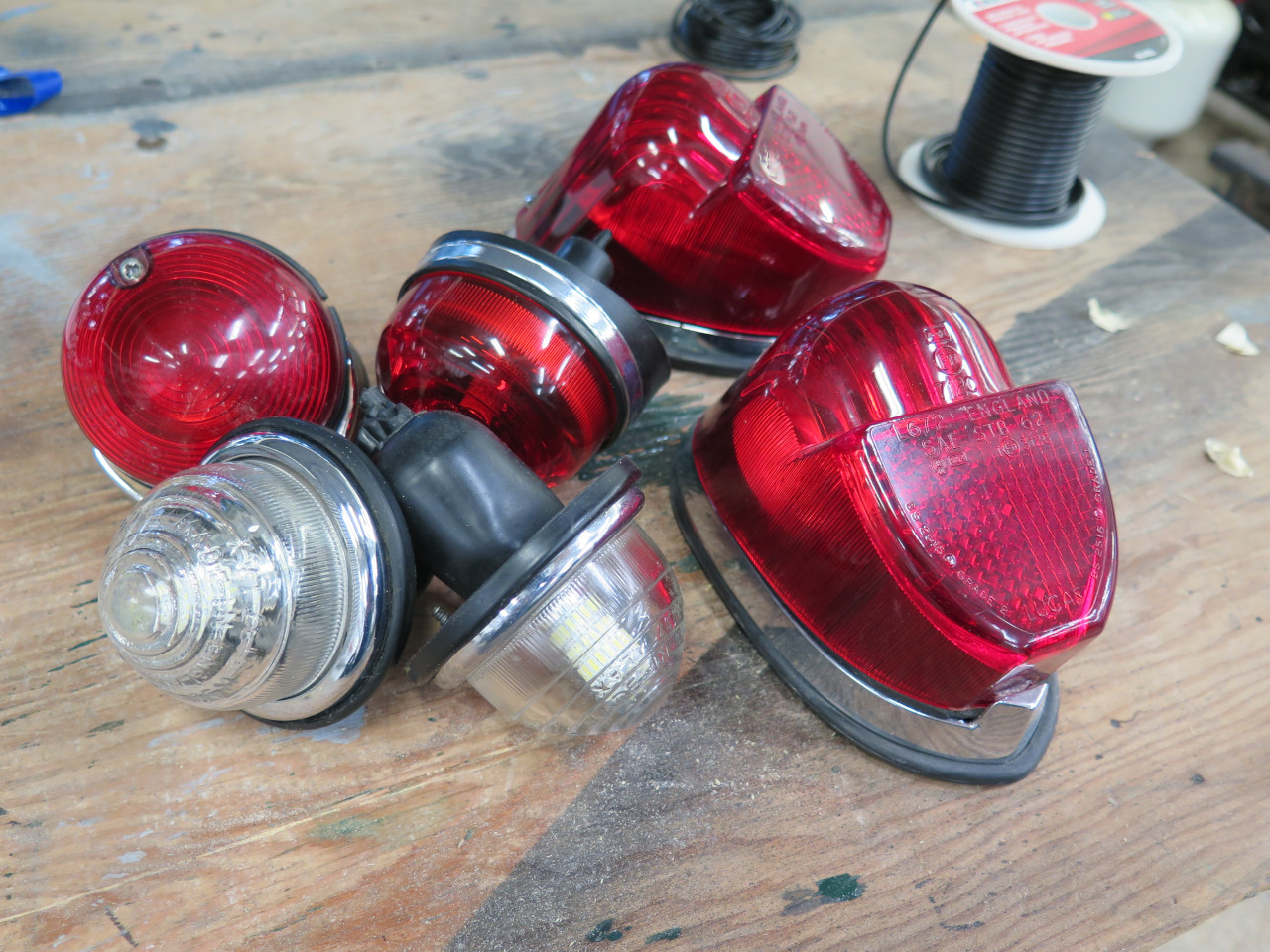
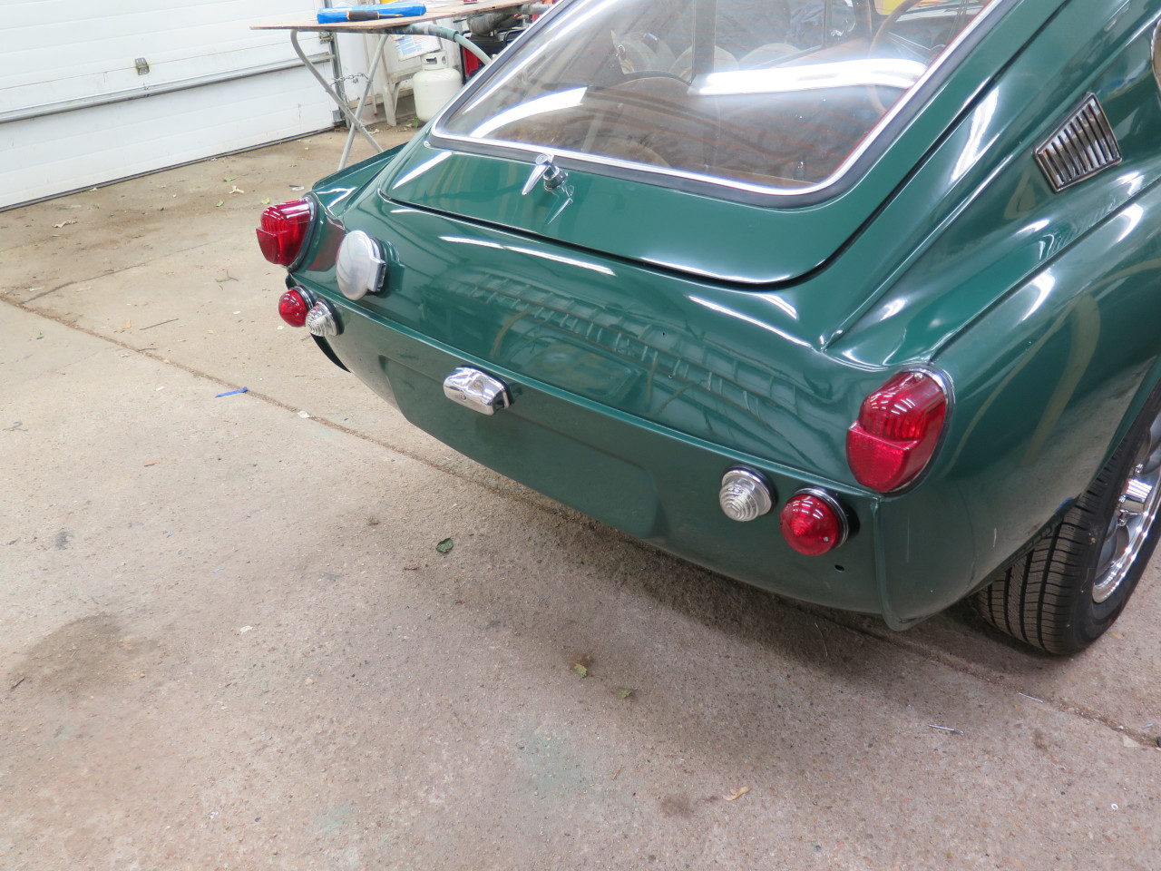
Backup lights were first. I added pigtail wires and gathered up the hardware.
I don't have a pic, but I put a bead of strip caulk between the socket assembly and the car body.
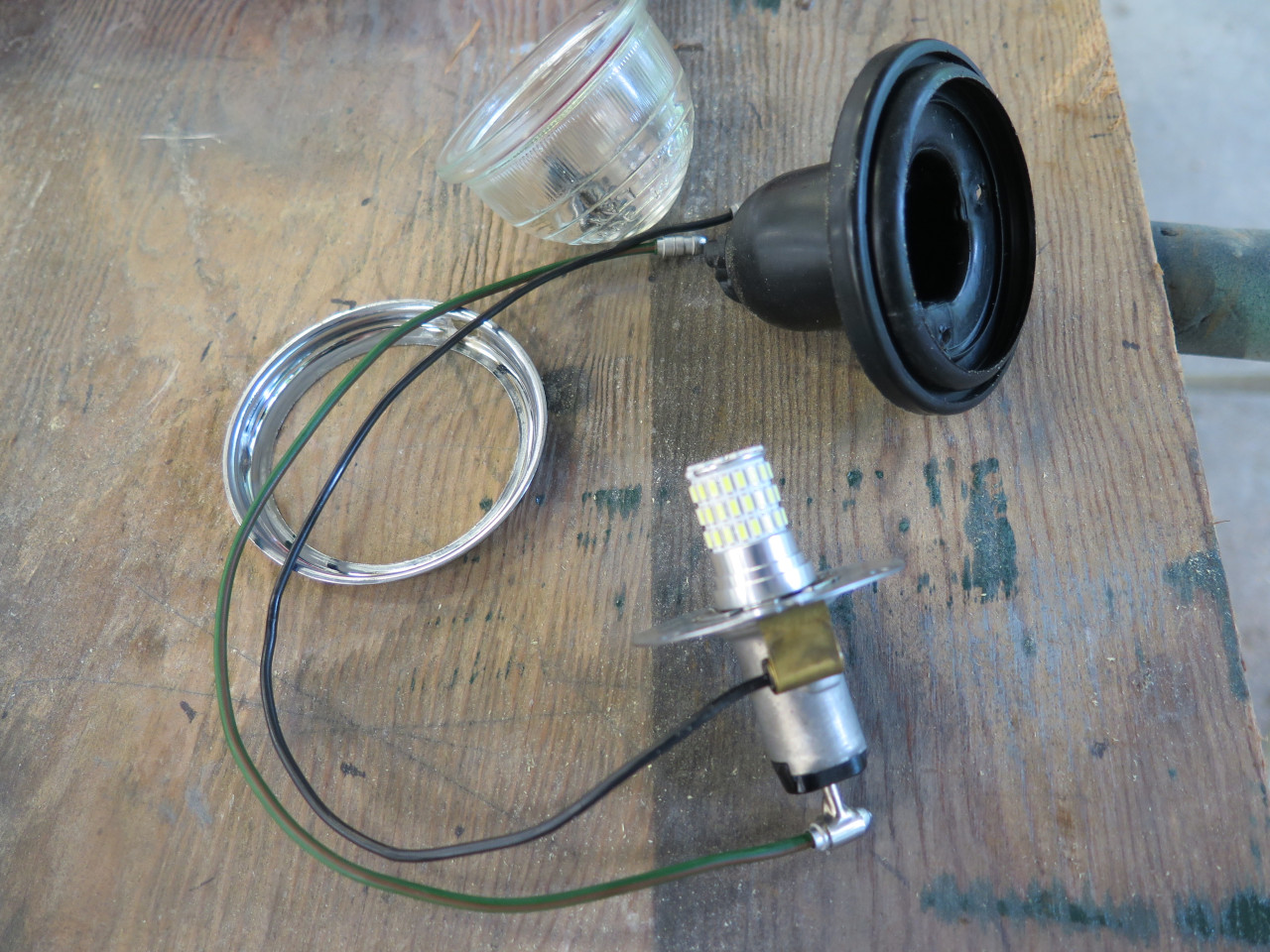
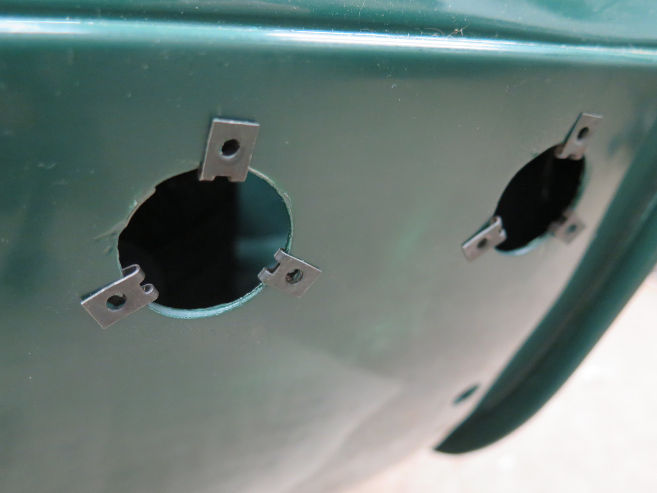
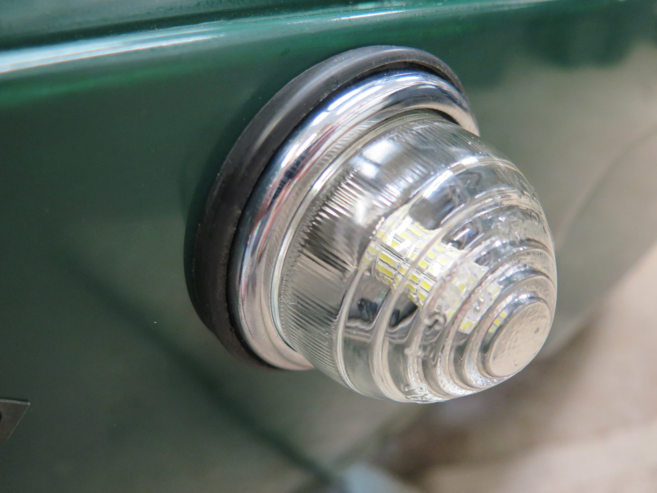
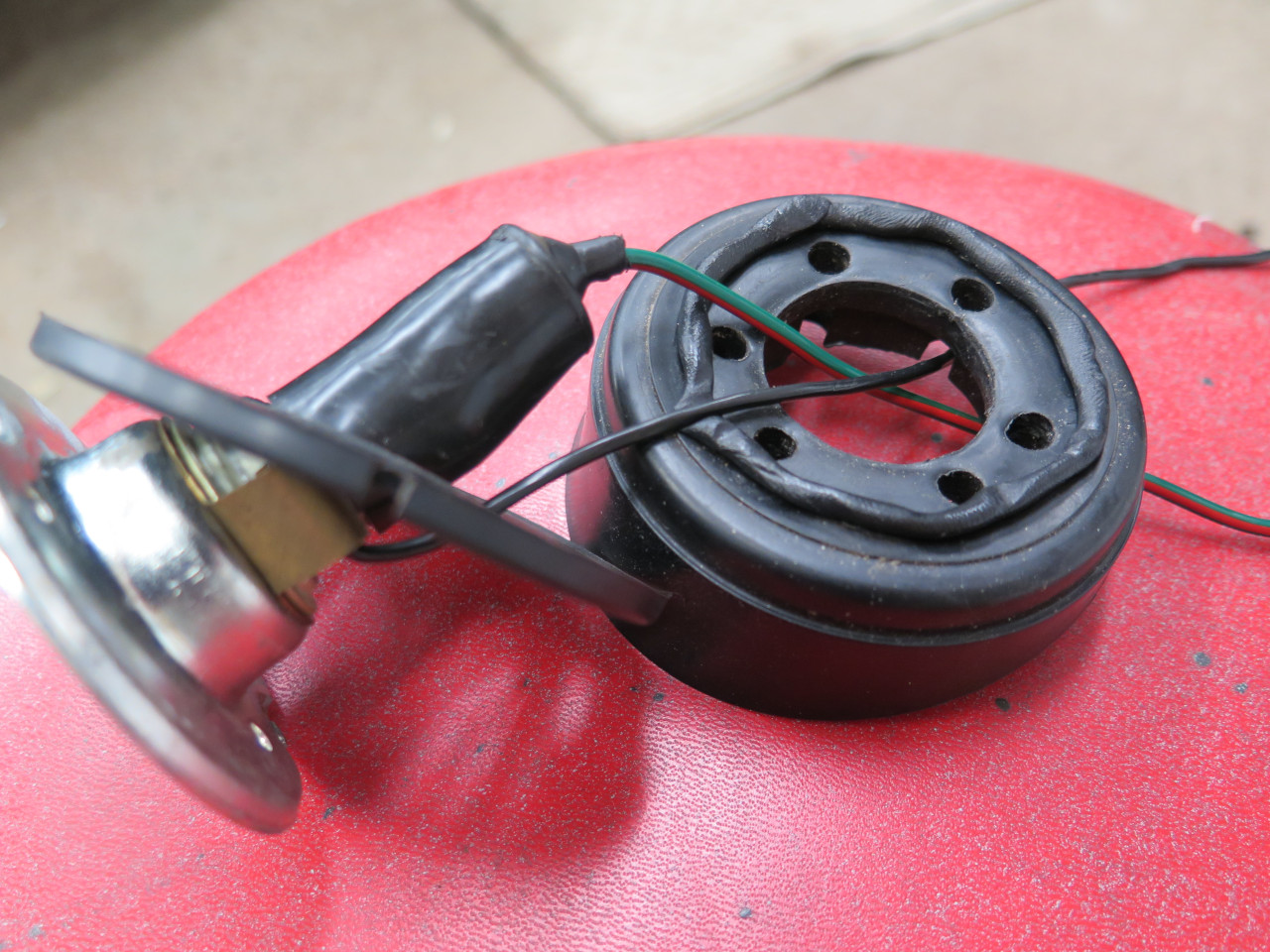
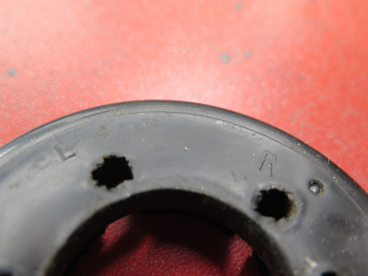
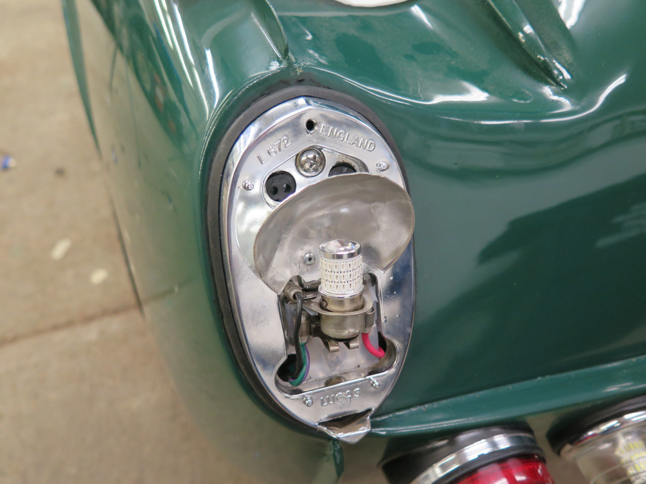
Turn signals next. Unlike the backup lights, the turn signals are
mounted on a specially shaped rubber spacer that insures that the lights
are aimed directly to the rear. The spacers have to be oriented
correctly to accommodate the compound curve of the body. The "L"
and "R" markings indicate which mounting holes to use. Some strip
caulk on the car body and on the spacer hopefully keeps water out.
License plate light got some pigtails and strip caulk.
So far, so good.
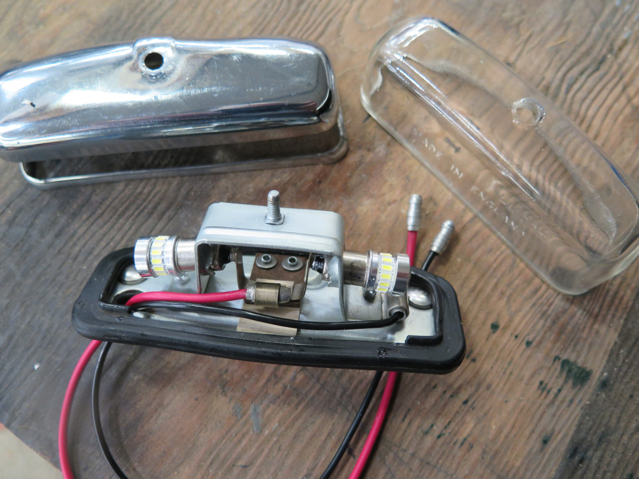
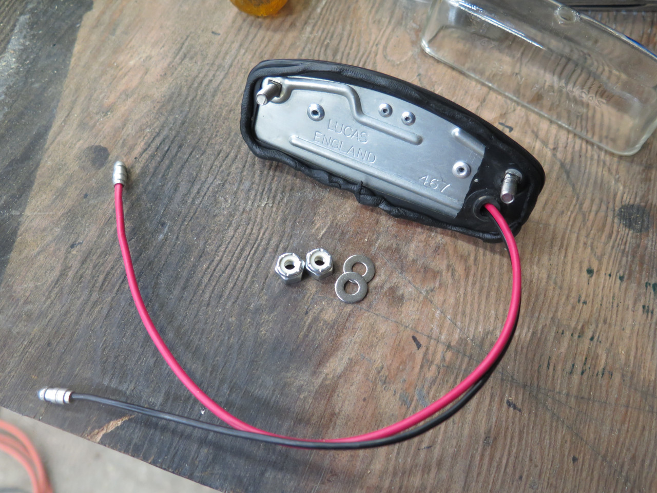
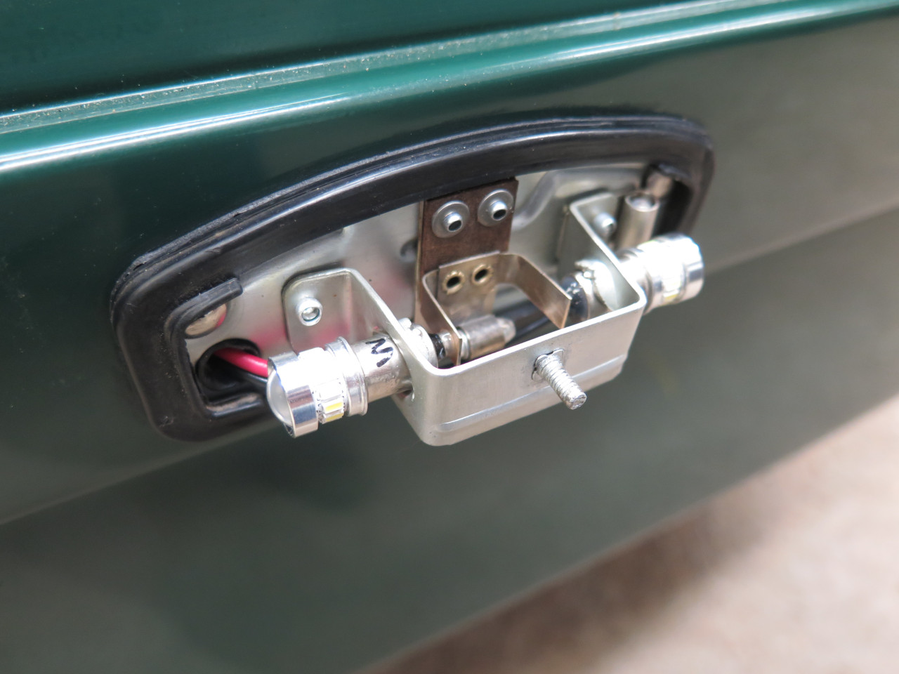
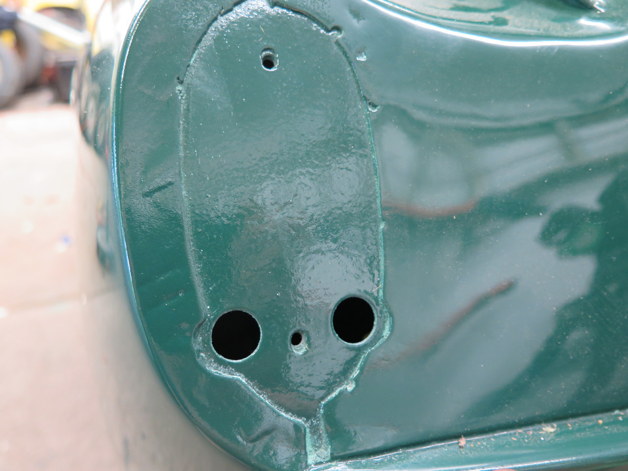
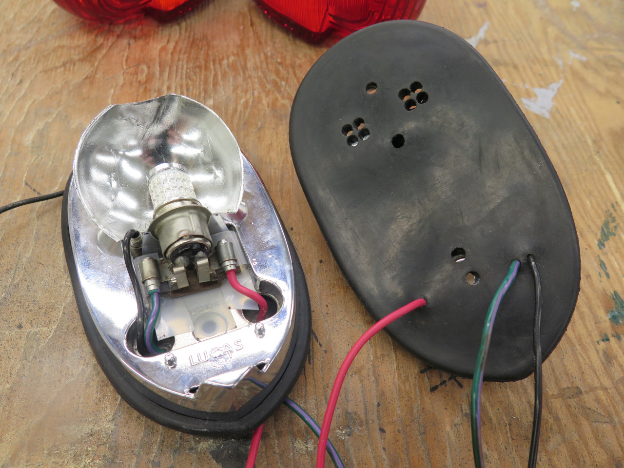
The tail/brake lights were a little more trouble.
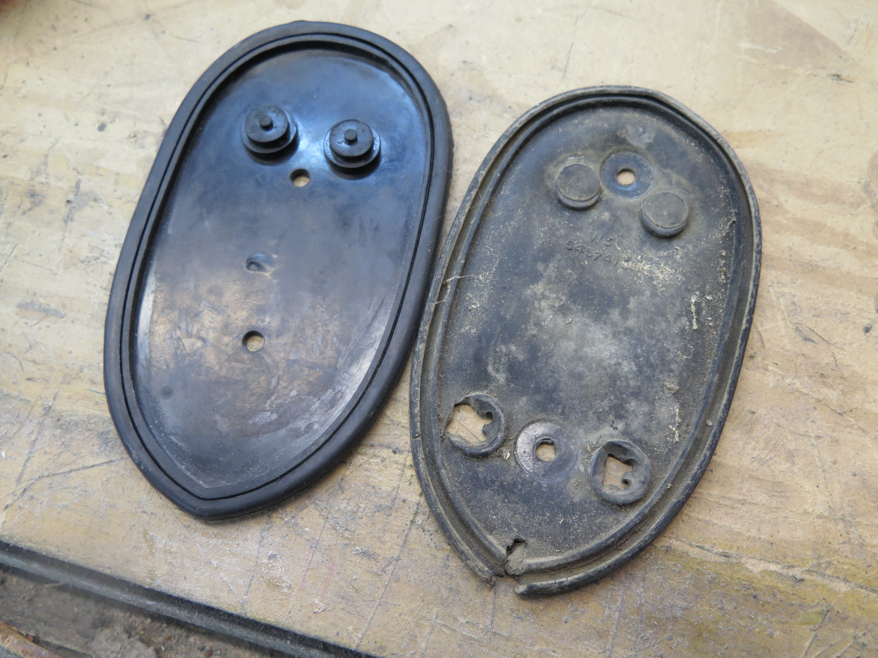
I ordered new rubber mounting pads. New on the left, old on the
right. Note that the new piece has the wire pass-through bosses on
the top, but they need to be on the bottom. Note that the
mounting holes are in the wrong places. Note that the top bosses
don't even line up with the holes in the fixture base. This is
clearly either the wrong part or a poorly made part. I looked
online at pics from other suppliers, and they all appeared to be the
same as the bad one I got.
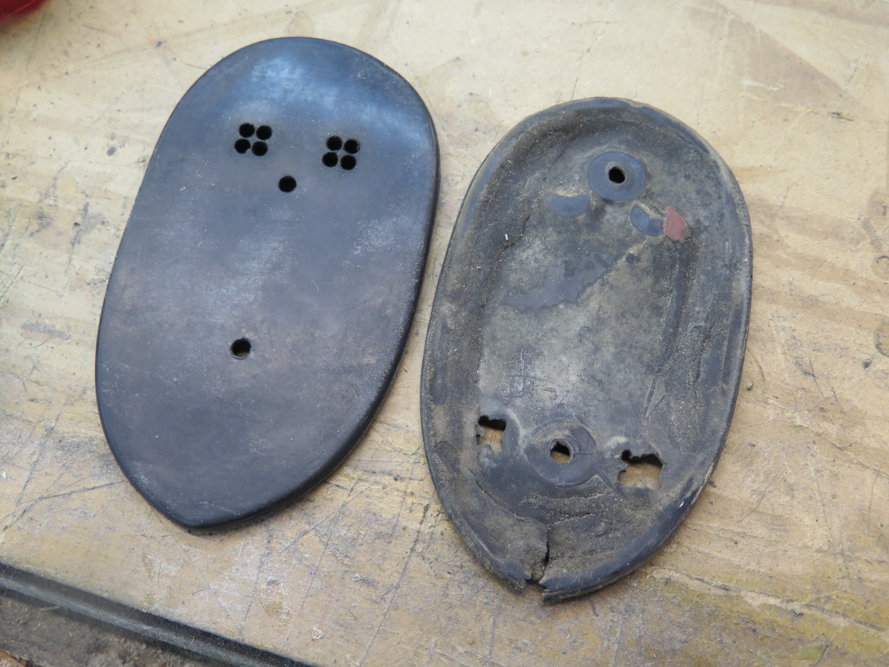
Since there was apparently no point in re-ordering, I just fixed the
parts I got. Shaved off the top bosses, new mounting holes, and
new wire pass-throughs. Irritating, but not a crisis.
When applying strip caulk, I often leave a little gap at the bottom, so if water does get in, it won't be trapped.
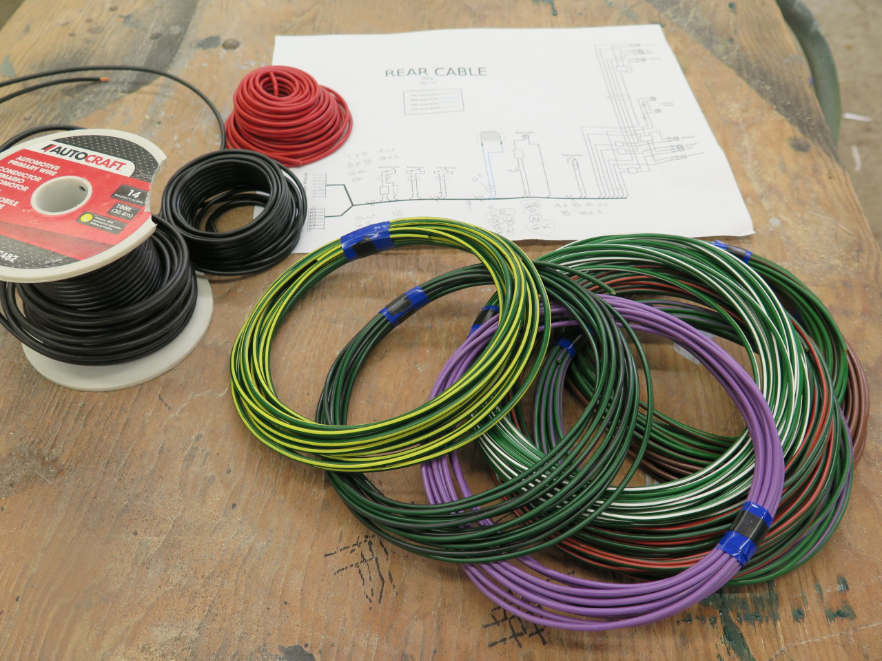
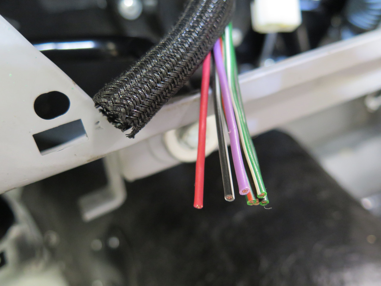
Now to wire 'em up! I drew up schematics for the cable and the
devices it connects, and assigned colors to the wires, trying to follow
the British BS-AU7 Vehicle
Wiring Color Code as closely as possible. I gathered the wire I
needed. I could find most solid colors locally, but the wire with
striped markers came from a specialty company. British automotive wire
for these cars wire is measured differently than in the US. They
specify the number of 0.3 mm strands in the wire. Most wire in
this car is 14 strand, which is very close to 18 AWG.
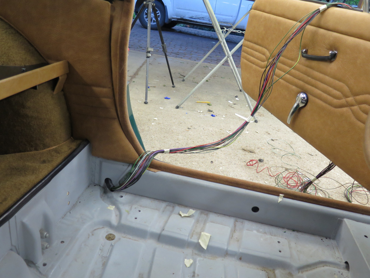
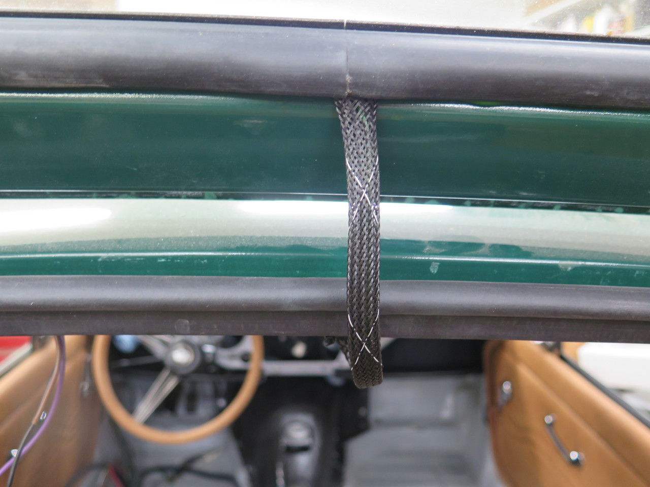
So, where to start? Well, the middle, of course. I bundled
the necessary wires together, and fed it into the conduit leading from
the cabin to the rear, under the trim. There are 14 wires at this
point in the cable.
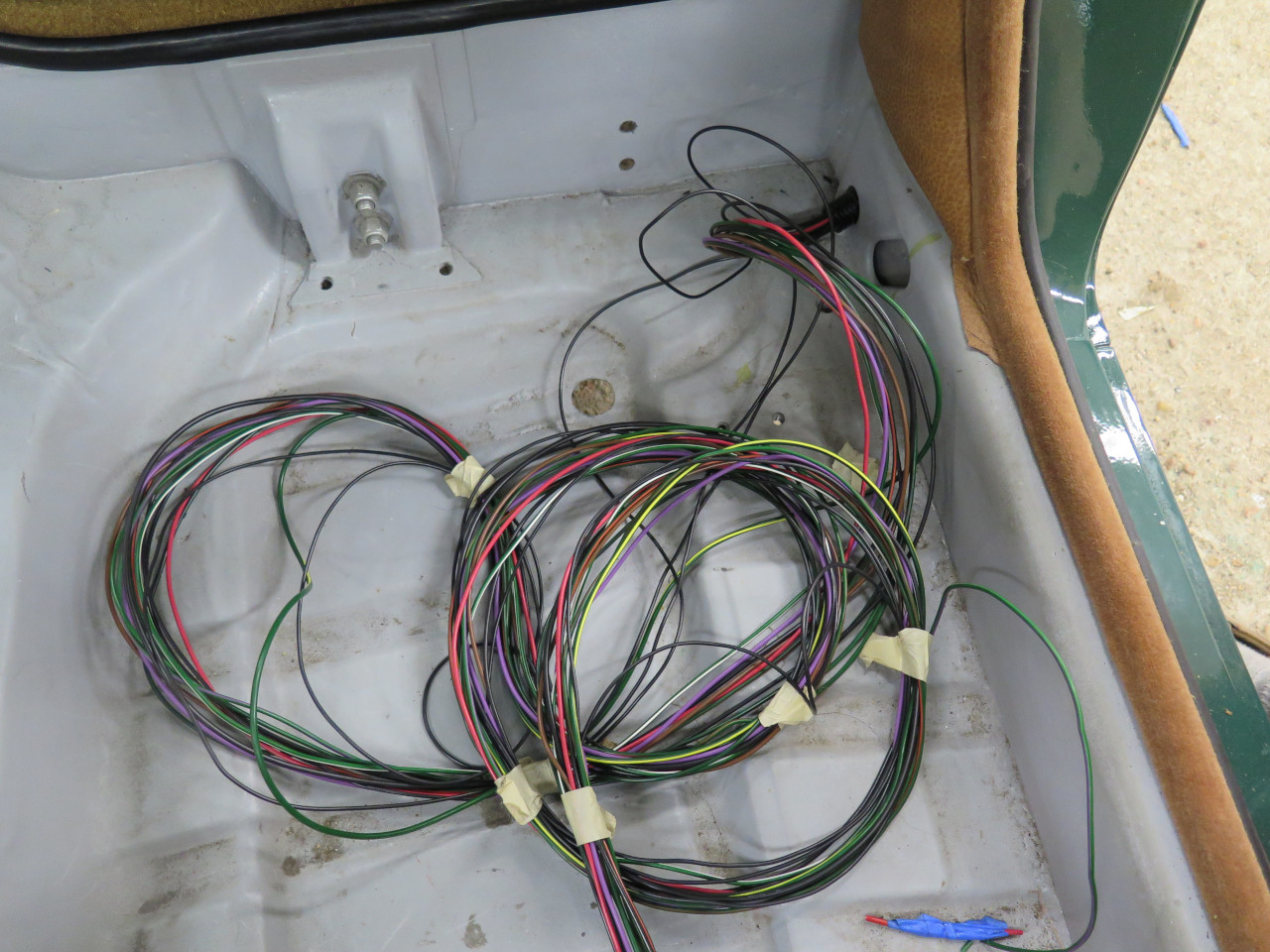
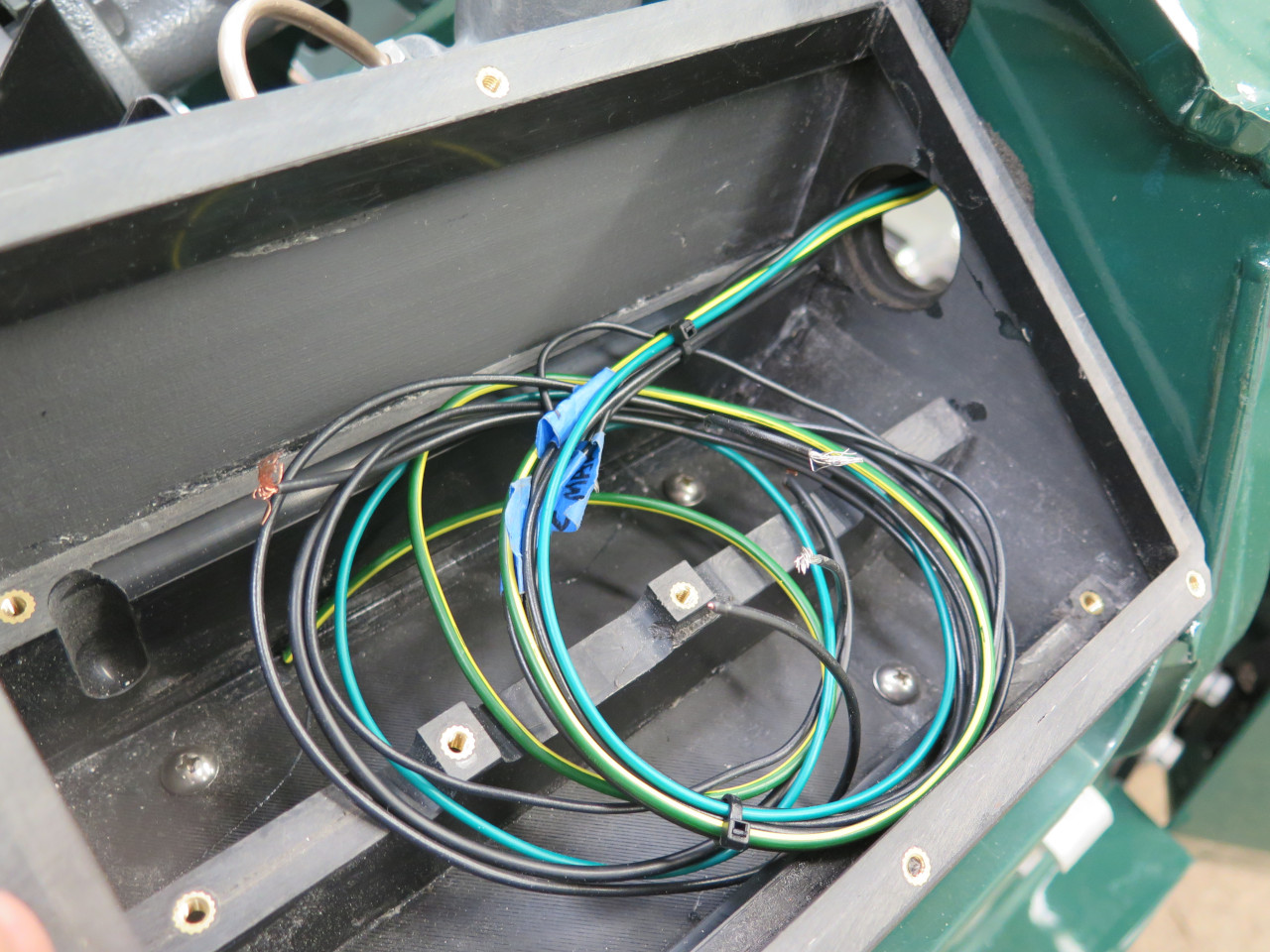
The wires emerge in the spare tire well. The smaller cable is the pigtails from the left side lights.
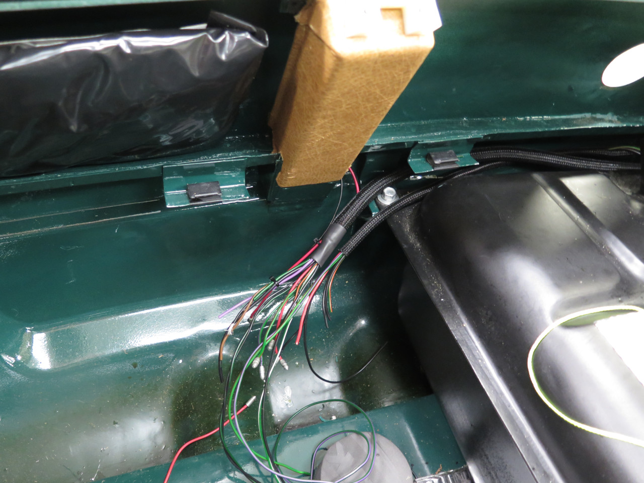
With all the connections made. The cable to the picture left goes to the
right side lights. The third cable on the right side of the
picture goes up to the dome light and the rear defroster. I try to
make all connectors fairly easily accessible, which is why I brought
everything to the spare tire well. There are wired grounds for all
of these lights. They are combined to a single ground wire for
the left side, and one for the right. Even though the lights no
longer rely on the body of the car for a return, they are still
electrically connected to the body, so I guess I consider the body a
redundant backup return path.
A two-wire cable also splits off to go to the fuel sender.
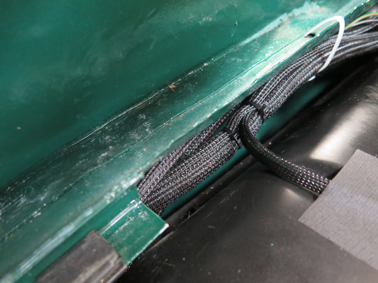
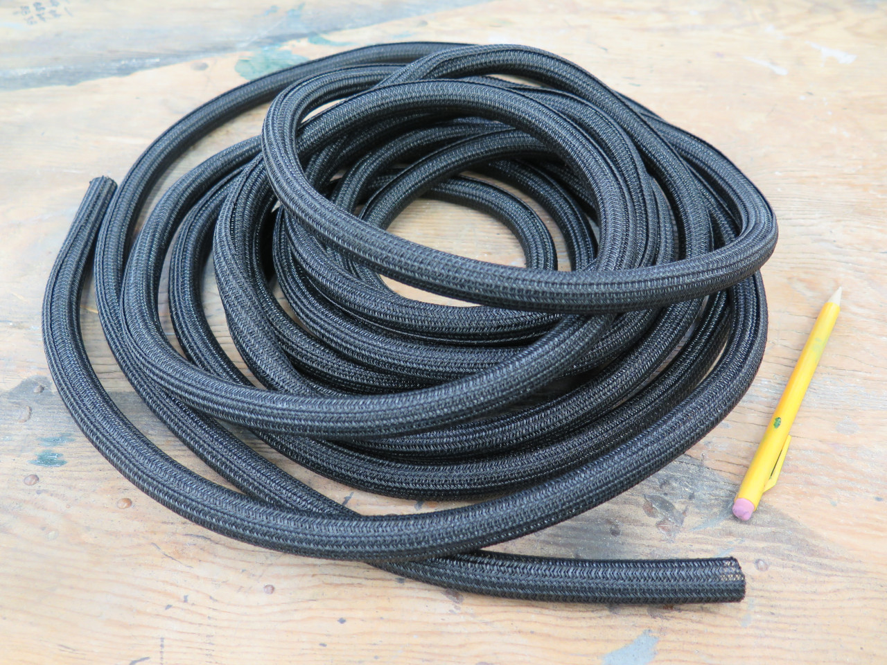
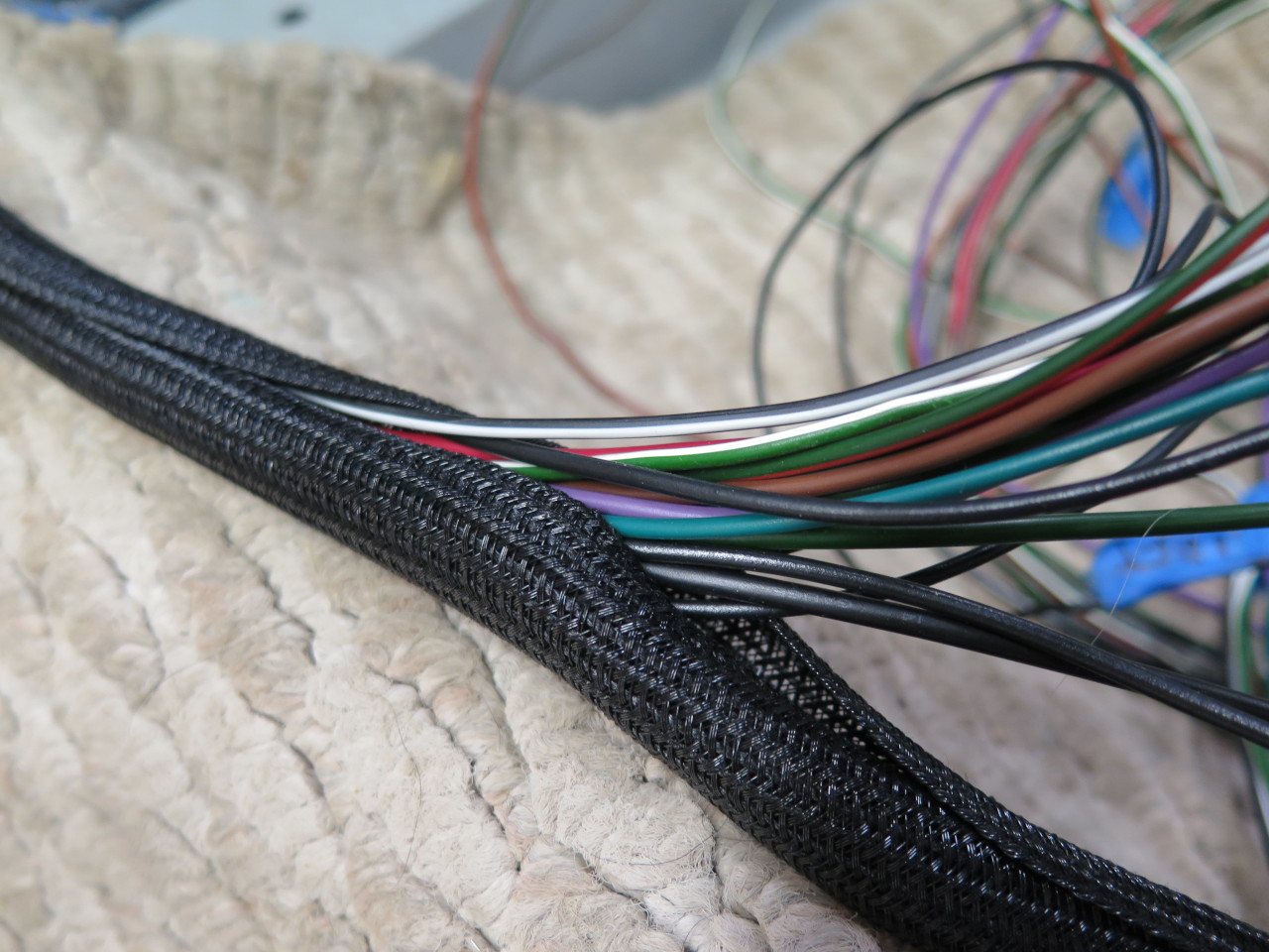
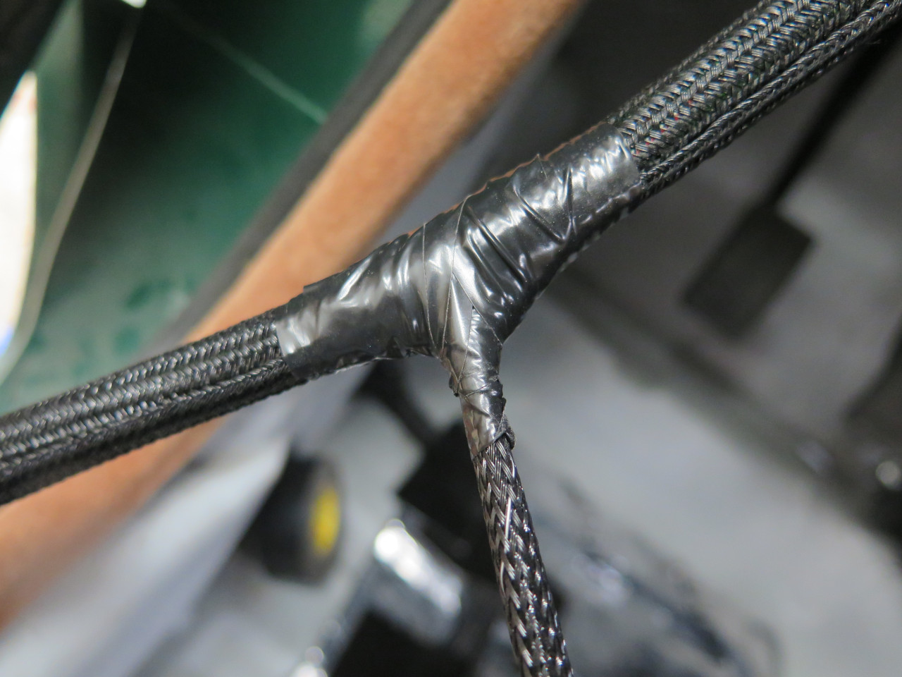
To protect the wires and bind them into cables, I'm using this
wrap-around sleeving. It's tightly curled, but expandable. I
like it better than wrapping with tape because the wires can still
move, making the cable more flexible. Also, the sleeve can be
opened to add or remove wires.
Sanity check:
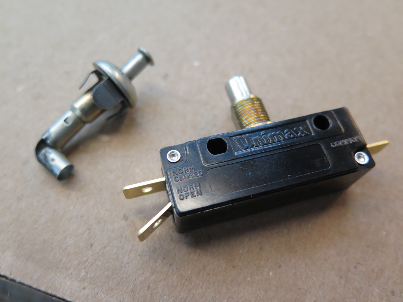
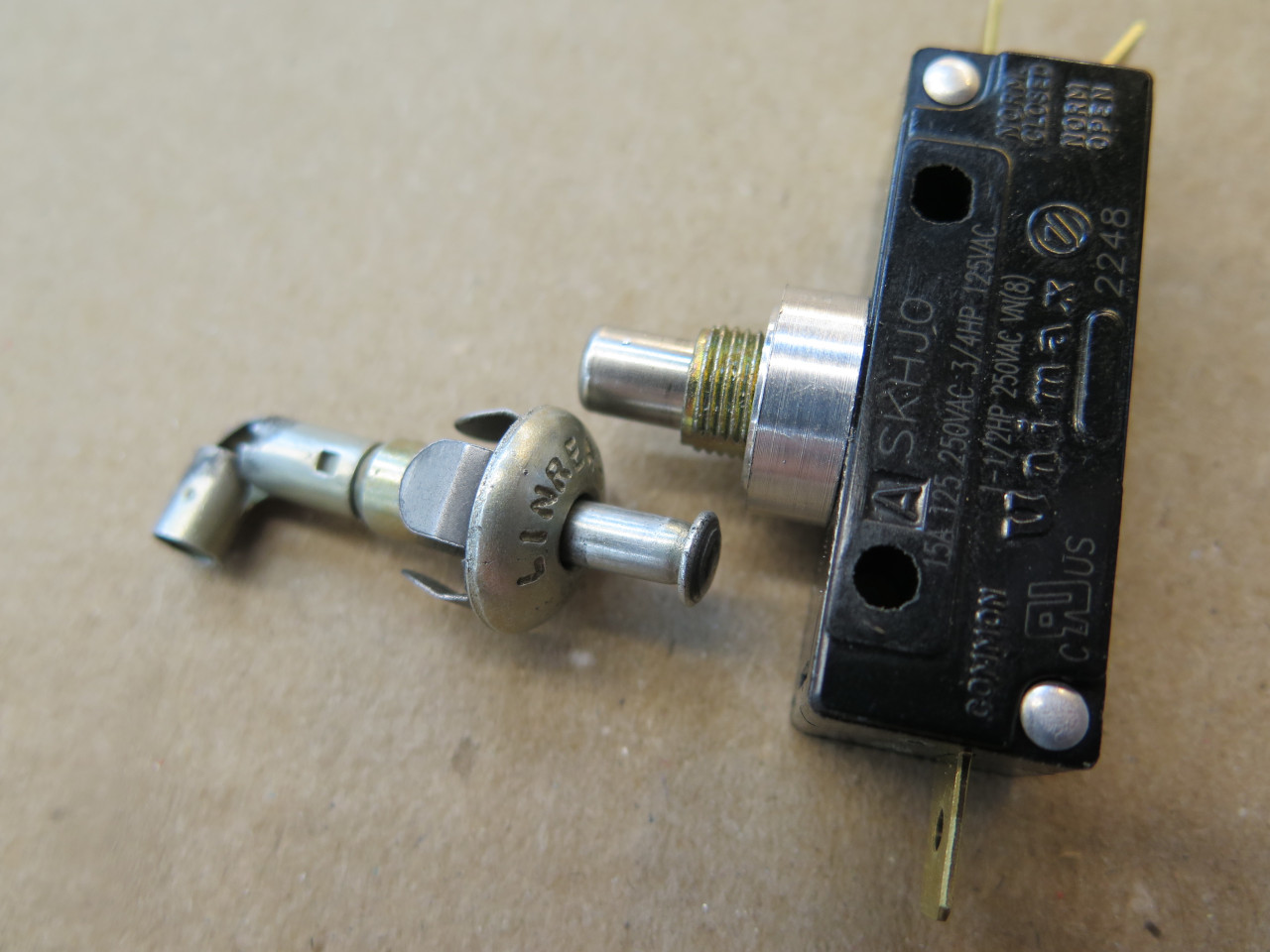
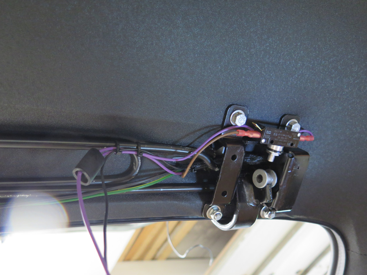
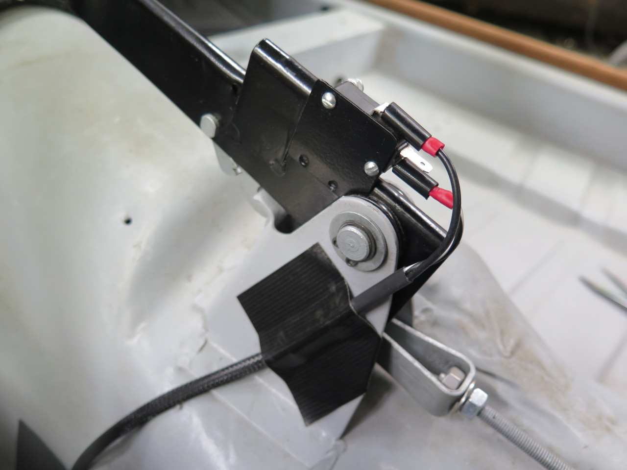
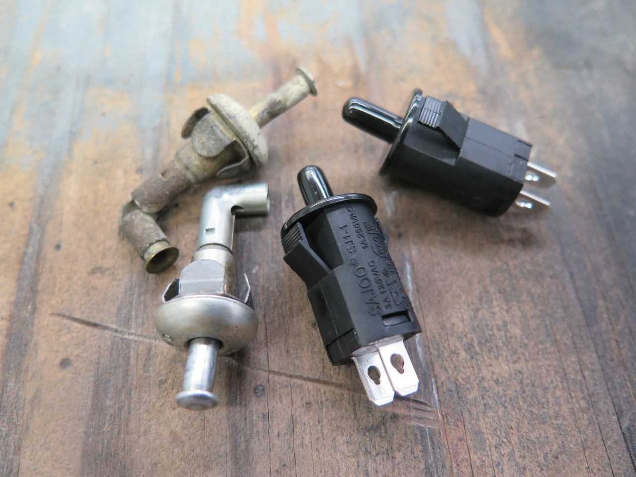
Now up to the dome light area. There is a dome light switch
attached to the hatch hinge assembly that closes when the hatch is
open. Originally this was a "low side" switch, meaning that it
switches the ground. For some technical reasons, I had to change this
to a "high side" switch, which switches power instead. This meant
that the original switch wouldn't work, since it has one since grounded
through it's mounting tabs. I ended up with this plunger
switch. I had to add a little aluminum spacer to the mounting
barrel to duplicate the position of the original plunger. The
switch barely fits under the hinge cover.
The wires for the demist element on the rear window jump from the hinge
cover to the hatch, where they run under the lip of the window
seal. The demister wires are 28 strand, close to 14 AWG.
Moving forward now, trying to make sense of this:
I added a parking brake indicator light to the dash, and this is the switch for it on the hand brake lever. Cable branches are typically secured with electrical tape.
Next branch is for the reverse switch. I realized with disgust
that I had neglected to connect wires to the reverse switch before
installing the gearbox cover. The thought of removing the cover
again was so repugnant to me that I thought cutting a rather large
access hole and making a cover was far preferable.
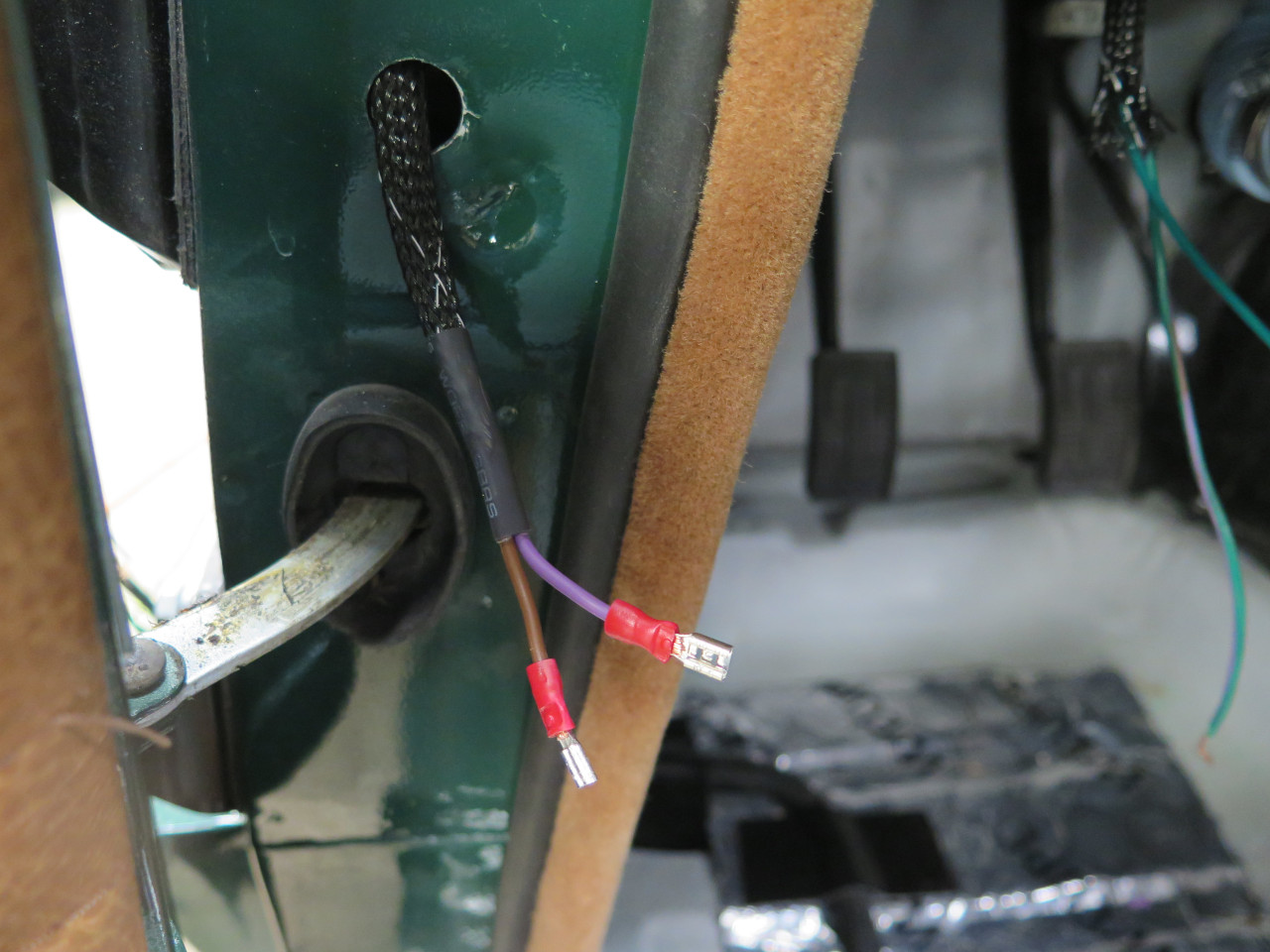
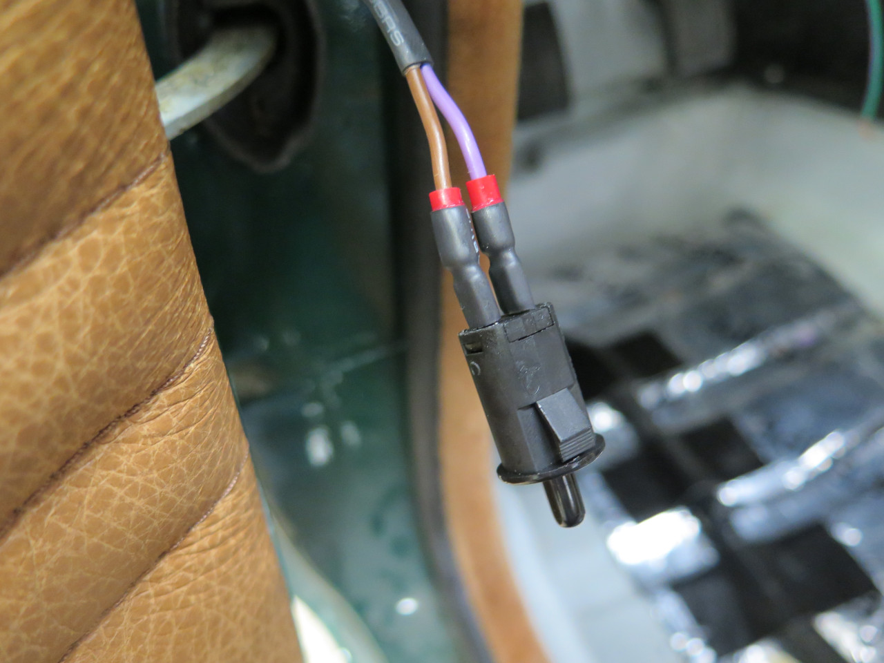
Then there was a branch to the left side door switch for the dome
light. This too had to be a high side switch, so the original
switches wouldn't work. I found these plunger switches that work
well. The holes had to be enlarged a bit. I squirt a little
dielectric grease into all bullet and spade connectors to try to keep
moisture out.
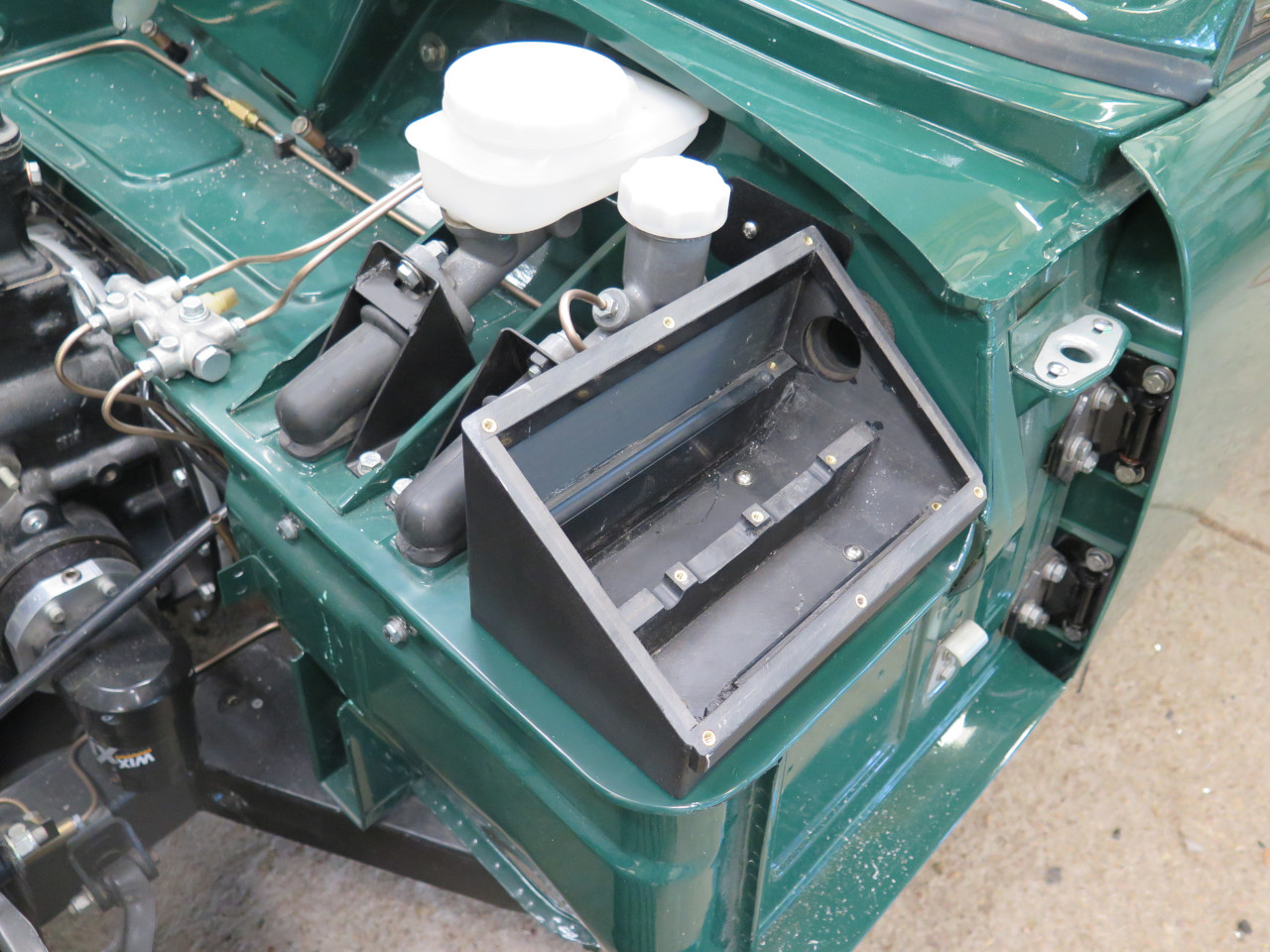
The next stop on the cable was to drop off some of the wires at the Power Module. But that required the PM to be mounted.
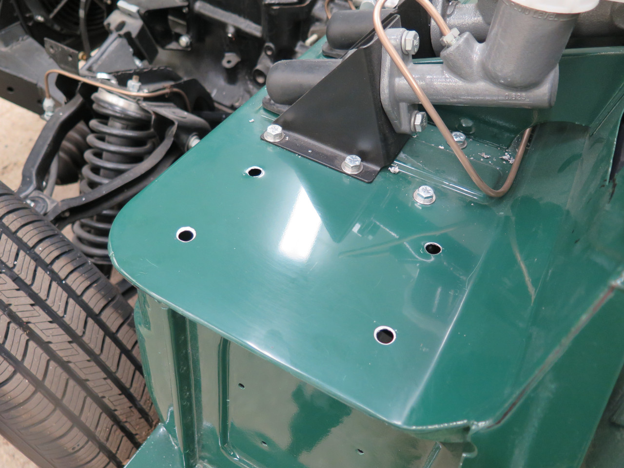
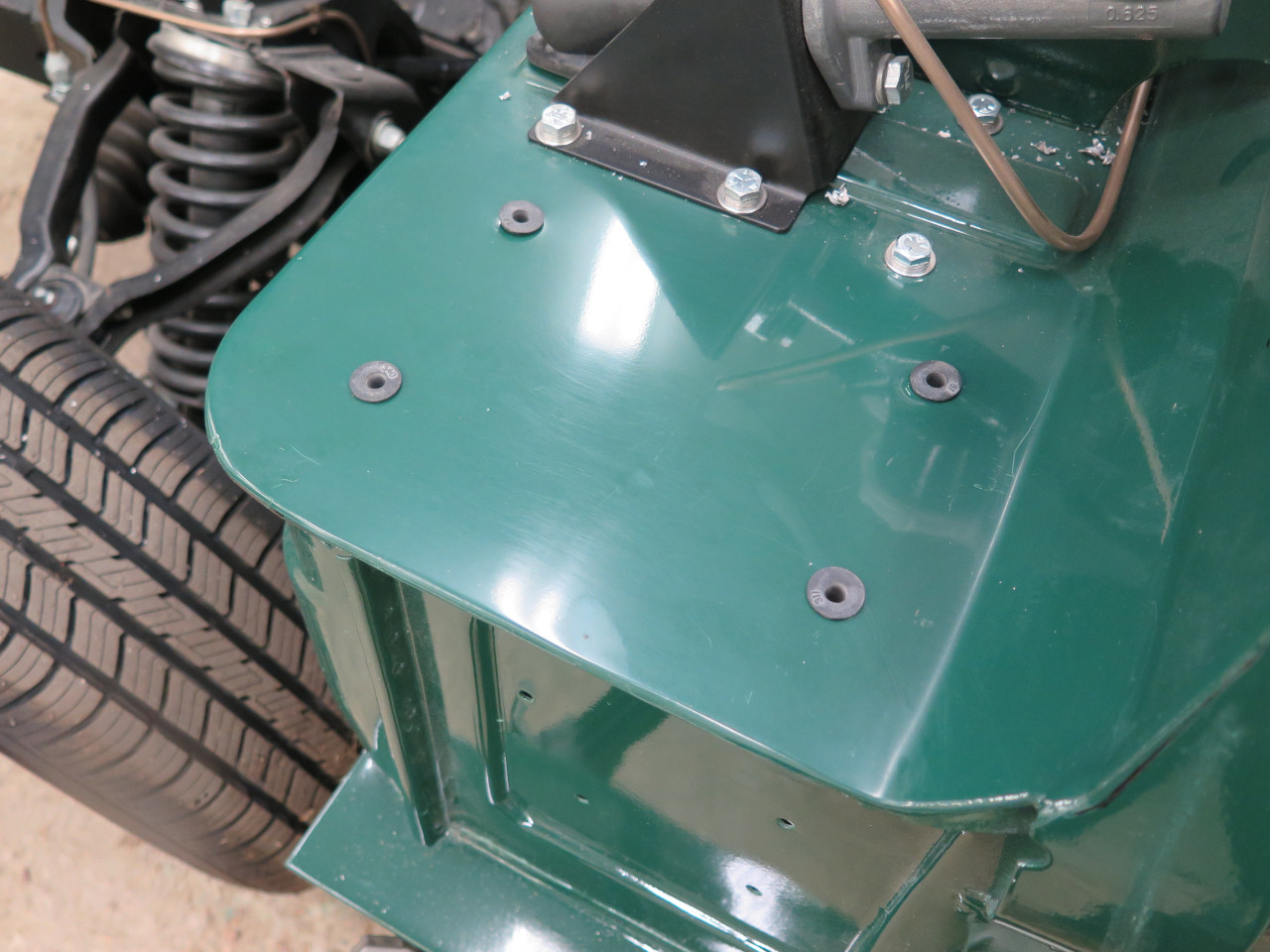
The PM goes on the shelf just outboard of the master cylinders.
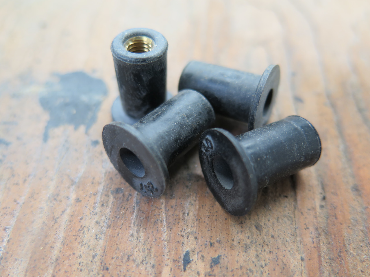
Four mounting holes and some "well nuts", which are rubber isolated
fasteners that give a resilient attachment that reduces transmission of
vibration.
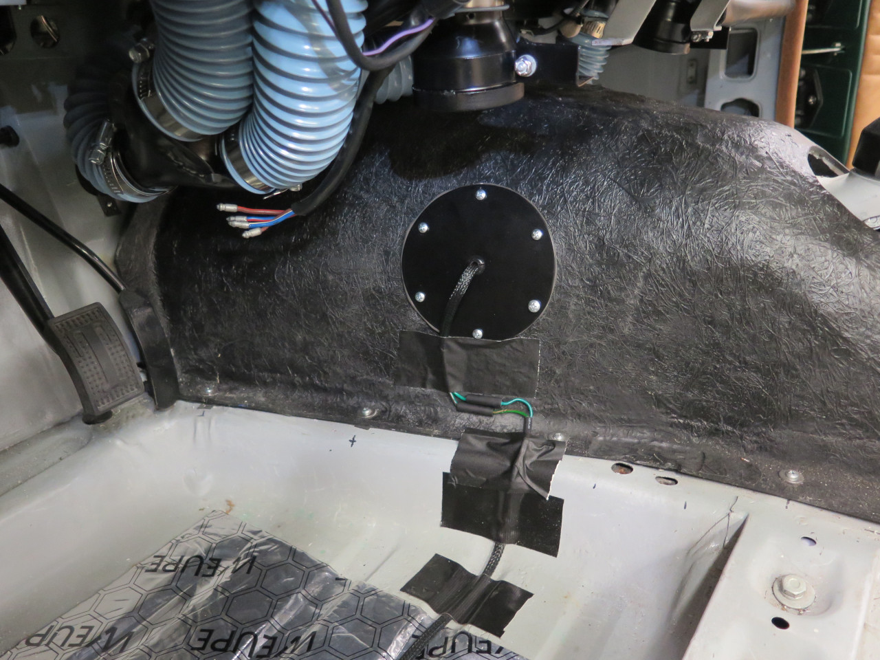
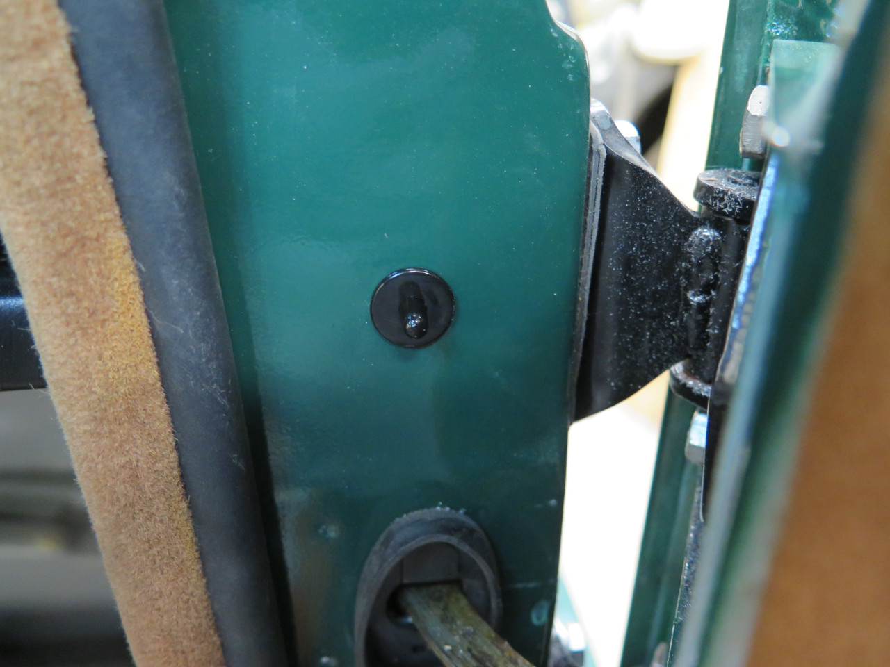
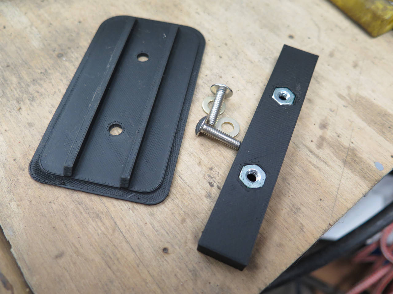
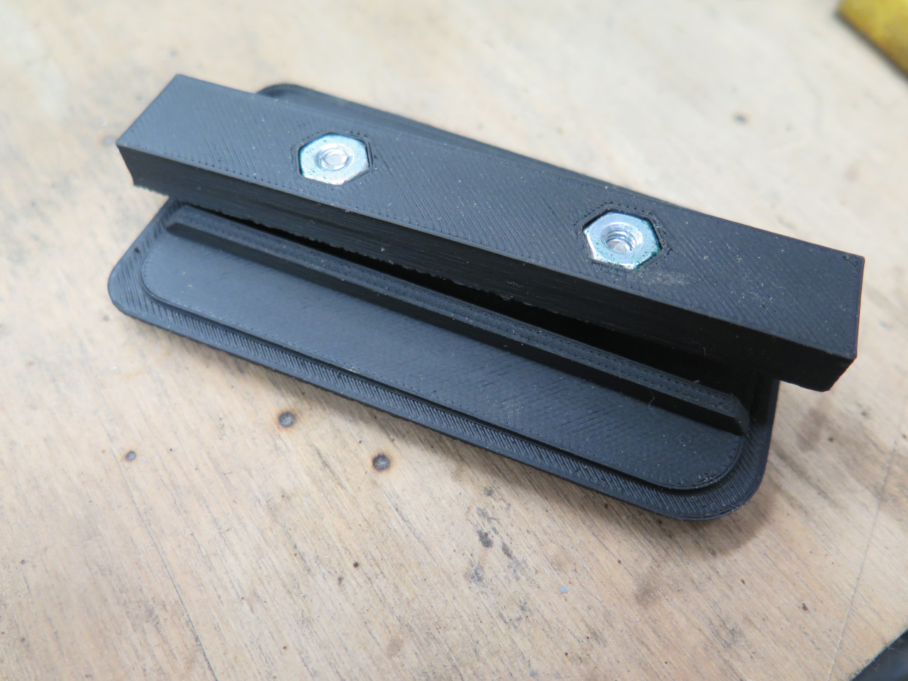
A little housekeeping before actually mounting the PM box. There
is a gaping hole in the firewall where the original fuse box went.
I usually prefer mods that are reversible, so rather than welding it
up, I made a little 3D printed blanking plate for it.
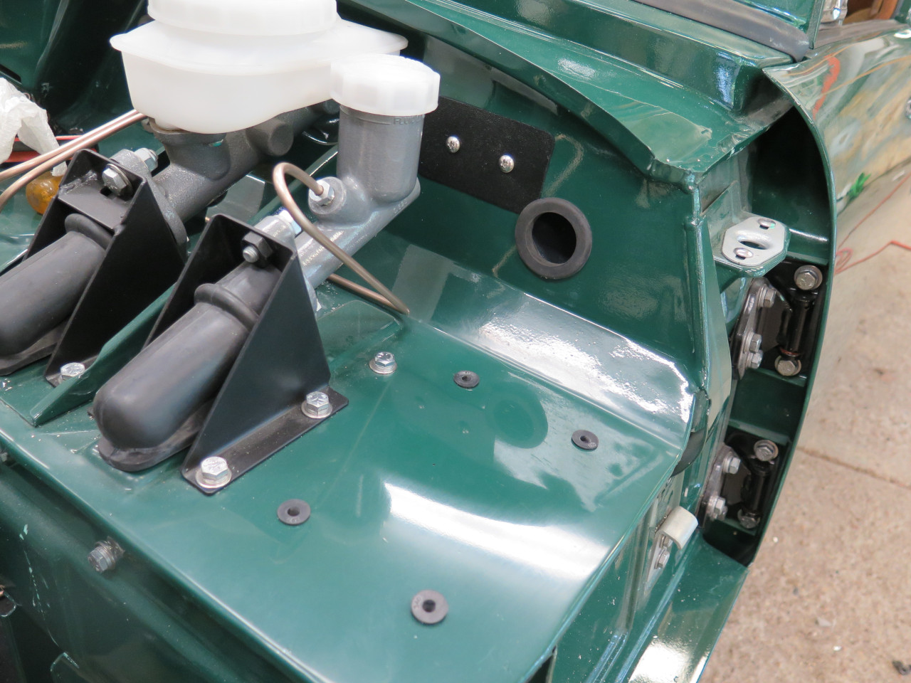
Then cut a hole to allow access between the inside of the car and the
PM, and applied a nice grommet. The first pic shows why the mod to the parcel tray was necessary.
Then a closed cell foam weather seal gasket.
The first of the wires to the PM. There will be quite a few more from the front cable and the dashboard.
The cable then goes along the firewall with a branch to the brake
switch, and a branch to the right side door switch. The rest of
the wires go the the center dash, where they get connectorized.
In principle, this cable, though it was built essentially in situ,
could be removed from the car in one piece. In practice, this
would be difficult with the trim in place, so I don't want to do
it. This is what the forward part of the cable looked like before
all of the terminations were applied.
Making this cable took a while, bit nothing compared to the planning and
design work that went before. There was one snafu: During
the sanity check, I powered the cable and shorted the brake light
wires. I walked to the back of the car to see, brilliantly
blazing, the backup lights. I traced it to a bug on the wiring
diagram, where I had accidentally swapped wire colors, and then
dutifully built the cable to the drawing. This is one place where
that wrap-around sleeve saved the day. It made the fix relatively
easy.
There may be close to $100 in wire, sleeve, and connectors.