To my other GT6 pages
February 9, 2023
Power Module
It's a pretty common opinion among owners of LBCs of this era that one
of the worst parts of the cars is their electrical systems.
Finicky switches, underpowered motors, absolute minimal use of fuses and
relays, and poor grounds conspire it give us a fickle and failure prone
system. Not many of these cars of a certain age have not had
electrical problems in their history. The use of only three fuses
for the entire system is particularly unconscionable, and even dangerous
in my opinion.
In my research, I found that replacements are available for most parts
of the electrical system, including the wiring harness itself, but this
route didn't really address any of the original design weaknesses.
There are also at least a couple of "upgrade" systems available that
improve he design by including additional relays and fuses. I
looked at a couple of these these pretty closely, including their
schematics. They both seemed well thought out, and though they
differed a little in design philosophy, it seemed to me that either one
would be a big step in the right direction.
However, neither of these systems really address one central
problem: circuit "grounds" (aka "earths", or "returns").
These cars, like most cars, routinely use the body of the car as the
return part of electrical circuits. This typically works fine when
the car is new, but with some age, we start to see continuity problems
in ground connections that often consist of dissimilar metals in areas
that can be exposed to moisture.
Then there was also the glaring fact that I had grossly modified my dashboard, so any of these off the shelf products would have to be modified.
I was lost mulling over thee options when Inner Engineer burst into the room, riding a unicycle.
"Wassup?" he said annoyingly, balancing back and forth behind me.
"Oh, I'm just trying to decide what to do about the GT's electrical system."
"So what's wrong with it?", he asked, plopping down into the chair next to me.
"Well, just about everything. Only three fuses and one relay, for starters."
"Wow, talk about minimalist."
"Right. And the grounds have always been a problem."
"Did you any new circuits?"
"Yes, rad fan and seat heaters. And a parking brake switch."
"And you fooled with the dash too, didn't you?"
"Yeah. Nothing made for a stock layout is gonna work out of the box."
"Kinda designed yourself into a corner, didn't you?"
"Yeah. Looks like it."
He paused, apparently mulling. Then a little smirk. "Seems like you only got one option left, Dude".
I hesitated, re-shuffling all of the possibilities. One of them kept rising to the top. "Custom system?"
"Right on. You have the skills."
"Yes, but there's got to be a better way."
"A better way than a bespoke system made for your exact car, with the
chance to fix all of the factory short cuts ? Come on, Dude, man
up."
In my heart, I knew he was right, yet I still protested weakly. "It would take a long time."
"Yes, but it's winter, Dude. You aren't working much in the garage
anyway. It's mostly computer and shop work. Besides,
how---"
I cut him off in mid-sentence. "I know! How hard could it be?"
He climbed aboard the unicycle. "Piece of cake!" he said over his shoulder as he lurched out of the room.
I suddenly realized that this exchange put me on a new a plateau of
clarity. I would include relays for each circuit above a certain
current, and each circuit would have dedicated fuse protection.
All loads would have explicit wired return paths to a single point
ground bus. All of the relays, fuses, and ground bus would be in
one easily accessible place. There would be some simple
diagnostics included, too.
I went looking for a place to put this "Power Module", as I was calling
it. I wanted it easily accessible, so behind the dash wasn't
ideal. Somewhere under the bonnet would have great
accessibility, but ambient temperature would have to be a
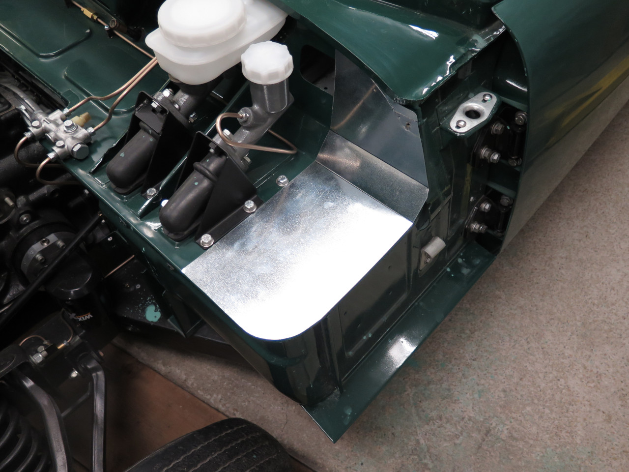
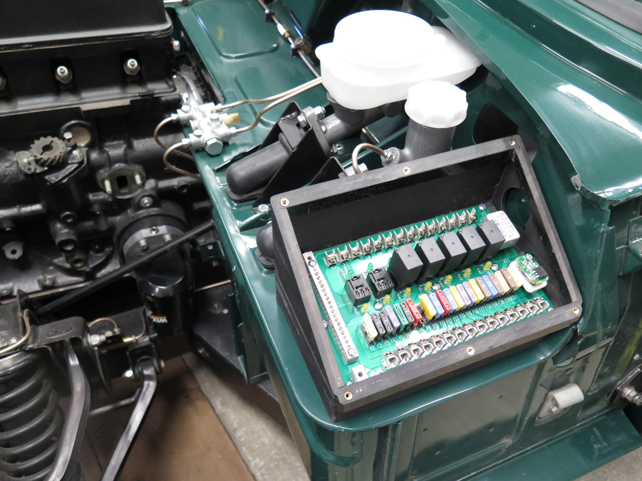
consideration. In the end, I chose the flat area on the deck just
outboard of the master cylinders.

This seemed to be a good location, but I was worried about the
size. Could I fit everything into that space, including some kind
of enclosure, and a provision for cable entrance?
I wanted to make this Power Module PCB (Printed Circuit Board) based if I
could, but this presented some challenges. First I determined the
maximum size PCB that would fit. Then drew up a schematic
for the circuitry, and did a PCB layout based on it.
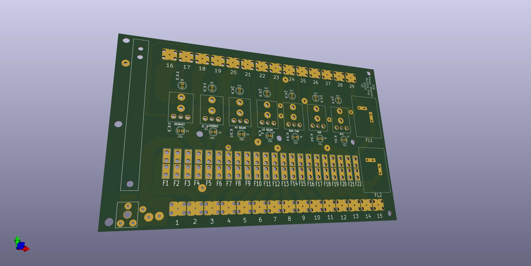
The board is 5" x 8". Not very big, considering some of the
largish currents that have to be handled. Large currents in PCBs
imply wide traces, which take up a lot of room. In some cases, I
had to include wire jumpers to handle some of the current.
I ordered the PCBs and started work on the enclosure.
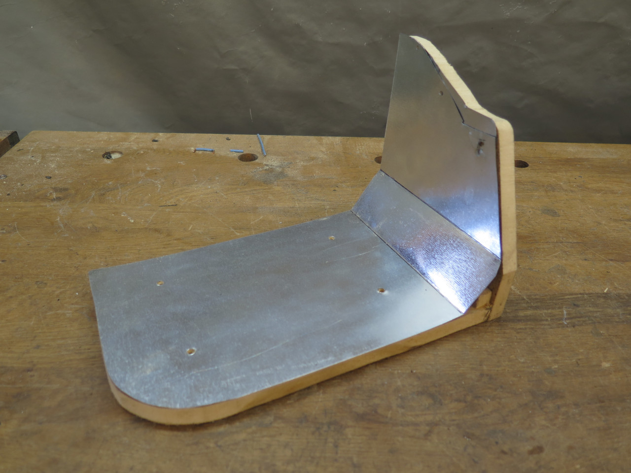
Since heating my garage takes time and energy, I wanted to do most of
this work in my warm shop. So I made a mock-up of the mounting
area that I could use in the shop. This is just some flashing
sheet metal that conforms to the area. It was attached to an MDF
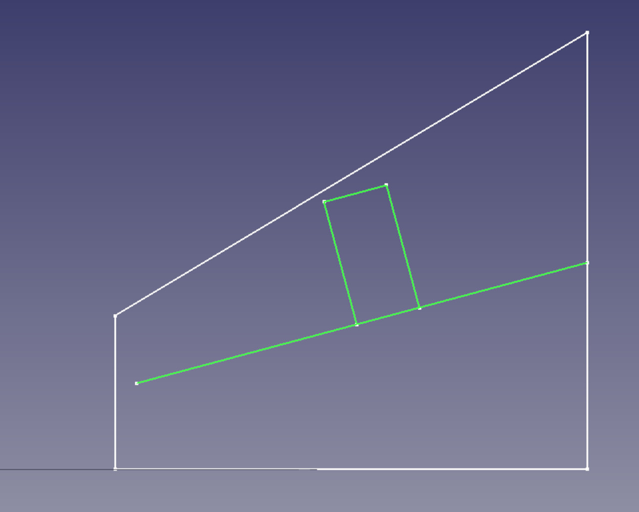
support to hold the correct shape. One complication is that the
vertical fire wall isn't at a right angle to the deck--it's about 95º.

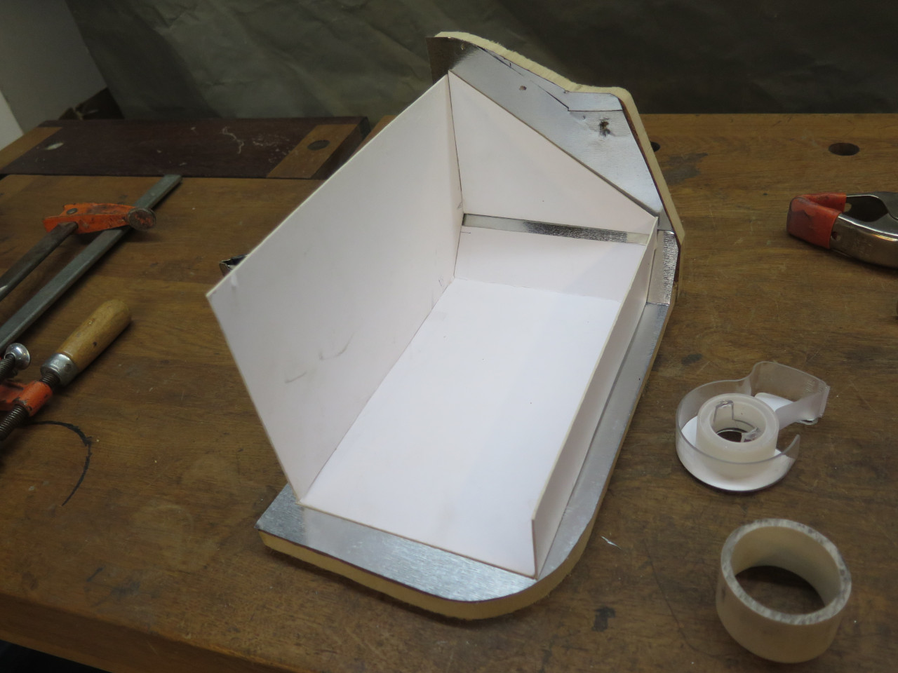
Then a couple of iterations of paper and cardboard trials.
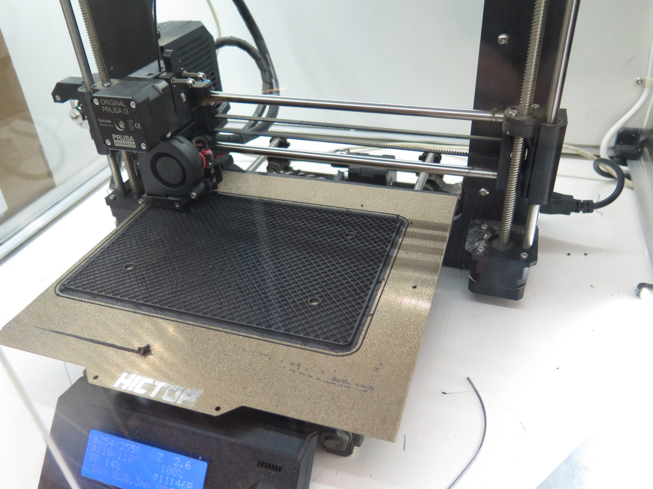
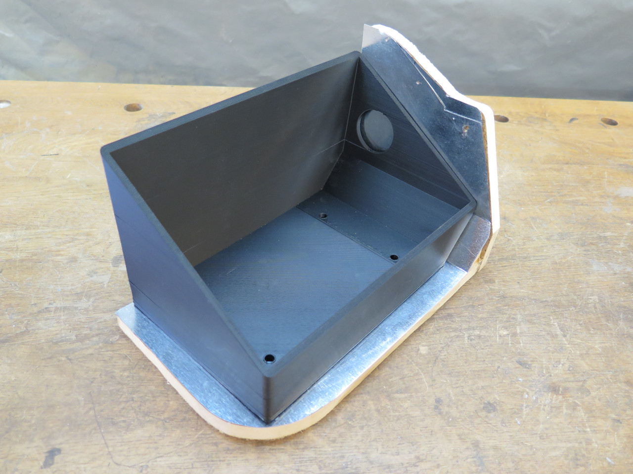
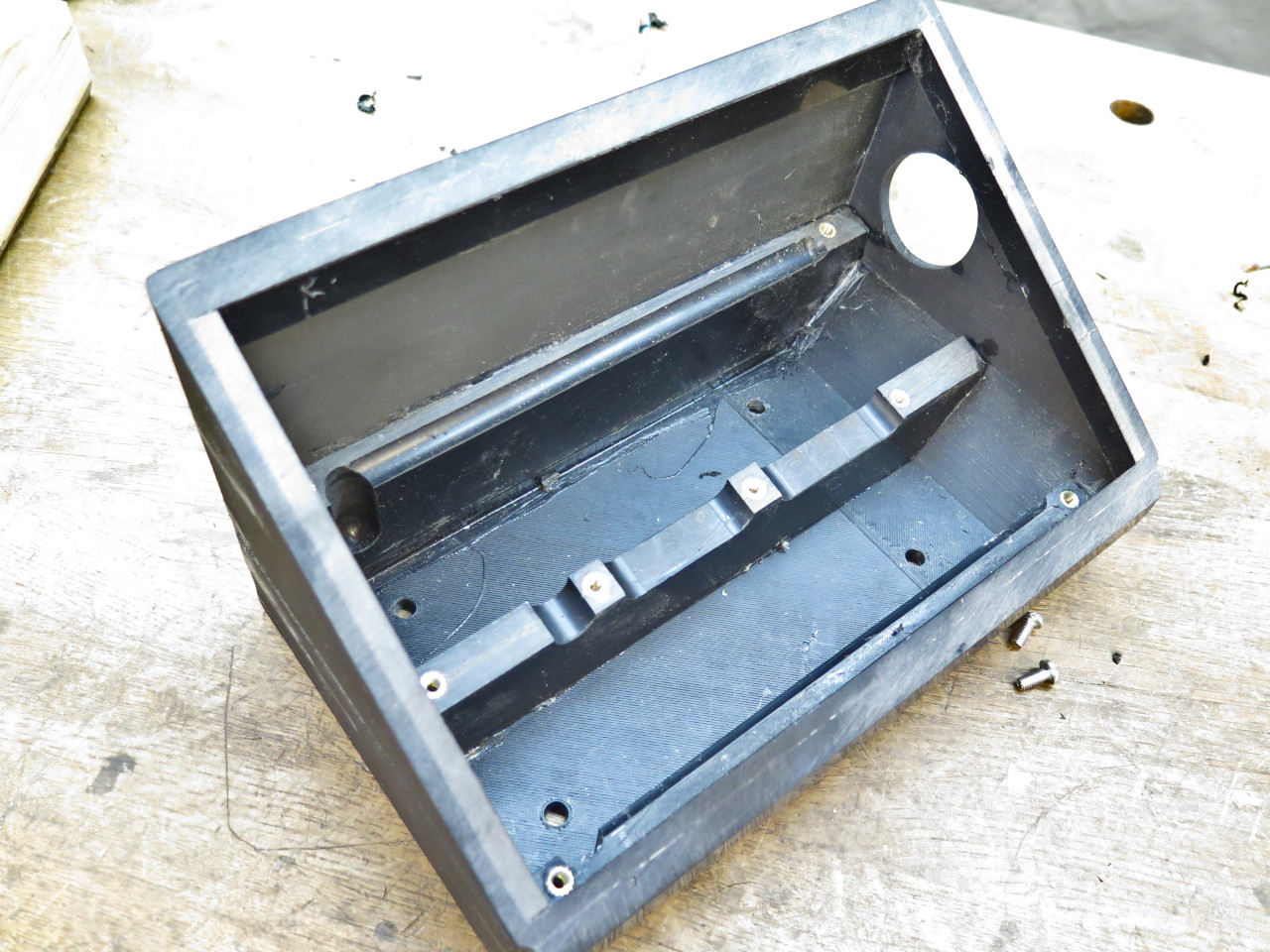
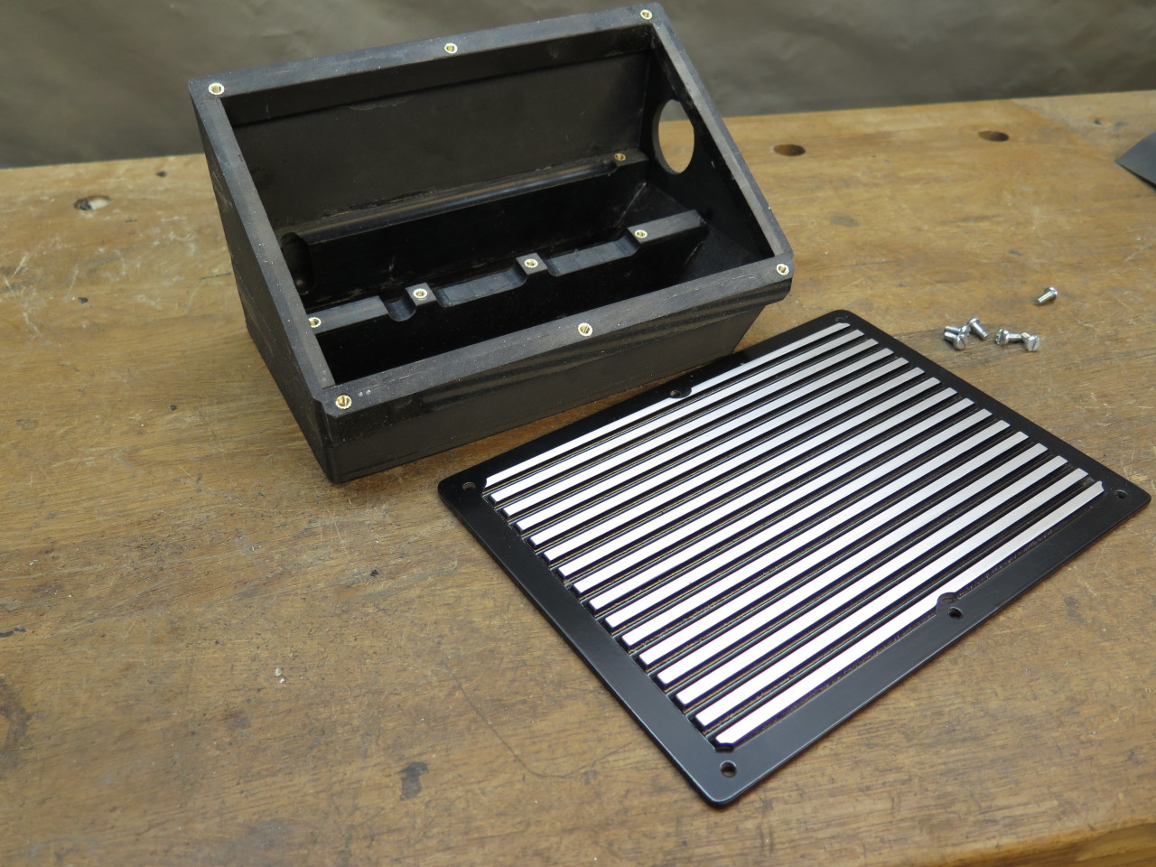
I considered making the box from PVC foam core panels, but in the end,
just 3D printed it. It took around 12 hours to print, but I could
be doing other stuff. It is peaked so that it could include that
circular opening. That's where the cable entrance to the box will
be. Bringing the cables into the box directly from inside the cabin will
eliminate some of the cabling in the engine bay.

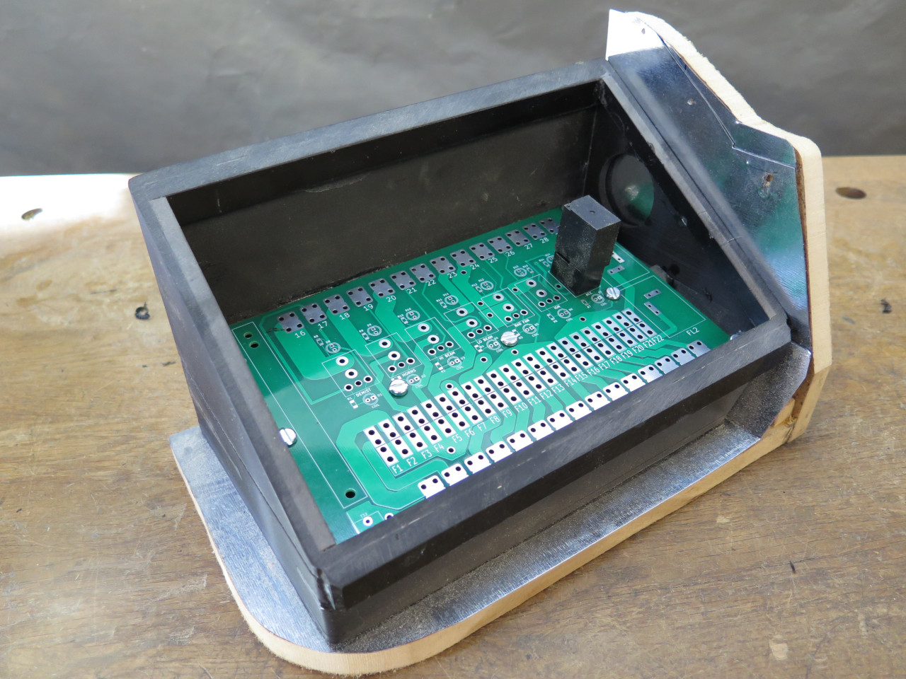
I didn't have the actual circuit boards yet, so a piece of poster board was a stand-in.
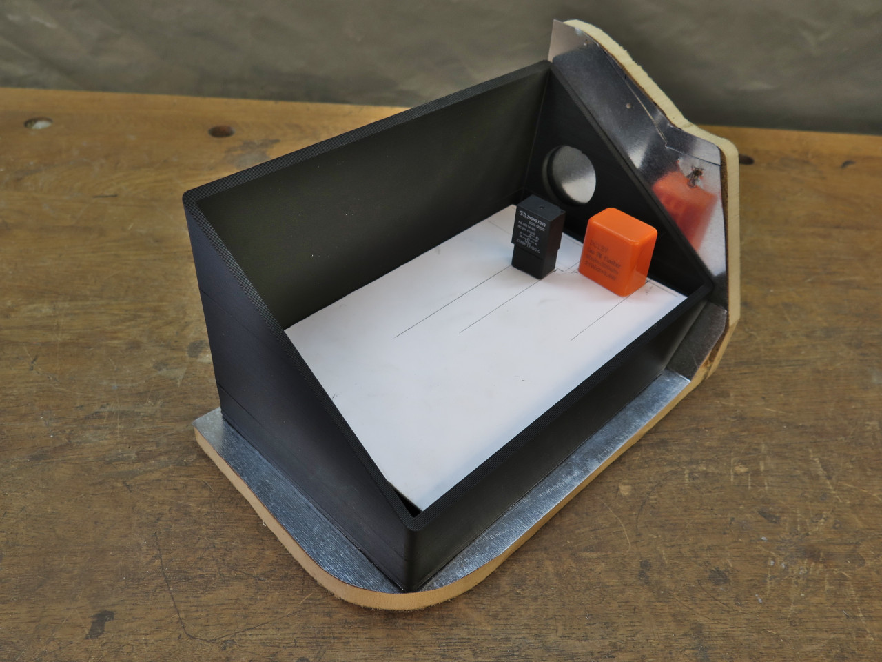
It turned out that mounting the PCB at about a 12º angle improved accessibility.
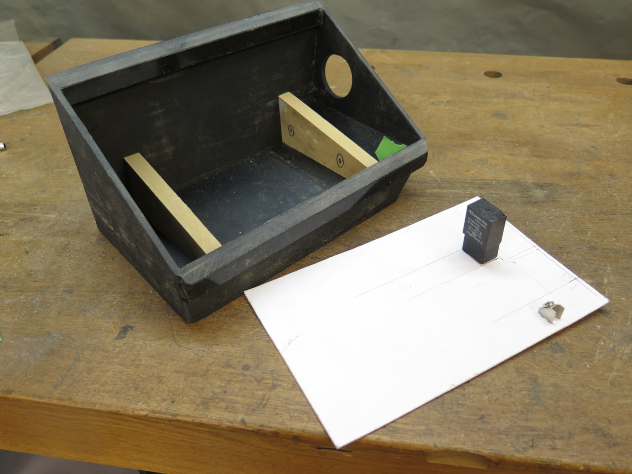
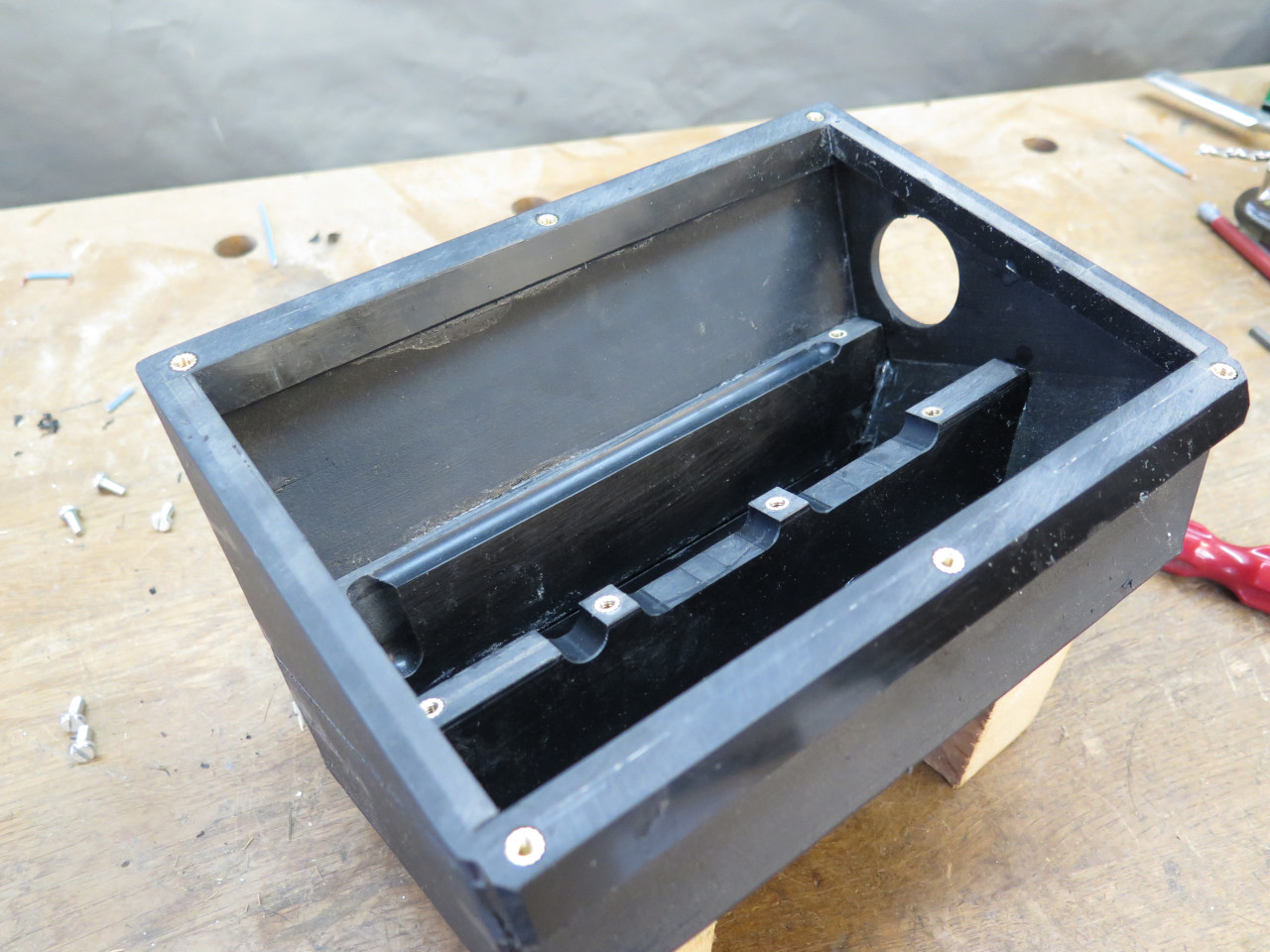
Some glued in solid ABS pieces provided support for the PCB as well as reinforcement for the box.
By this time, I had the PCBs.
To provide better threads for fasteners, I use these little
inserts. They are heated up by a soldering ion, and then sunk into
pre-drilled holes.

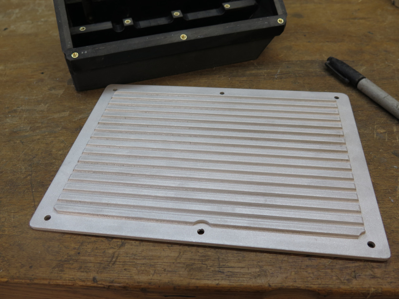
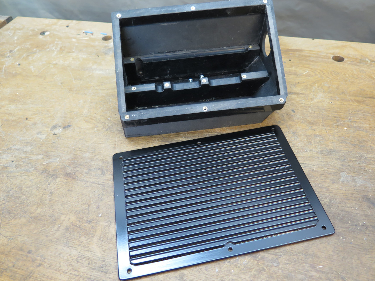
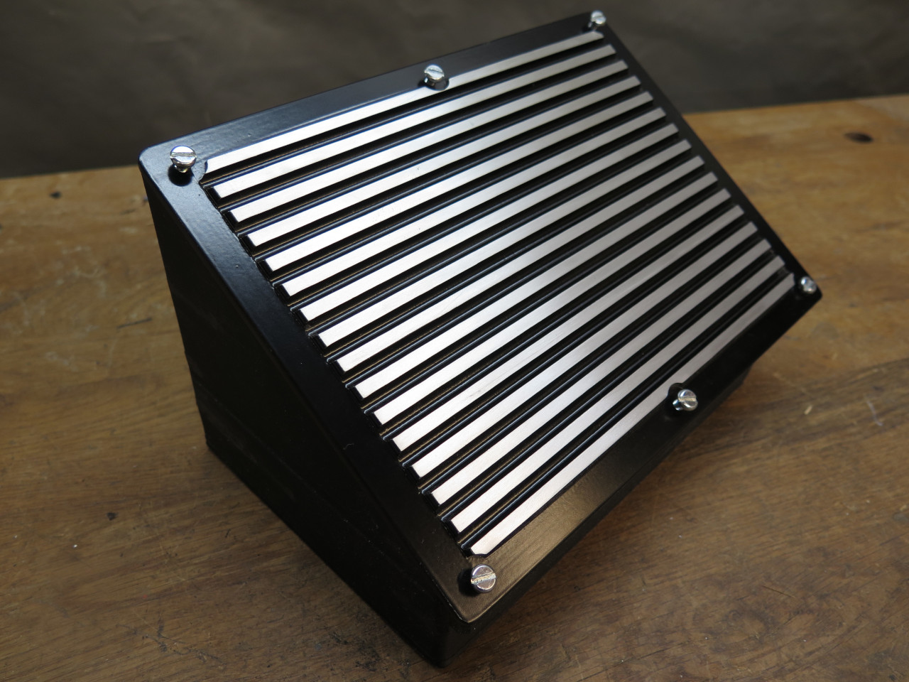
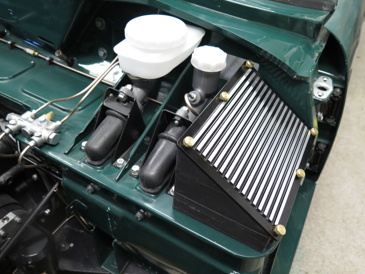
For a cover, I started with a 1/4" aluminum plate.
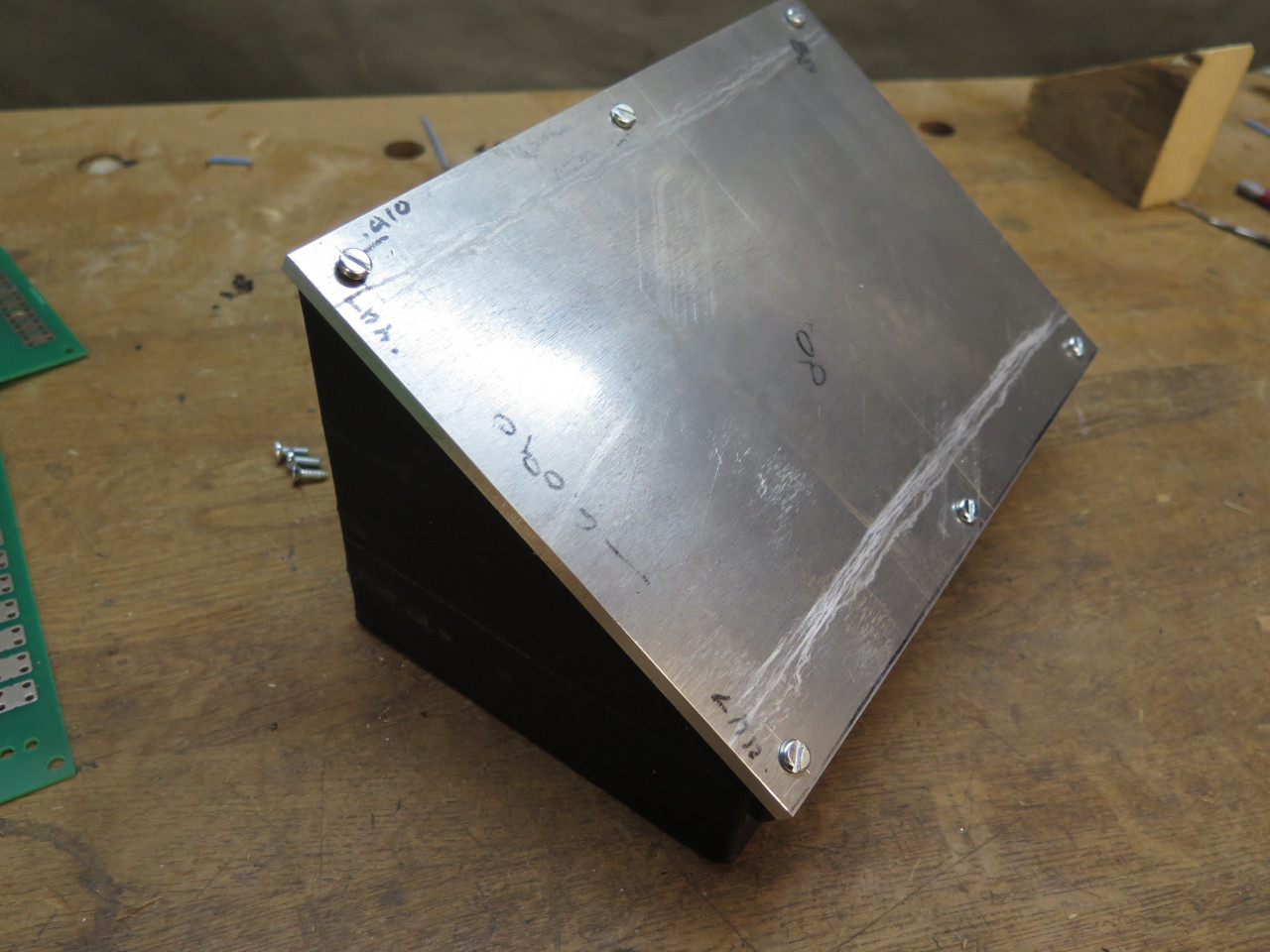
Milled some channels, powder coated it, and sanded the tops down. This was mainly to sort of mimic the valve cover.
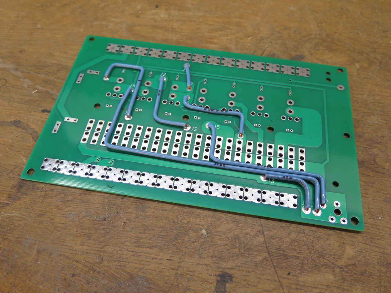
Then it was back to the PCB. Because of the tight dimensions and
the high-ish currents for some circuits, seven 14 gauge jumpers on the
bottom side augment the capacity of some traces.
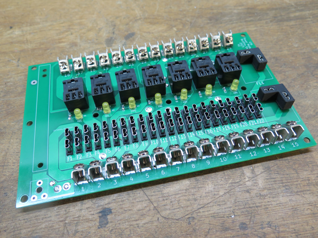
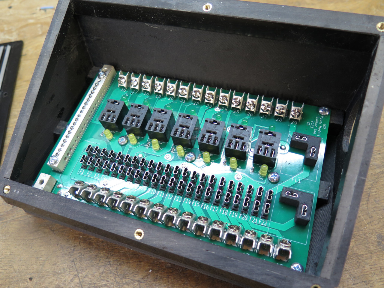
Then it was time to populate the board with relay and fuse sockets.

Space was too tight for typical barrier strips, so I used individual
screw terminals for connection to the outside world. I couldn't
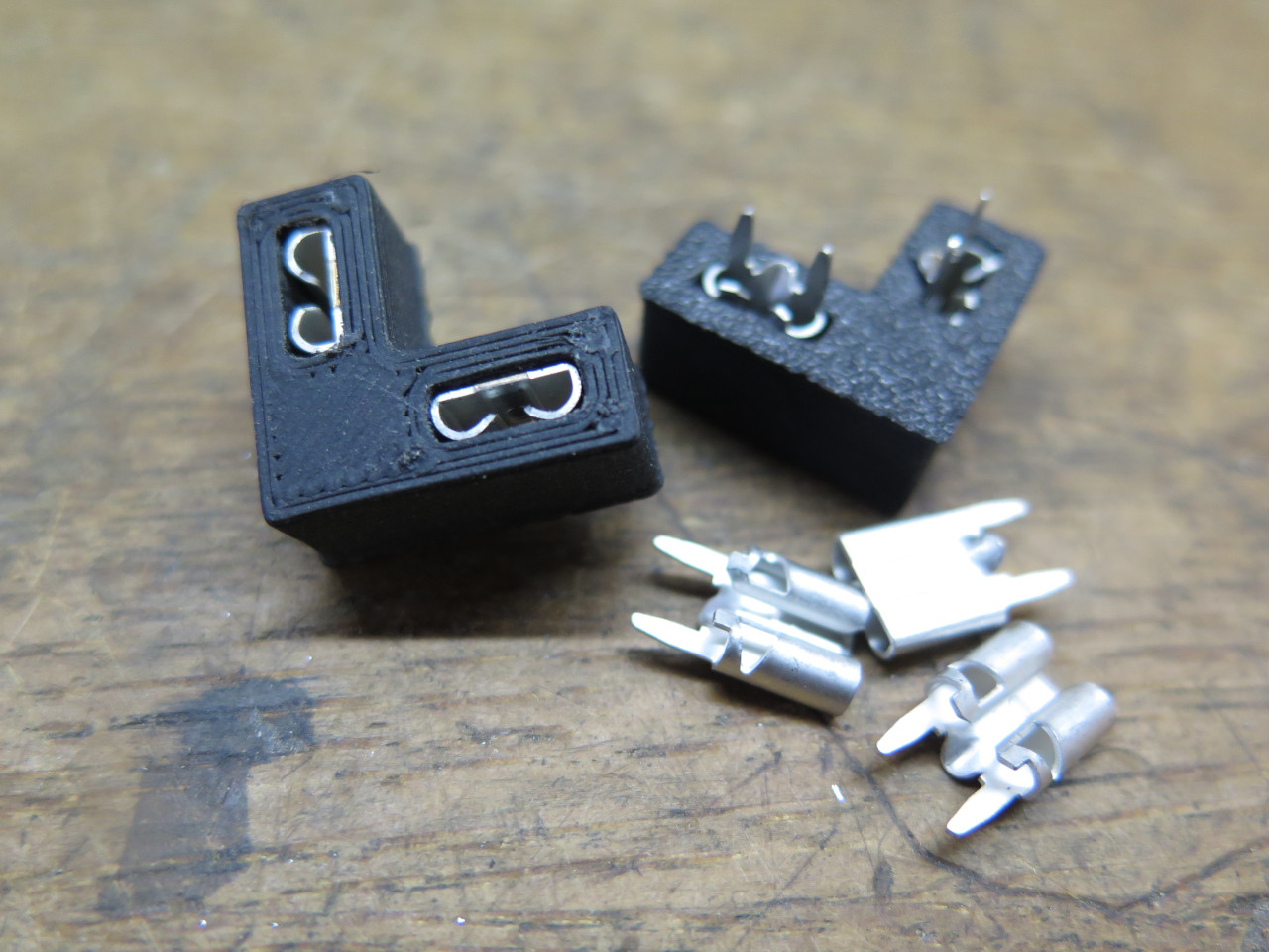
find proper sockets for the two terminal flasher units, so these are
just some female spade terminals in 3D printed housings. The LEDs
are for some simple diagnostics. There is a yellow LED across each
relay coil, and a green one connected to the switched contacts.
When all is normal, both the yellow and green will come on when a relay
is activated.
I also couldn't find a busbar small enough to work, so this one is shop
built. The smaller piece is where the positive battery power comes
in.

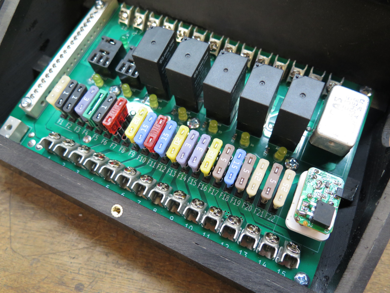
All ready for assembly.

I don't have all of the relays yet, and these are just random
fuses. I still need to determine fuse ratings for each
circuit. Also, the electronic flasher unit I have is too tall, so I
have to run it without its case.
Yay, it fits! Even with the bonnet down! I'm thinking some kind of logo or design on the cover.
This was one of those projects where the planning dominated. Time
spent on the computer far, far exceeded the hands-on building
time. Cost was not insignificant, either. There is probably
$200 in parts alone. Preliminary testing of the unit itself shows
that it works OK.
Comments to Ed at elhollin1@yahoo.com
To my other GT6 pages