To my other GT6 pages
September 16, 2022
Dash Pre-Wire
It's a pretty common opinion that one of the weakest points of British
sports cars of this era was their electrical systems. Most of
these cars develop electrical problems at some point in their
lives. Cheap switches, iffy grounds, barely adequate wire sizes,
and the absolute minimum of fuses and relays gets us a failure prone system.
I stripped the wiring harness out of the car pretty carefully, just in
case I wanted to re-install it. On inspection though, there were a
lot of problems. Frayed and melted wires, brittle or even
breached insulation, and corroded connections all disappointed me.


So, disillusioned with the original harness, I considered my
options. Replacement harnesses are apparently available, but these
don't really solve any of the design problems. Upgraded systems
with additional fuses and relays are also available, and I studied them
pretty closely. They solved some of the issues with the original
design, but didn't really address a common failure point on these
cars: the ground system. Like most cars, these designs use
the body of the car as a ground return path for most loads. This
by itself isn't so bad, but the execution is where the problem
lies. Simple spade lug connections with dissimilar metals,
sometimes in locations that can experience moisture is not a recipe for
success.
And then there was the glaring fact that I had changed the dashboard arrangement, and intended to add several new circuits. Any commercial solution would have to be modified to some extent.
So, after conferring with Inner Engineer, it seemed clear that the best
path for this project was a bespoke wiring system. I'd done this
exactly once before on my TR6, and I adopted the same design philosophy:
• Loads over 5 amps will use a relay.
• Each load or associated group of loads will be on a separate fused circuit.
• No ground returns through the car body.
• As far as possible follow BS-AU7 Vehicle Wiring Color Code, as the OEM did.
• Size wire for current at least 10% above that in ampacity tables.
• Relays and fuses will be located together in an easily accessible place.
I drew up an overall block diagram, identified all of the circuits, and sketched out each circuit.
I had a fair amount of wire left from the TR6 project, and I was able to
salvage a little from the old harness, but still had to order some.

The first part of the system to be done is the dashboard.
The GT6 dashboard is in three sections, but only the left and center
sections have any wiring. I envisioned the dash sections to be
modular: I wanted to be able to remove a few fasteners, pull the
dash section out, then unplug a few connectors, and remove it, complete
with most of its wiring.
So, here we go. Center dash first.

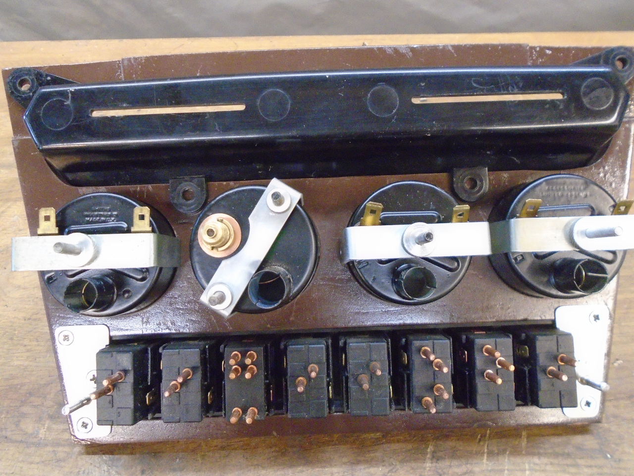
Drawing up a schematic of the center dash, it became obvious that there
were a lot of things that needed a ground return. The factory
handled this by daisy-chaining and by having multiple ground wires
soldered together in the harness. I was looking for something a
little cleaner and repair-friendly. There isn't much bare real
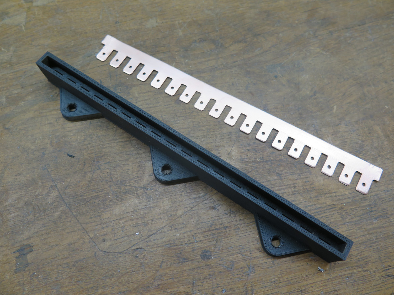
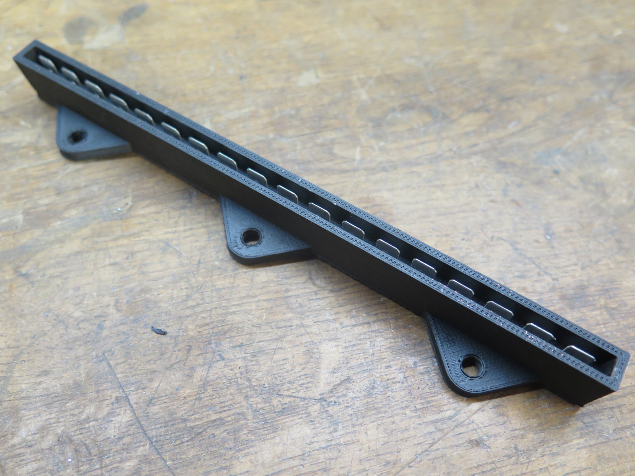
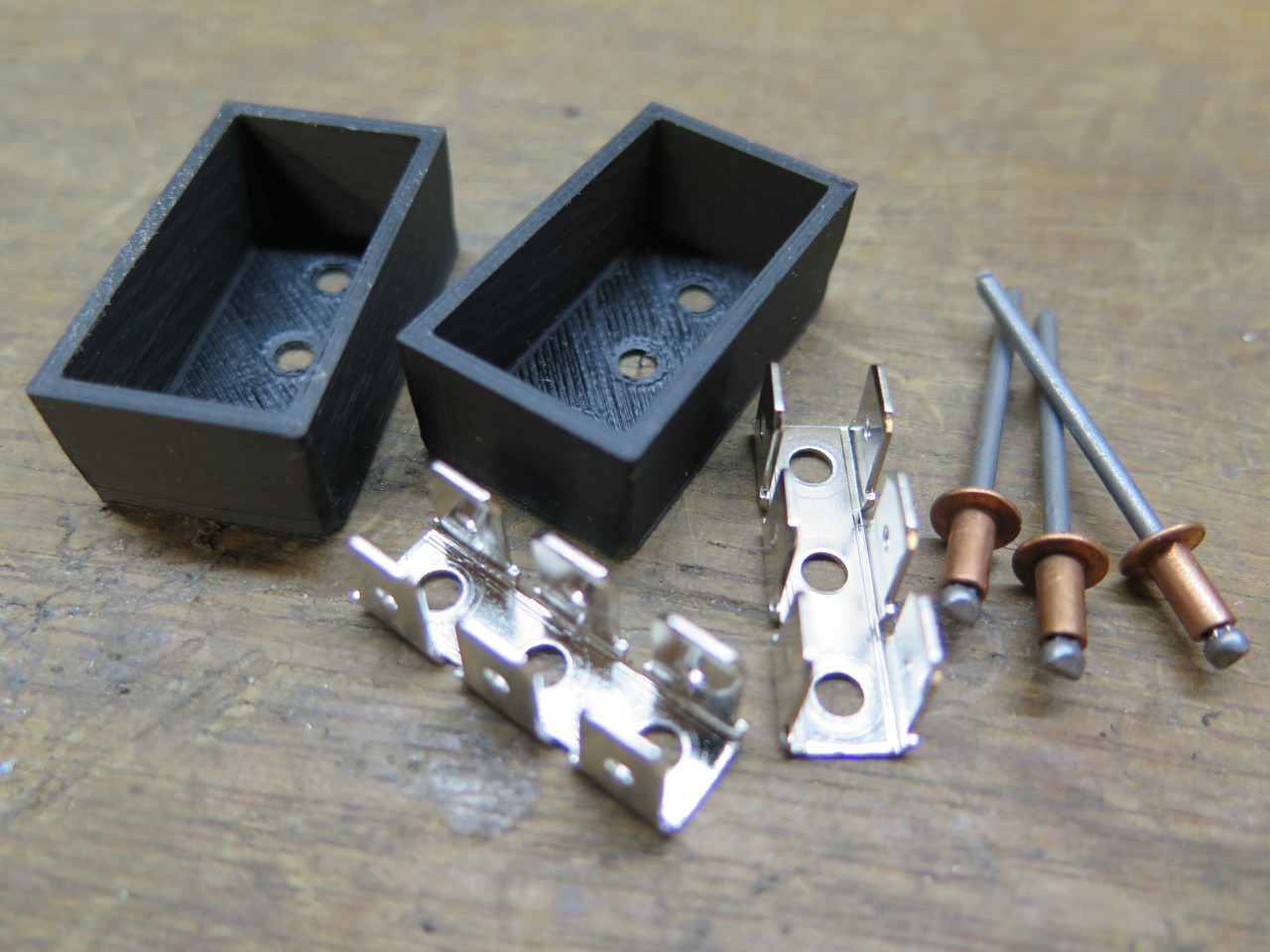
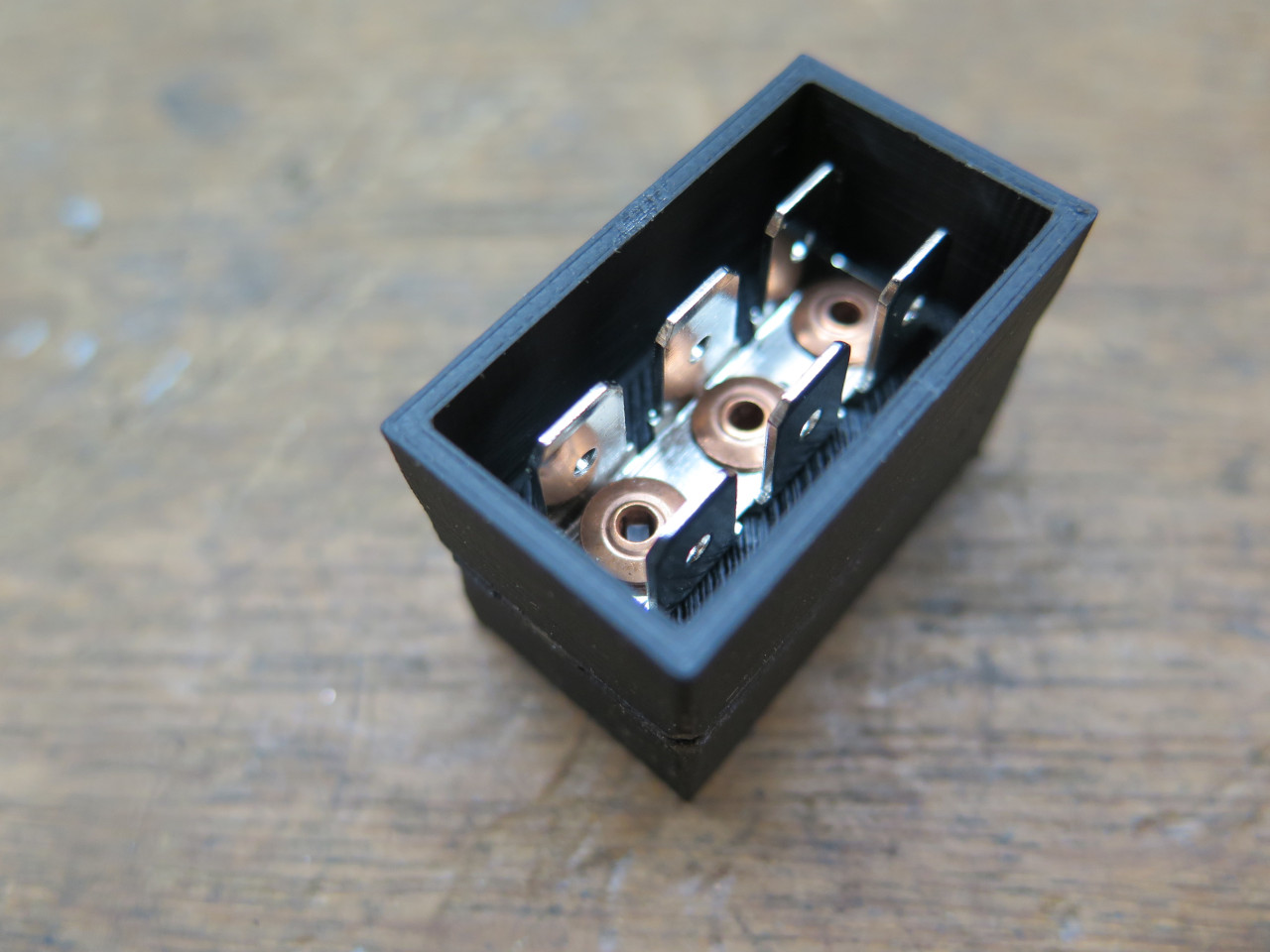
estate left on the back of this panel, but this ground bus fits. A
3D printed housing holds a long copper conductor with 18 positions for
spade connectors. I used them all. And there is a single ground return wire from the center dash.
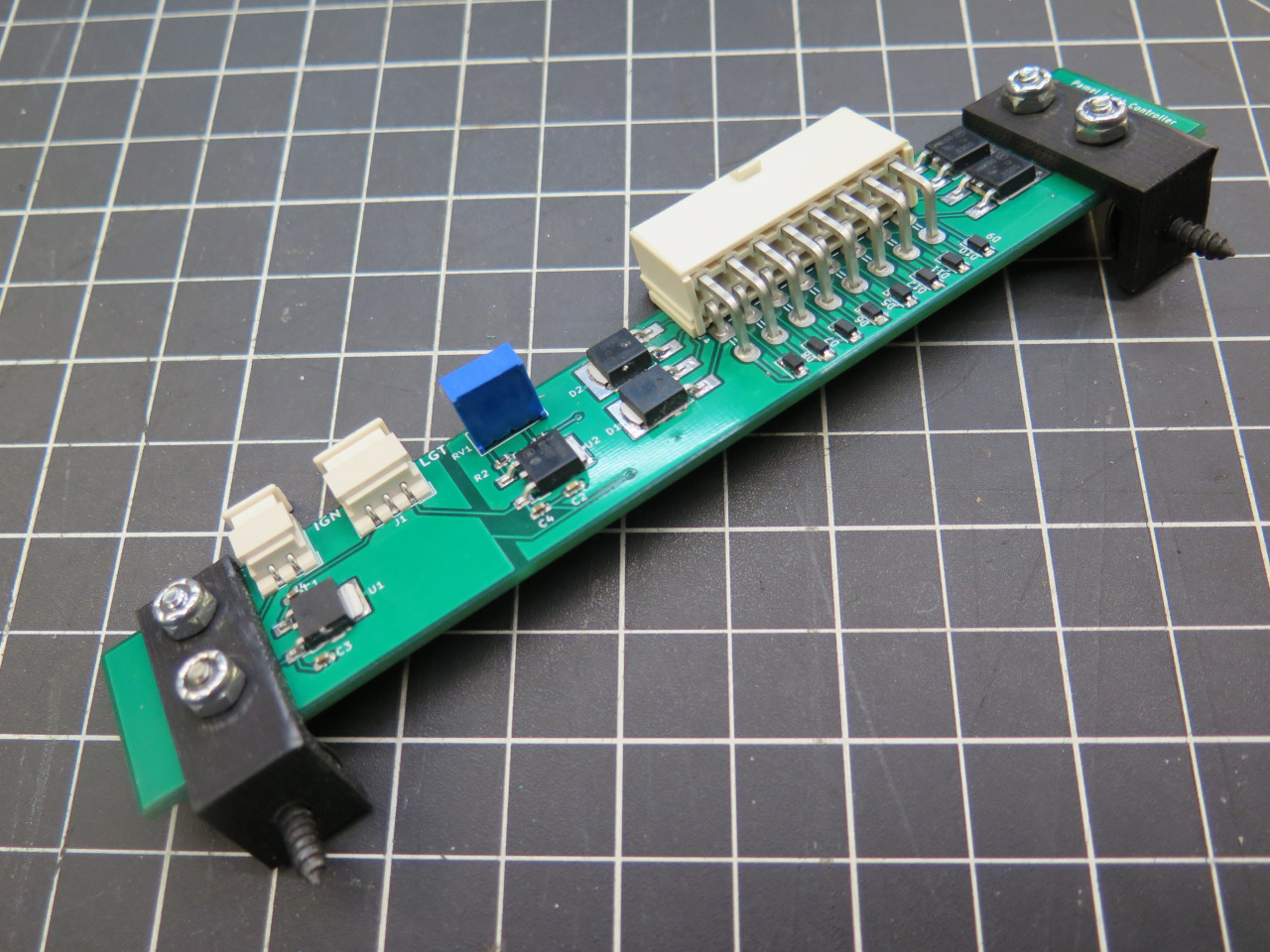
The switches I used are illuminated. I really wanted the switches
to be lit to half brightness at night when the headlights are on, to
make them easier to find in the dark. The light would go to full
brightness when the switch was activated. I became sort of
obsessed with that functionality to the point that I made up a little
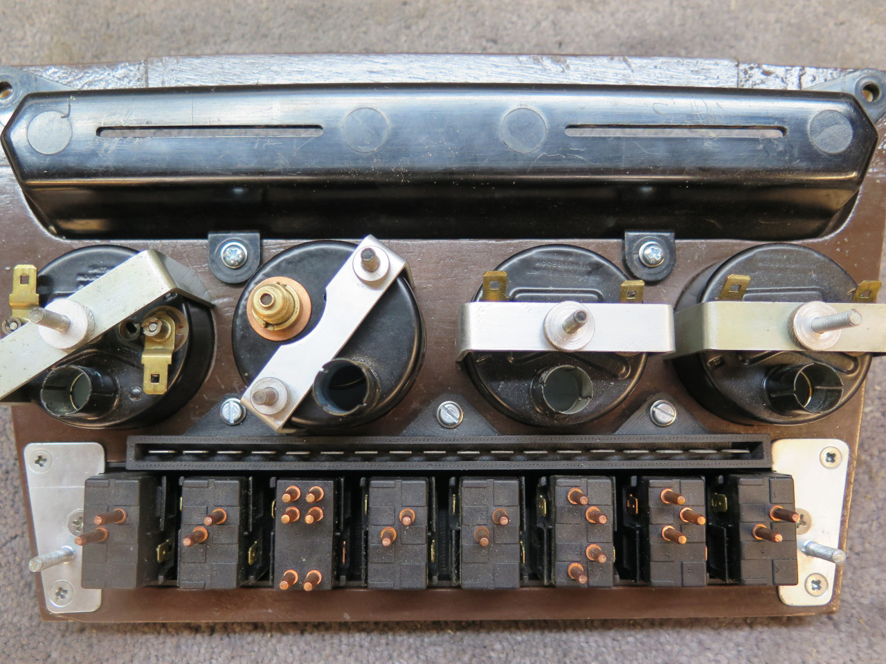
circuit board to accomplish it. It seemed to make sense to also
put a solid state voltage stabilizer for the fuel and temp gauges on he
PCB. The second pic shows the light
controller and the ground bus installed.

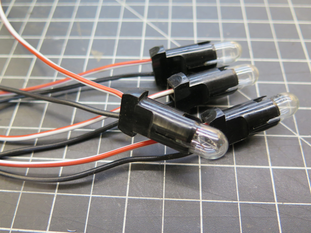
Each of the gauges has an illumination lamp. Because I wanted
lamps with explicit ground conductors, I used these replacement holders.
First thing to get wired up was the illumination circuit. That
black box in the middle is another multiple connection point housed in a
3D printed housing.
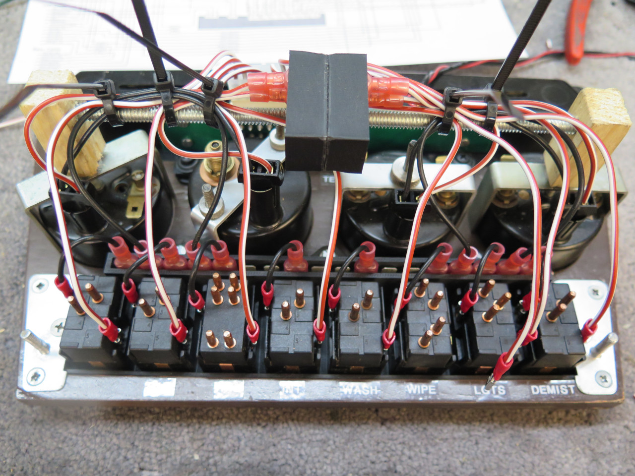
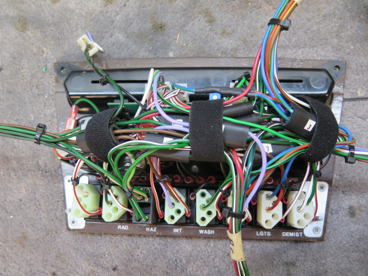
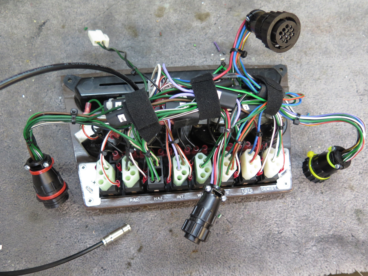
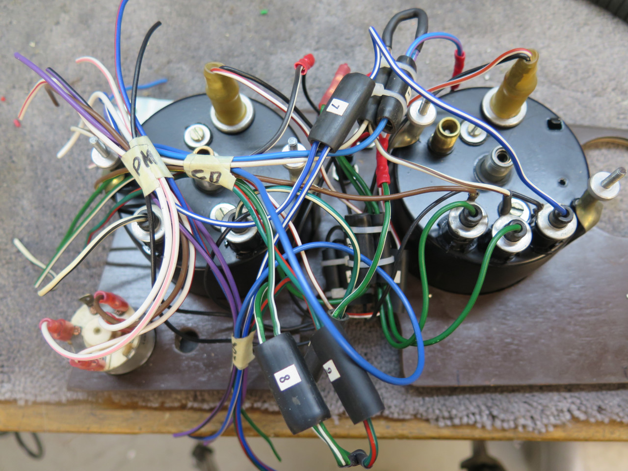
With the rest of the circuits wired. The Velcro bands hold
everything together, but when removed, the wiring can spread out to be
more accessible.
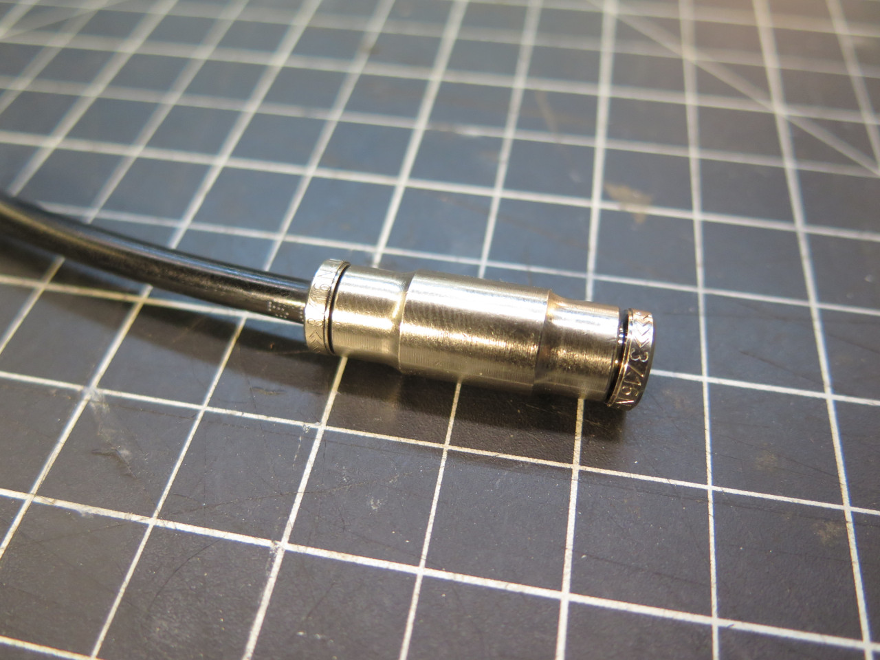
The only other connection to the center dash is the tube for the
mechanical oil pressure gauge. It would sort of defeat the purpose of
all of those electrical connectors if that tube remained connected.
This is a little tubing quick disconnect for the 3/16" oil gauge tube. It works like those Sharkbite
connectors for plastic house plumbing. I haven't tried it, but it's
supposed to be good to 230 PSI.
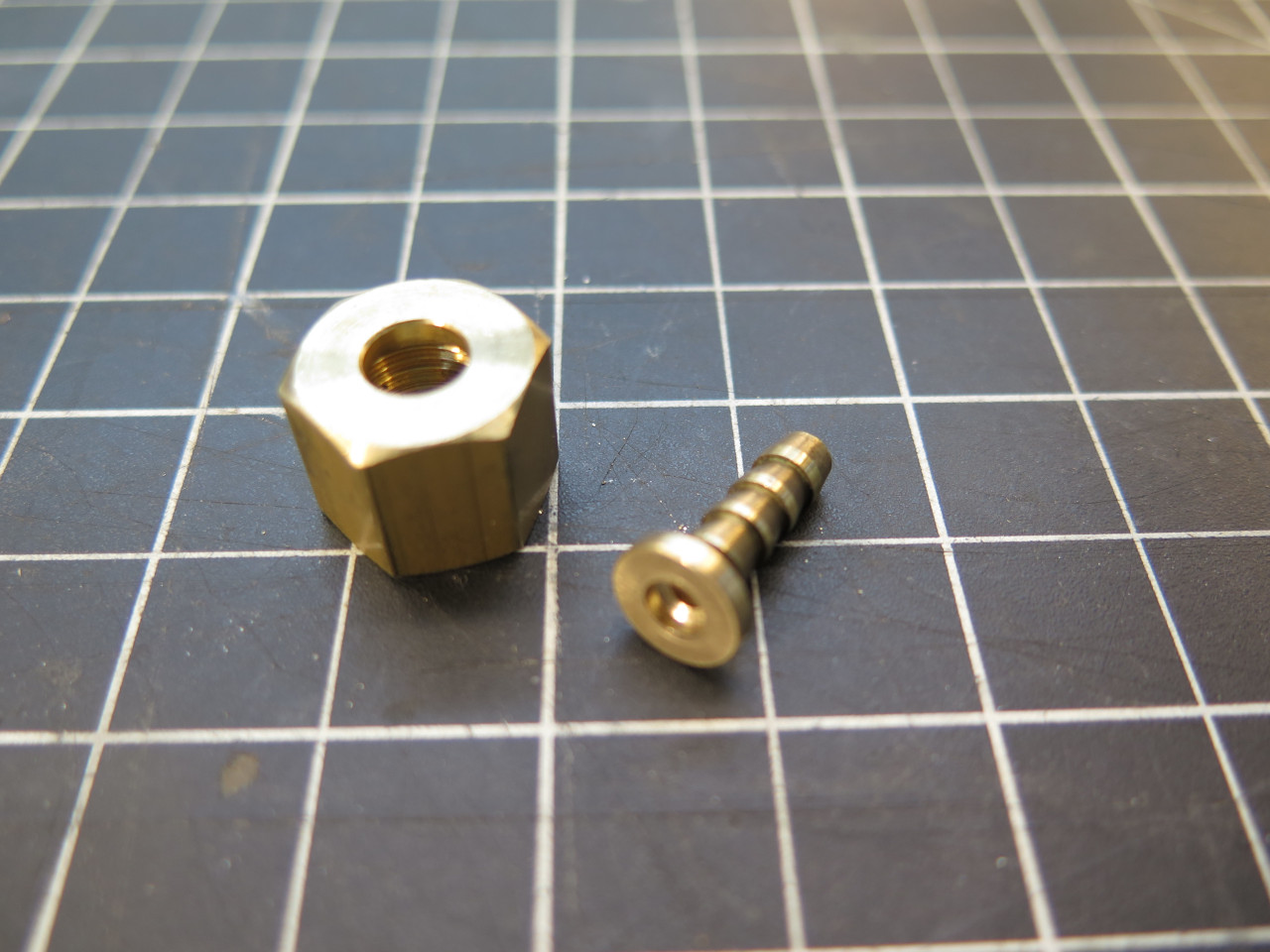
At first, I planned to buy a commercial oil pressure tube and cut it for
the disconnect. But since those tubes seem a little overpriced to
me, I decided to try to make one. I bought some 3/16 nylon
tubing, and the little
nut that screws on the back of the gauge. It's a BSP thread, not
that
common in the US. This one was for a Mini. The other part
was
machined from a standard hose barb fitting.
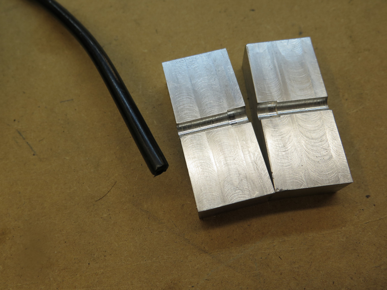
The hardest part of the oil tube job was persuading the nylon tubing to
go on to that hose barb. The tubing is very tough and stiff, and I could not push it on without it kinking.
The answer was to make a split block clamp to tightly hold the tube while the
barb was pressed in.


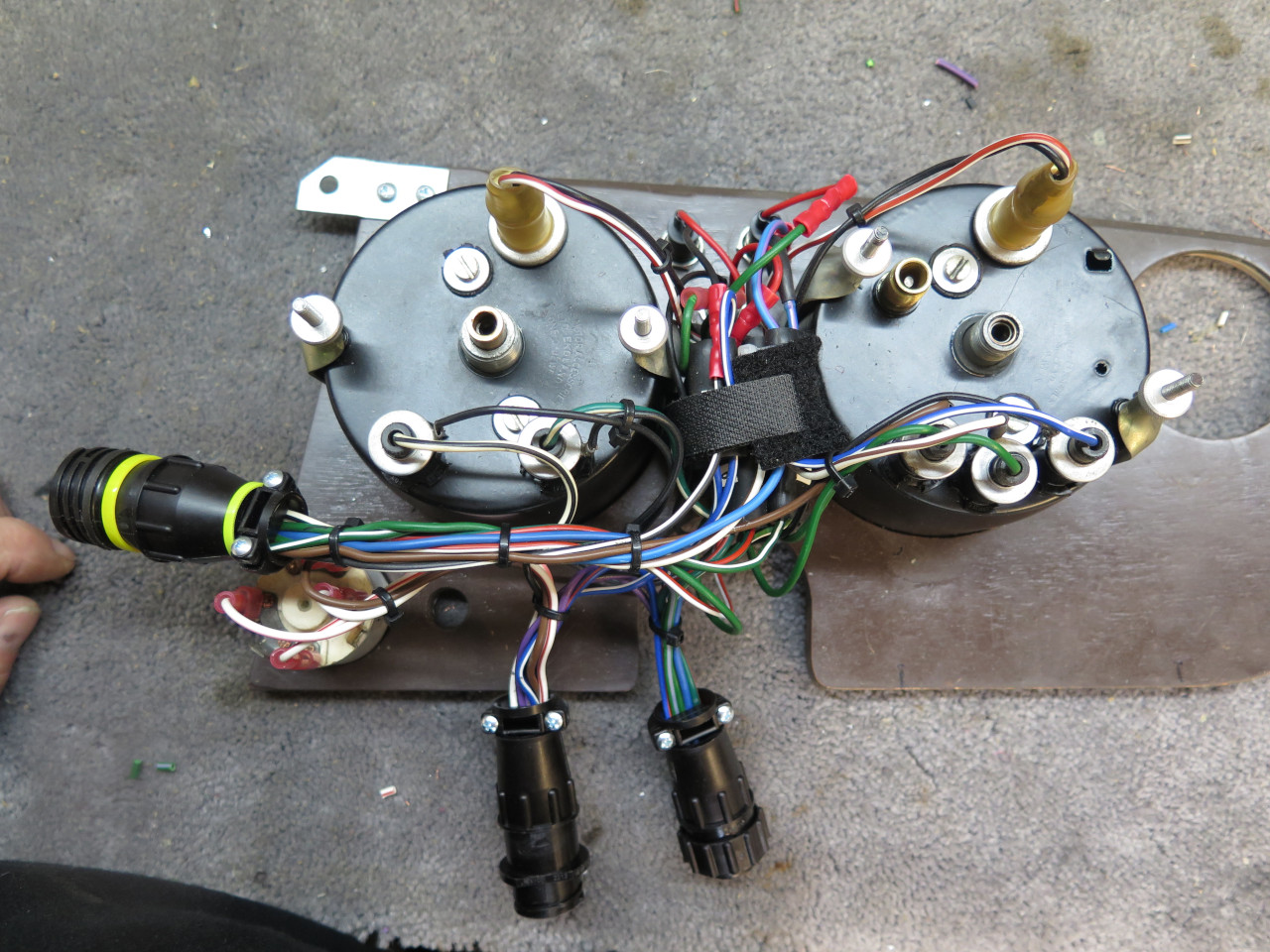
Then the electrical connectors were applied. There are five electrical
connectors for the center dash: Clockwise from right: Connector to
left dash; Connector to cable to the rear of the car; Connector to the
Power Module (Fuses and Relays); 2-pin connector for the heater fan;
Connector to cable to the front of the car.
Then, on to the left dash. The left dash isn't changed as much as
the center dash. The windscreen wash/wipe switch function is moved
to the center dash, and the hazard switch, also moved to the center
dash, is replaced by three indicator lights: parking brake, brake fail,
and turn signals.

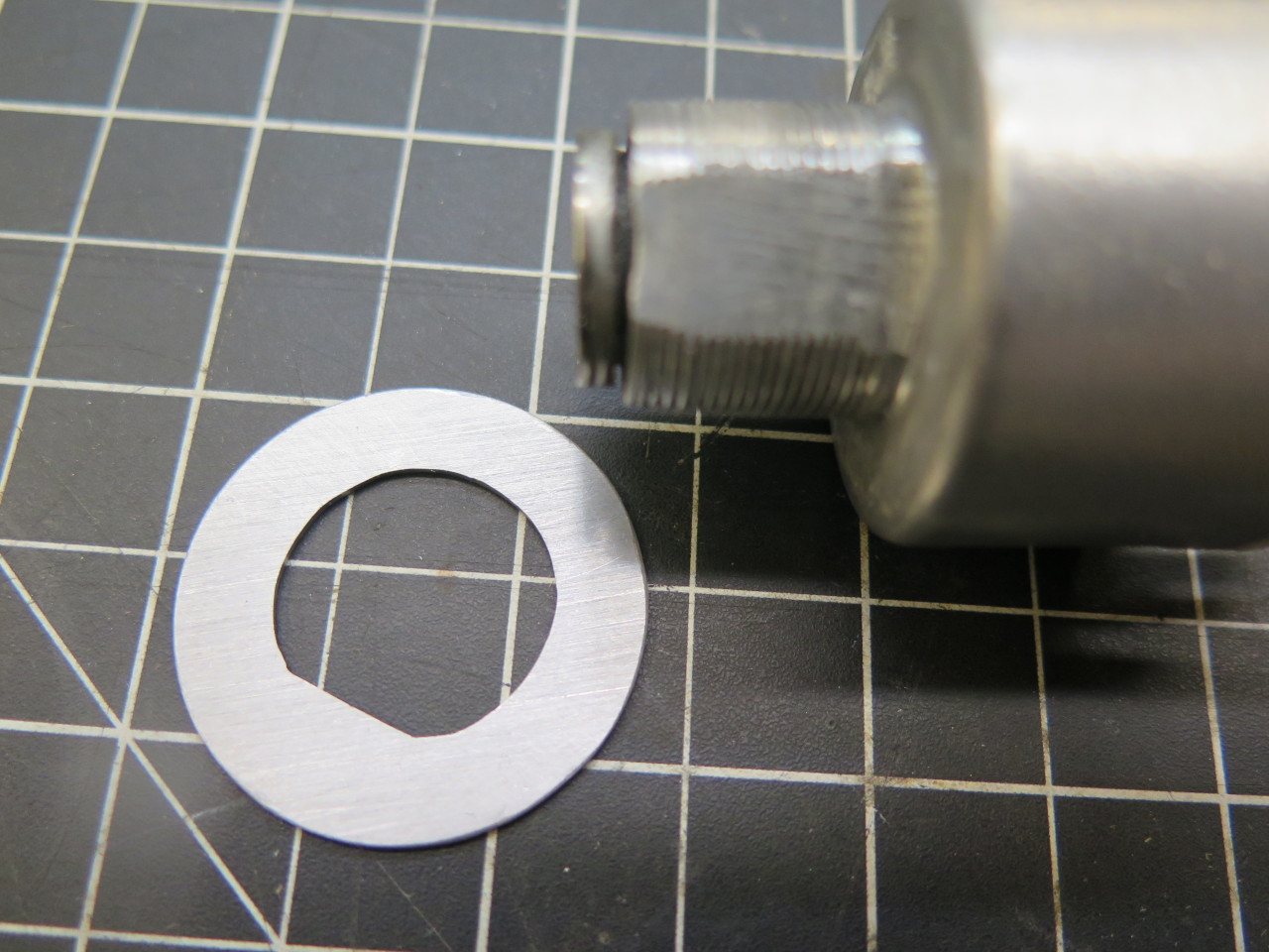
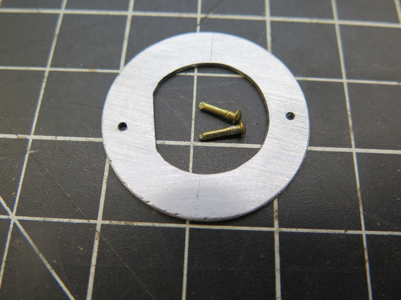
One little thing to take care of before I started the wiring was to
secure the ignition switch against rotation. The switch shank is a
"D" shape, but the dash hole is round. This little metal insert
is epoxied into a recess on the backside of the dash.

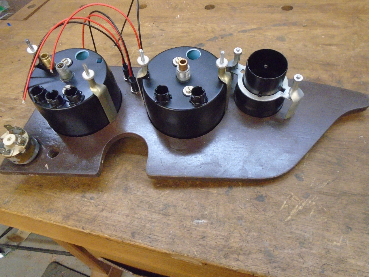
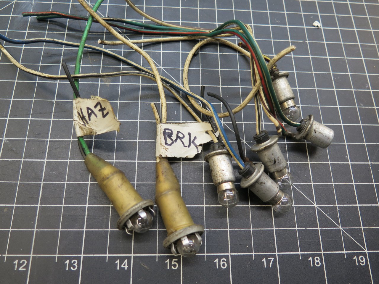
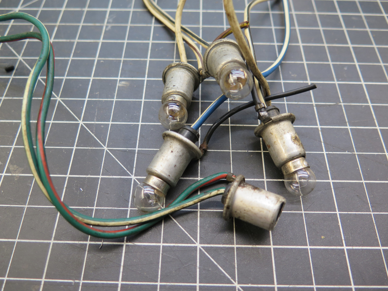
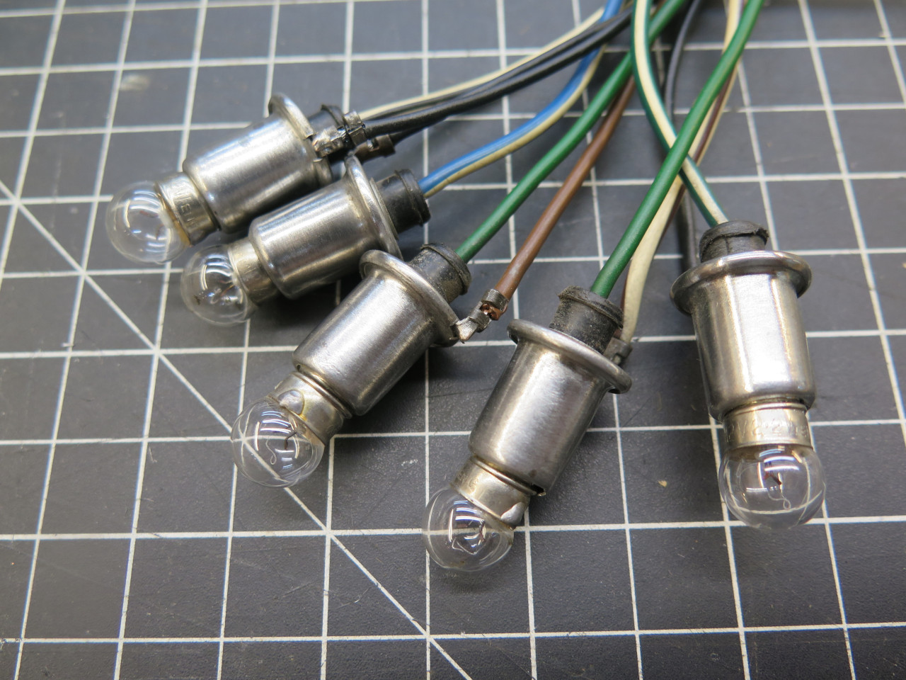
Then there were the lamps. Each of the instruments (speedo and
tach) has an illumination lamp, and a total of five indicator lamps:
demist, oil pressure, ignition, hi beam, and turn signal. The
original illumination lights were only single wire, but I wanted
two-wire sockets so as to have an explicit ground. Since the
original hazard and brake warning lights were the same size, but
two-wire, I re-purposed them.
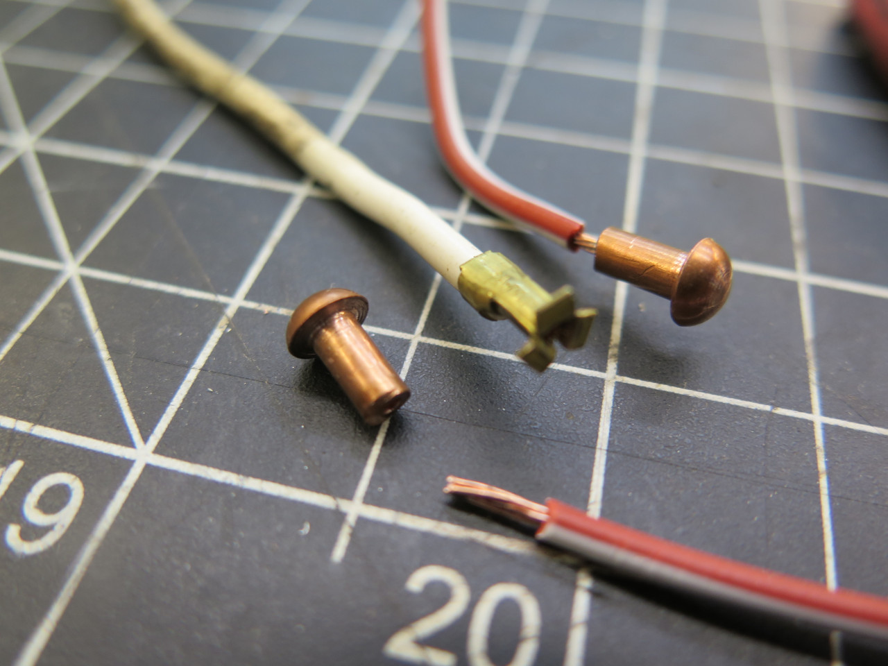
The wire colors were wrong though, and some of them were too
short. The center hot wire in the sockets just went to a little
splayed brass thingy to contact the lamp. I replaced those
contacts with small copper solid rivets with a hole drilled in the shank
to receive a new wire of the proper color. The wire to the outer
shell was also replaced with a black wire.
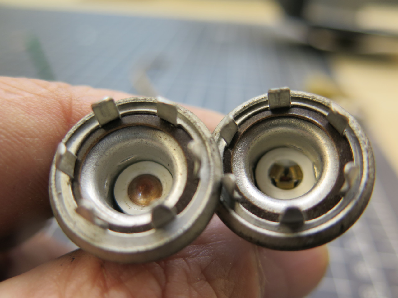

A similar process got the smaller indicator lamps ready for install.
Right now, all of these lights are still incandescent. I may go to
LEDs for these, but the advantages of LEDs for these small loads are
limited.
Running the rest of the of the wiring creates sort of a rats nest, but
before I neatened it up, I installed the connectors. Appropriate
terminals are crimped to each wire, then the terminals are installed
into the circular connector housing.
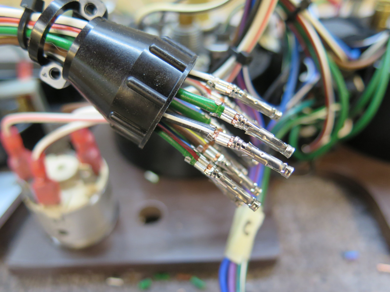
The left dash has three circular connectors: one to the center dash, one
to the Power Module, and one for the steering column. Most of the
wires are tucked between the instruments, but pull out easily for
better access.
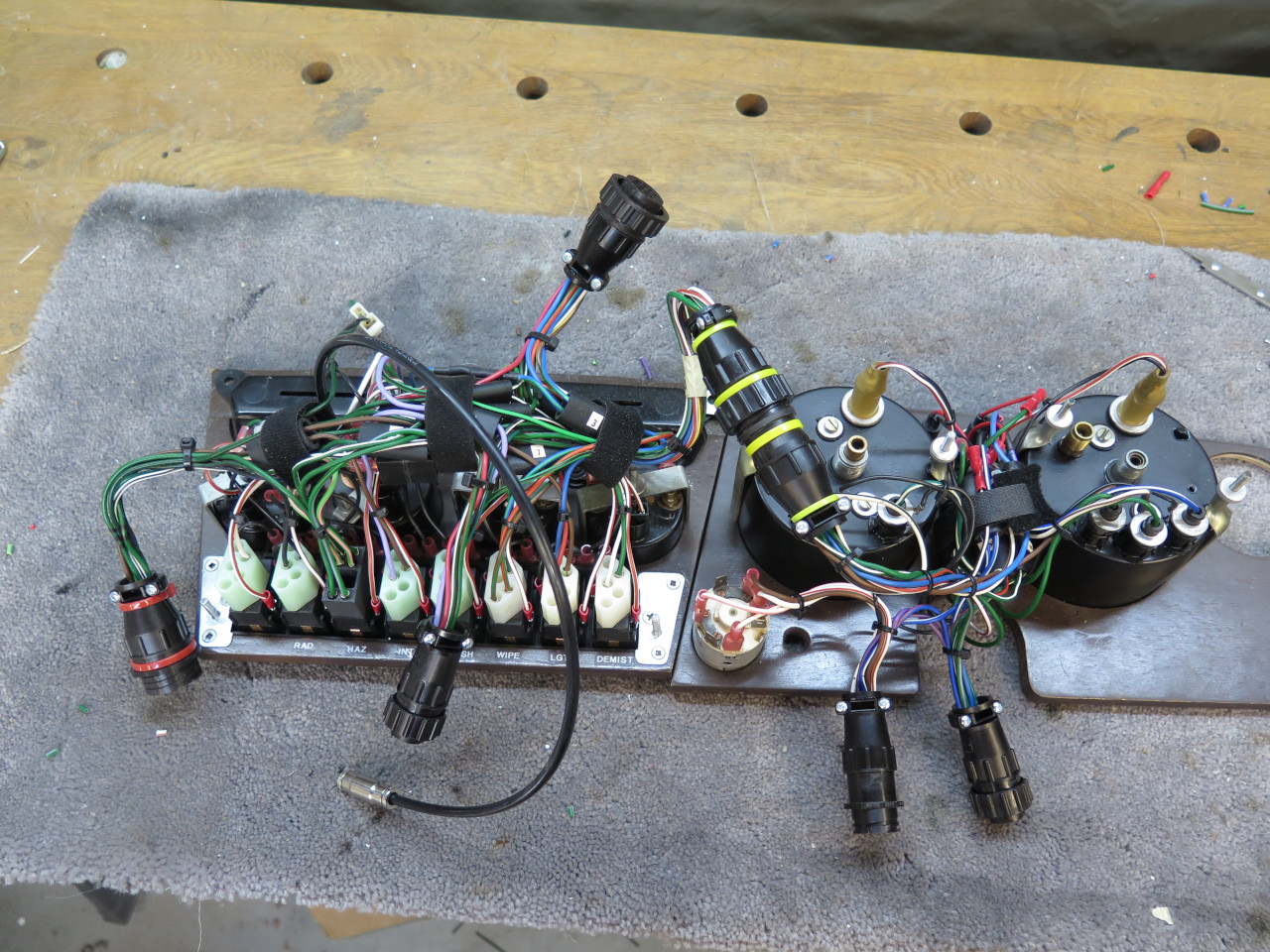
The rear of the dash, showing the left dash/center dash
connection. The connectors were chosen to be different sizes and
genders, so it shouldn't be possible to plug something in wrong.
This is one of those projects where the design and planning took a lot
longer than the execution. It wasn't cheap, either. Just the
connectors were close to $100.
Comments to Ed at elhollin1@yahoo.com.
To my other GT6 pages