To my other GT6
pages
March 20, 2021
Hand Brake Lever
I am prone to forget to release the parking brake before
driving. I don't think I've ever caused any major damage by
doing this, but it certainly isn't good for the brakes. On
my more modern cars, I rely on warning lights or audio to tell me
when I've spaced off the brake. I believe some later
Triumphs did have a warning light on the dash, but this GT6 had no
such amenity. Since I'd had the forethought to include a
Parking Brake warning light on the fancy new dash,
I had to follow through and provide a sensor to go with the light.
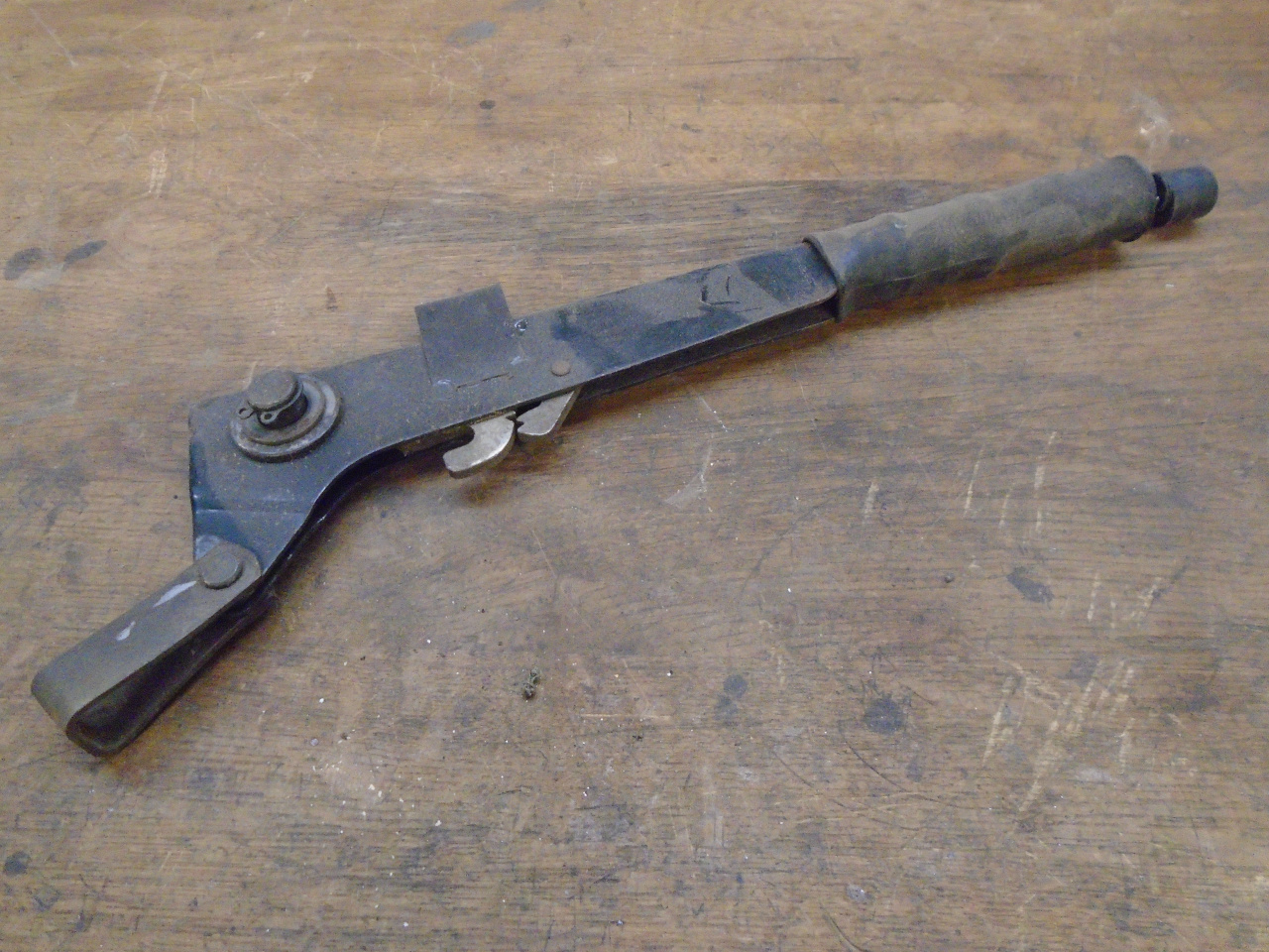
On the GT6 and related cars of the era, it was common for the
parking brake to be actuated by a hand lever next to the driver's
seat. Pulling up onthe lever pulls a cable that in turn
applies the rear brakes. The lever includes a spring loaded
pawl/ratchet arrangement such that the lever holds position when
pulled up tight. A button on the end of the lever disengages
the pawl to release the brake. The lever provides a
mechanical advantage of about 4.5:1.
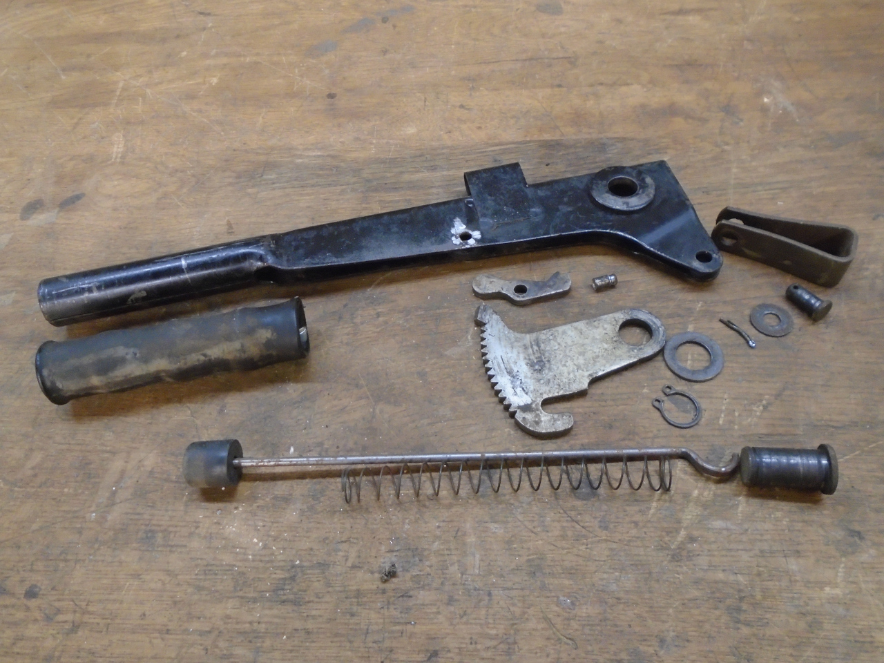
My lever was cruddy...

...but it came apart pretty easily.
My plan was to install a snap action switch (often called a
"microswitch", but that's actually a brand name) on the lever that
signals when the lever has left it's fully down, released
position. My first thought was a mercury switch that detects
tilt. As I thought about the effects of the grade where the
car is parked, and G forces while driving, I decided a more
conventional mechanical switch might be better.
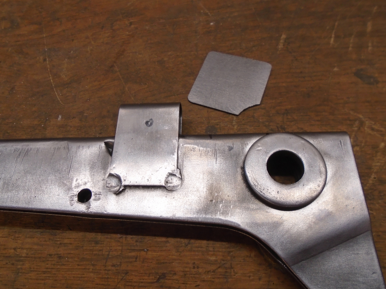
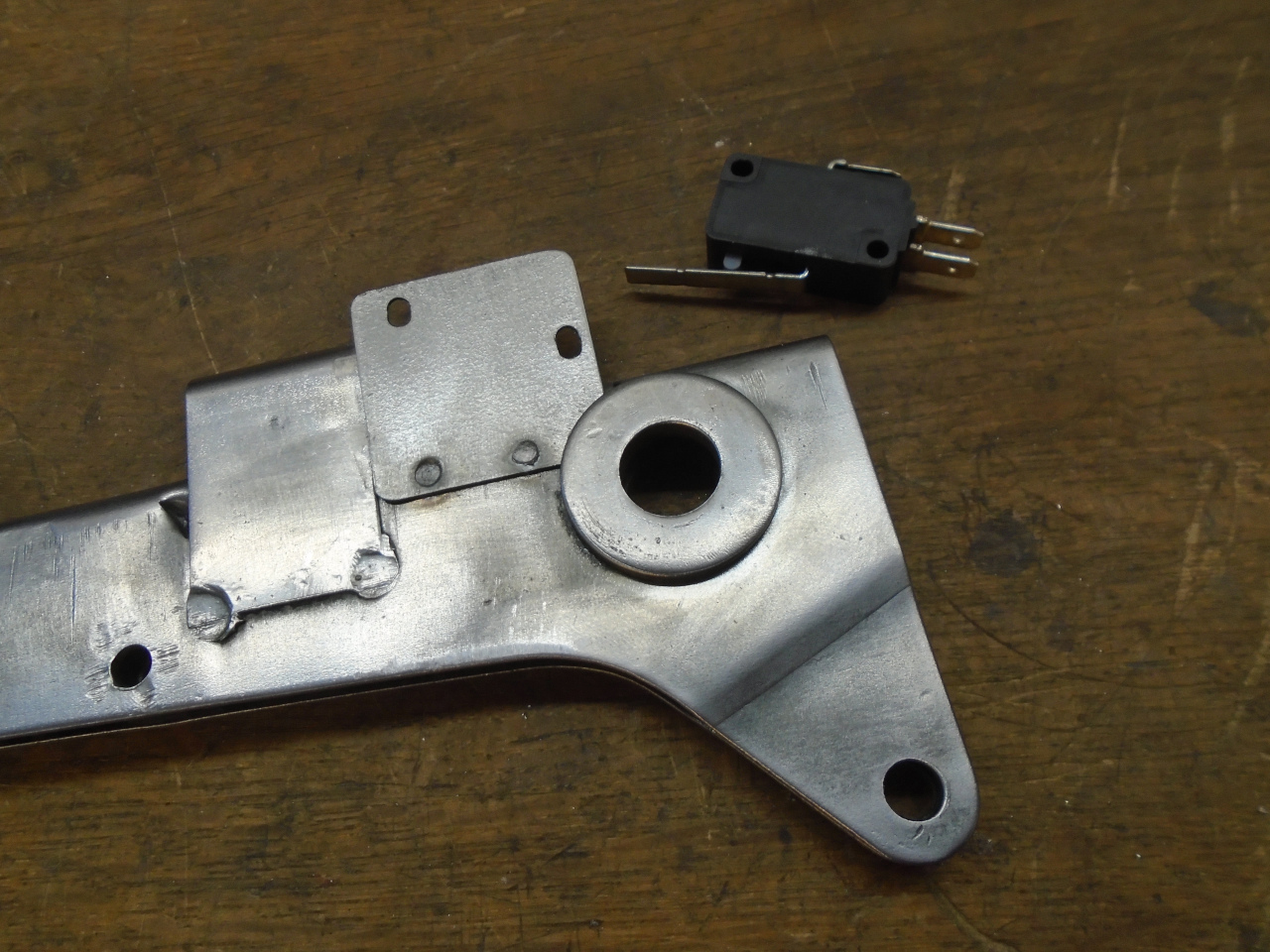
There didn't appear to be a natural place to put the switch, so I
had to do a couple of tweaks. There is a slot on the top
spine of the lever that the toothed ratchet segment pokes through
when the brake is released. I thought I could somehow
activate the switch with the ratchet. I extended the slot to
provide better access to the top of the ratchet.

But even then, the ratchet was too far down in the hole for the
switch to reach. I decided to add a little nub to the
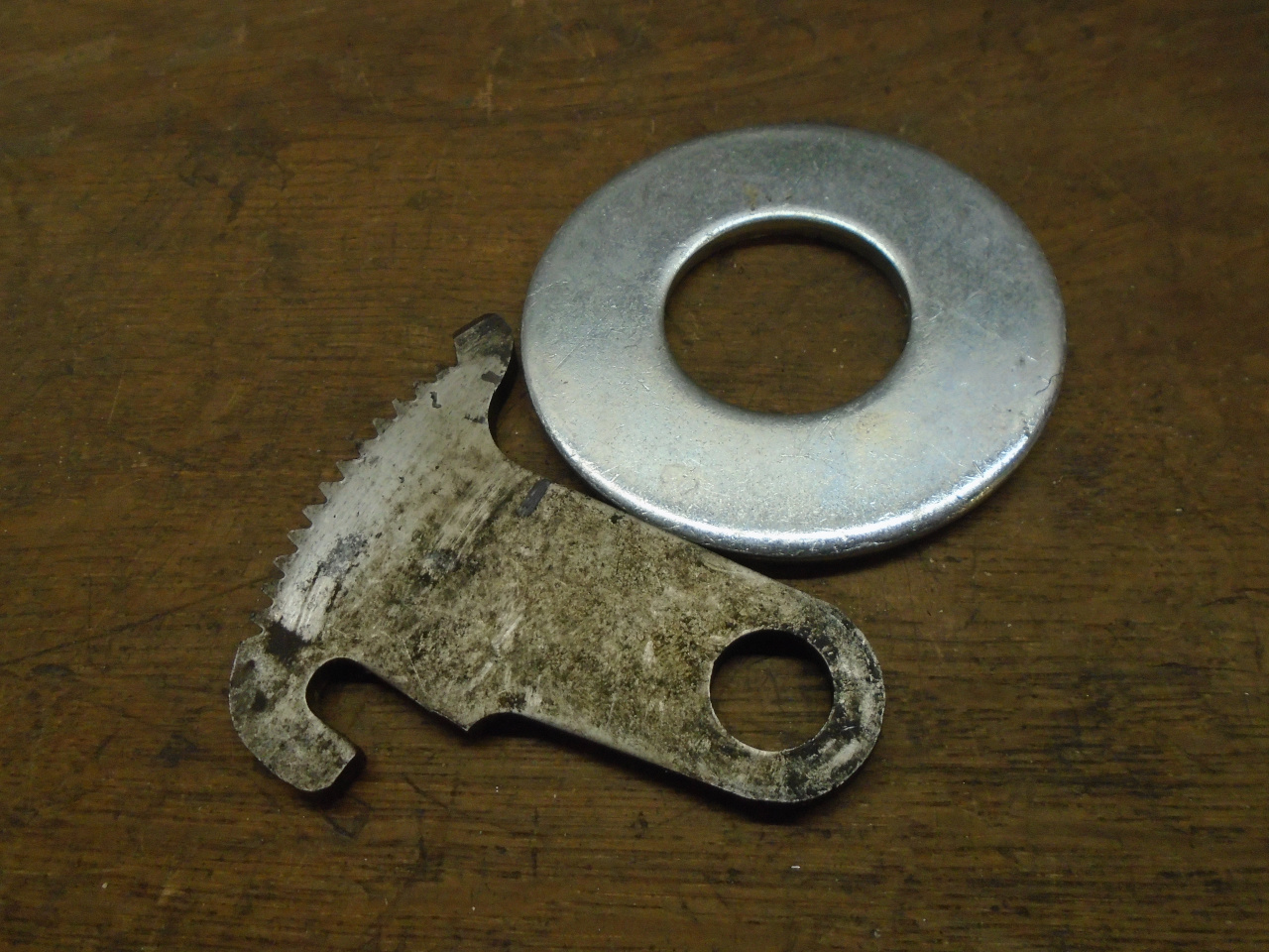
ratchet to poke up through the slot. The thickness of the
ratchet was about 0.160" (likely 4 mm, actually). I found a
big washer very close to the same thickness.
I cut a contour to match where it would be joined to the ratchet,
and left it long elsewhere to help with holding and
clamping. The ratchet material is very hard, so I
tried to limit the heat from welding to preserve the temper.
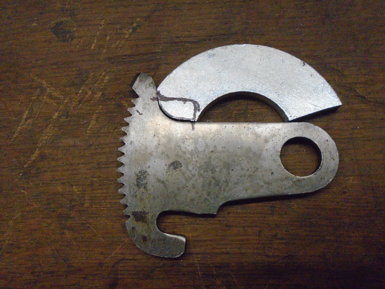
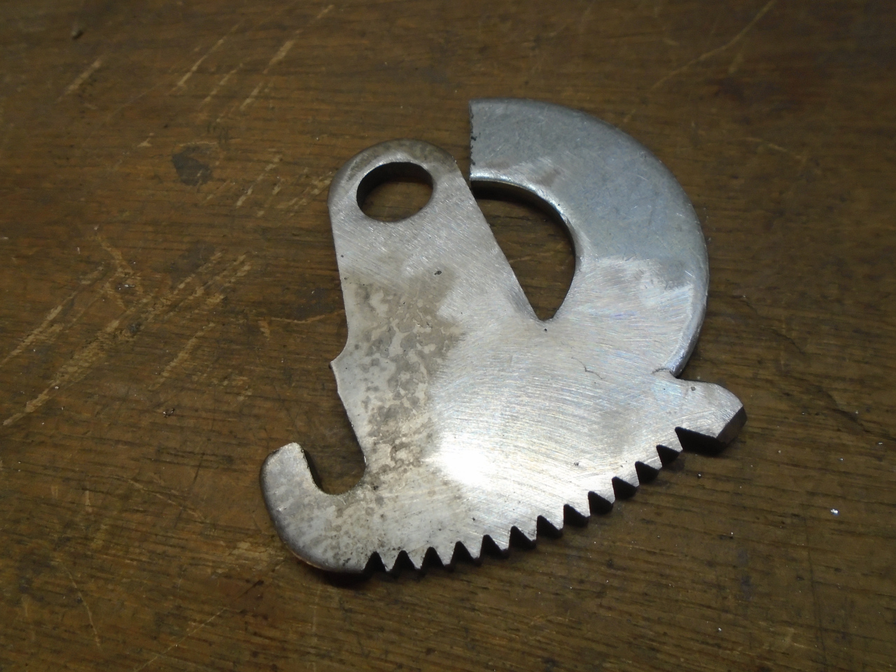
Then trimmed to shape.

Then I had something to work with.

The switch would be located on the spine of the lever, with its
actuator over the new slot. A little plate would be attached
to the side of the lever to mount the switch.
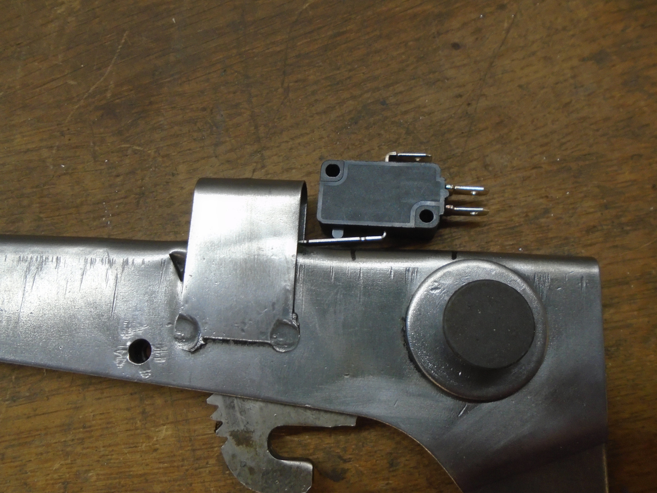
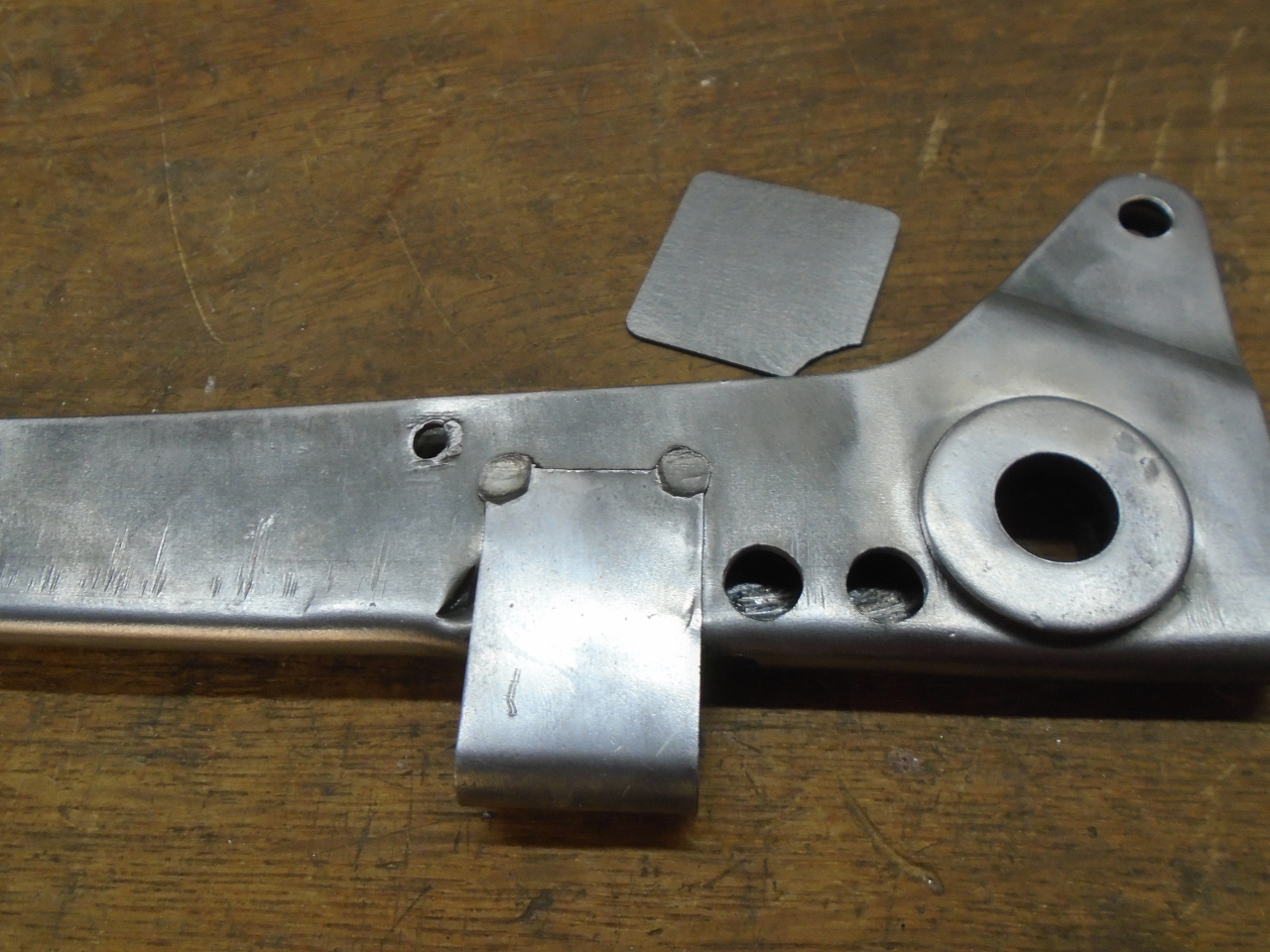
I thought spot welding was the cleanest way to attach the switch
mounting plate, but the double wall of the lever wouldn't permit
that. At least not until I drilled a couple of holes on the
opposite side for spot welder electrode access.
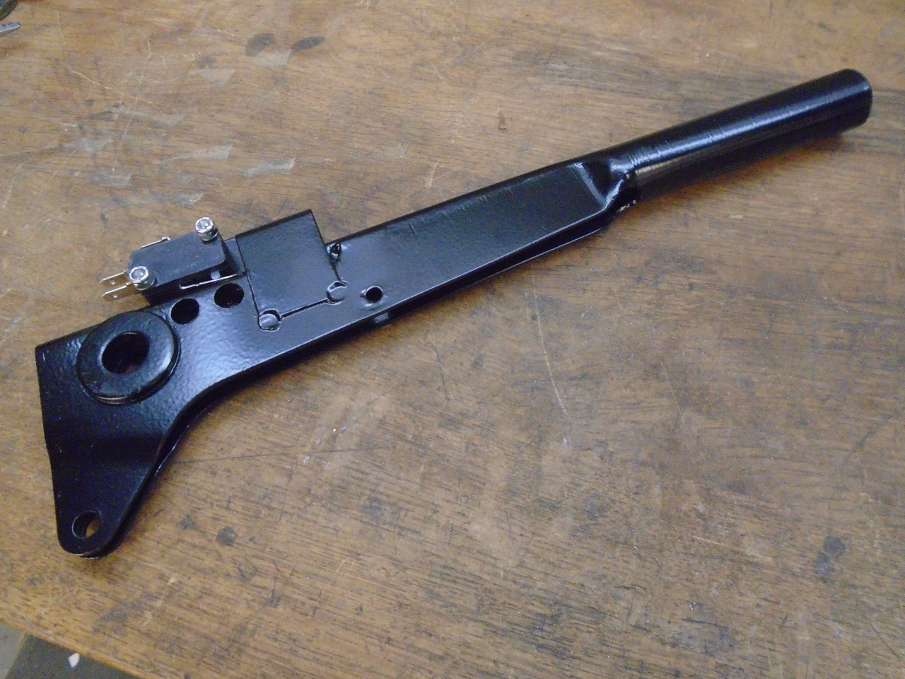
Then mounted the switch.


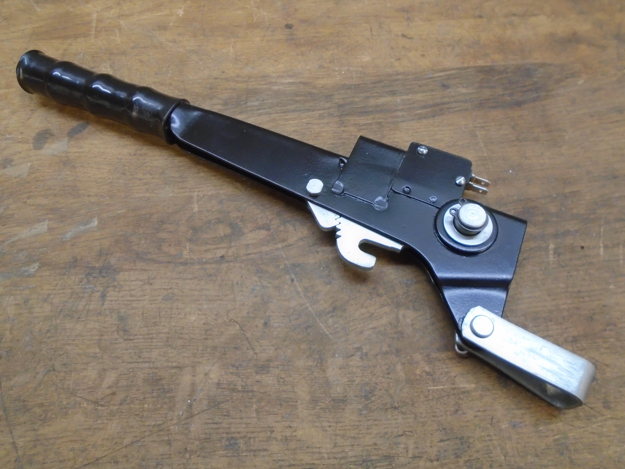
The switch/ratchet seemed to work OK, so I powder coated the lever
body.

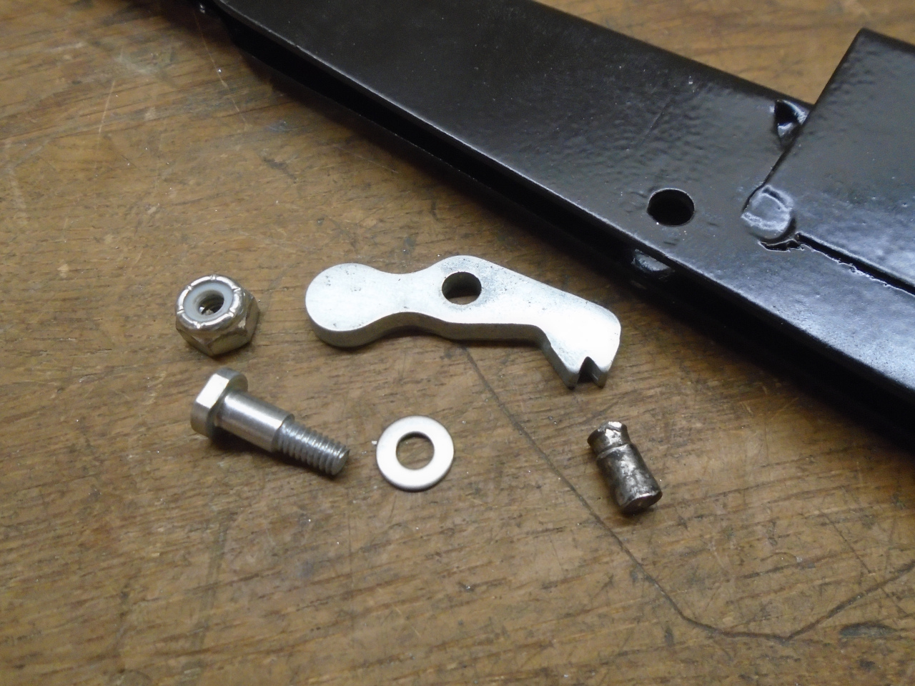
Before reassembly, the pawl assembly needed some attention.
The pawl was originally held in place by a simple pin (on the
right in the picture) that was apparently just peened on both
sides to keep it in place. Instead, I used a shoulder
bolt. Since the hole in the pawl is an odd size (well, odd
on this side of the pond--I think it was 5 mm), and the pawl is
too hard to drill easily, I just made the shoulder bolt to fit.
Gathered up all the cleaned up parts...
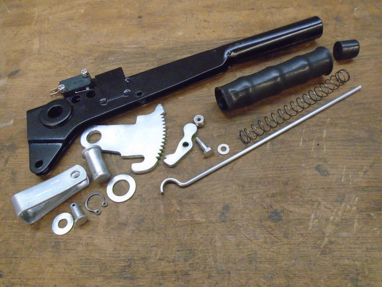
...and slapped her together.

This was one of those quick, silly little tasks that might only
take a few hours of actual time, but adds something worthwhile to
the overall project. Cost was a few bucks for the switch,
plus some consumables.
Comments to Ed at elhollin1@yahoo.com
To my other GT6
pages