To my other TR6 pages.
October 26, 2018
Final Engine Bay Work
I
think I'm seeing the home stretch on this project. On a path
to the first startup, there are a few things to wrap up in the engine
bay. After some routine things like connecting the throttle
linkage, choke cables and oil gauge line, a few others took some more thought.
Alternator Bracket
The
stock arrangement for setting fan belt tension was by one of those
dog-leg brackets on the alternator. The one on the TR6 was kind
of thin and wimpy.
It's
a small thing, but I never liked the looks of those. They seem to
be sort of a generic, universal fit item. I thought something
more fitted would look better. Also, I never liked the fact that
one of the water pump fasteners had to be loosened to free the
alternator bracket. Once a gasketed joint is closed, I don't like
to disturb the fasteners.
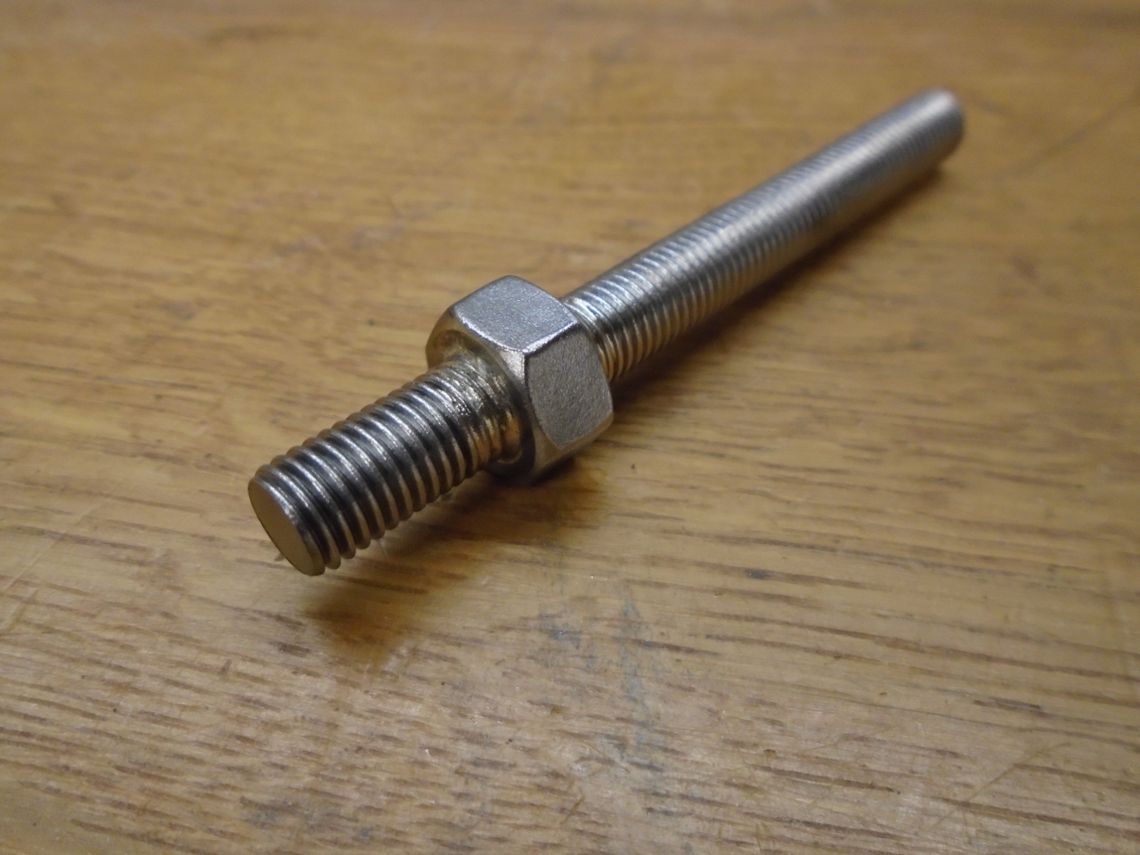
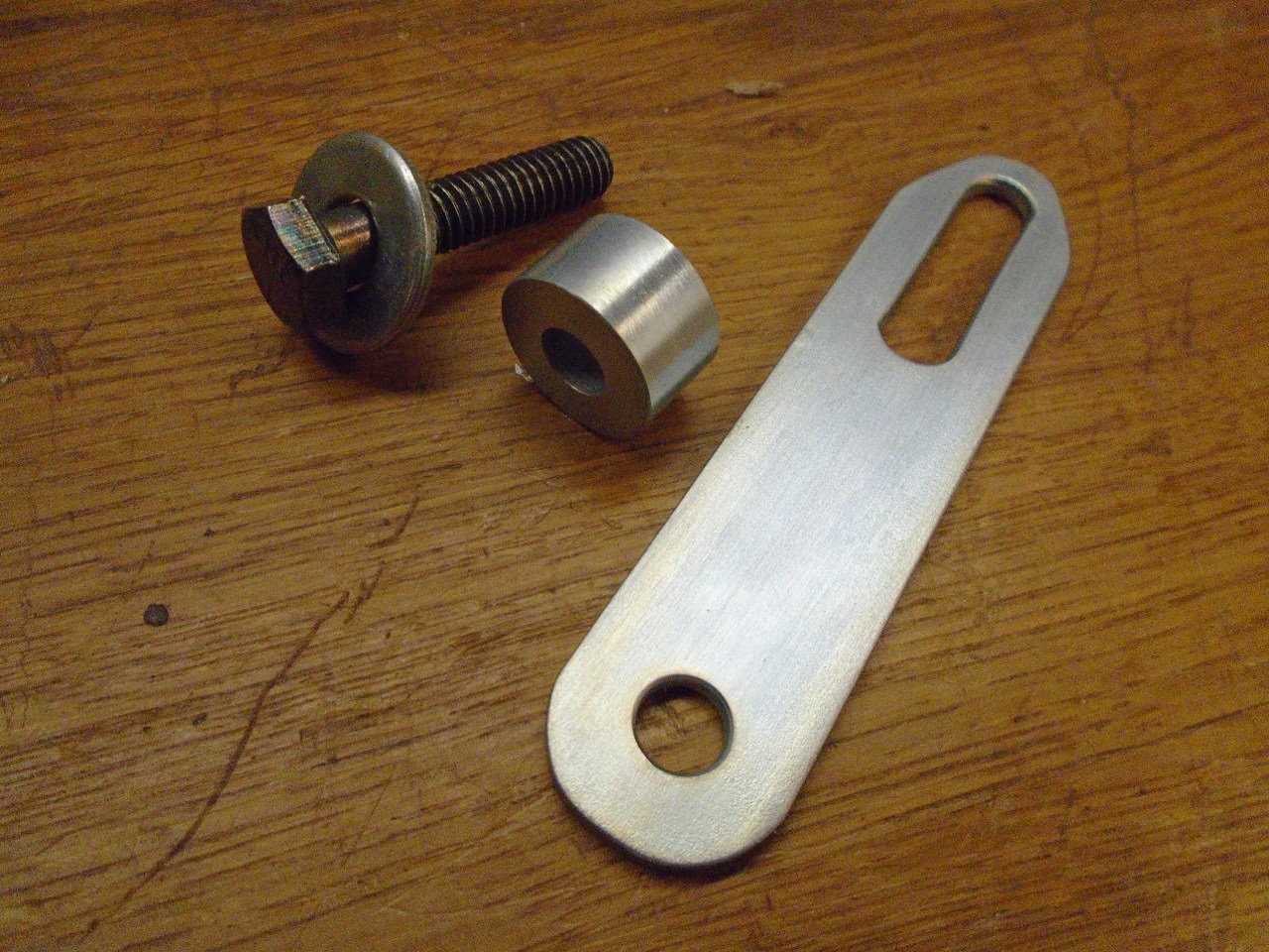
To
make me feel better about it, first, I made a new water pump fastener.
Sometimes called a "hex stud", it has a hex shape part way down a
threaded stud. I made it by silver brazing a nut onto a short
threaded rod. Once installed, it provides a stud for the alternator bracket.
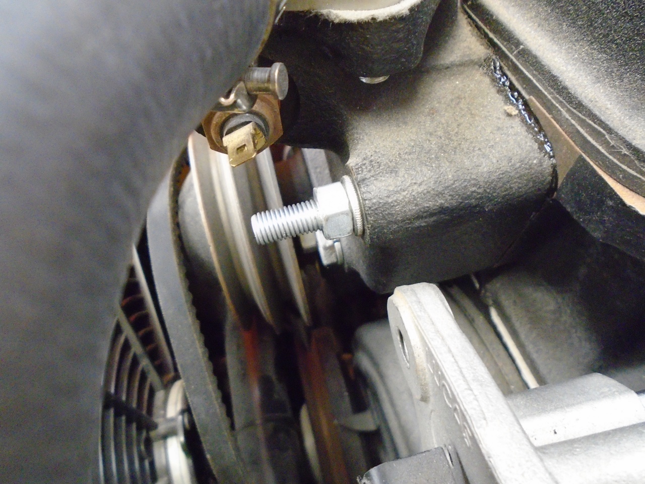
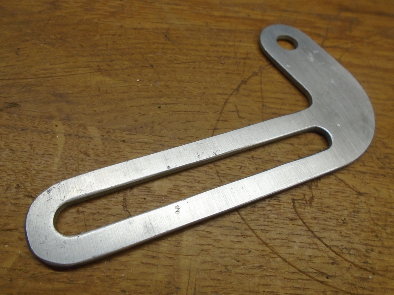
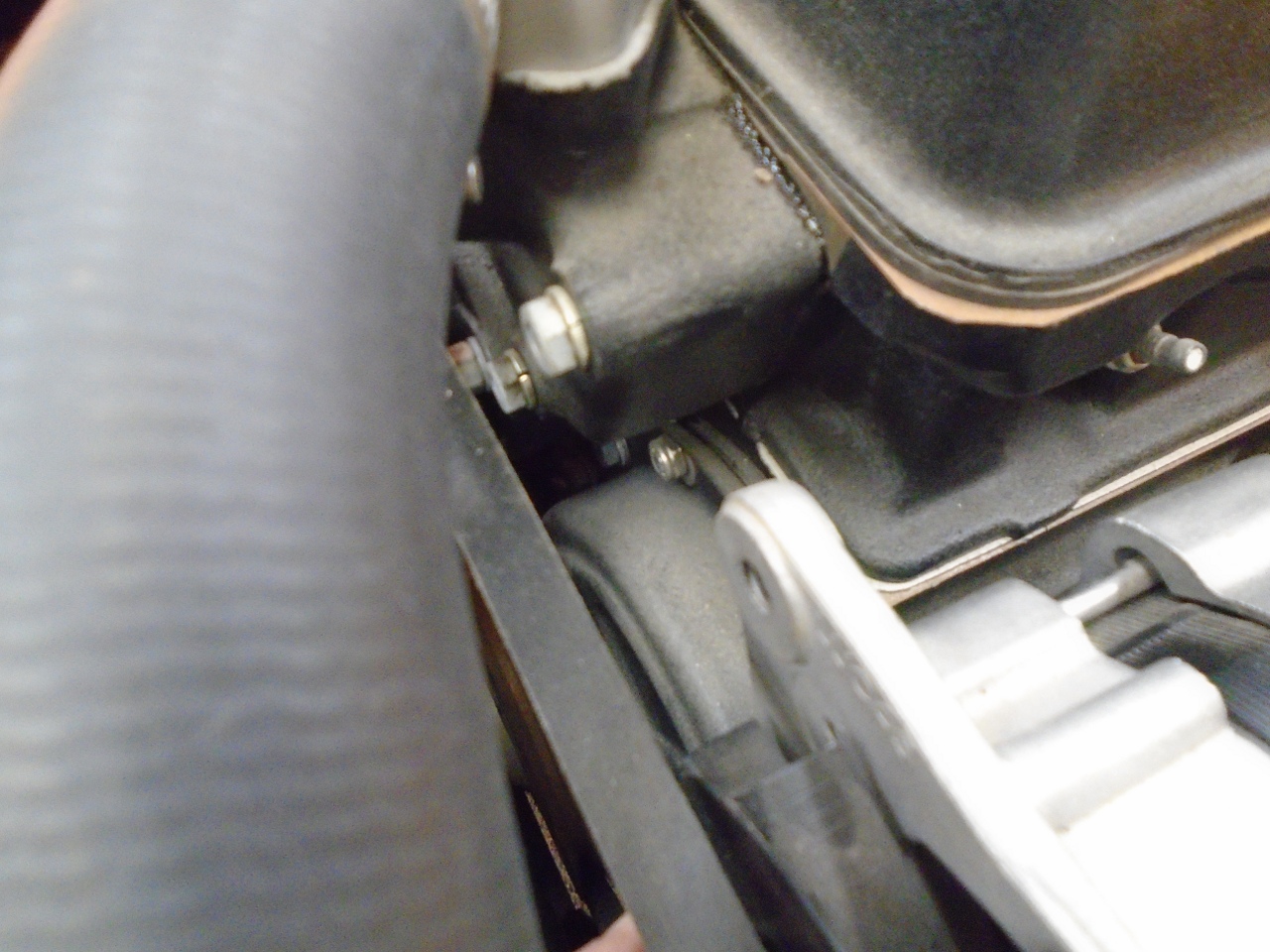
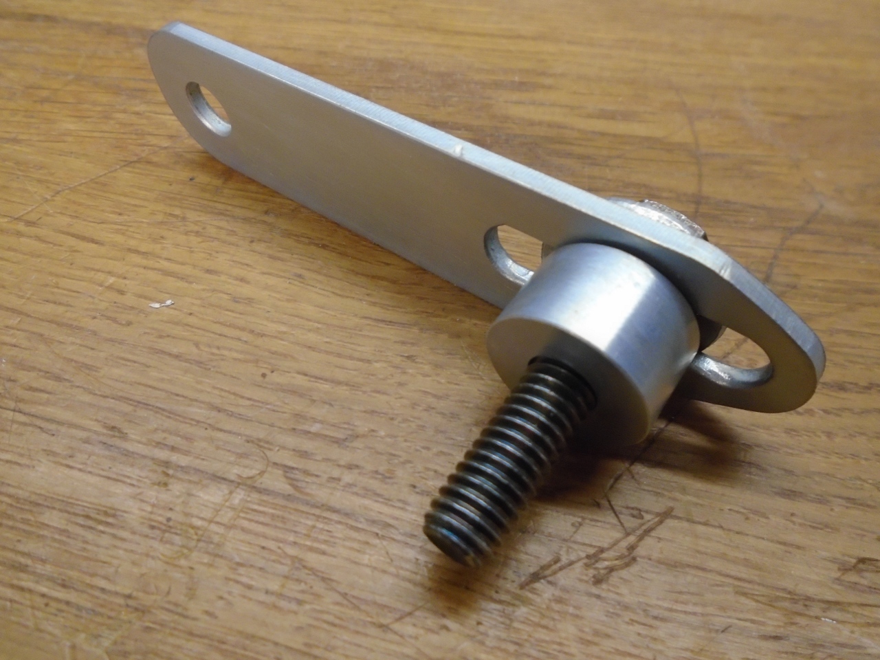
As
for the bracket itself, just a short, straight slotted strut does the
job. It provides essentially the same adjustment range as
the stock bracket in a more compact form. The spacer is necessary
since the bracket must now go on top of the hex of the new water pump
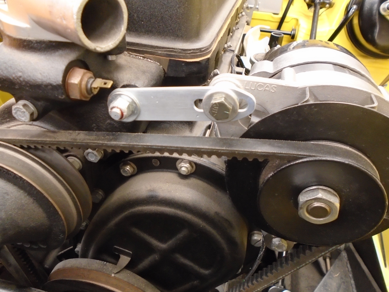
fastener. The alternator end of the bracket had to be shaped to
provide clearance to the alternator fan.
Looks cleaner to me.
Starter Wiring
I
saved wiring of the starter to this point since I knew I'd have to
remove the carbs and manifold one last time, and would have better
access.
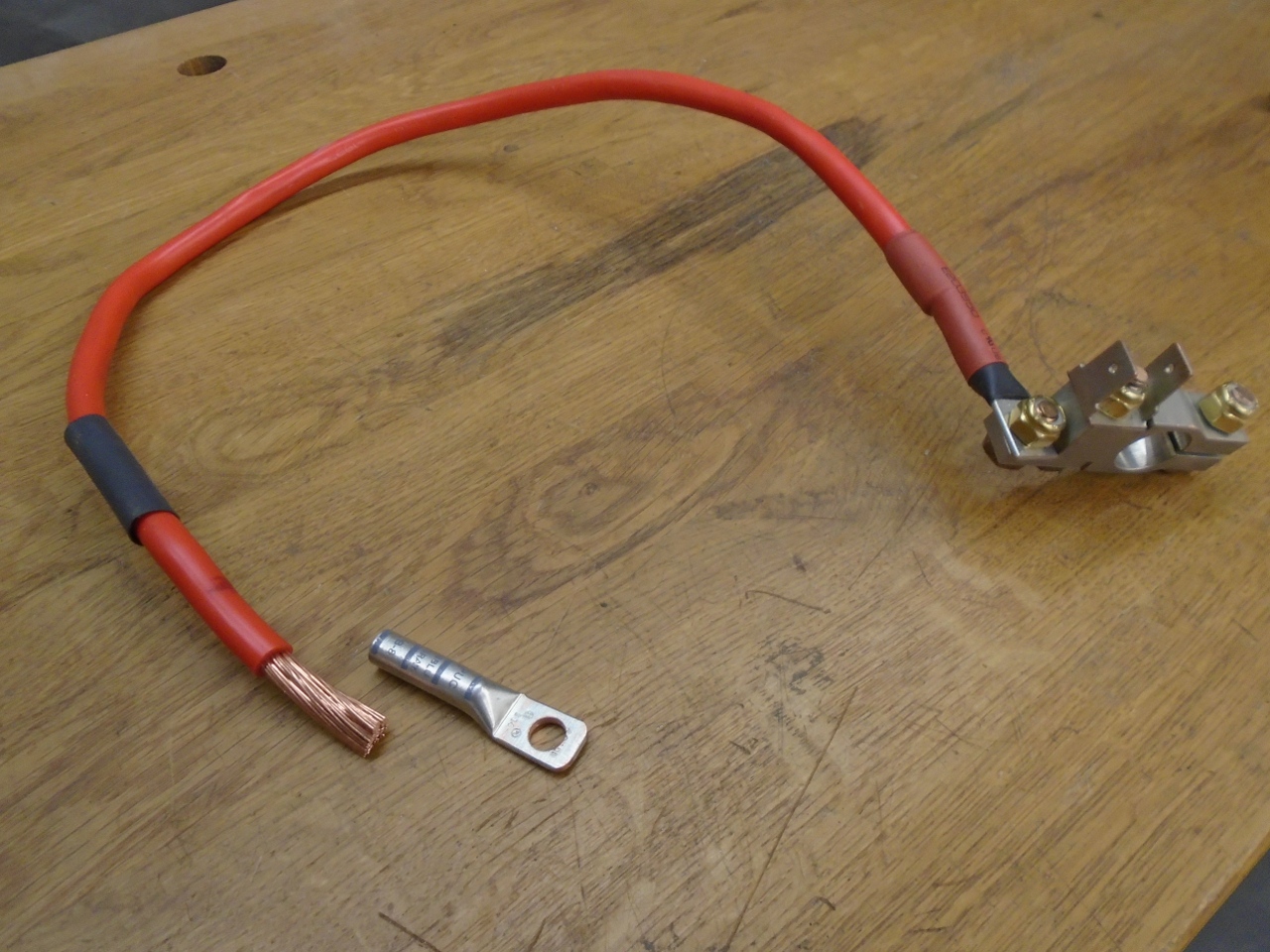
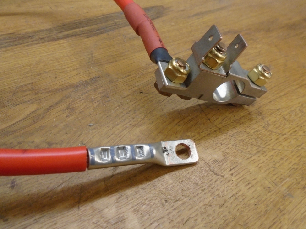
After determining the best route and length of the main
cable, I could cut it and apply the terminal. I crimp the
terminals and then apply at least one layer of "marine" heat shrink
tubing that has hot melt glue inside.
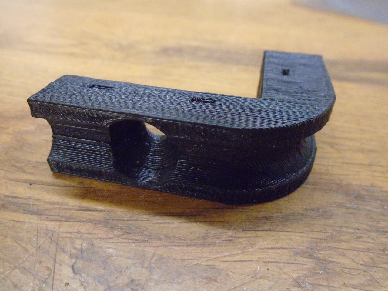
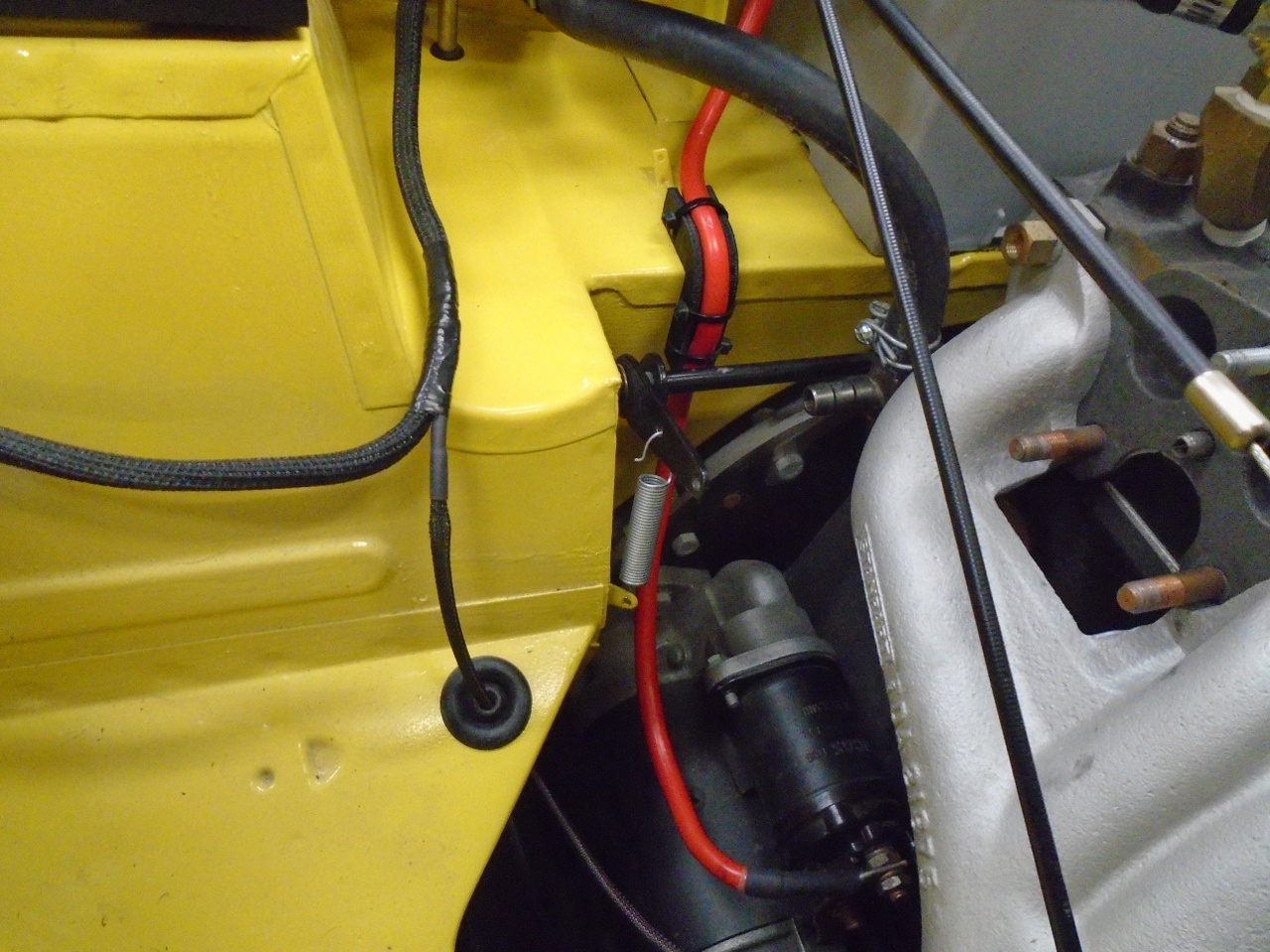
The
route of the cable goes between the accelerator shaft and the firewall.
The stiff wire wanted to rub on the shaft, so I thought I needed
some way to fix it out of harm's way. My 3D printer came to
the rescue again in making this little cable guide. It is printed
at a pretty coarse setting which is why the layers are so visible.
It took three or four iterations to get it exactly right, and the
coarse setting made the prints relatively quick.
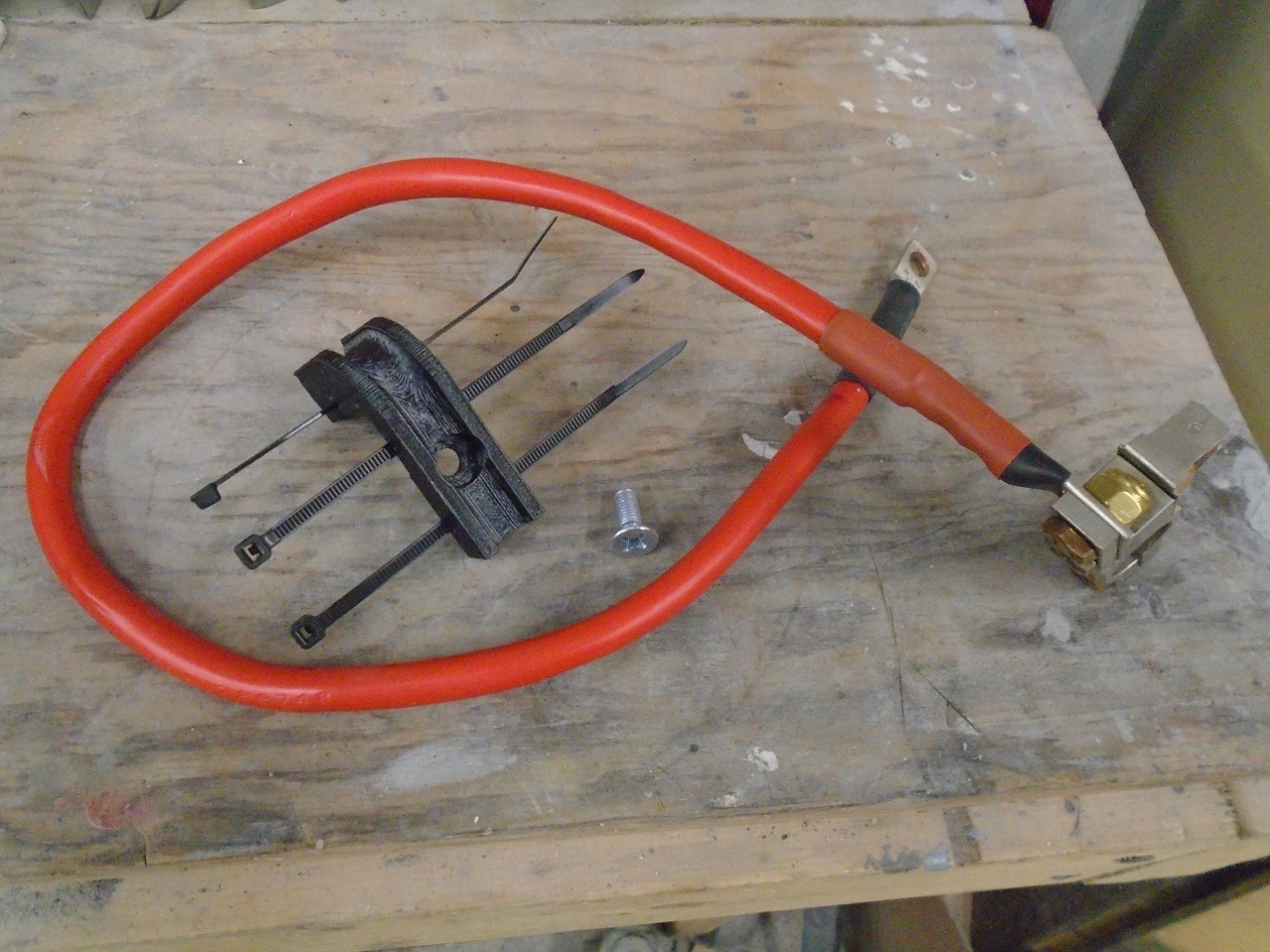
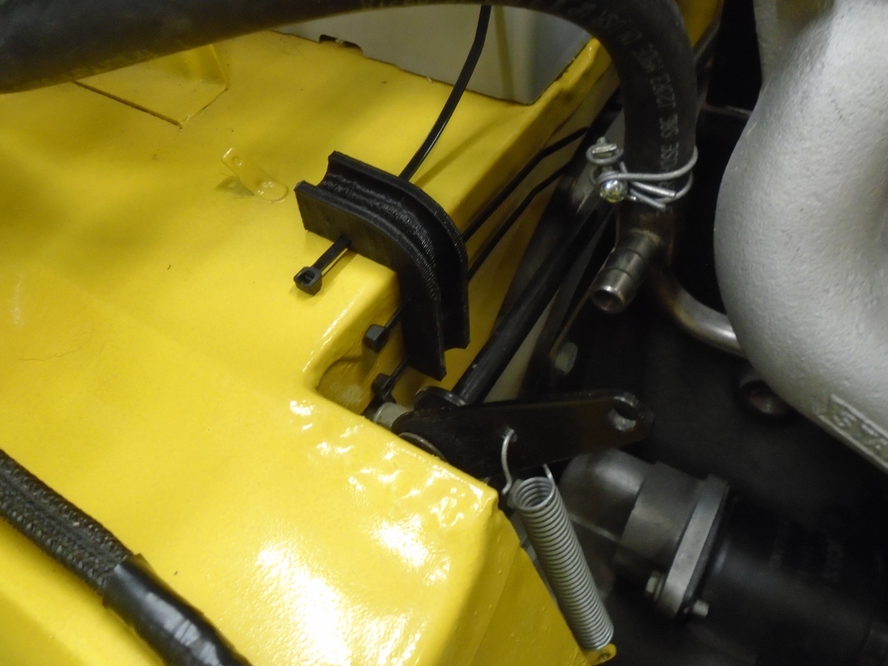
I
don't recall what it was for, but there happened to be a threaded hole
in the firewall right in the path of the cable. The guide was
fastened to that hole with a flat head machine screw.
Oxygen Sensors
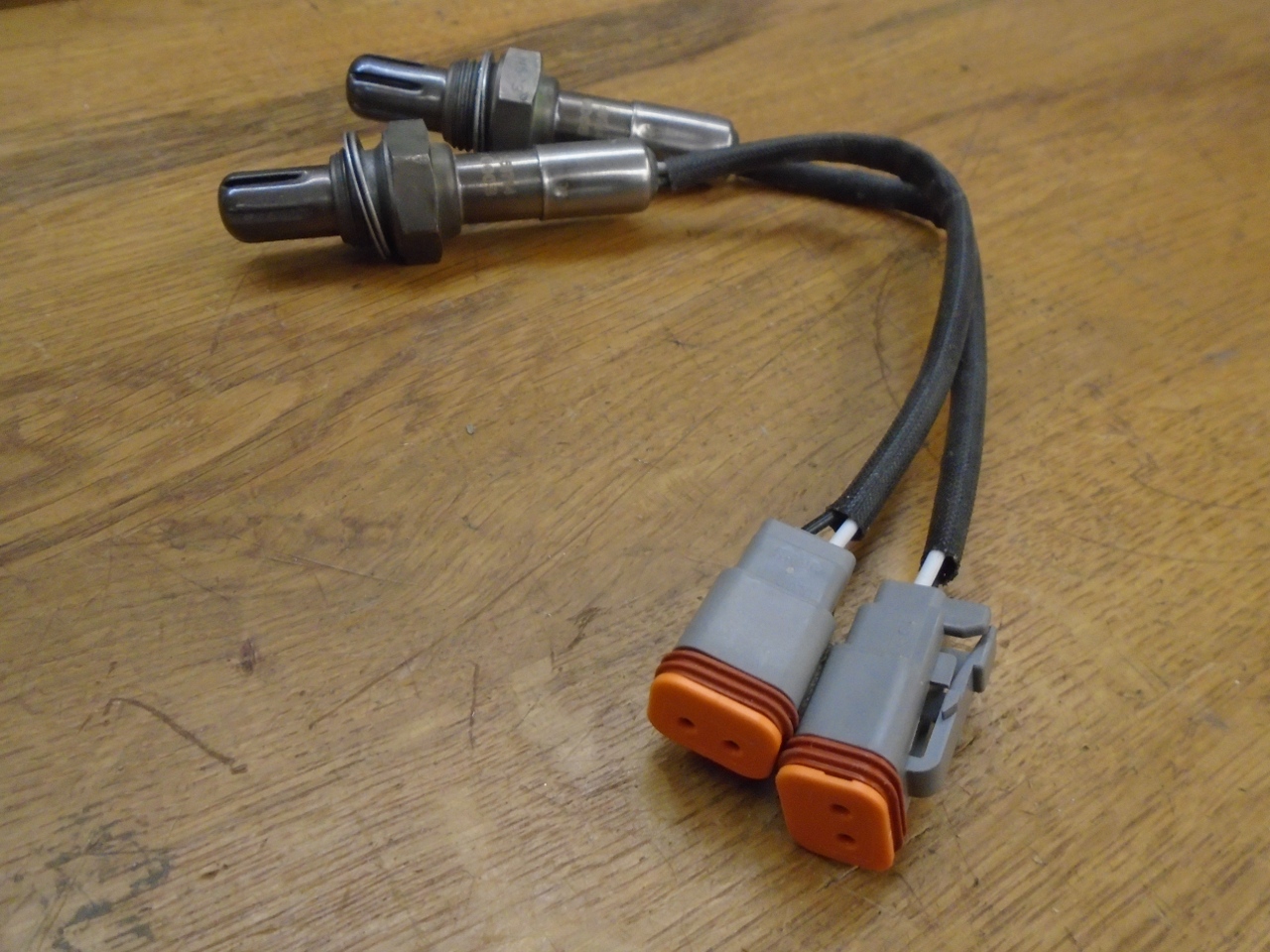
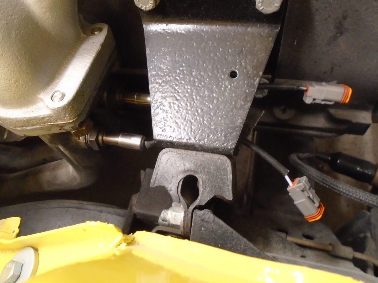
I
don't know how much I'll really use these, but I did include a couple
of threaded bungs in the exhaust down pipes for oxygen sensors.
At least in theory, they can help get an optimum tune since each
sensor would pretty much see the exhaust from the cylinders fed by one
of the carburettors. I put some water tight automotive connectors
on the leads. I had previously cut about a two inch hole in the
web of the motor mount for the connectors to pass through.
Manifold Coolant Tube
Ever
snce I replaced the rotted out coolant tube in the intake manifold with
a nice new polished stainless one, I was a little worried that I didn't
somehow put a bead on each end of the tube.
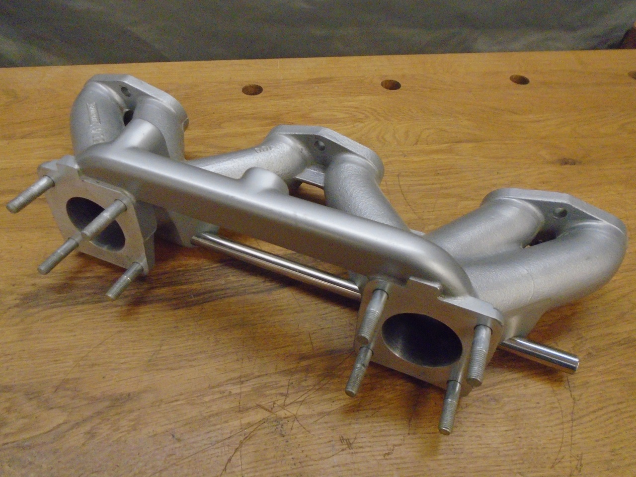
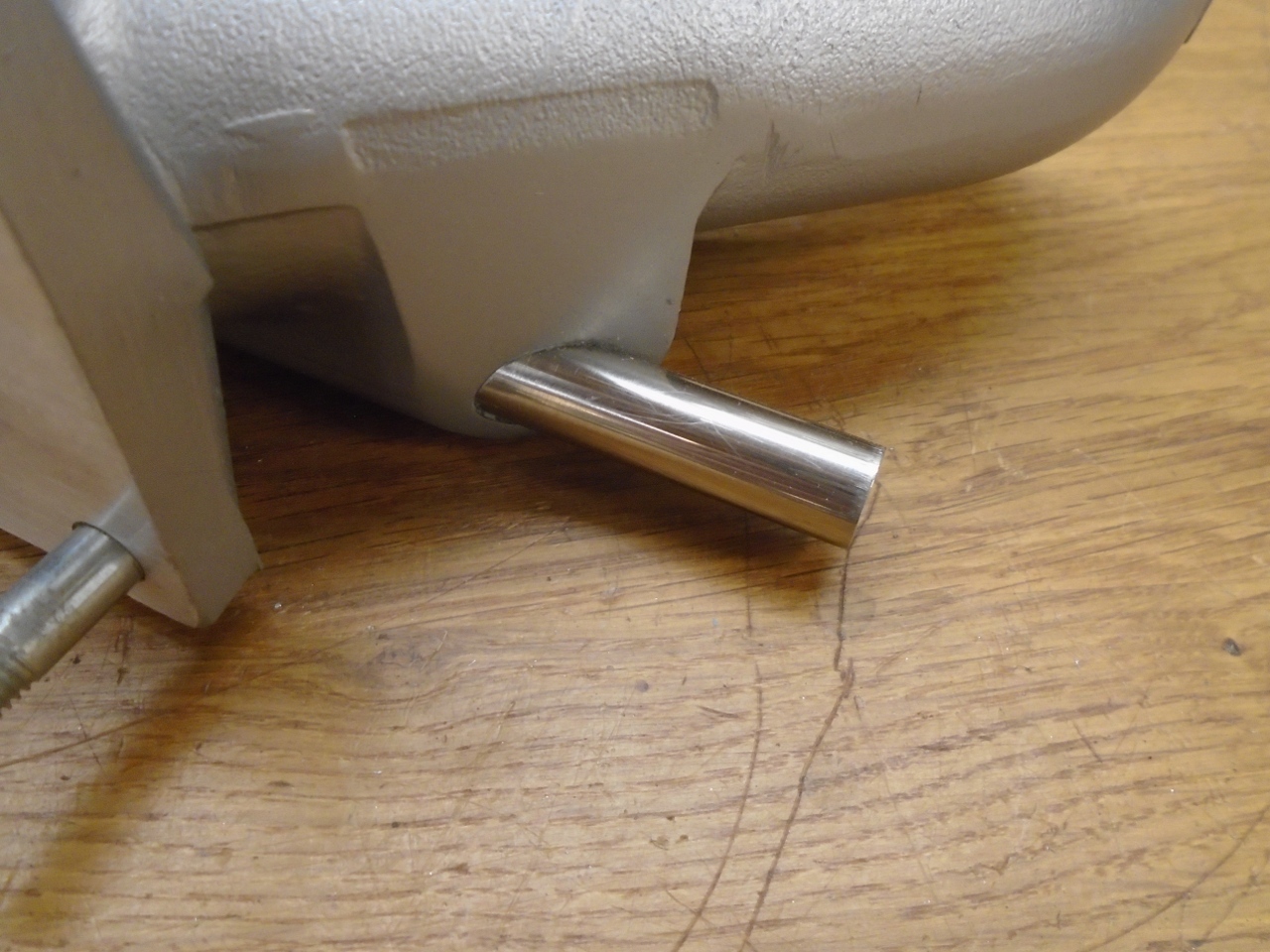
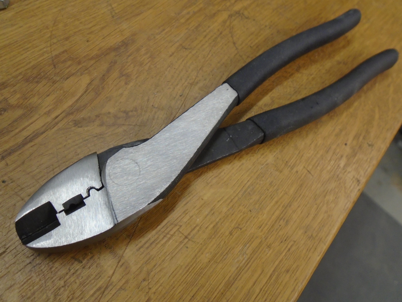
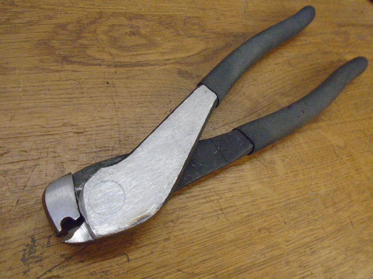
A
bead with a hose clamp behind it makes a hose slipping off very
unlikely. At the time, I just didn't see a good way to put beads
on that tube. Well, I wish I could take credit for this idea, but
I got it from YouTube. A pair of cheap utility pliers from Harbor
Freight can be modified to make a pretty nice bead. The stainless
in this tube is pretty tough, but with some muscle, it worked OK.
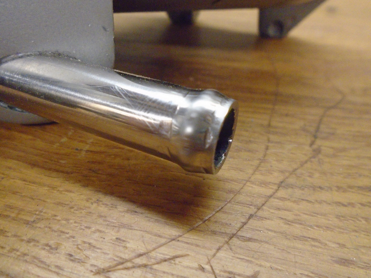
I sleep better now.
Crankcase Ventillation
If
the crankcase of an internal combustion engine is sealed, pressure will
build up inside due to blow-by gasses leaking past the piston rings.
Internal pressure causes leaks, and may encourage gasket failure.
Beyond this, water vapor and unburnt fuel in the blow-by can
degrade the oil. Various methods have been used over the decades
to provide ventilation of the crankcase, from simple road draft tubes
to PCV valves that provide a regulated vacuum from the intake system to
the crankcase. My TR6 and some similar cars that use "constant
depression" carburettors use a special port on the carbs that
provides a relatively constant vacuum to the crankcase. One
curious thing to me is that the factory system uses a non-vented oil
filler cap on these systems, and there is a felt seal on the dipstick tube. This
means that there is no provision for significant fresh air to enter the
crankcase. This implies two things: The crankcase will
continuously run approximately at the constant vacuum that the
carbs provide, and the gas flow into the carb ports will be limited to
whatever the blow-by is. It's possible that factory engineers
went this way to avoid upsetting carb mixture with too much ventilation flow.
I
considered several approaches to crankcase ventilation, but in the end,
decided to stick with the Stromberg's constant vacuum ports. I
think a PCV valve could work fine, but it would be an additional
maintenance item and failure point with little if any added benefit.
My system will be simpler than original though, since the factory
equipment included the charcoal canister in the ventilaton circuits,
and I'm not using the canister.
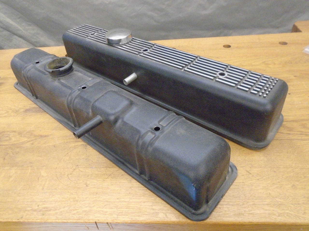
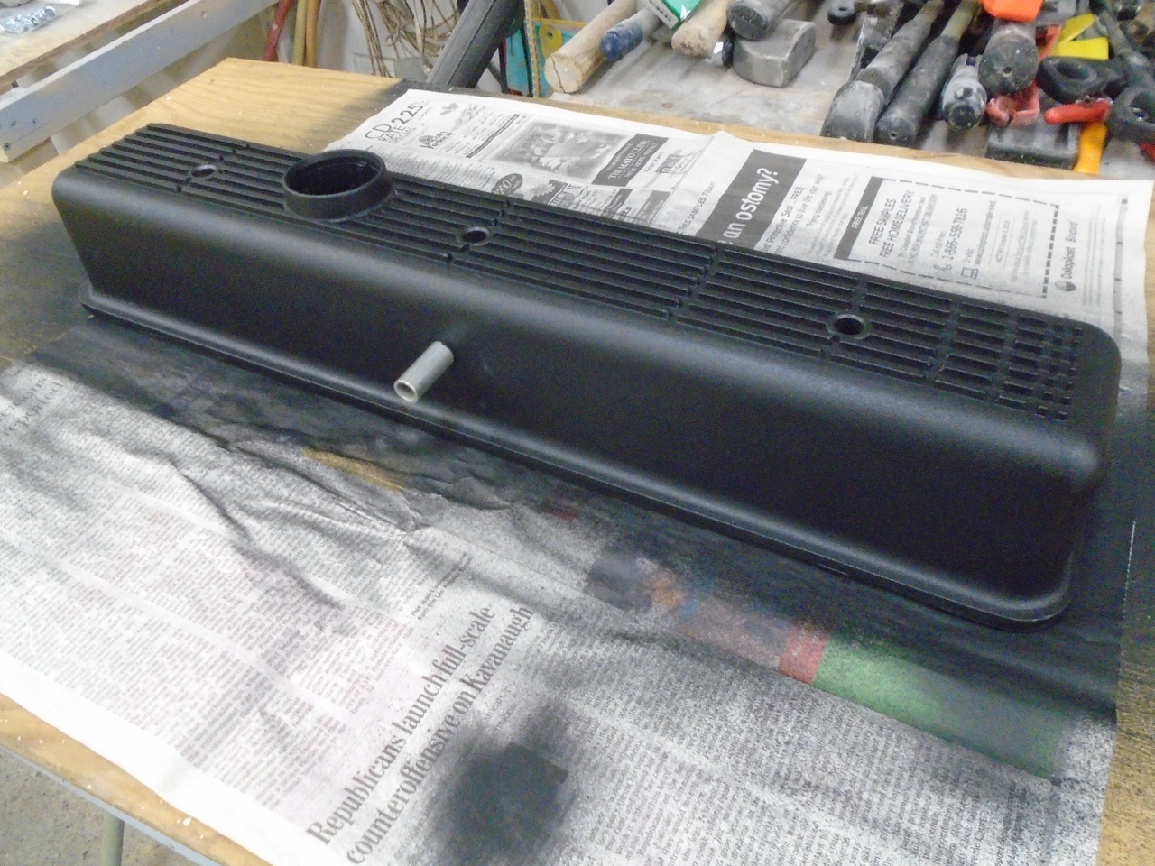
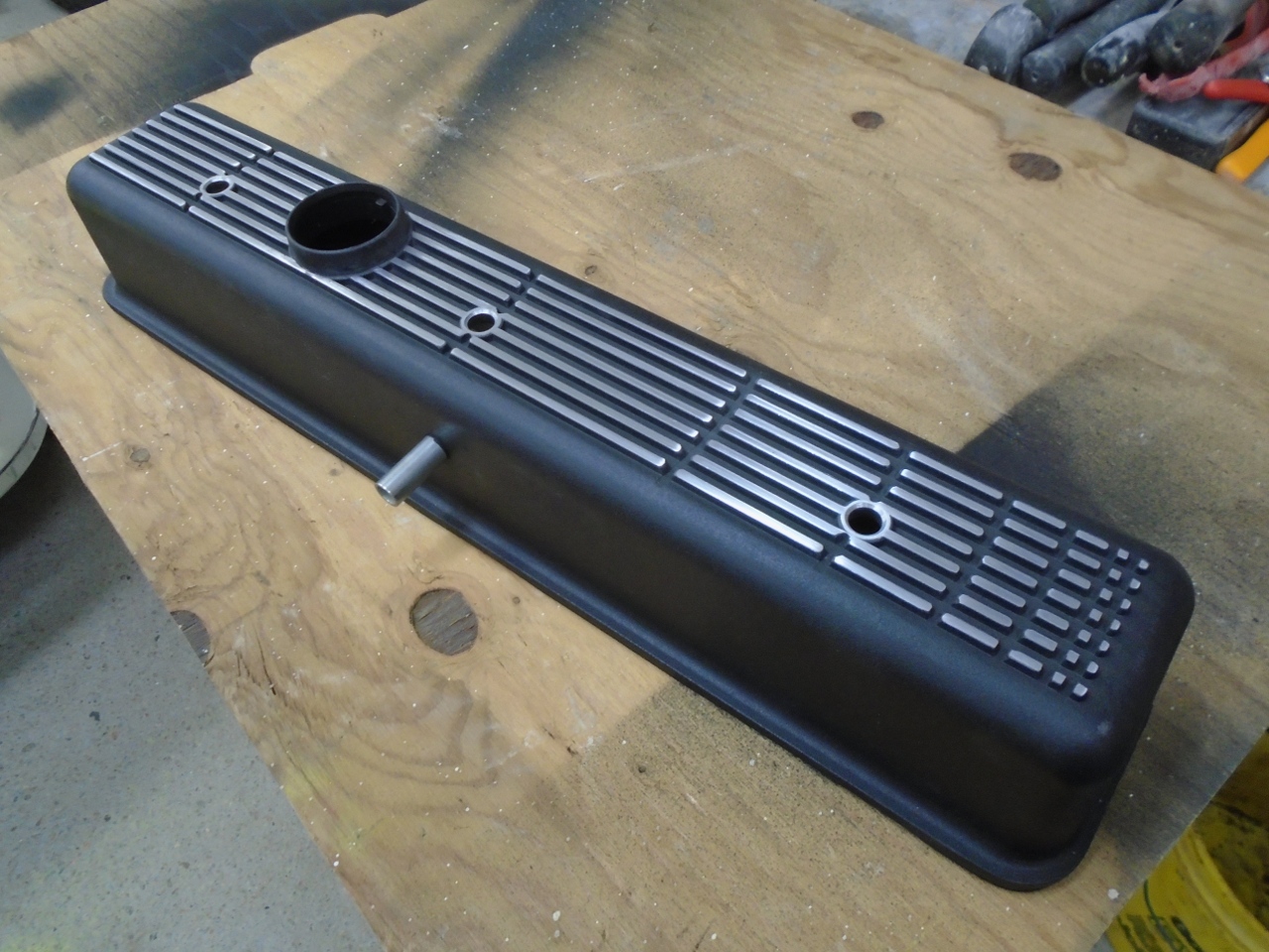
The
ventilation system starts with the valve cover. I'm using a cast
aluminum cover that is different from the stock cover in at least one
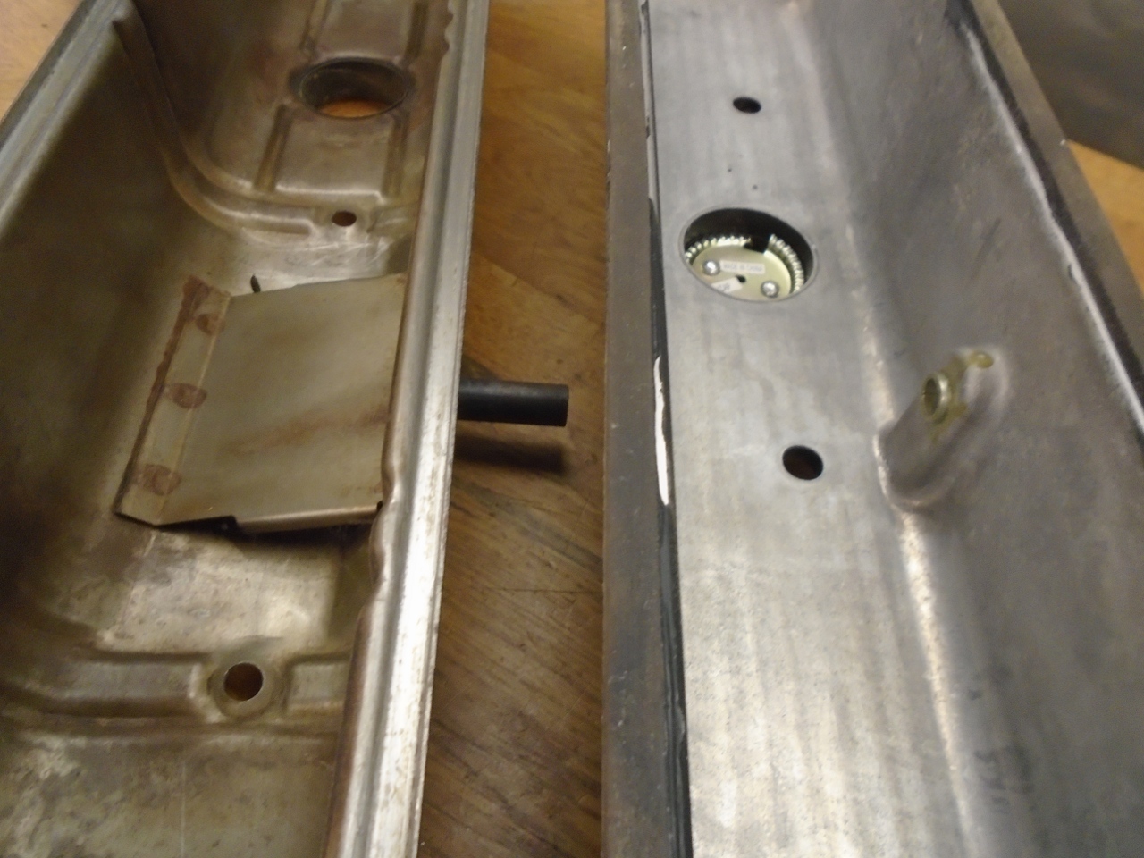
way relavent to ventilation. The stock cover has a baffle over
the ventilation port, while the new one does not. A lot of oil
can get airborne inside the crankcase, and some of this will make its
way to the valve cover and the port. We typically want to keep
oil out of whatever is downstream from that port--the carbs in my case.
Some
people have installed an oil separator device at this port to catch the
oil before it gets to the carbs or PCV valve. I hoped that just
installing some kind of baffle would make a separator unecessary.
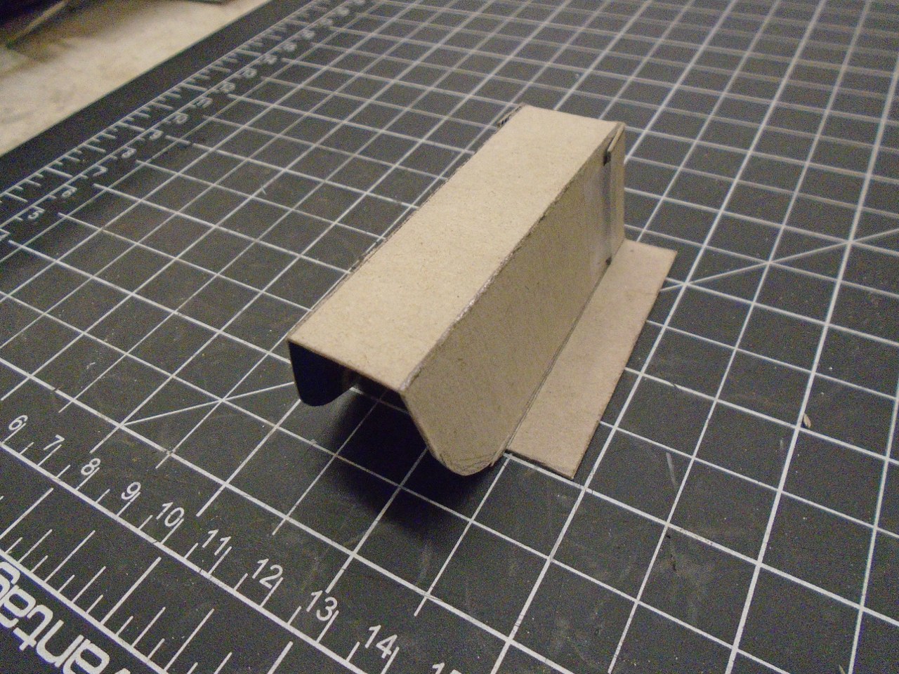
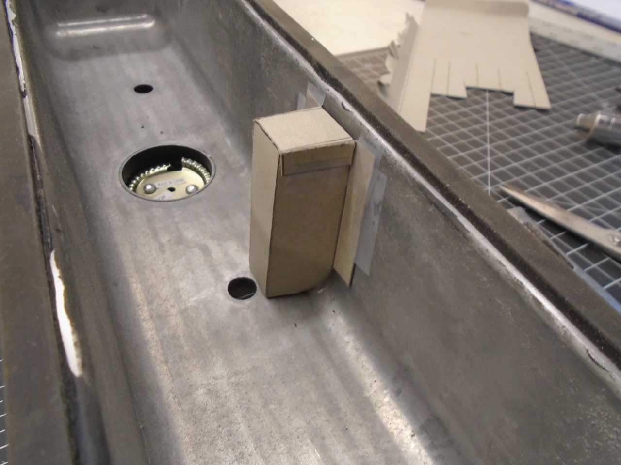
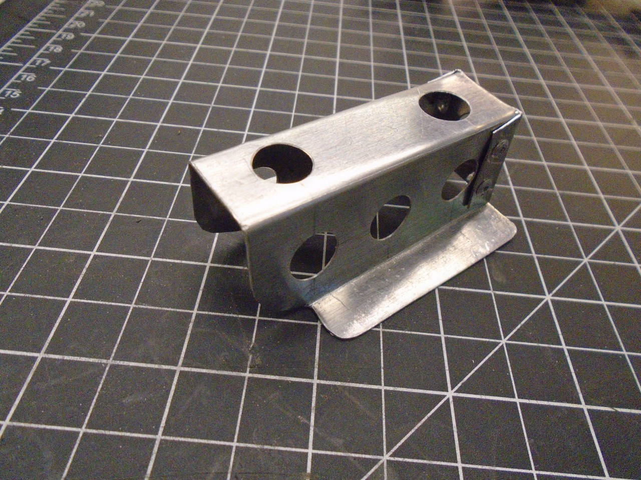
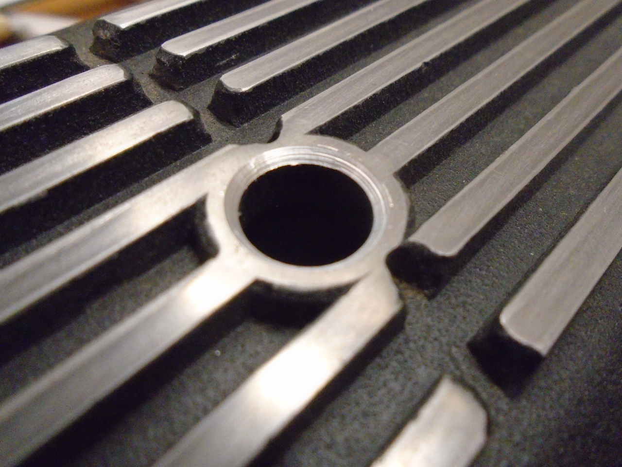
There
really isn't a lot of spare room inside the valve cover. The
baffle obviously has to go over the port, but it has to extend into the
appoximately one inch space between the #6 and #7 valve springs.
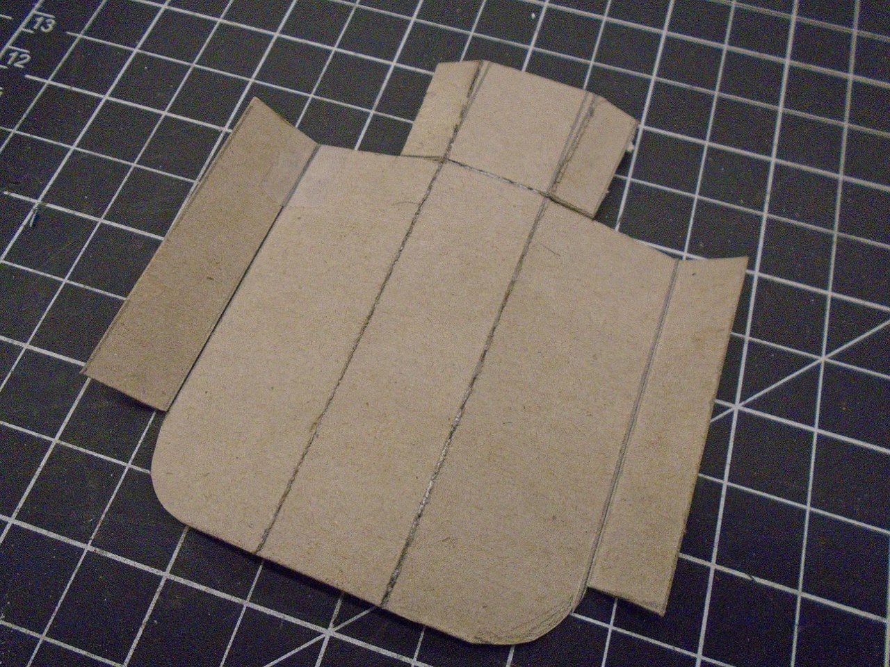
A cardboard mockup:
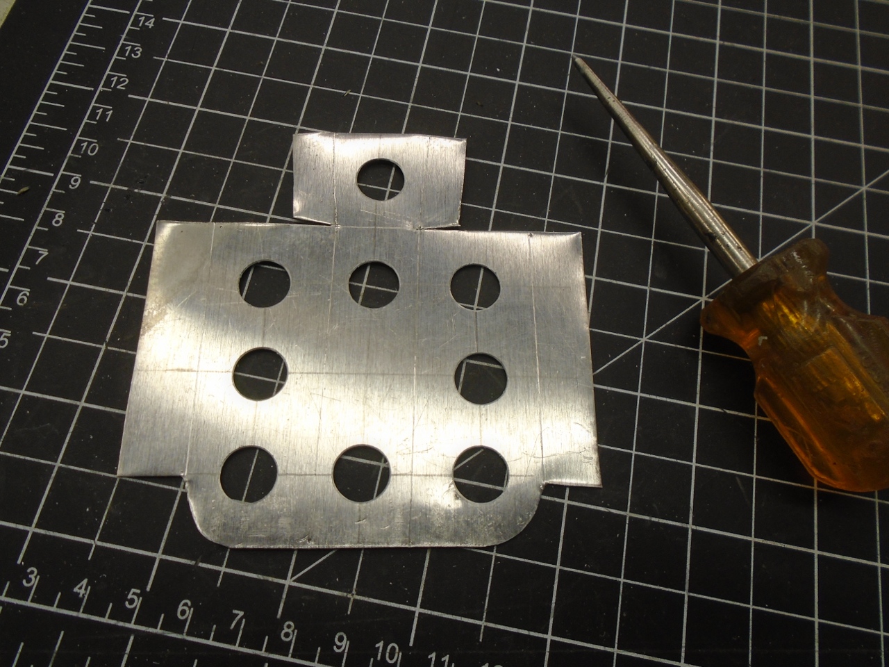
Then to some thin sheet aluminum:
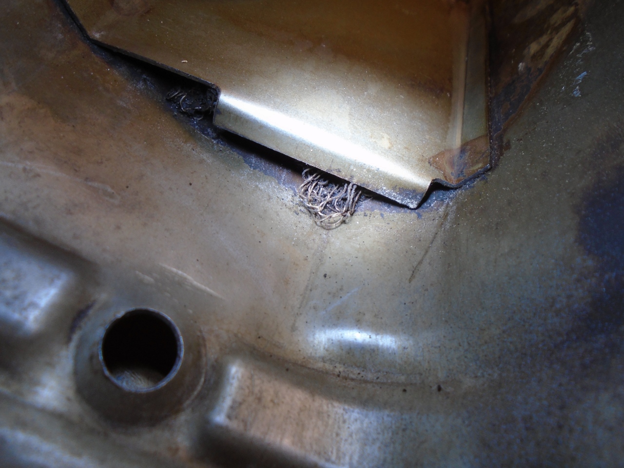
I
suspected that the original cover's baffle might have some kind of mesh
inside to capture oil droplets and mist. I was right. I was
able to drag a little bit of it out with a probe.
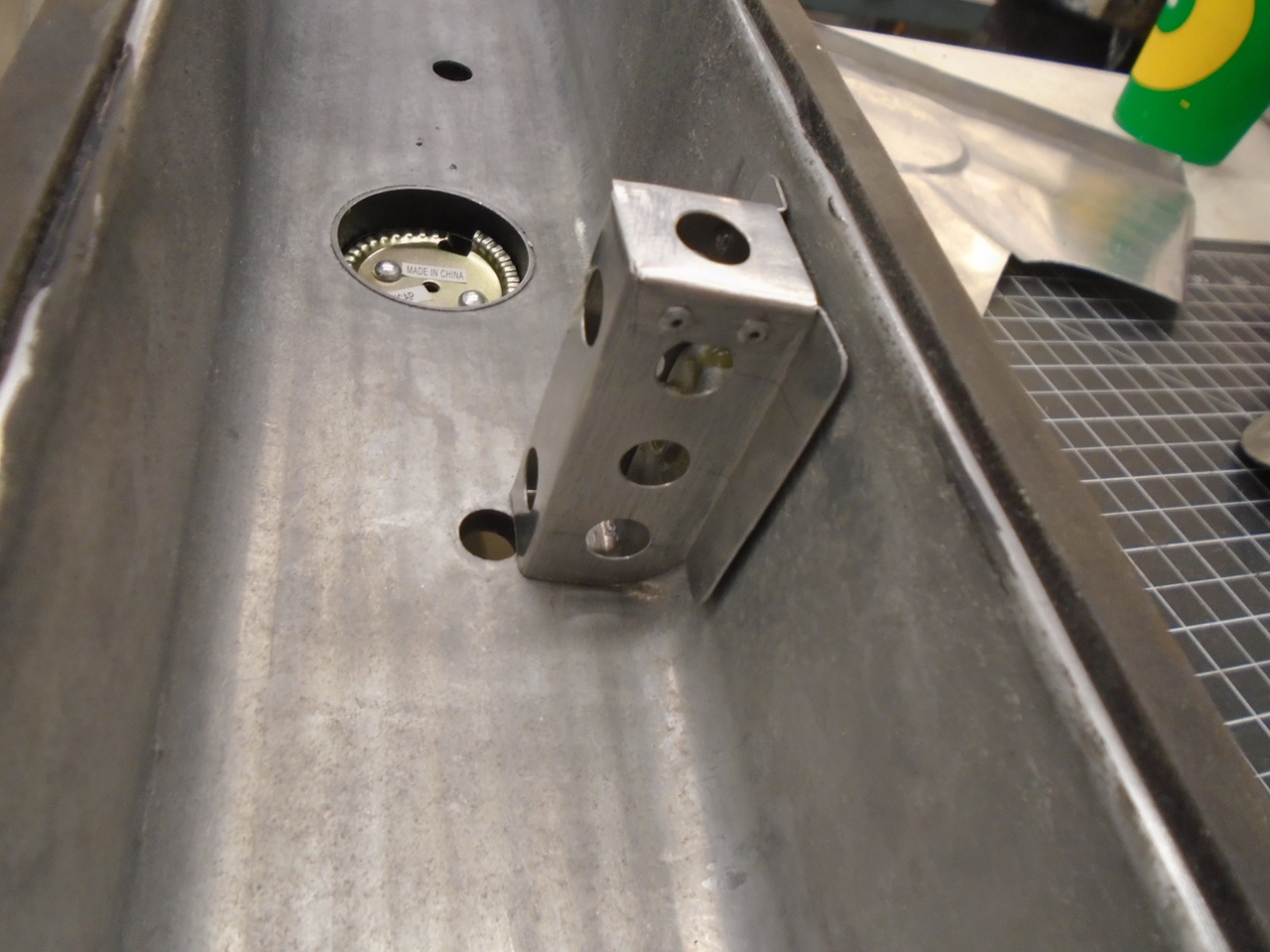
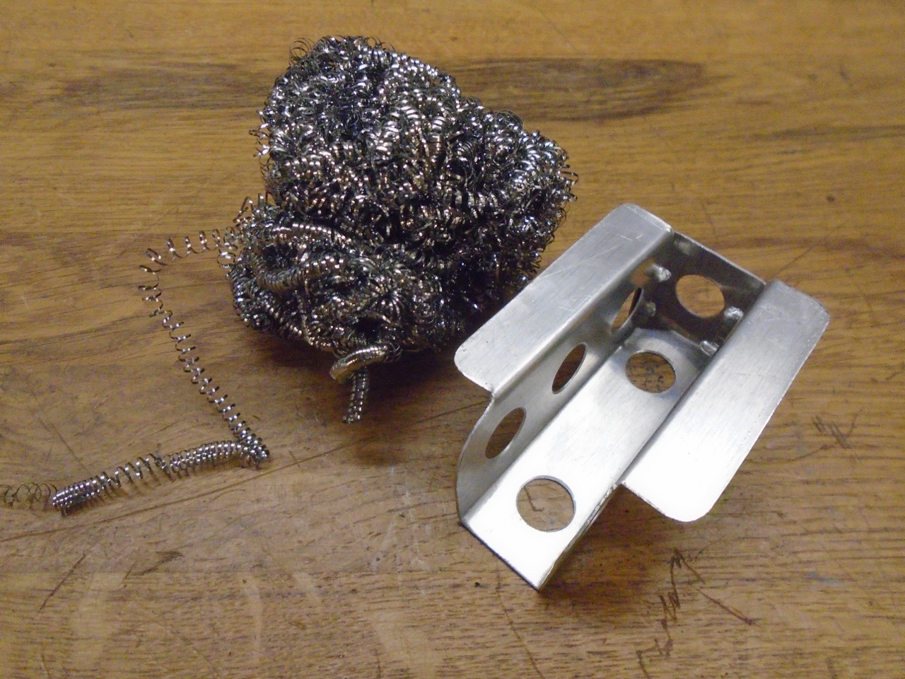
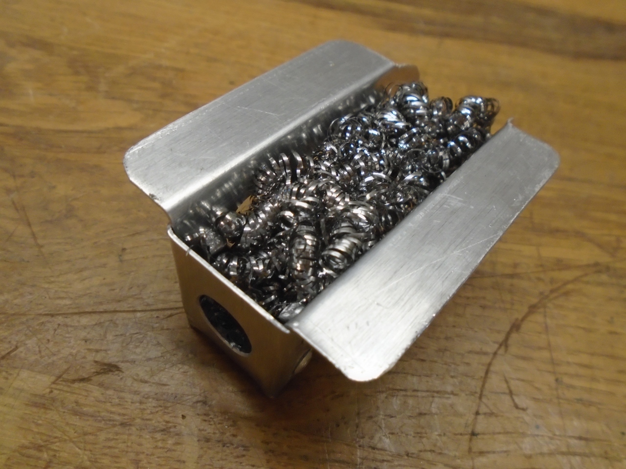
For
the new baffle, I used some stainless steel mesh. If it looks
like a pot scrubber, it's because that's what it is.
Spot welded to the cover...
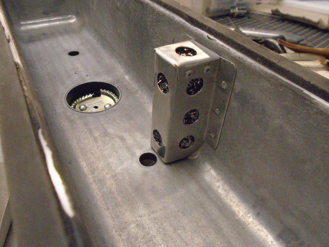
...which meant I had to paint it again.
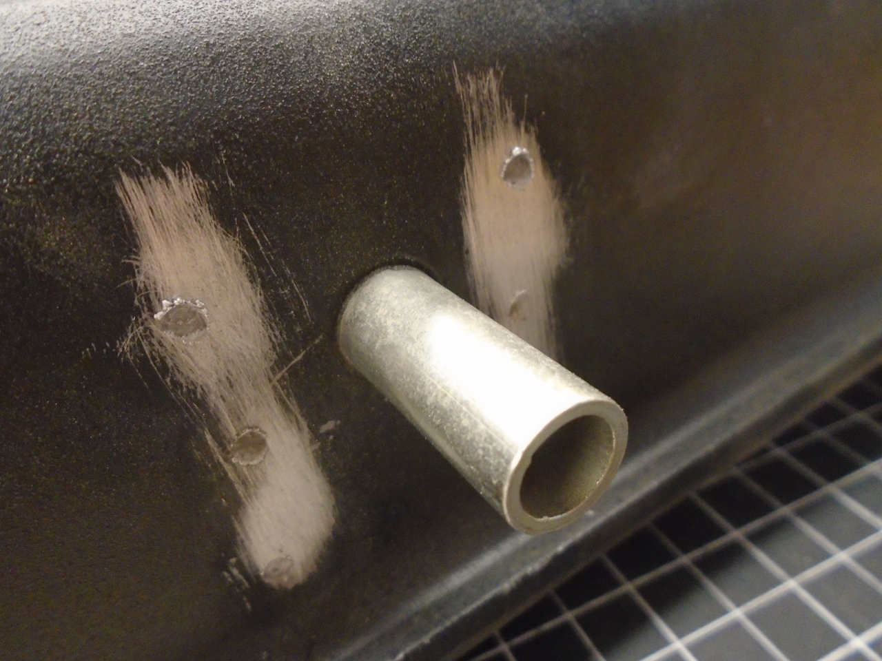
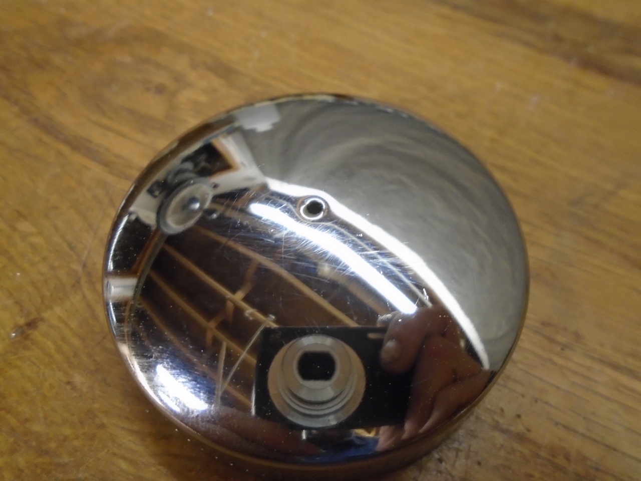
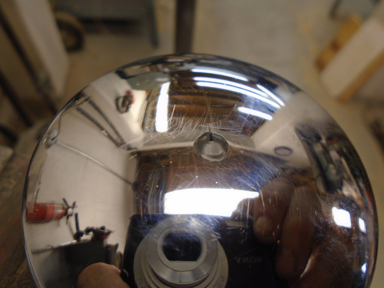
The
cap on this aftermarket valve cover had a vent hole in it. Since
the factory apparently wanted this ventilation system sealed, I plugged
the hole with a little dollop of Plastidip.
One last thing with the cover was to add some countersinks at the fastener holes to allow some O ring seals under the nuts.
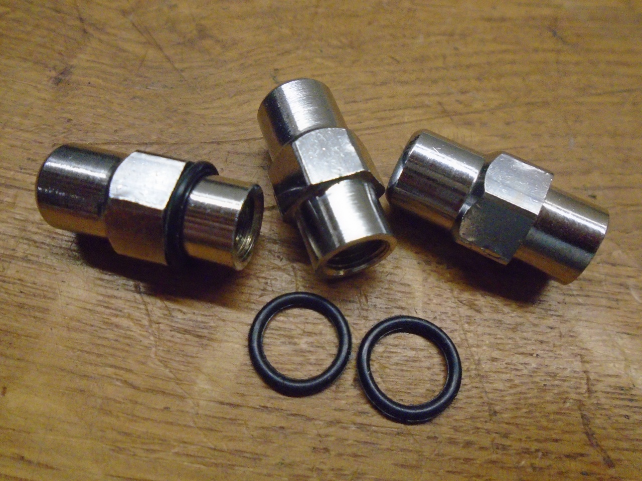
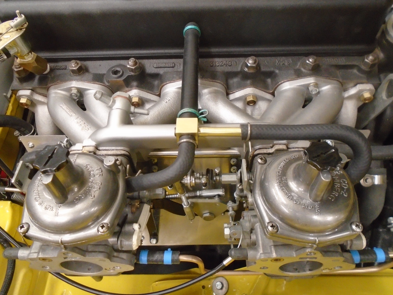
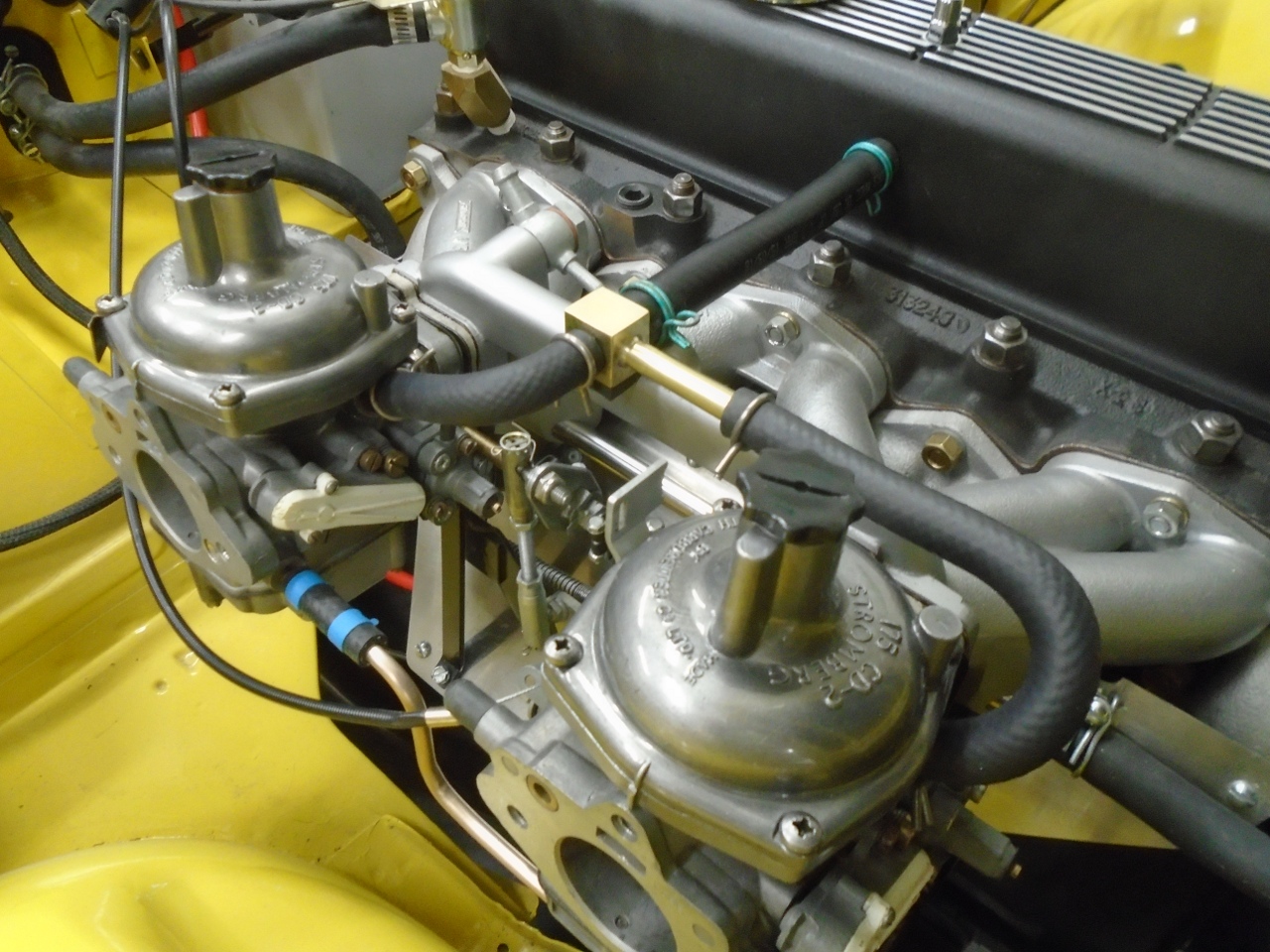
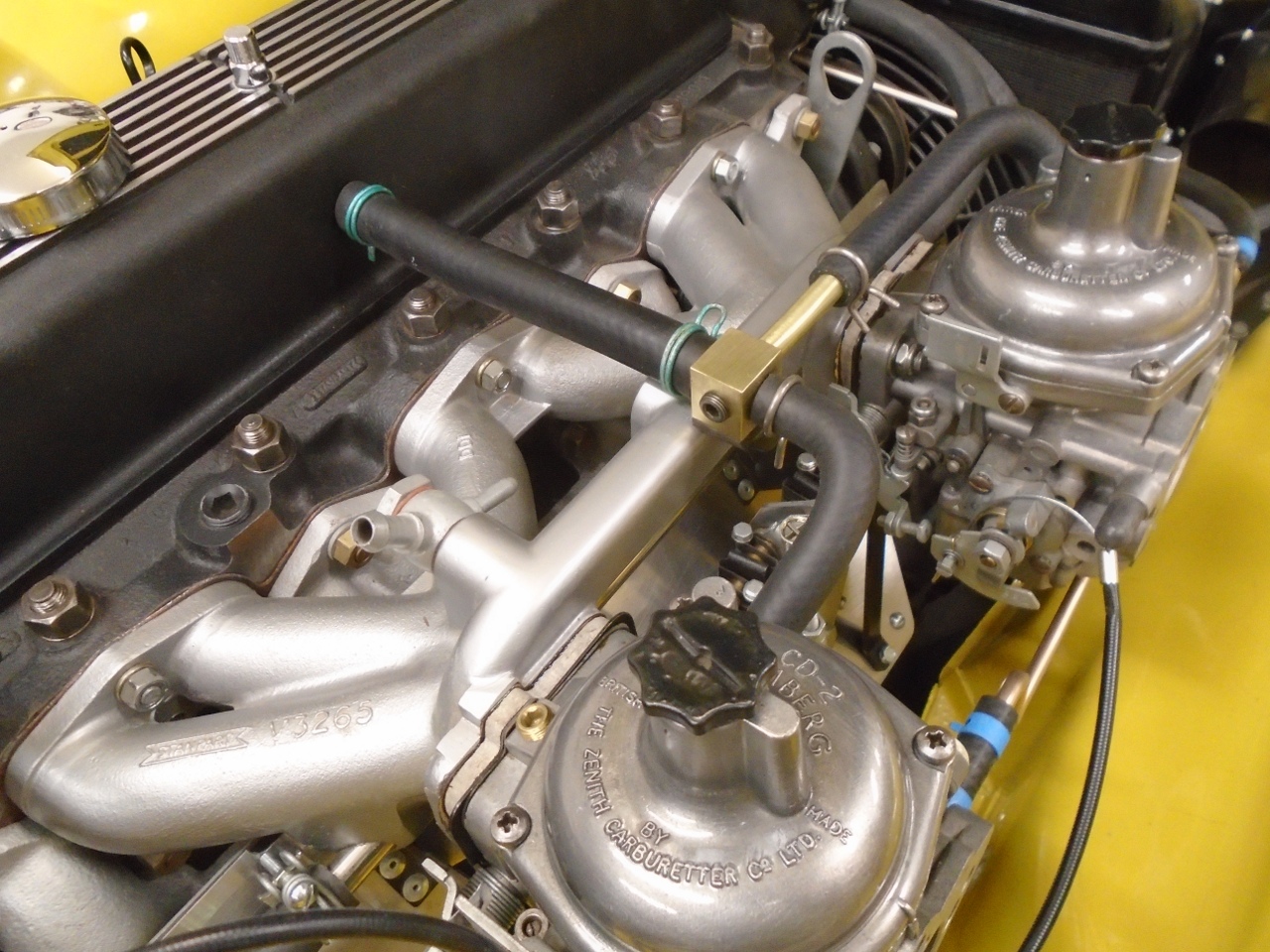
Then
for the rest of the ventilation system. The piping just includes
connections between the evacuation ports of the carbs and the valve
cover port. The only small wrinkle here is that while the carb
ports are 3/8", the cover port is 1/2". Not to worry, though.
I made this little bespoke fitting with the required size
connections. I also added the barbed fitting as a fourth port.
I've always been curious about the "constant" vacuum at the
evacuation ports, and how it behaves with different throttles and
loads. I'll probably have that port plugged in normal use.
I made the neatest installation I could with the hoses I had available.
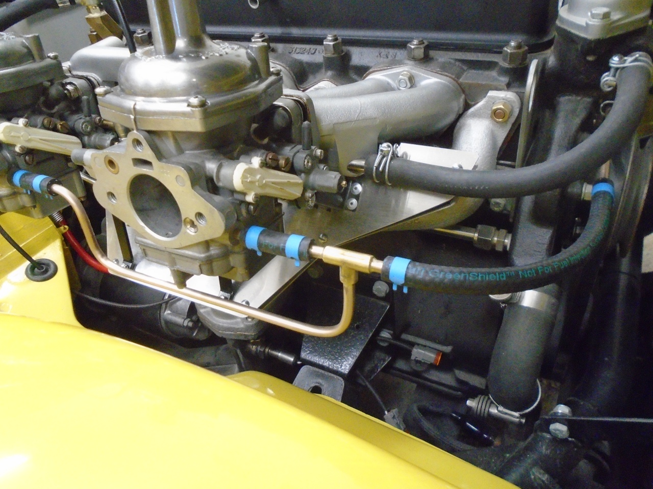
Fuel Lines
From
the fuel pump, there are two hard lines that serve the carbs: a
1/4" line from the pump, around the front of the engine, and to the
right side, and a made-up 1/4" assembly that feeds the two carbs.
They are joined by a section of rubber hose. I think my
lines were serviceable, but looked pretty rough, even when cleaned up.
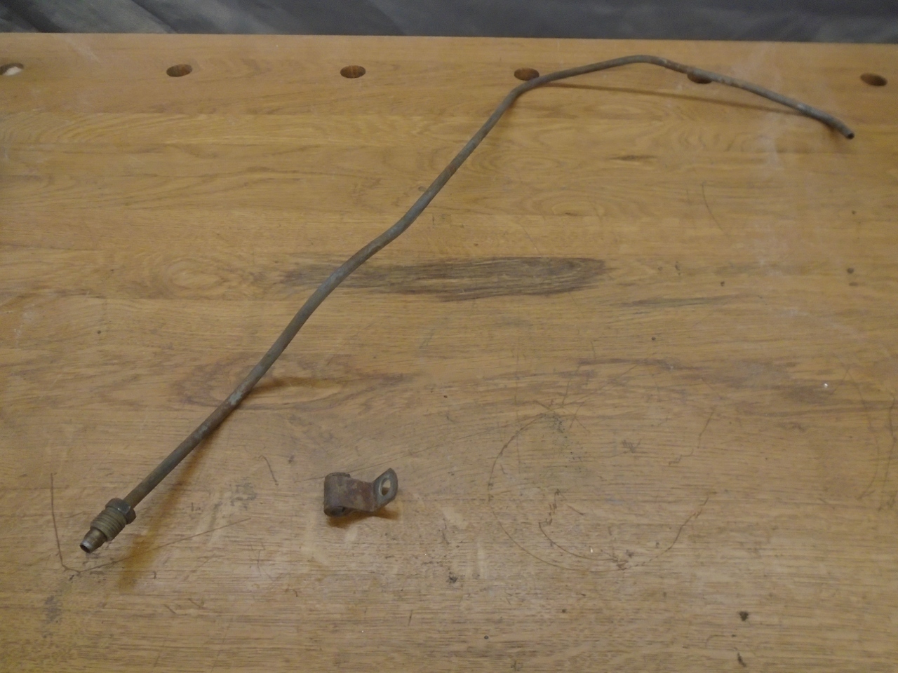
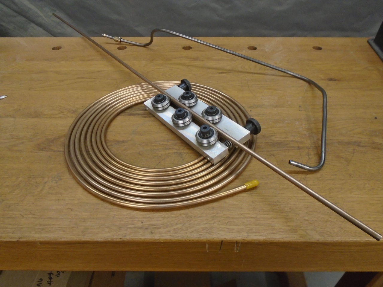
I
had enough Cunifer line left over from the brake lines. Cunifer
won't corrode, and is easy to bend without kinking. I find it's
best when trying to duplicate a shape, to start with a straight piece
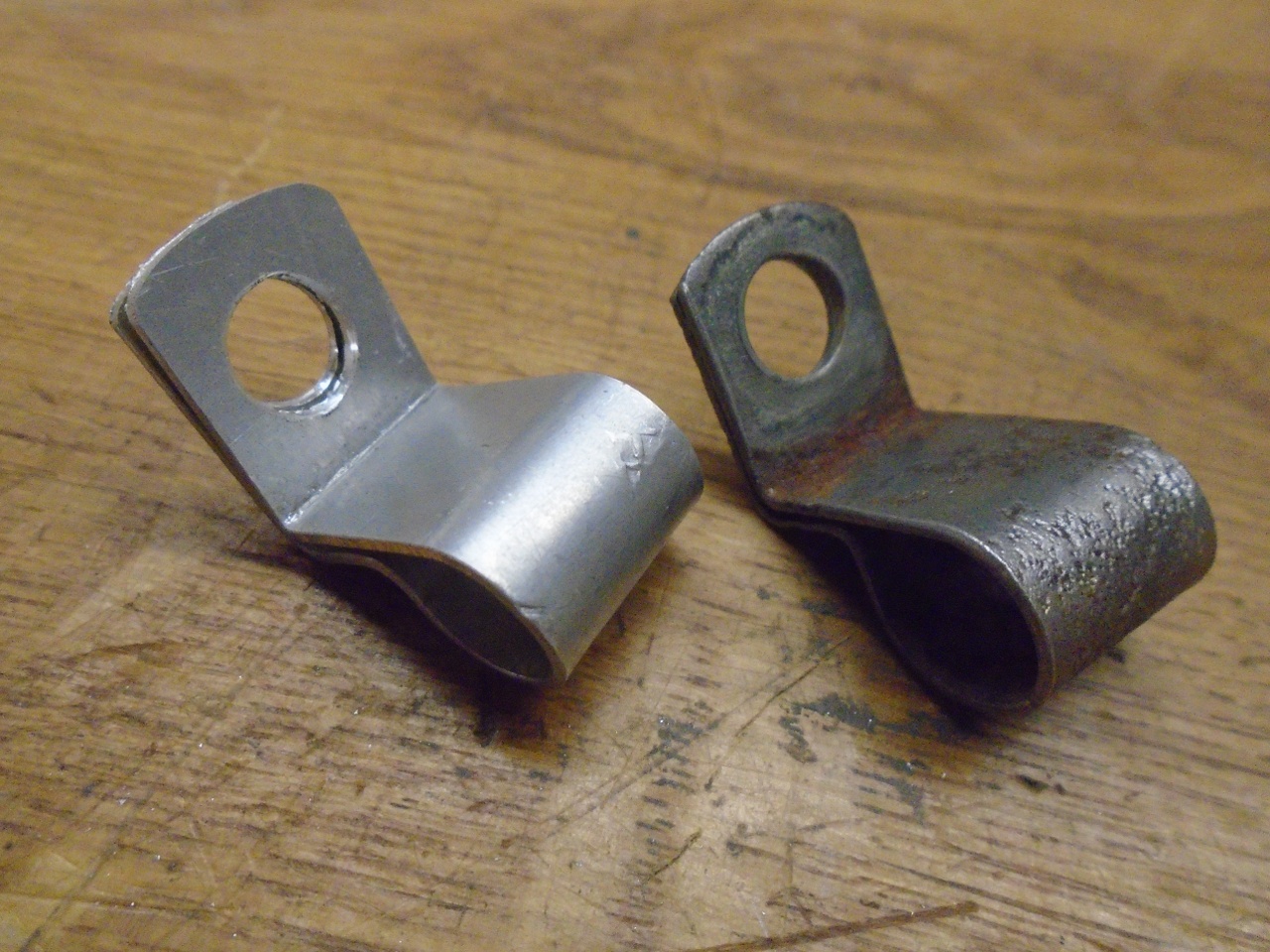
of tubing. Also made a new tubing clamp for the front of the
engine.
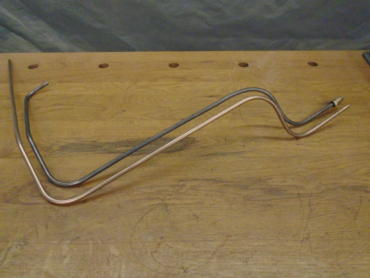
I'm not sure of the exact route of the line, but judging from the shape of the original, this can't be too far off.
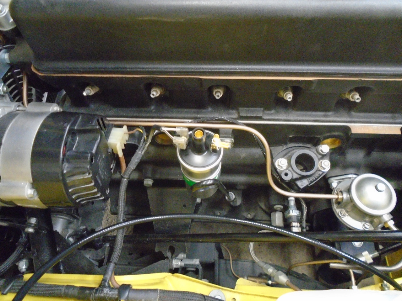
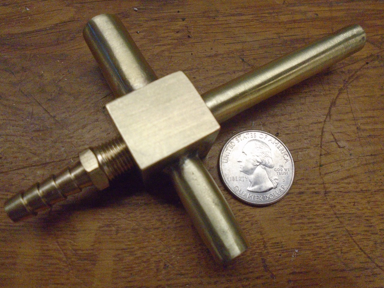
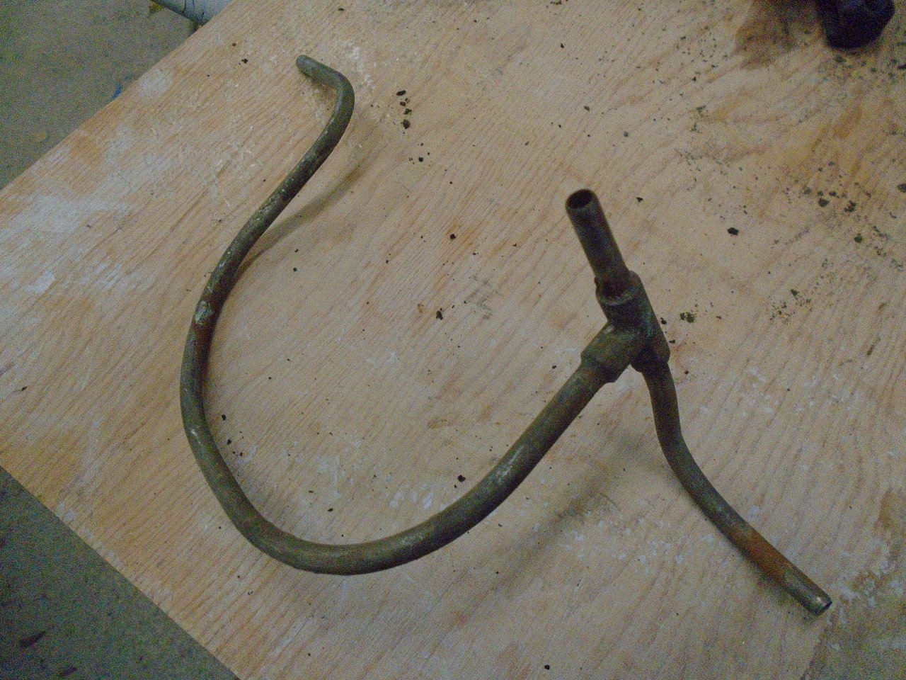
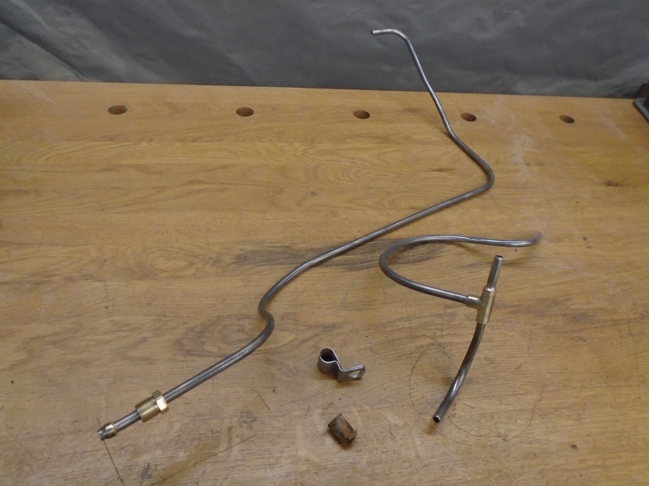
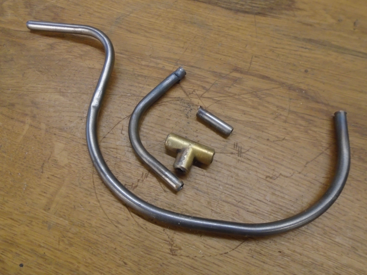
The
splitter tube for the carbs was a little more involved. I thought
I could improve on at least the looks of the tube, but I couldn't find
a T fitting as compact as the original. I ended up cutting out
the original T, drilling the ports, and using it in my new part. It's a hybrid of old and new.
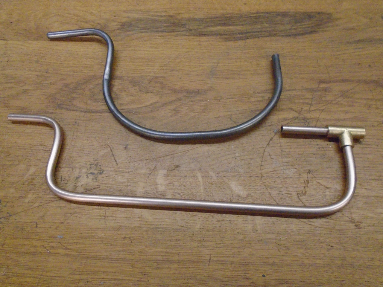
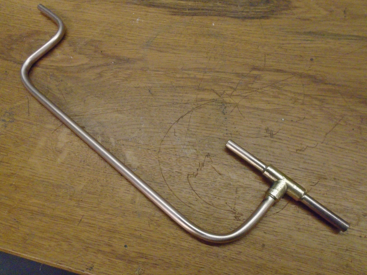
Even though it isn't very visible with the air cleaner on, it looks a lot neater than the original fuel line.
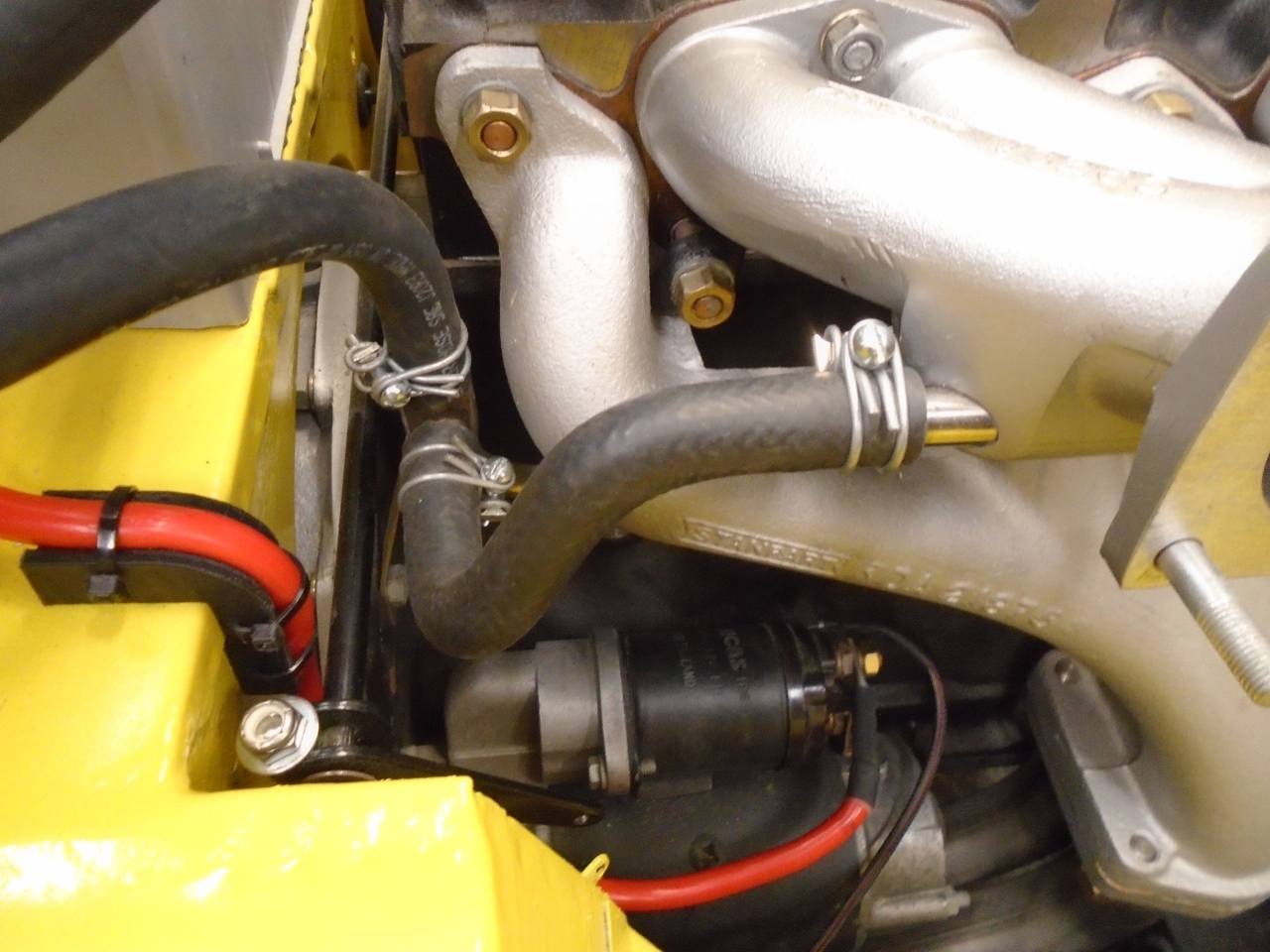
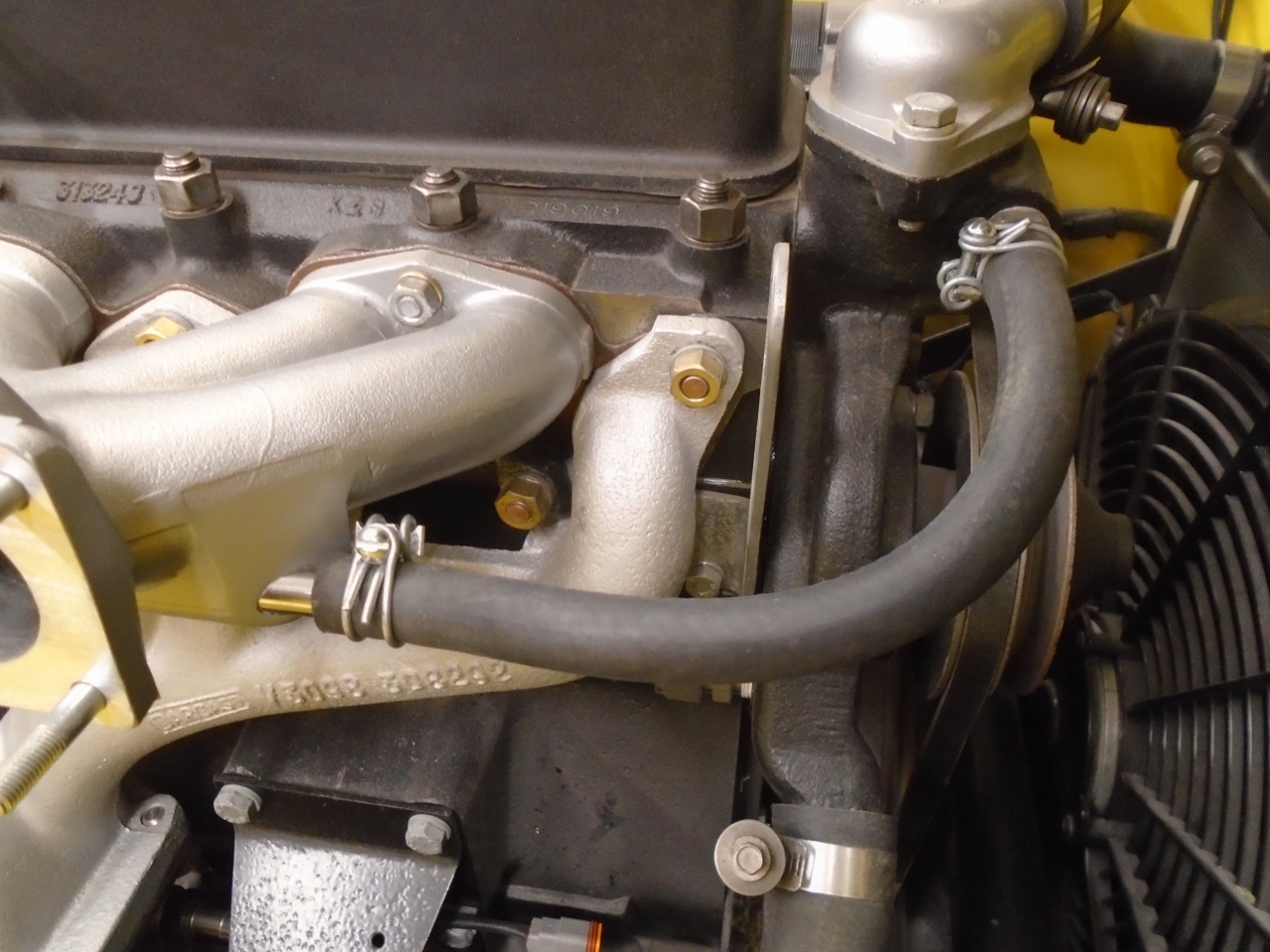
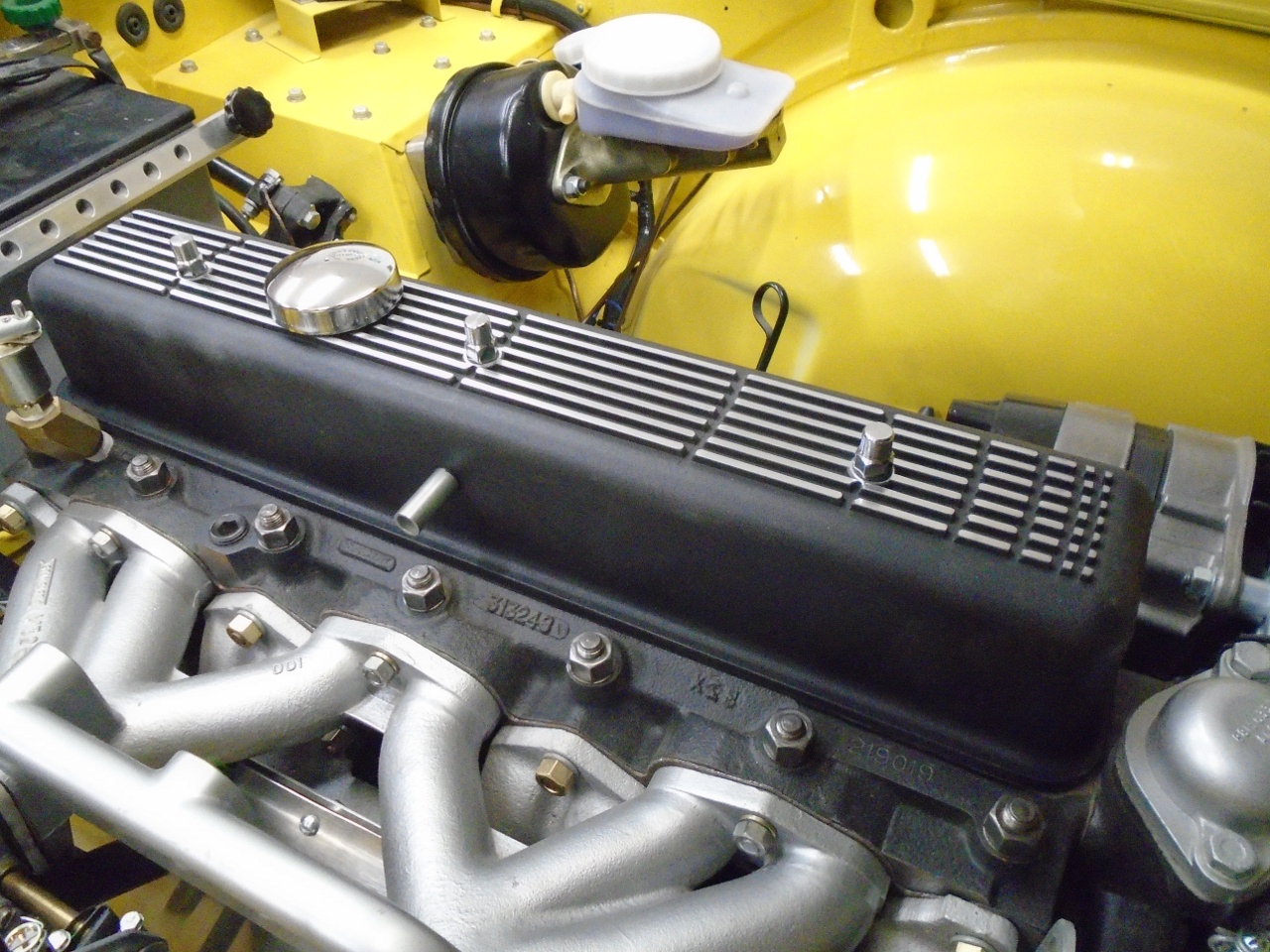
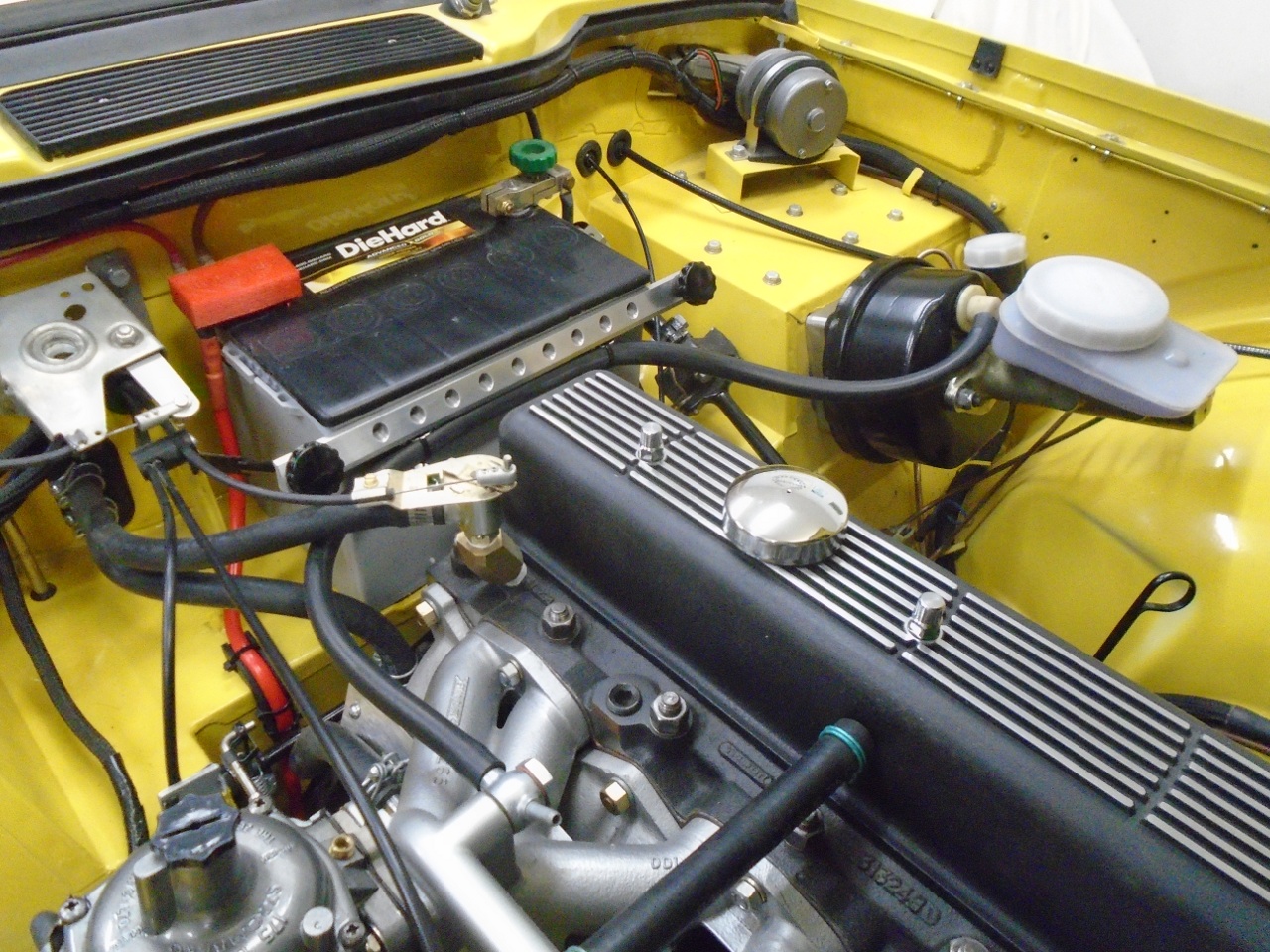
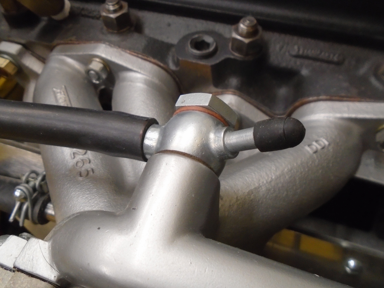
Brake Servo Vacuum Line
The
brake booster (servo) is powered by engine vacuum. A reservoir in
the booster is charged by vacuum from the intake manifold. A
little of the stored vacuum is used each time the brakes are applied,
but the maifold connection keeps the reservoir topped off. The
stock hose from the manifold to the booster ran over the top of the
valve cover. This always looked a little untidy to me. Many
people move the line to the rear of the engine, which is what I did.
It is held in place with a couple of cable ties to some small
loops on the bottom of the battery hold-down.
The extra port on the manifold fitting will be used to read the vacuum for tuning purposes. It will normally be capped.
So, this is about it for the engine bay piping and wiring.
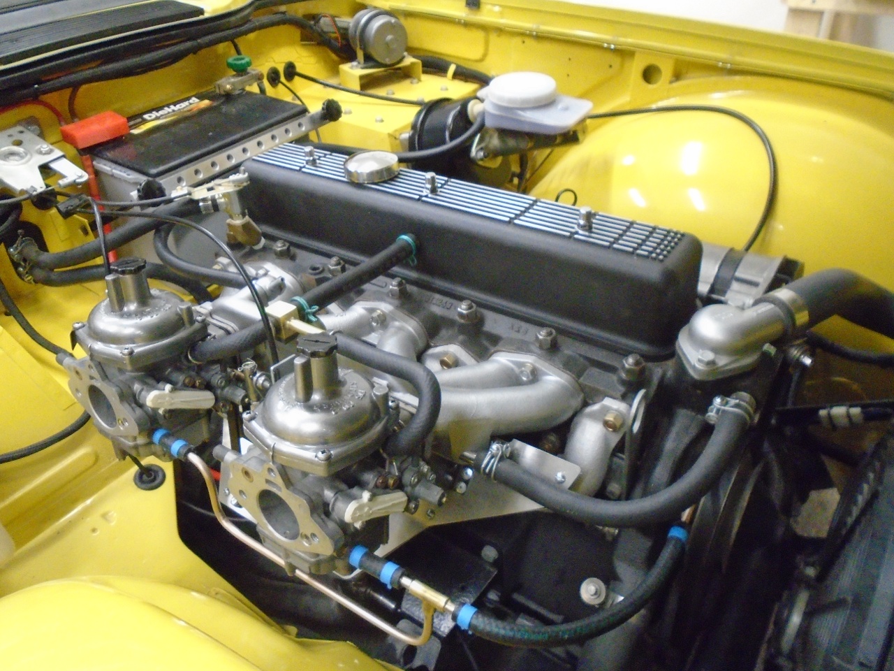
Next steps are to add fluids, spin up the oil pump, install the distributor, set static timing, and top off the battery.
Then--turn the key.
Comments to Ed at elhollin1@yahoo.com
To my other TR6 pages.