To my other GT6 Pages
September 26, 2019
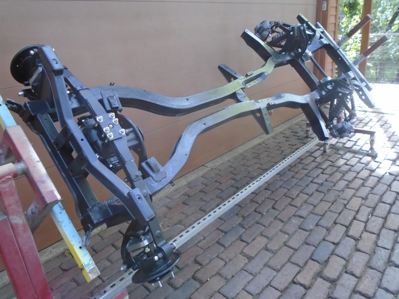
Rear Suspension
The
rear suspension in this GT6 is of the transverse leaf spring type,
where half of the cross-wise leaf spring forms the upper arm af the
two-arm arrangement on each side. The lower arm, despite its
shape, is not really an A-arm, since the apex of the "A" is at the
frame and not at the vertical link. Since neither the upper nor
the lower arms provide any significant fore/aft bracing, an
adjustable radius arm is included to provide positive location in that
direction.
Since my transverse leaf spring
was already installed, I turned to the lower arms. Both of these
had to be cut away from the frame and the vertical links.
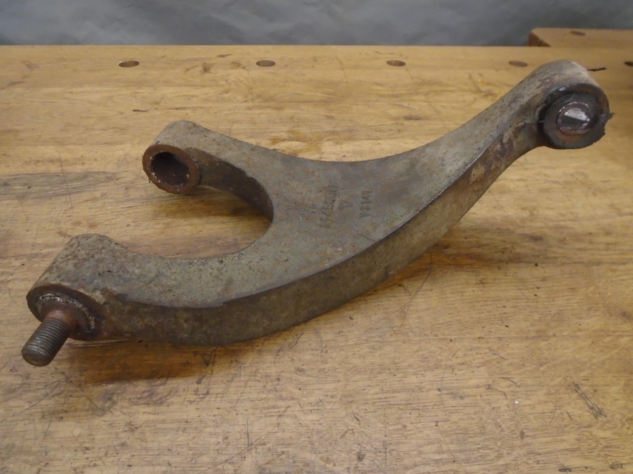
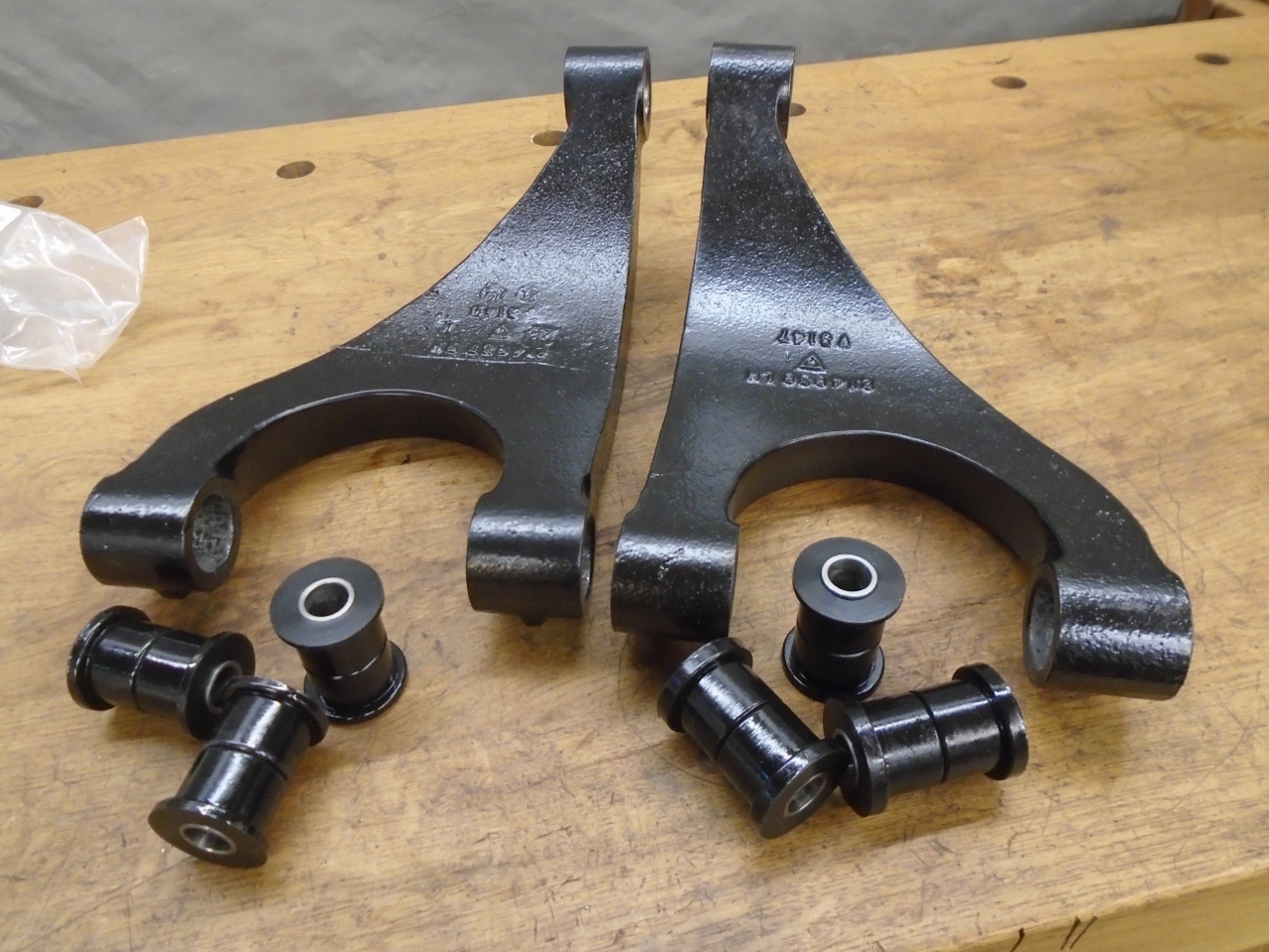
Once the remnants of the frozen fasteners and bushes were driven out, the arms cleaned up well...
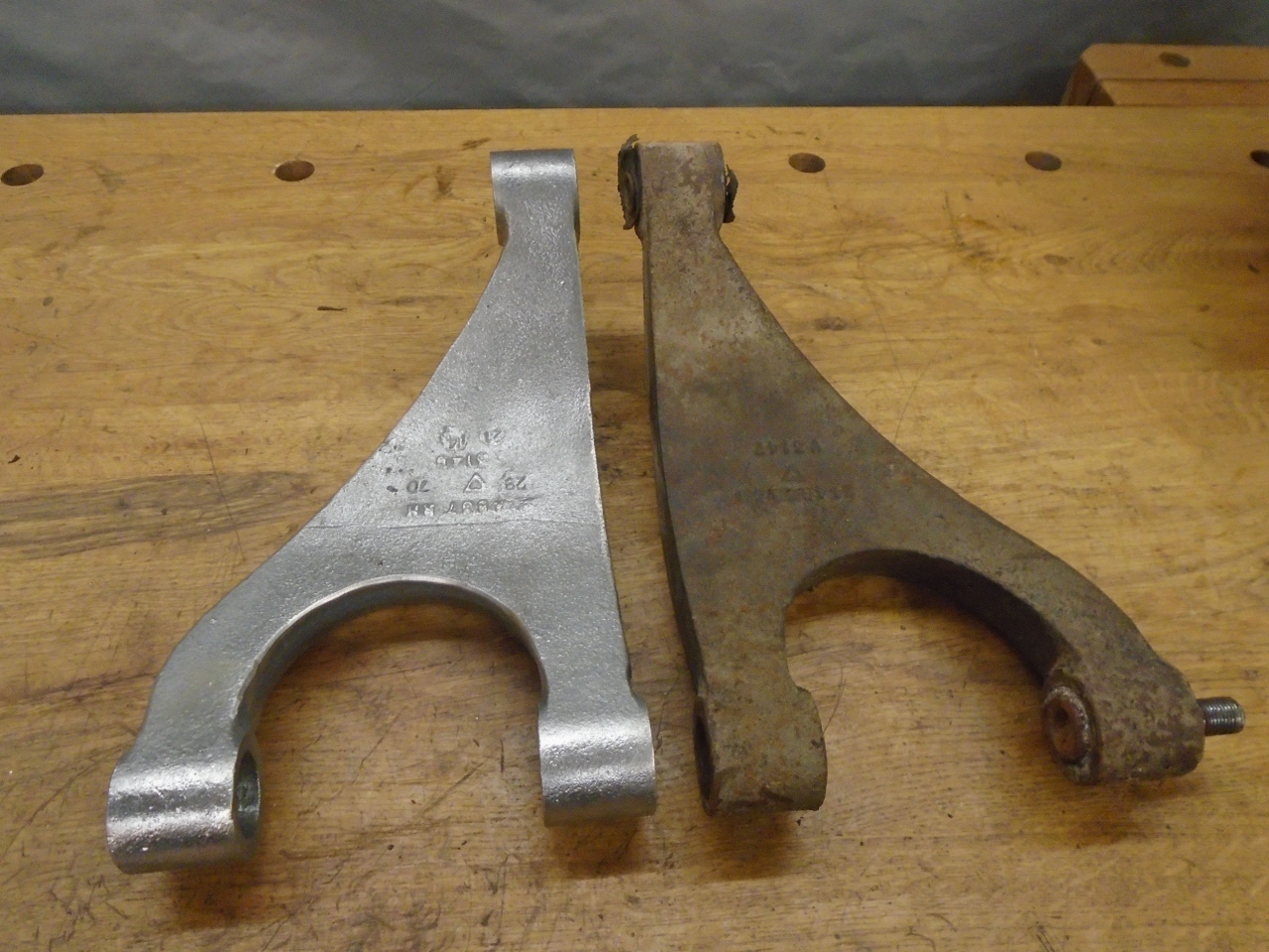
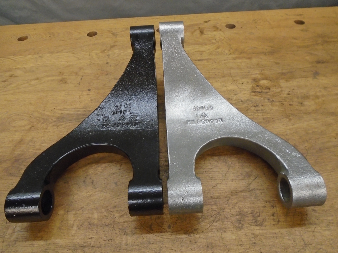
...and got a nice powder coat.
As
I was ramping up to get the rear suspension parts actually installed,
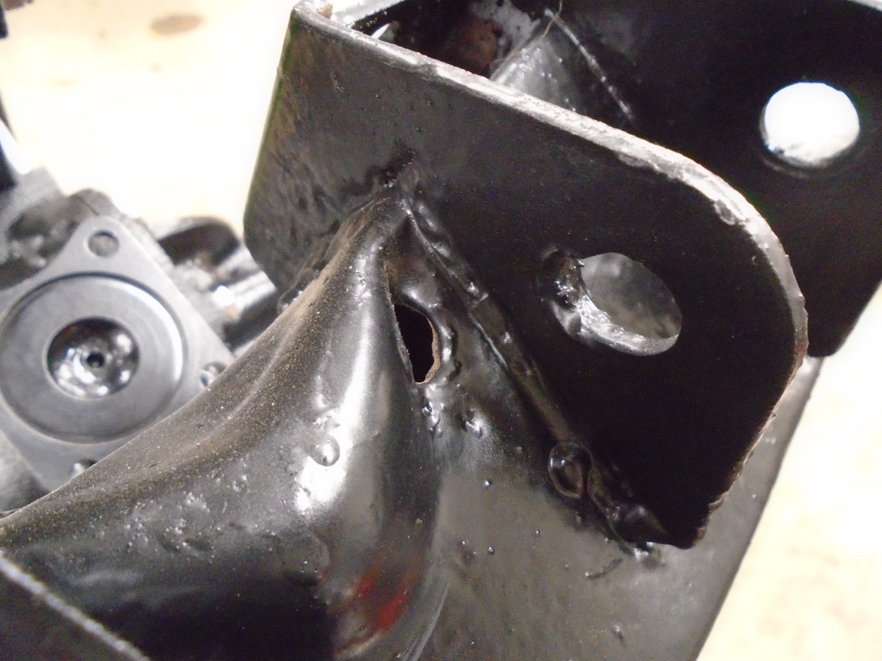
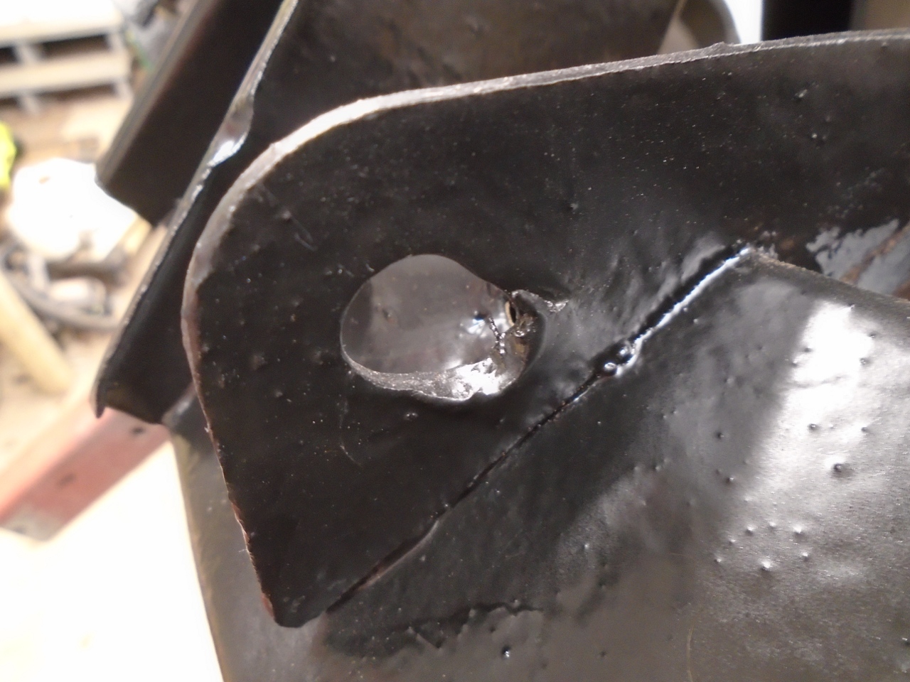
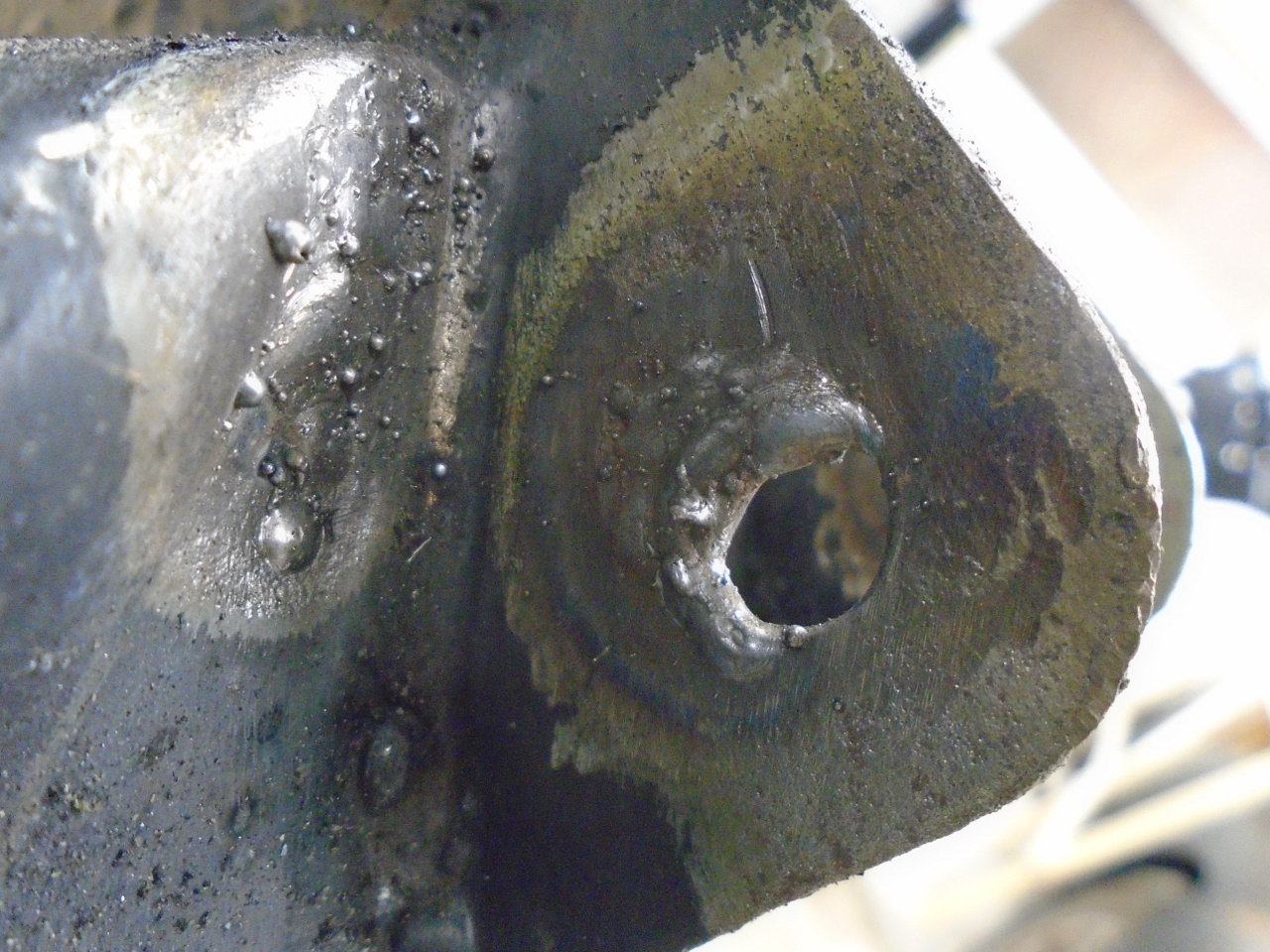
there was a small setback. When checking frame mounting brackets,
I noticed this wallowed out mounting hole. I'm not sure how this
got by me when I was prepping or painting the frame. There was
also that hole that shouldn't be there.
So I removed the paint and the upset metal from the area...
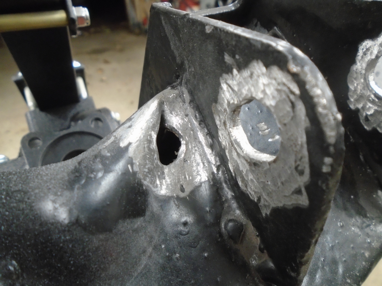
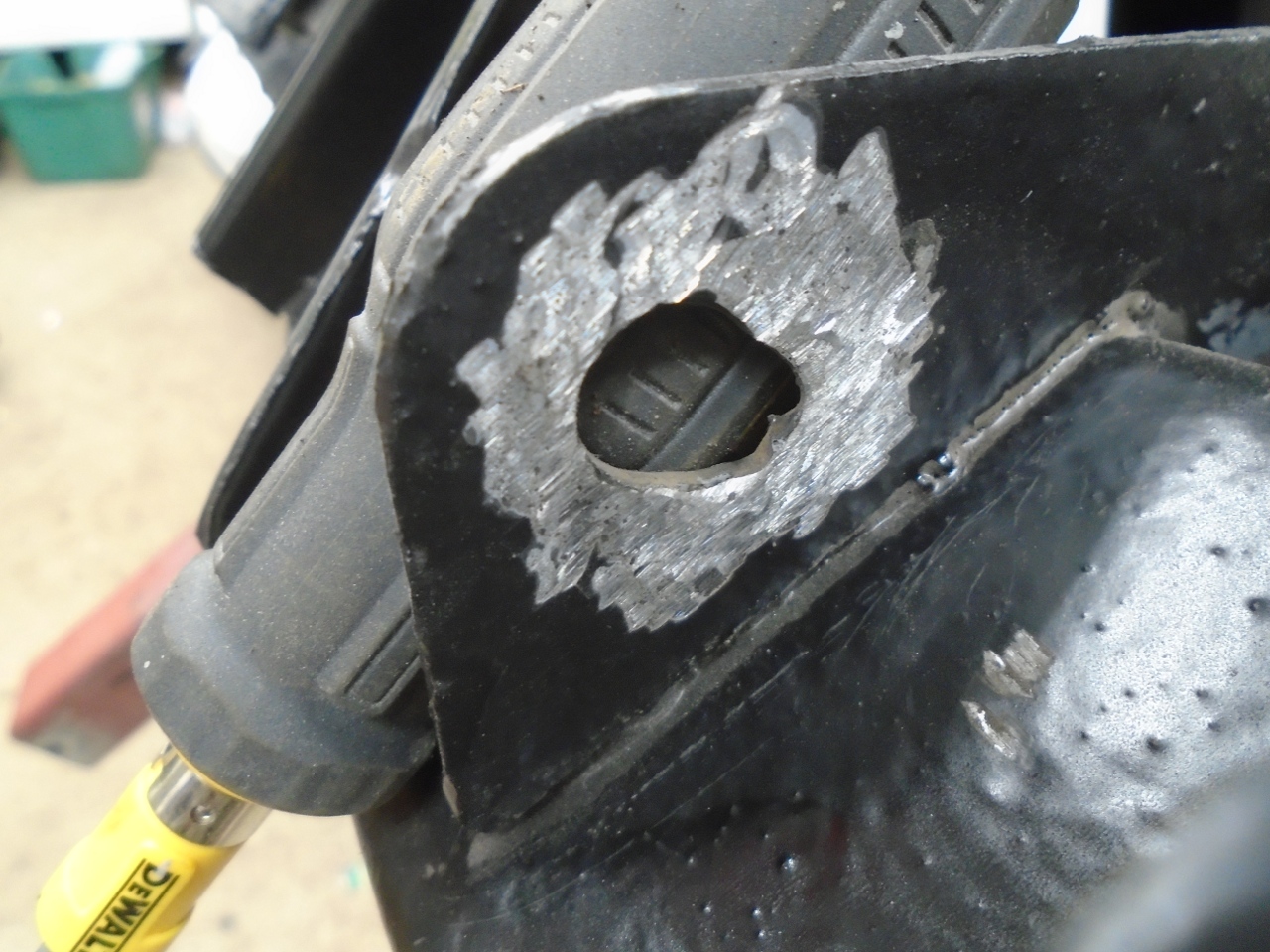
...welded it up...
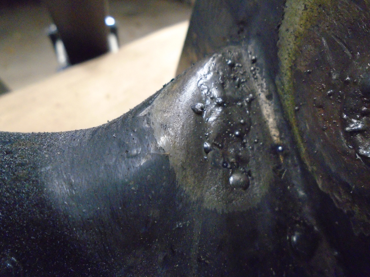
...reshaped the holes...
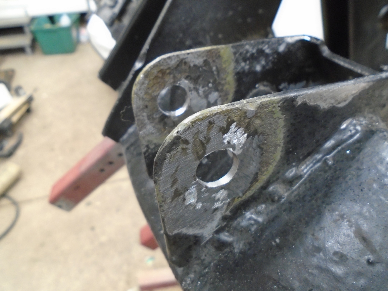
...and patched the POR15.
Now, where was I? Oh, yes, since the vertical lnks and hubs were already assembled, all that remained was to put everything together.
I hauled out the rear "trunnion" kit I ordered.
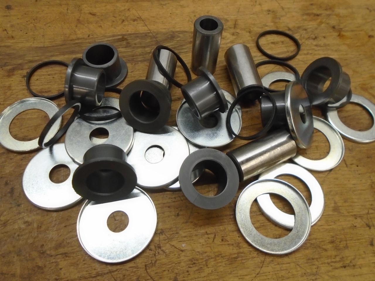
I'd
always been a little confused about these trunnion joints. It's
not that I didn't understand how to do them--I've done them a number of
times. It's more that I didn't really get why the complexity
was necessary. If it was to try to keep water out of the joint,
they don't even succeed at that very well. I didn't see why a
simpler polyurethane bushed joint as used elsewhere in the front and
rear suspensions wouldn't work just as well.
I
had decided to look into using simple bushed joints at the
vertical links when I ran across a vendor who apparently had the same
idea. They offered a rear wishbone kit that consisted of six poly
bush assemblies that did both sides of the car, so I ordered it.
Three pieces at each point as opposed to nine.
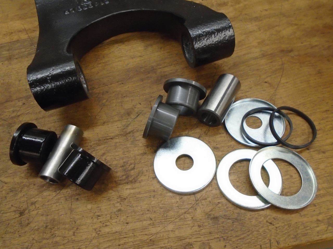
While
I am happy that a vendor is providing this option, the execution may
still need a little tweaking. The bushes at the vertical link fit
perfectly. The bushes for connection to the frame bracket were
slightly longer, but unfortunately, the internal distance tubes were
not.
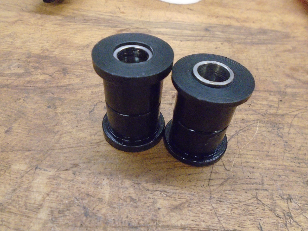
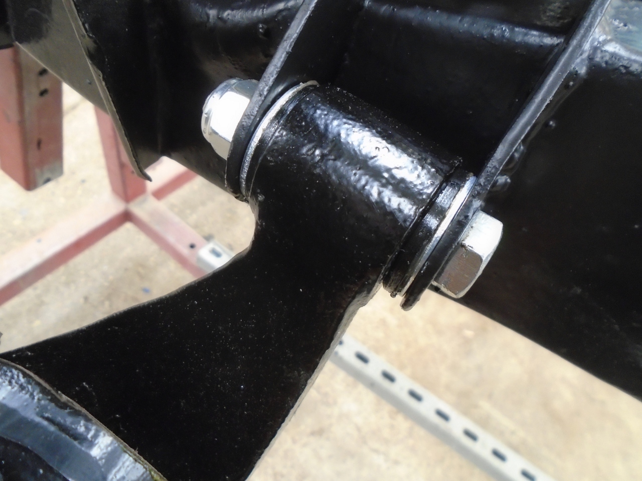
My
understanding of the way these joints work is that the distance tube
should be clamped rigidly in the bracket by the mounting bolt, leaving
a small clearance for the bushes to rotate on the tube. I
considered making new tubes, but in the end, I just trimmed the bushes
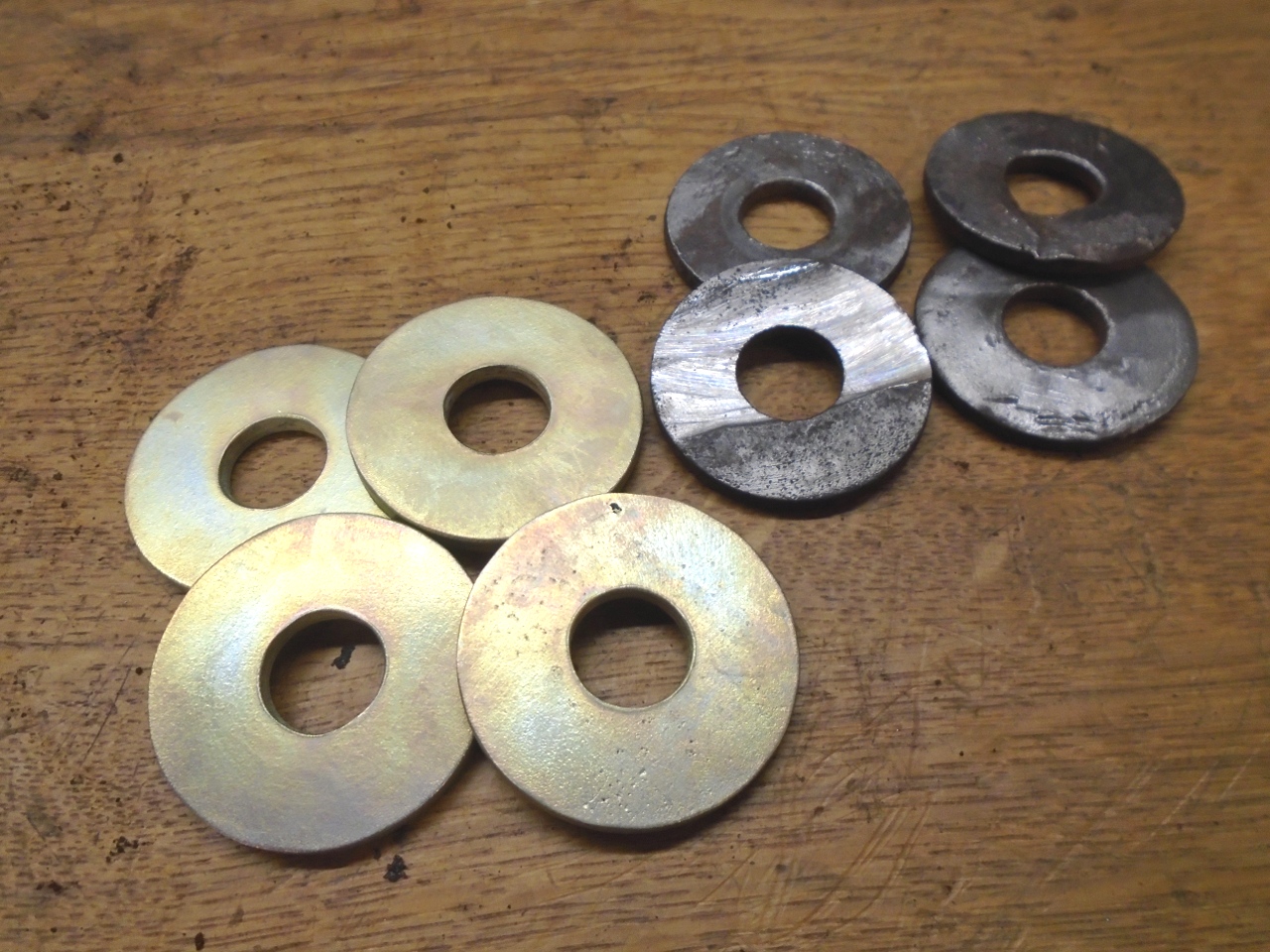
a little shorter. This then required a thin washer on either side
of the bush to make up the difference.
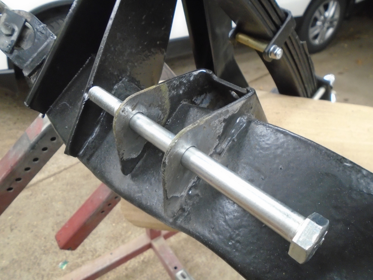
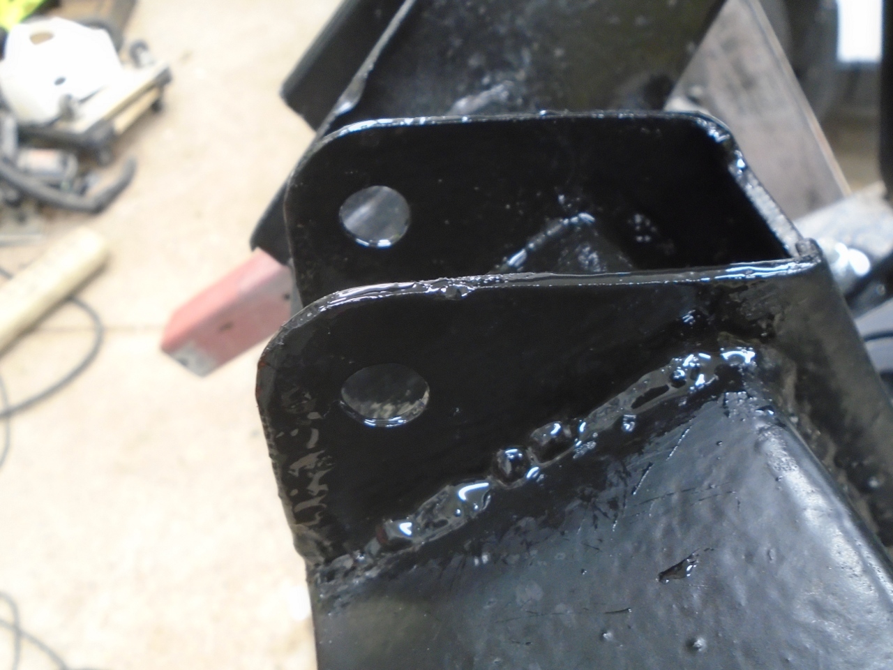
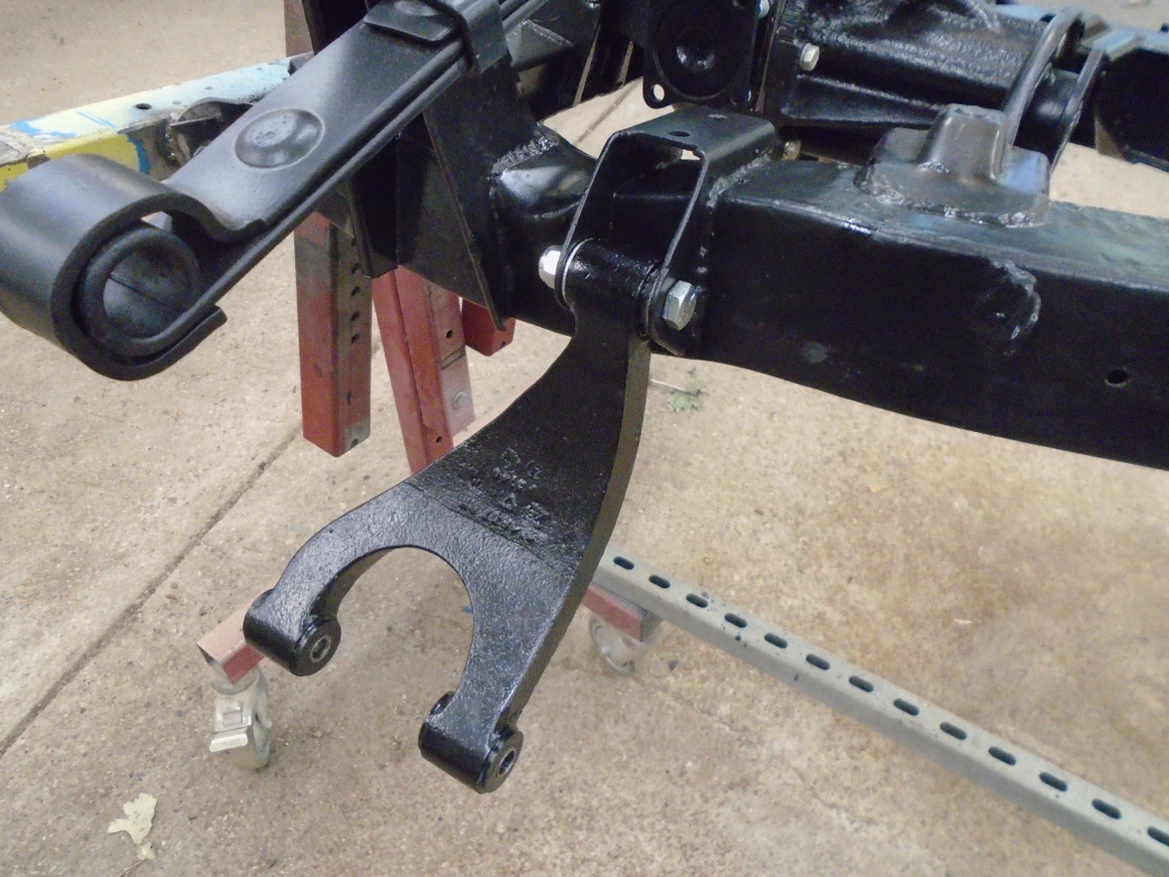
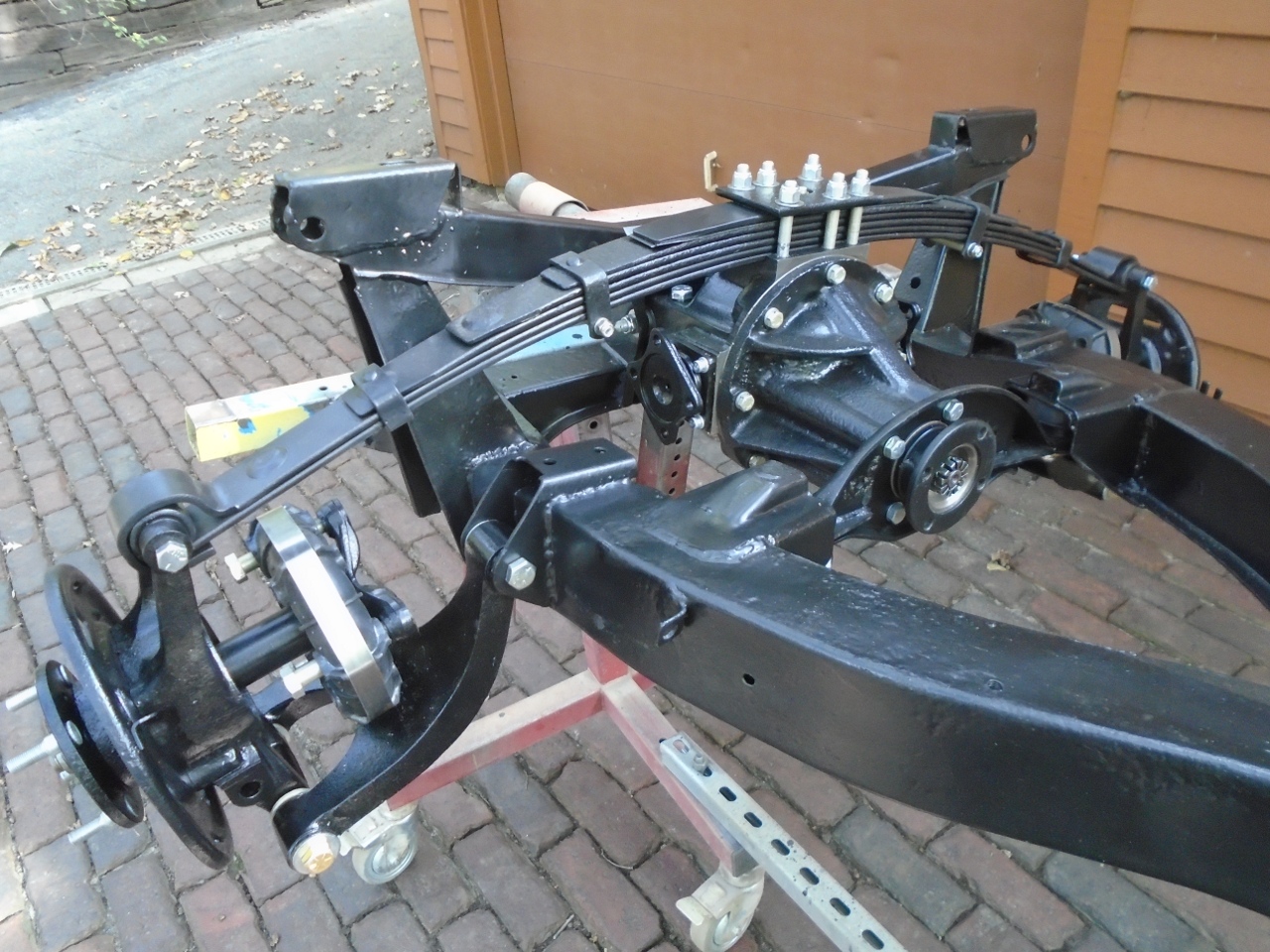
The
arms went home fine. The spacer washers are visible. The
arms rotate smoothly, with just the right amount of drag.
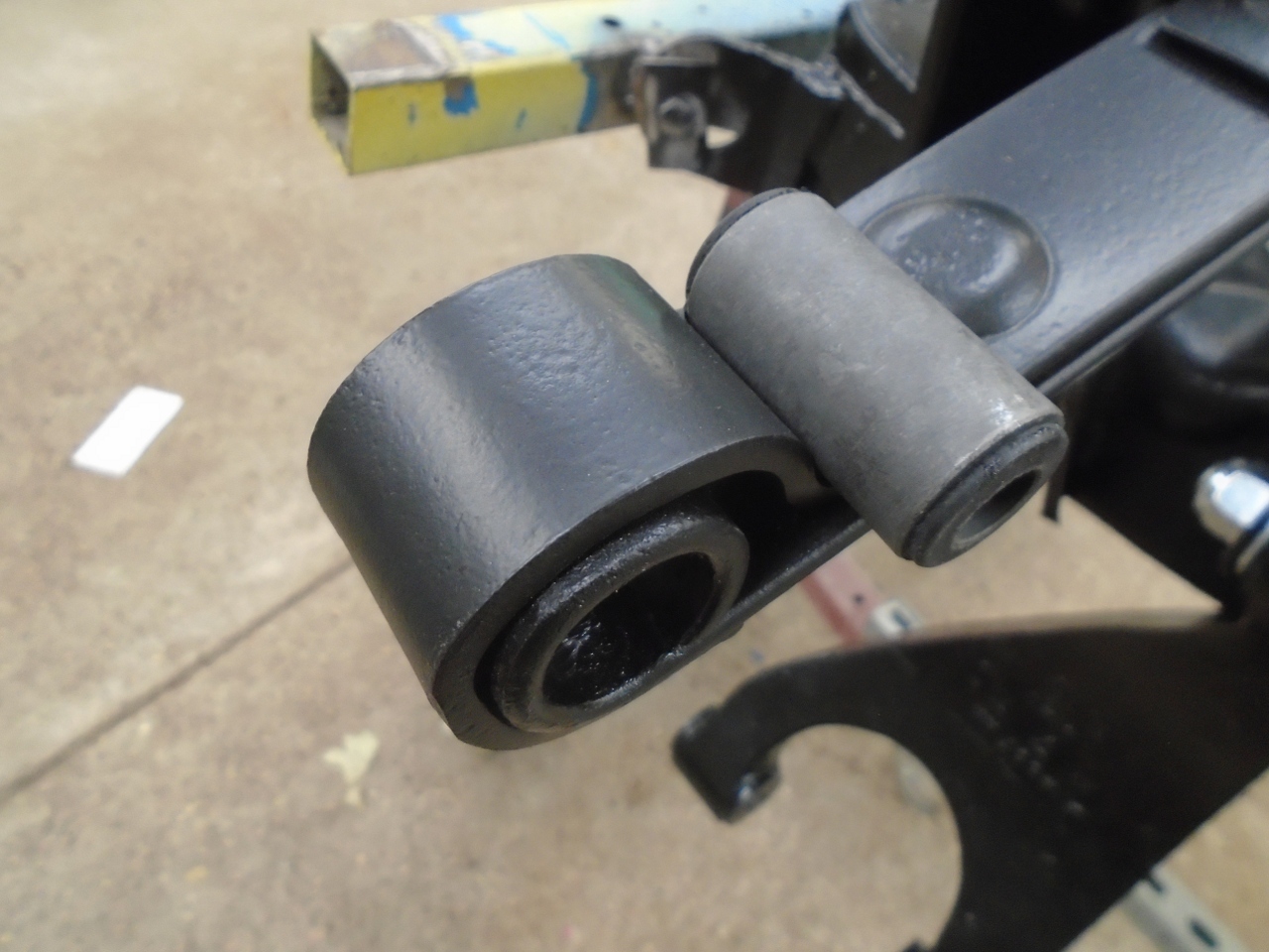
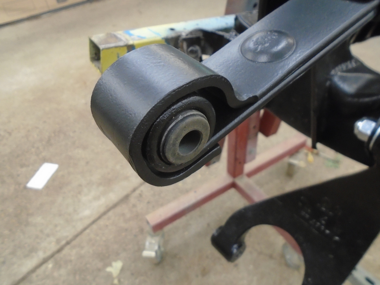
In
preparation fot the vertical link, the bushes had to be driven into the
spring eyes. I'm not sure why I didn't get poly bushes for these,
but I didn't. That means I'll have to wait until the suspension
is loaded to tighten the bolts in these bushes.
I
brought the vertical links up from the shop. It seemed easier to
hang the links from the spring eyes first, so that's what I did.
That way the weight of the vertical link assembly was supported
while I fiddled with the trunnion connection.
I
was a little confused by a massive 1/4" gap between the fingers of the
lower arm and the bottom of the vertical link. There was
obviously a part missing. I checked several of the vendors' parts
blowups, and saw nothing. I finally checked some of the pics I
took on disassembly, and saw that there was a pair of thick washers,
one at either end of the bore at the bottom ov the vertical link.
The parts blow-ups don't show them, but I managed to find mine (I
don't throw away anything
until the job is completely done.) They were pretty beat up,
including damage from the saw I had to use to get things apart. I
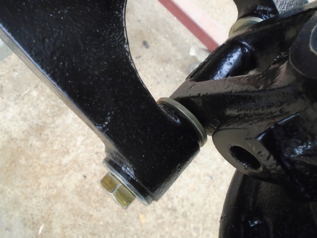
ended up making the washers (spacers, actually) that actually fit better than the originals.
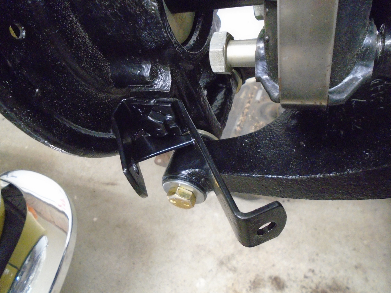
Here is the lower connection of the vertical link. The spacer washer is visible.
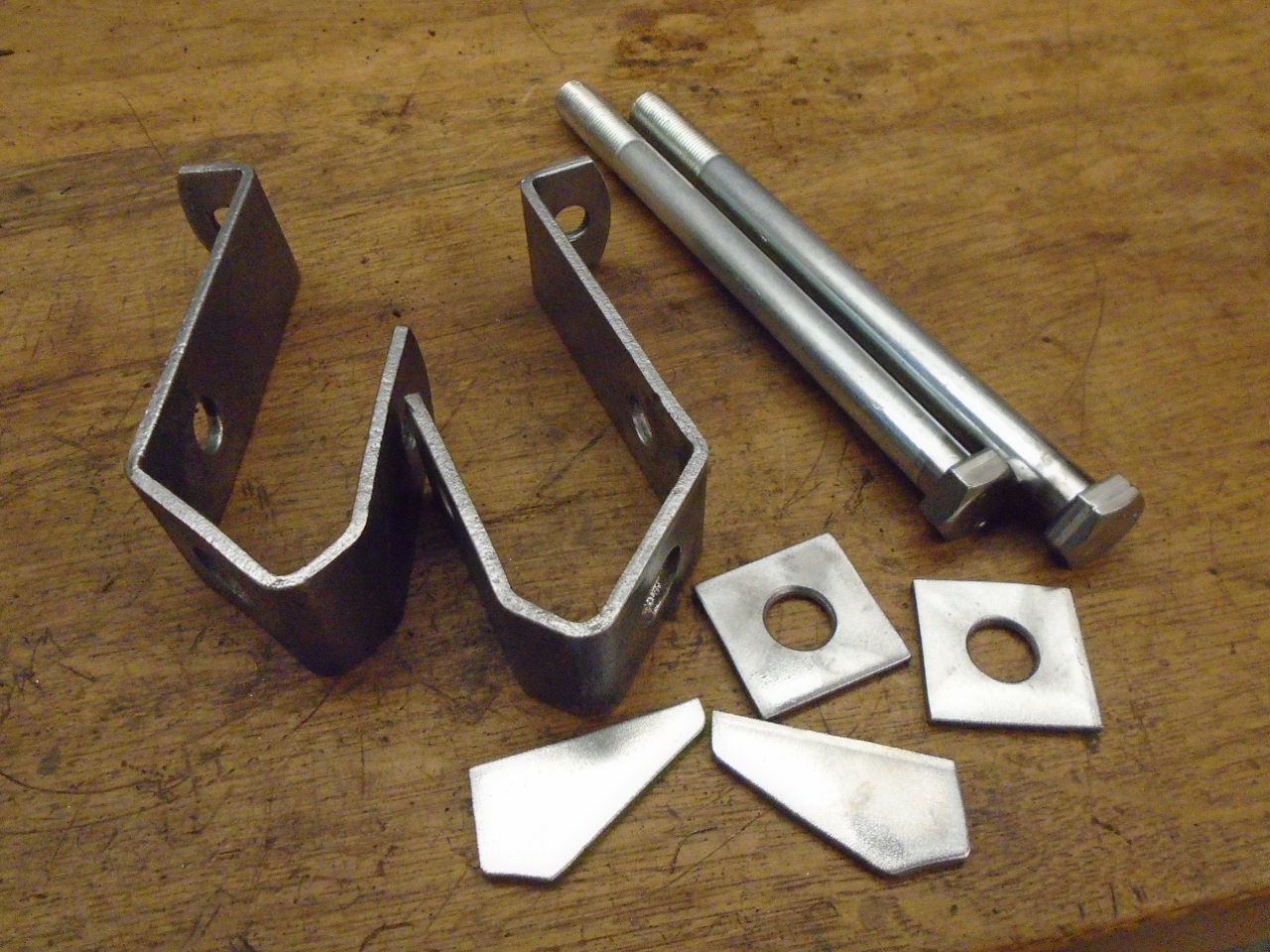
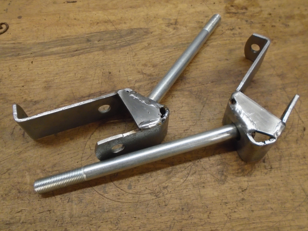
There
was only one last detail for the suspension. There is a long bolt
that goes through the vertical link that holds the lower end of the
damper on one end, and a bracket for the radius arm on the other.
That bolt was frozen in both of my vertical links, and had to be
drilled out. On both sides, I was able to save most of the radius
arm bracket. The original bolts were actually welded to the
brackets. Here are the original brackets, new bolts, and
replacement for the pads and strengtheners I had to sacrifice in the
demolition.
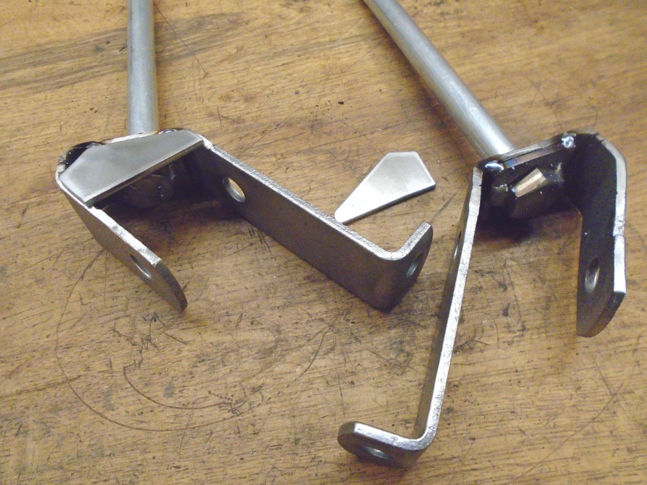
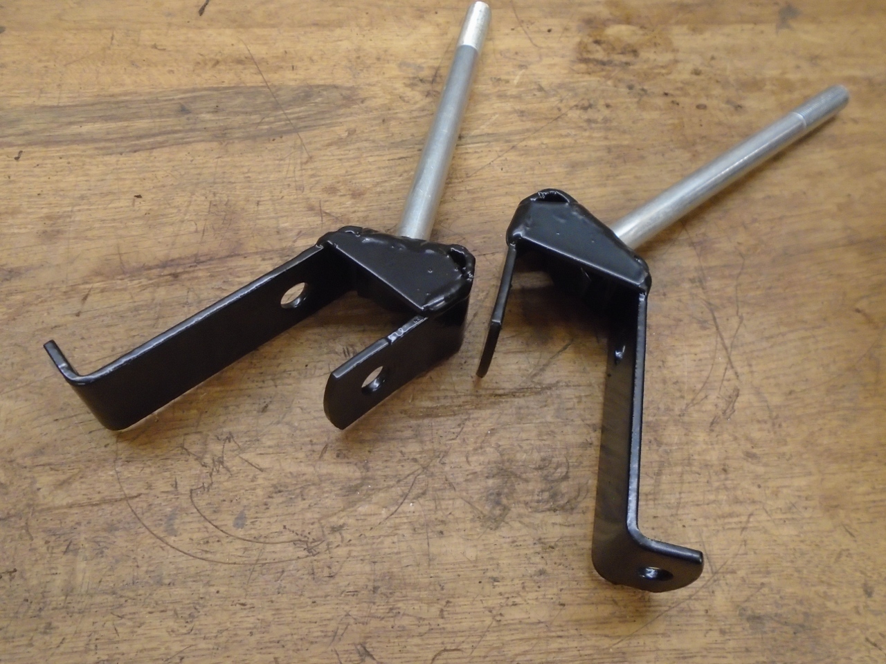
The
heads of the bolts get welded to the square pads, the pads welded into
the brackets, and then the strengtheners welded on. Then the
bracket end is powder coated.
Since
both the radius arms and the dampers connect to the body, they have to
wait, and these assemblies have nothing to do right now. But I'll
put them in place so they don't walk off. I don't think anyone sells these.
The
frame is nearly to the point where I can put the wheels on and get it
off the rotisserie. Putting the axles in will be easier with the
chassis on the ground.
I
had read warnings about how difficult this part of the project might
be. I'll have to say, I didn't see it. Actual assembly only
took maybe an hour or less. Cost was just for the bushing kits,
which I effectively bought twice.
Now, on to rear brakes.
Comments to Ed at elhollin1@yahoo.com
To my other GT6 Pages