To my other GT6 pages
September 22, 2019
Rear Hubs
GT6
cars used more than one kind of rear axle design over its model life.
For at least the 1969 model year, it used the so-called
"Rotoflex" axle. Paired with a conventional universal joint at
the inboard end of each half axle was a rubber donut at the outboard
end. This Rotoflex coupling performed the same job as a U joint,
but with some resilience in the power transmission. Rotoflex
type joints were apparently used in a number of other cars of the era,
including some Lotus, Porsche, Mercedes, and Alfa Romeo cars.
The
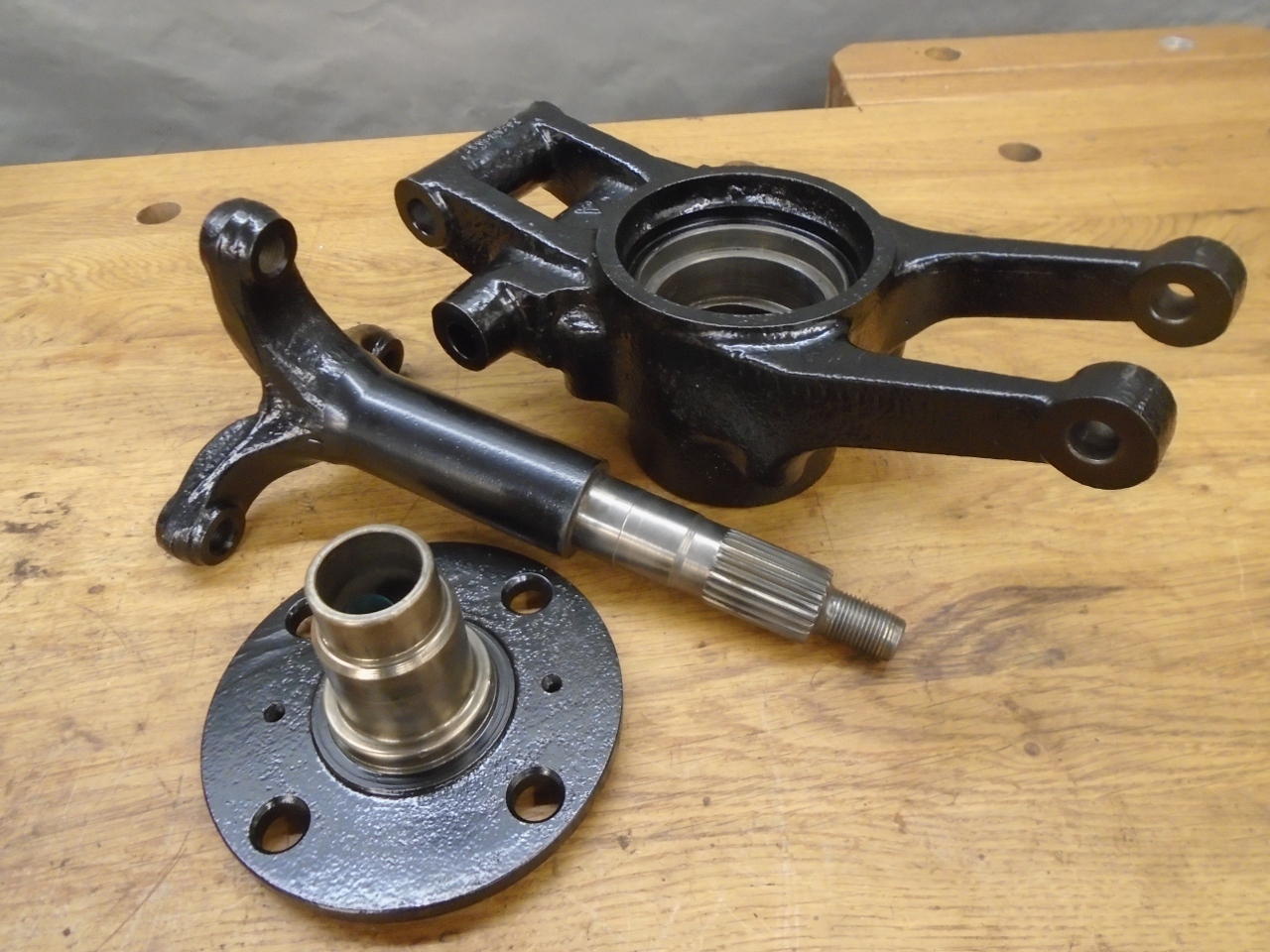
hub arrangement I found on my car was unique to the Rotoflex axles,
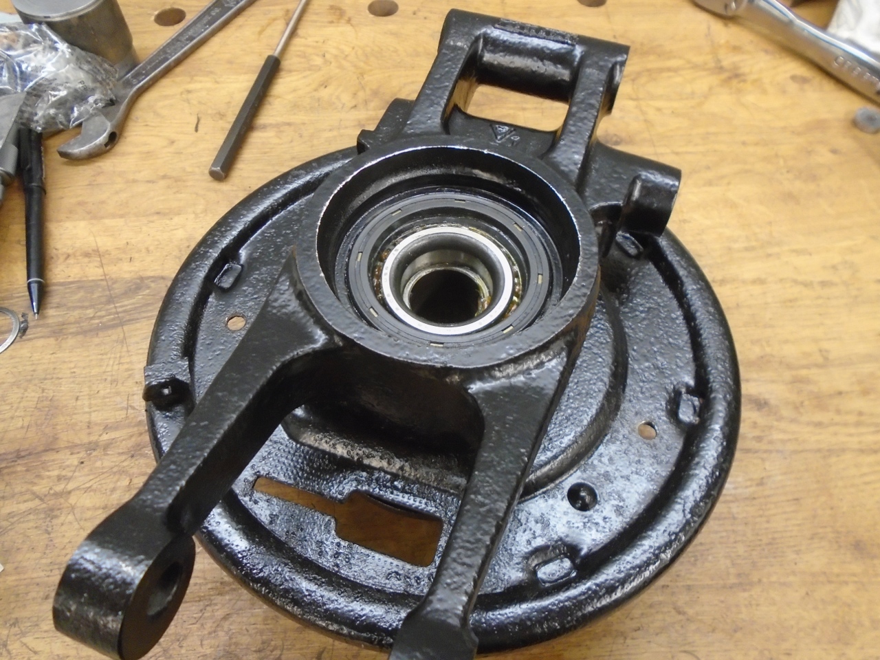
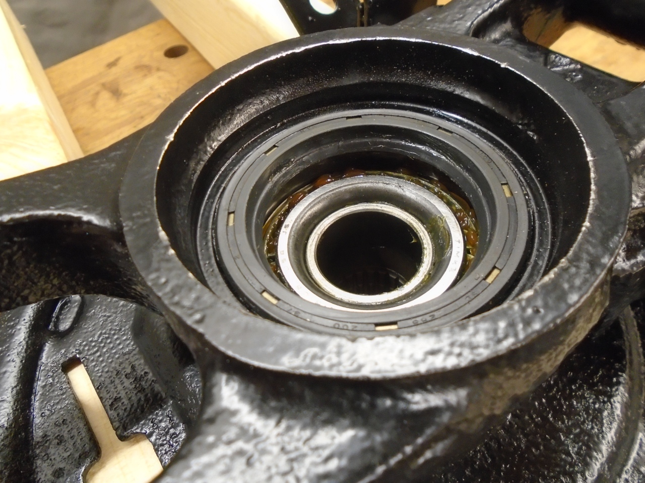
and I was a little confused by it at first. It is pretty
ordinary in that it uses opposed tapered roller bearings, but the
bearings are housed in the vertical link instead of in the hub itself.
Also, instead of setting bearing clearance with a distance tube
and shims like some other cars, the shims go between the outer axle
shaft and the nose of the hub. Once I understood how it went
together, it made sense, but I considered the assembly a little tricky.
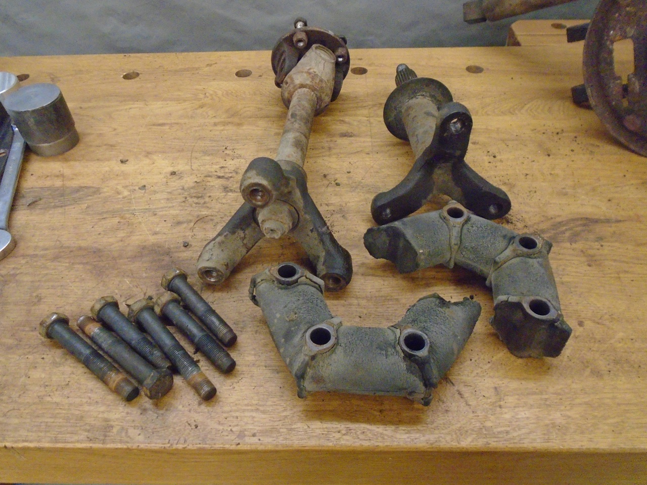
I brought this rusty pile down to the shop. Most of it had to be cut away from the frame.
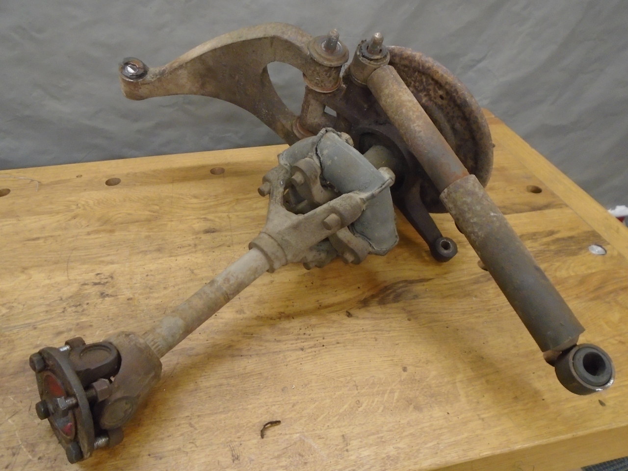
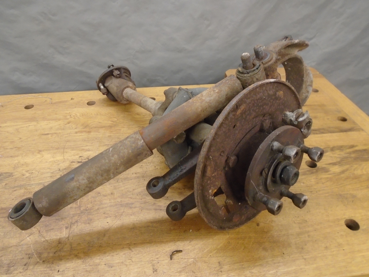
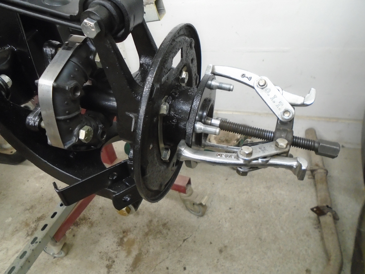
One
good thing about the Rotoflex axles is that they do not use taper
joints at the hubs. This makes them easier (but still not
necessarily easy) to disassemble just using a hub puller. The hub
is driven by a spline on the outer axle shaft.
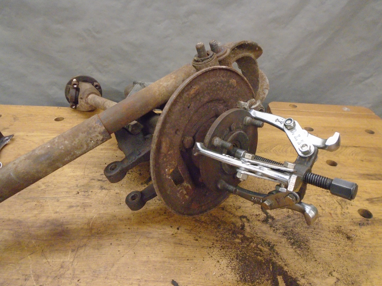

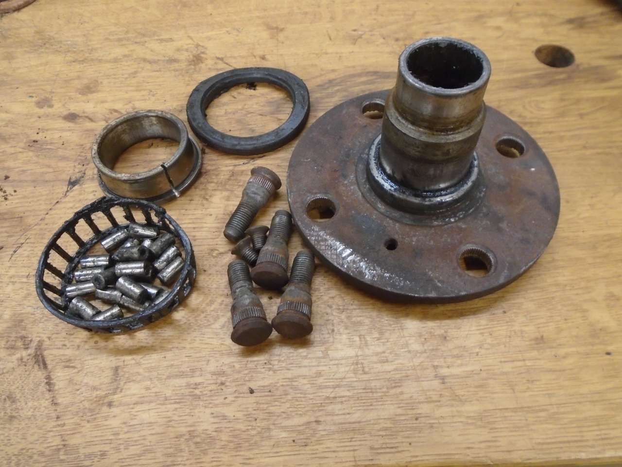
The hub itself is then driven out of the inner bearing.
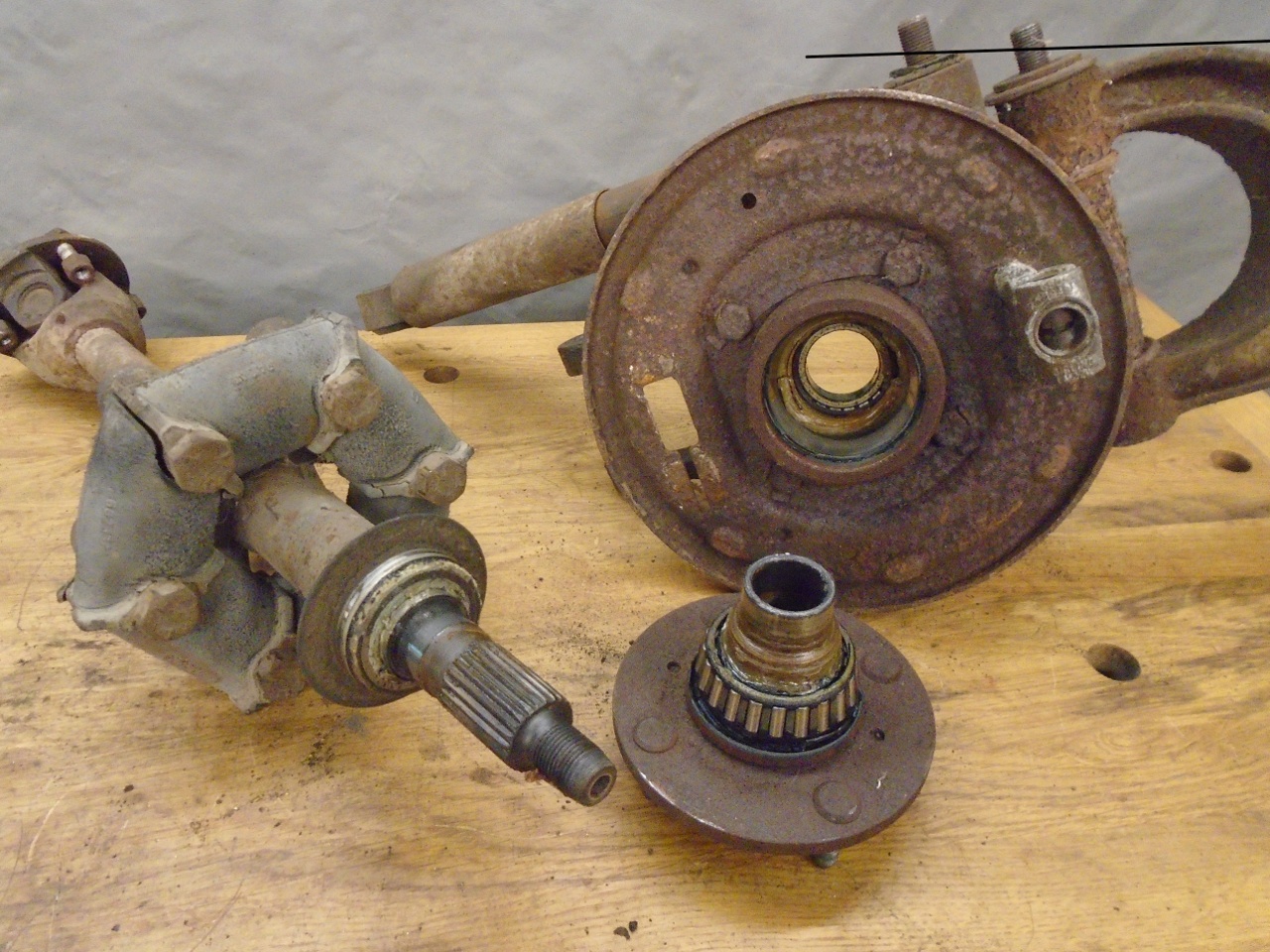
One of the 50-year old Rotoflex joints fell apart when released from the axle.
In an act of wanton defiance, the hub made me destroy the bearing to get it off.
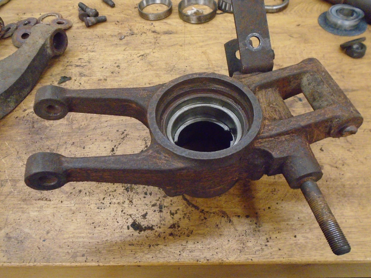
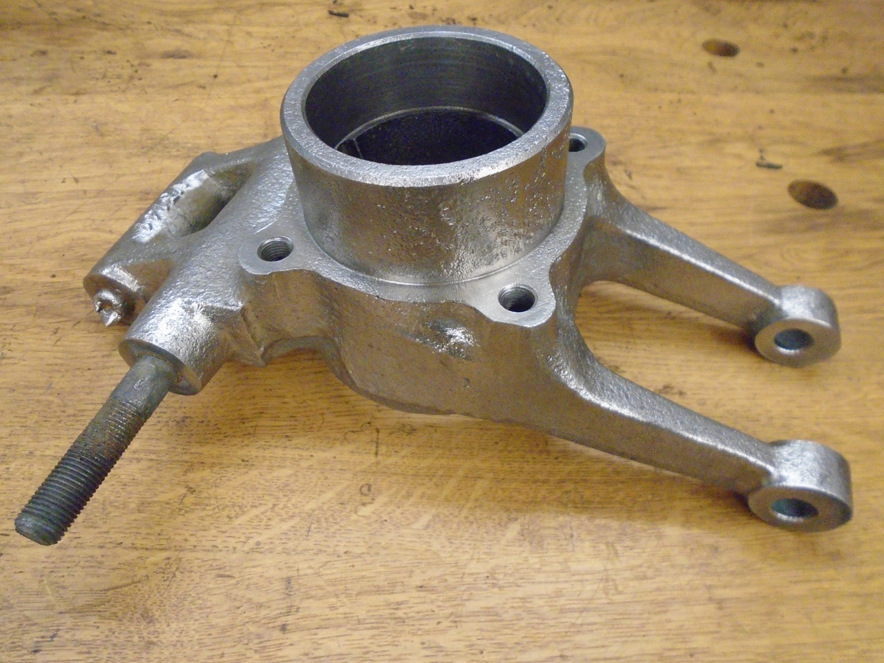
But I had bigger troubles with the vertical link.
The
long bolt that holds the radius link bracket on one end, and the bottom
of the tube shock on the other, was seized in place. I tried
copious amounts of heat, violence, and swearing to no avail.
Besides that, the bolt that once attached the link to the lower
suspension arm was broken off on one side, and had to be cut off on the
other.
With some surgery, I did manage to get the radius arm bracket off, but this didn't really help with the bolt itself.
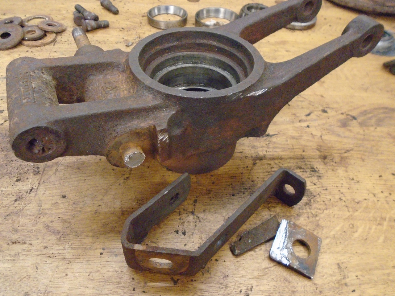
Degreasing and derusting also didn't help the situation, but they made the piece more pleasant to handle.

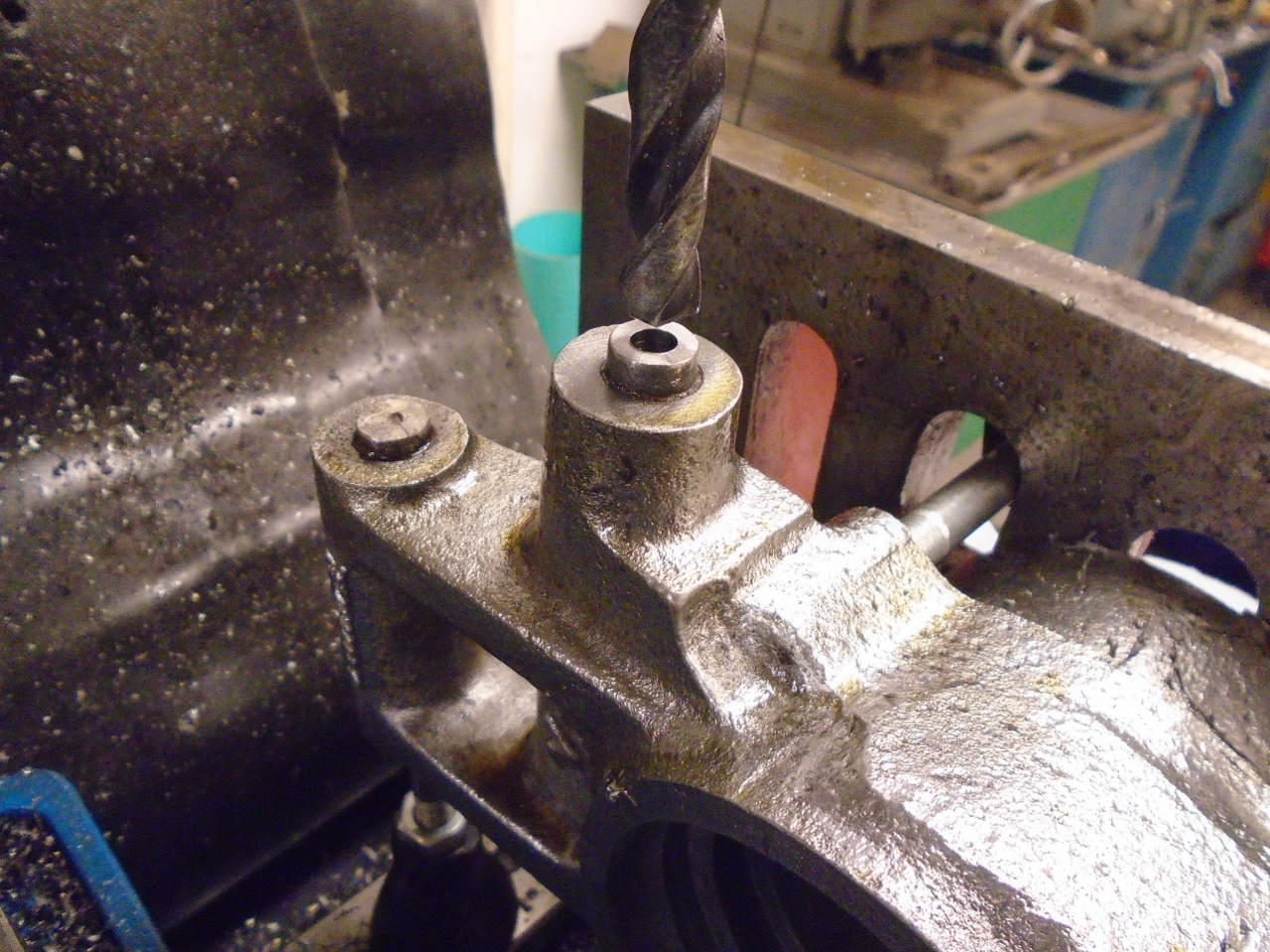
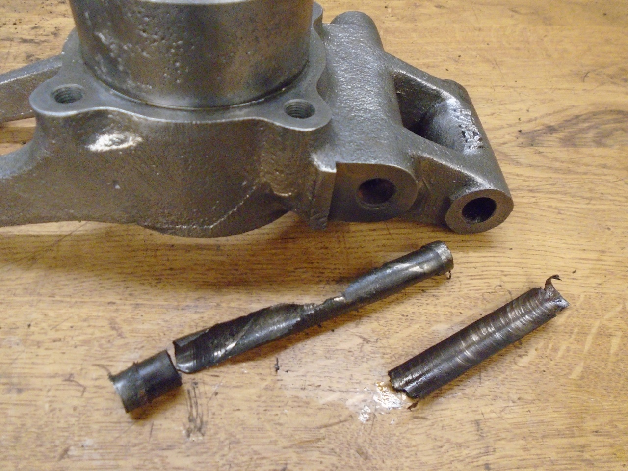
Drilling
out the bolts worked fine but, being fairly long, getting the drill's
trajectory on target was a little fiddly. I went as deep as a
1/4" drill would go, then finished with a 31/64". They
were 1/2" bolts. They finally gave up.
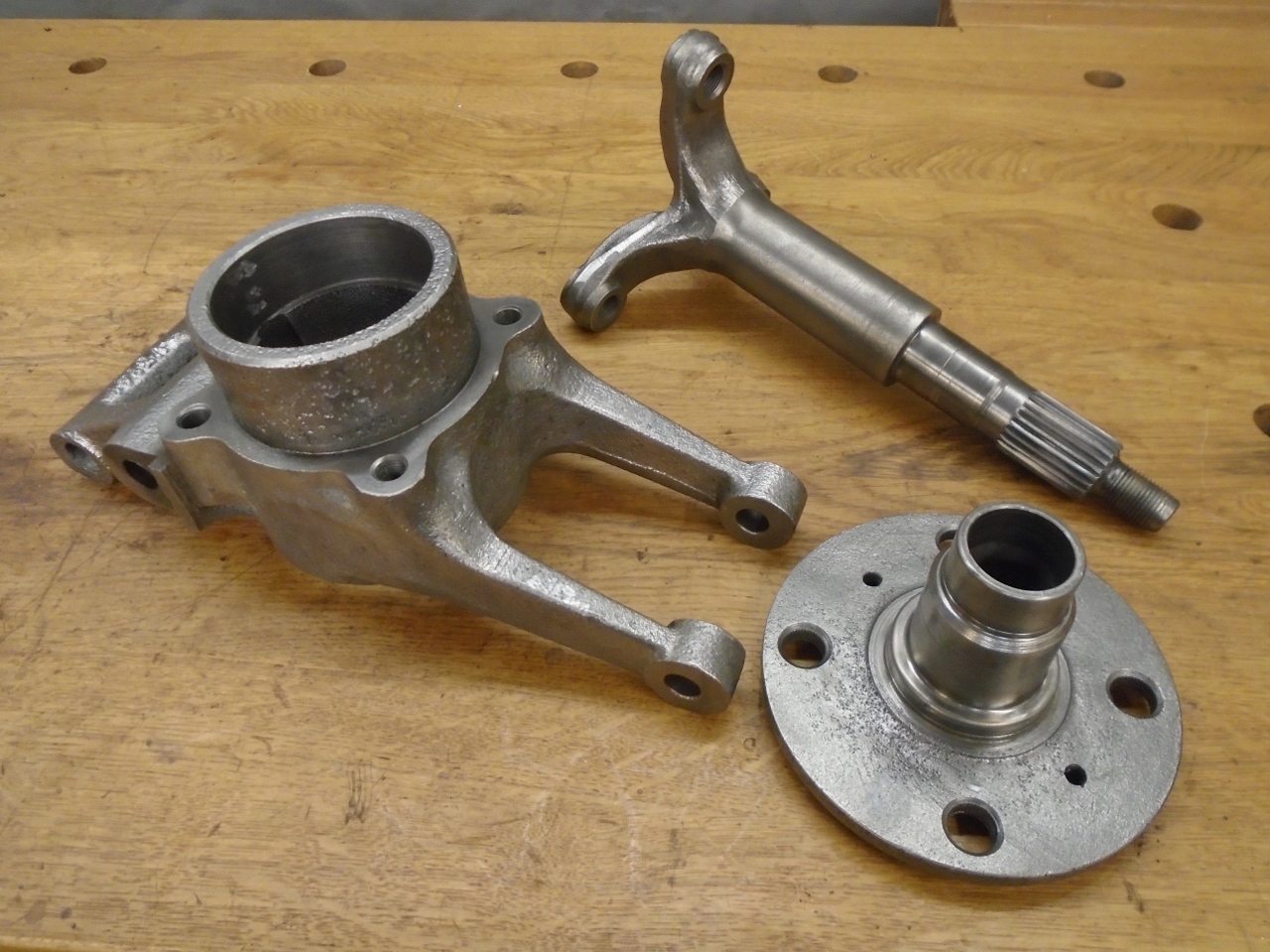
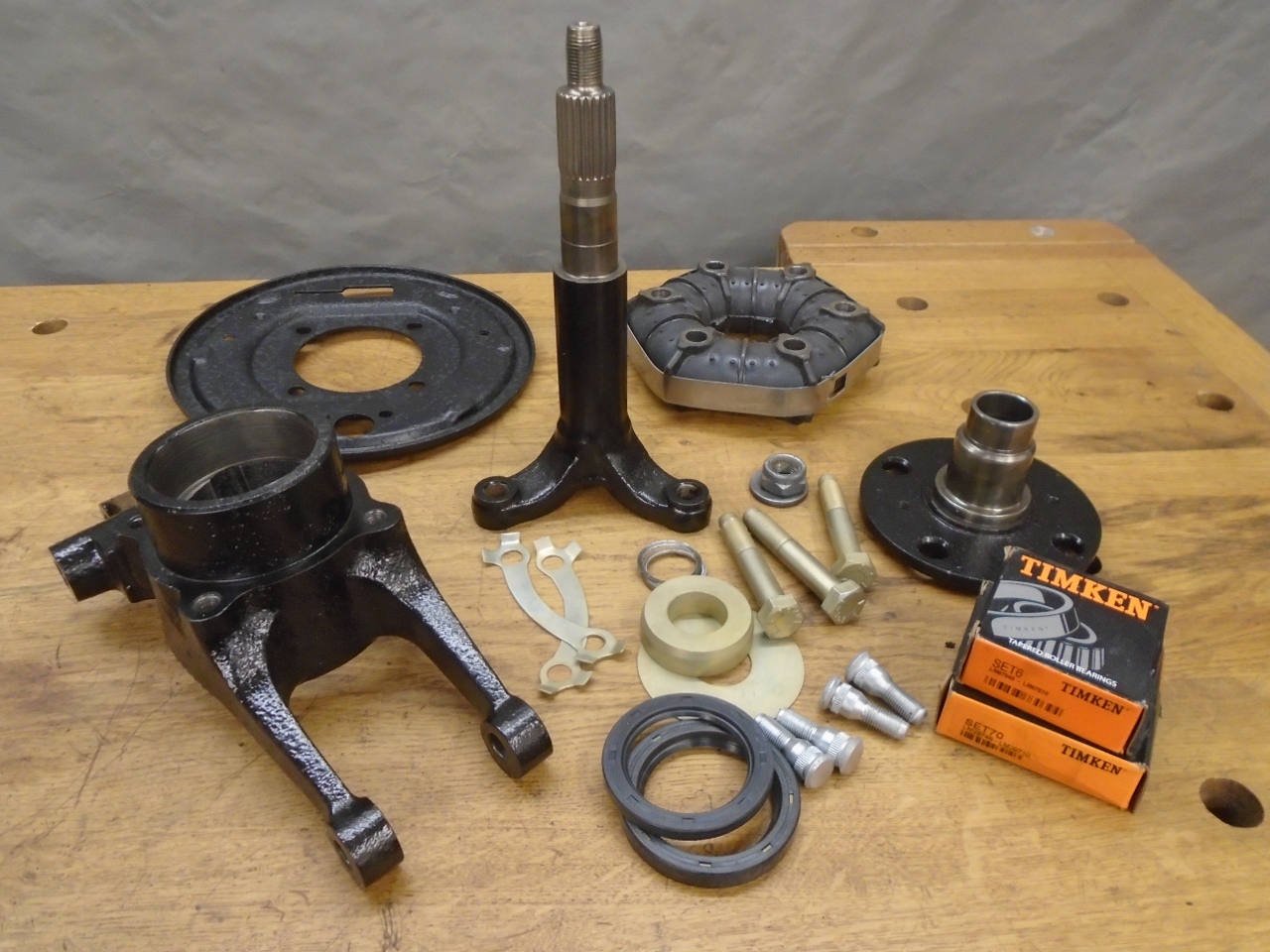
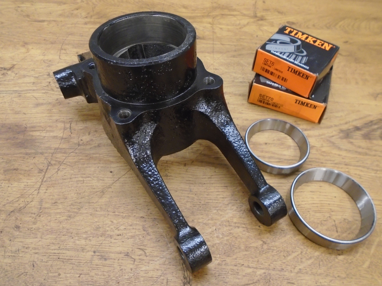
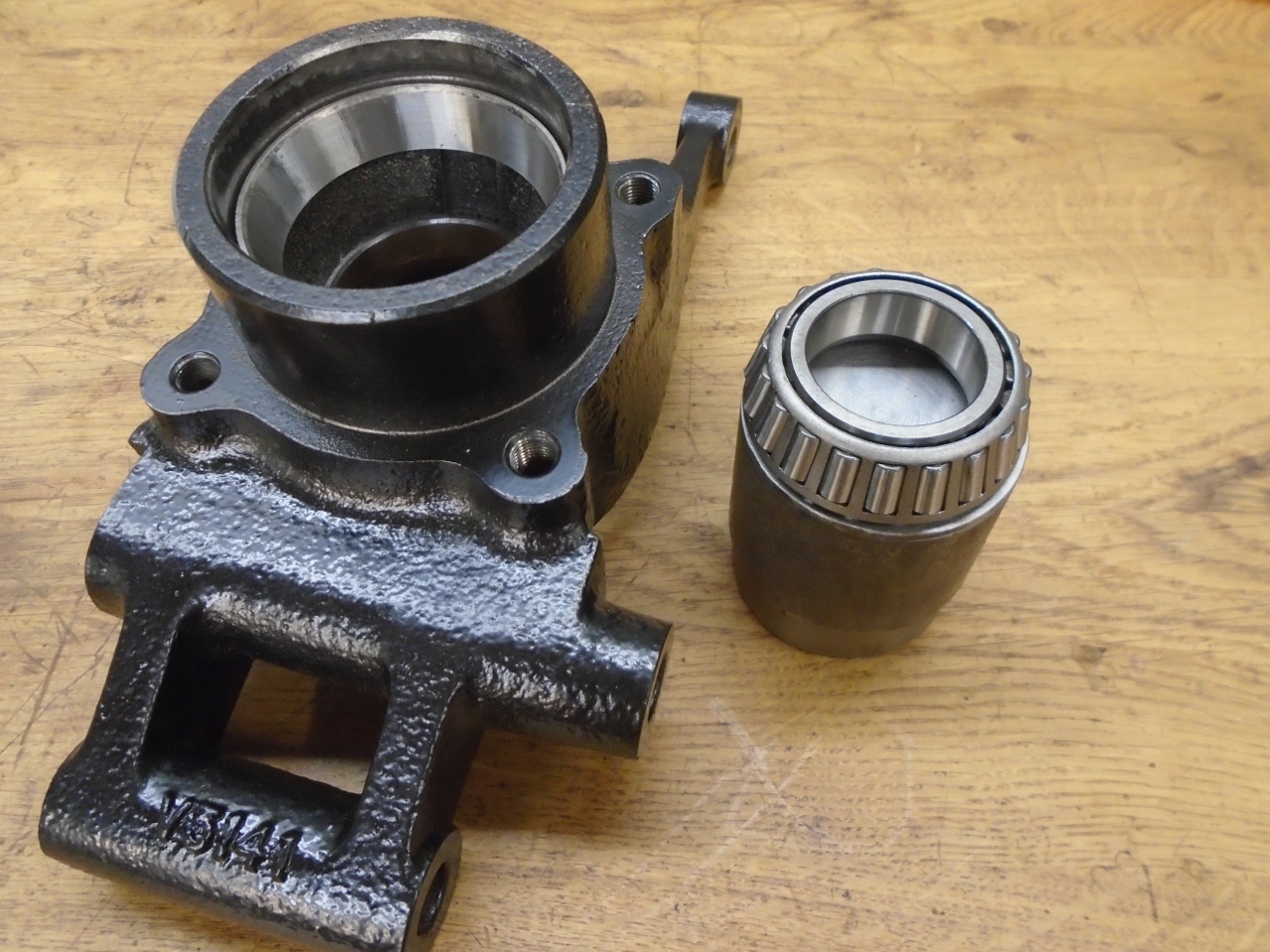
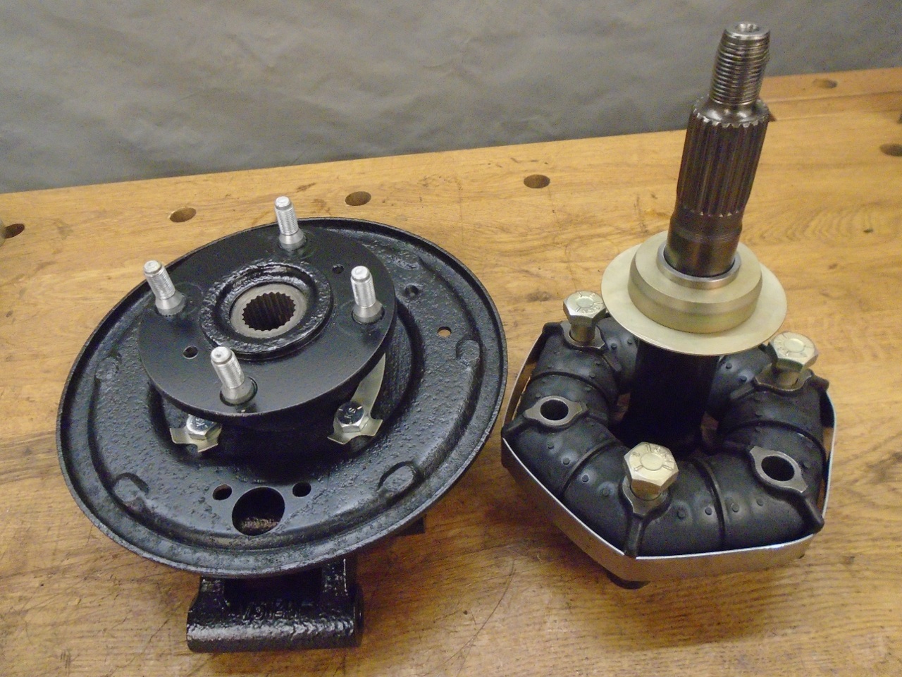
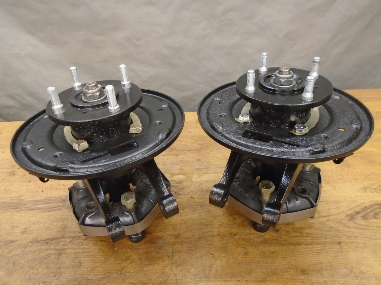
So here are the three main pieces of the hub/vertical link assembly, raw, then powder coated.
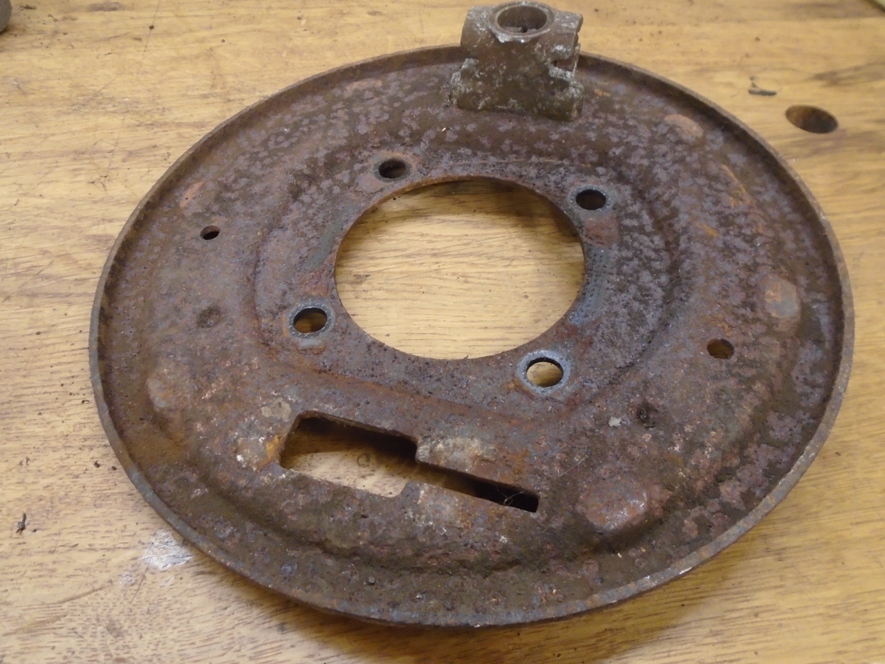
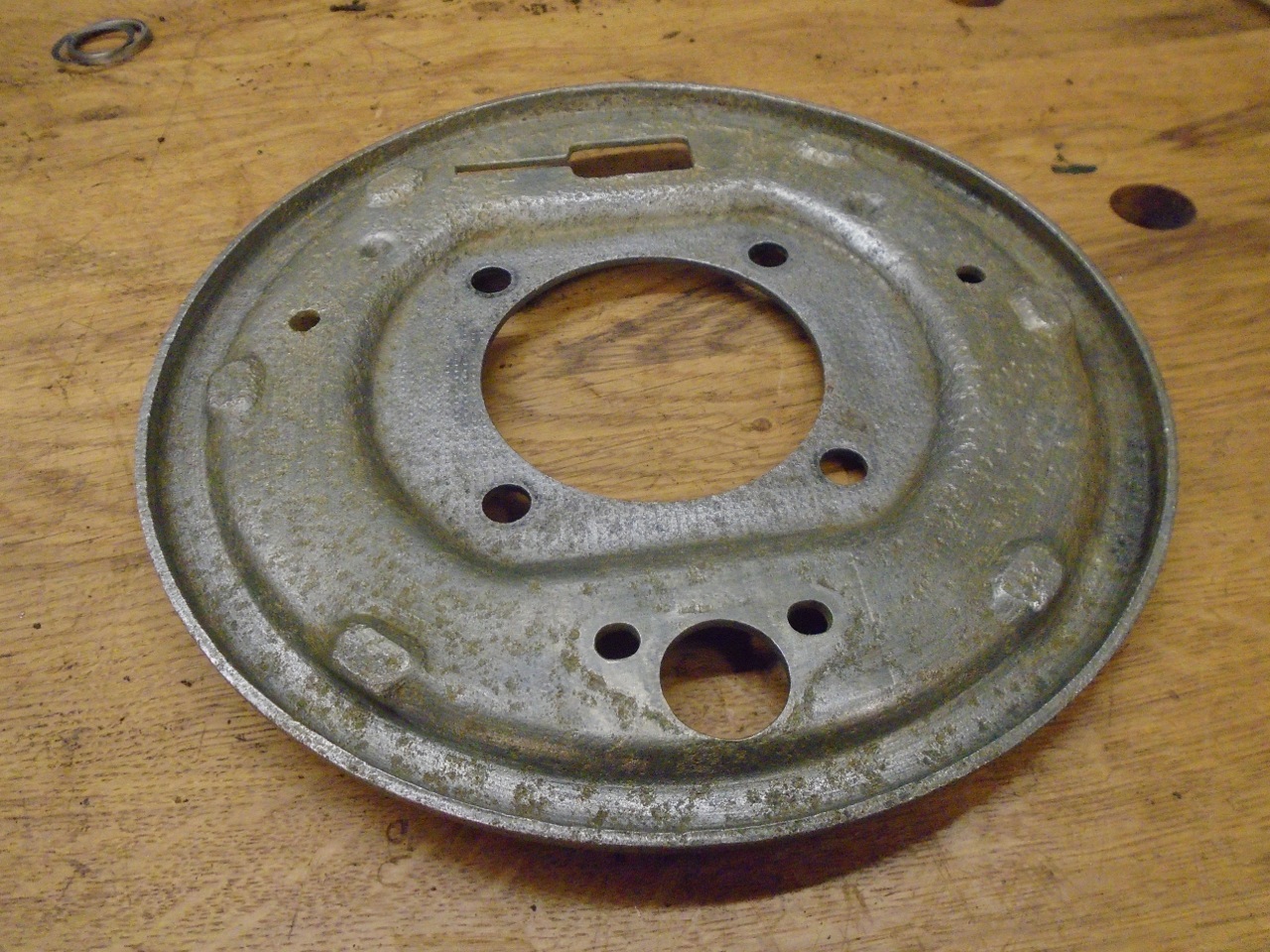
I
realized about this time that the brake backing plate also had to be
included. It was heavily rusted, and derusting revealed quite a
bit of pitting. Nothing that would affect function, but it looked
bad. I think I would have bought new plates if I had found
someone selling them new. Buying used ones seemed to invite
disappointment, so I just put on a heavyish powder coat on them, and
rationalize that no one will see them.
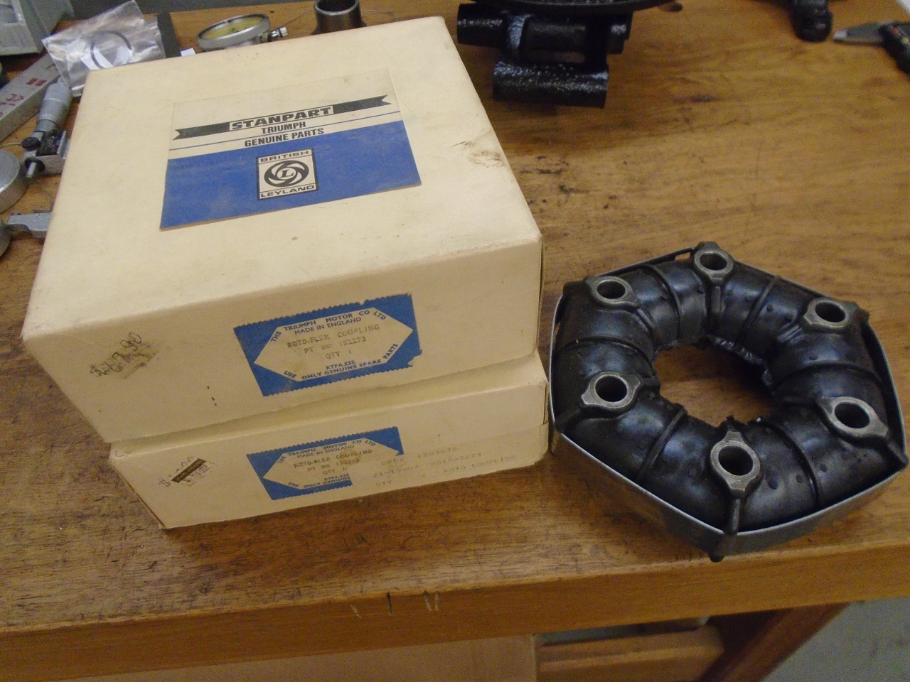
I
bought a pair of Rotoflex couplings back when I was driving the car,
but abandoned the idea of replacing them when I found out how involved
it was. I'm glad I kept them. I'm mildly concerned about
their age, but they have been stored in their original boxes in a cool
dry place all these years.
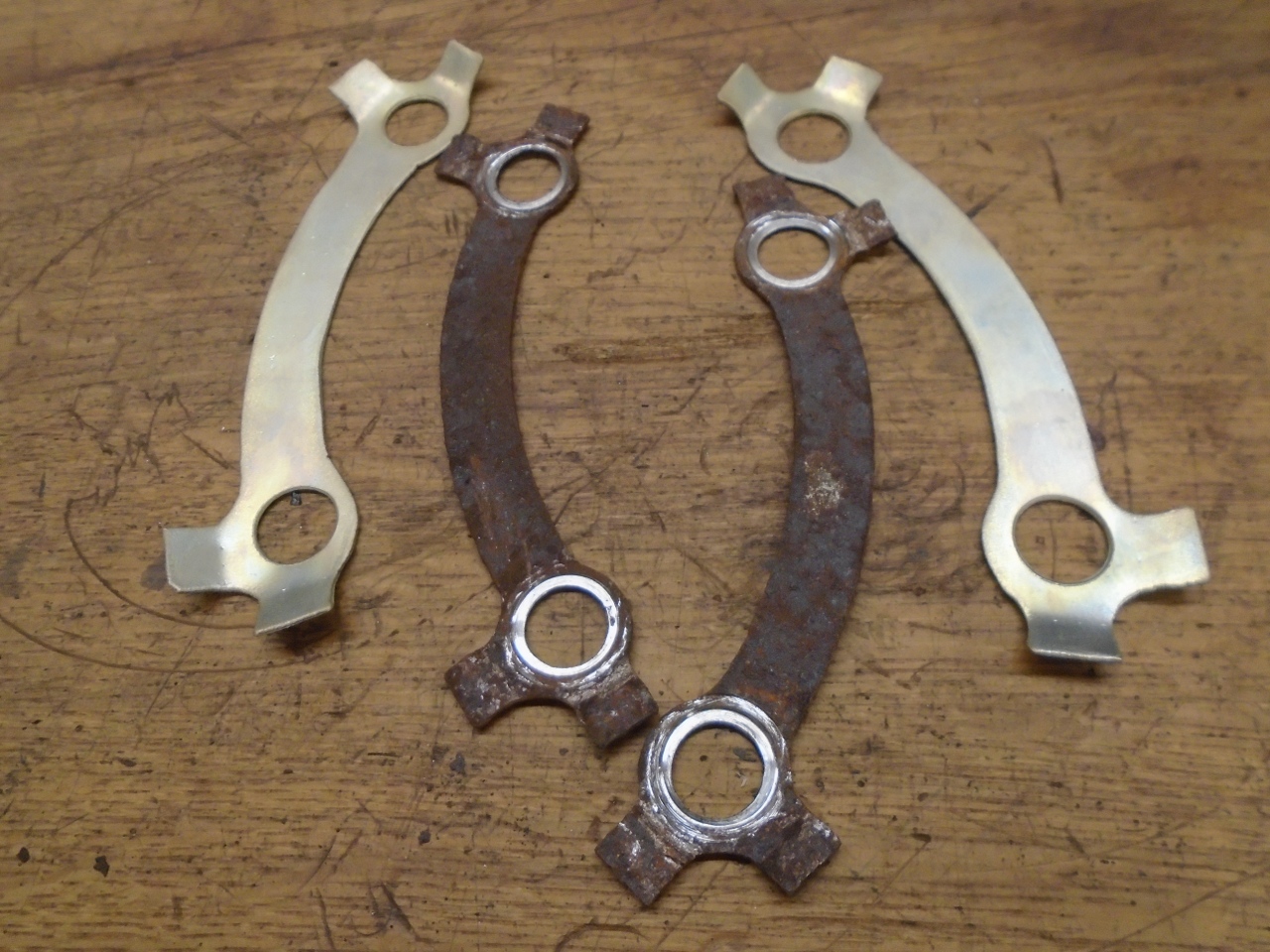
OK,
ready to start assembly. Those tab washers for the brake backing
plate are the kind of thing that I can't seem to remember to order.
Rather than wait another week for them, I made some that are
close enough to work.
The
trickiest part of putting everything together is to end up with the
correct amount of bearing clearance. The factory manual mentions
a special too to help with this, but most of us have to find another
way. My approach was to assemble the bearings with no clearance,
and measure the room they need. Then, provide that much room plus
the 0.0005"-0.0025" clearance.
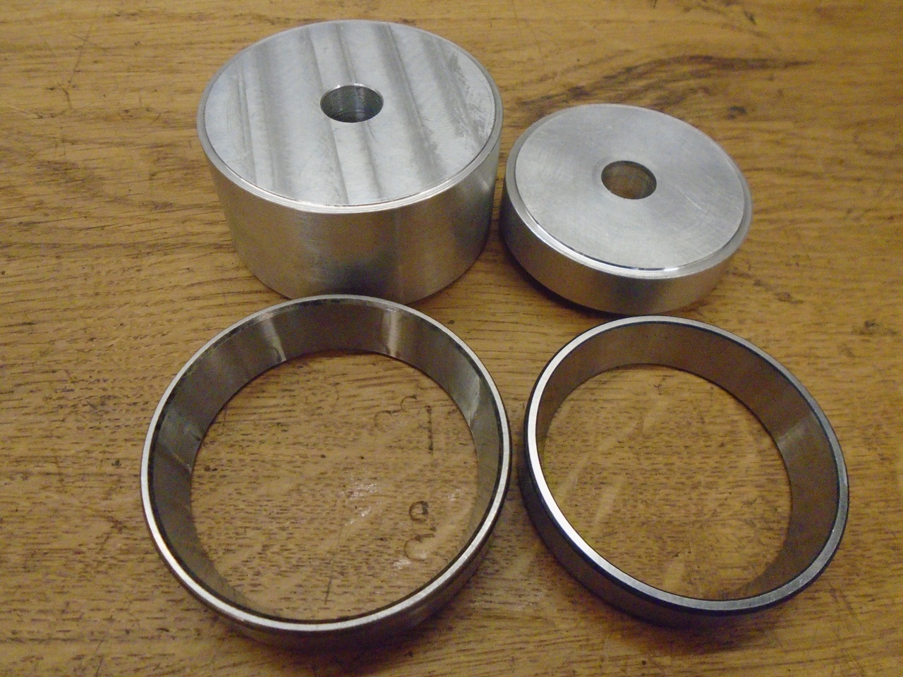
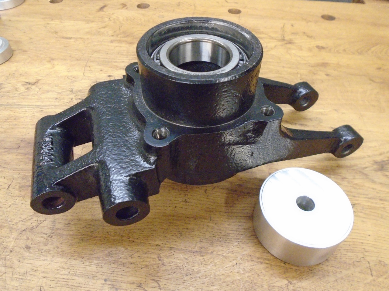
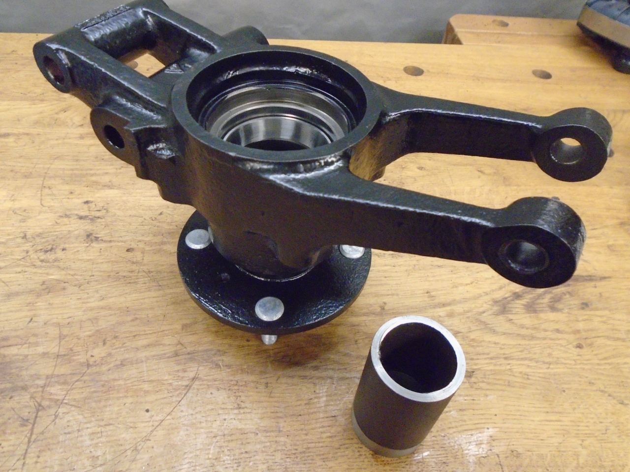
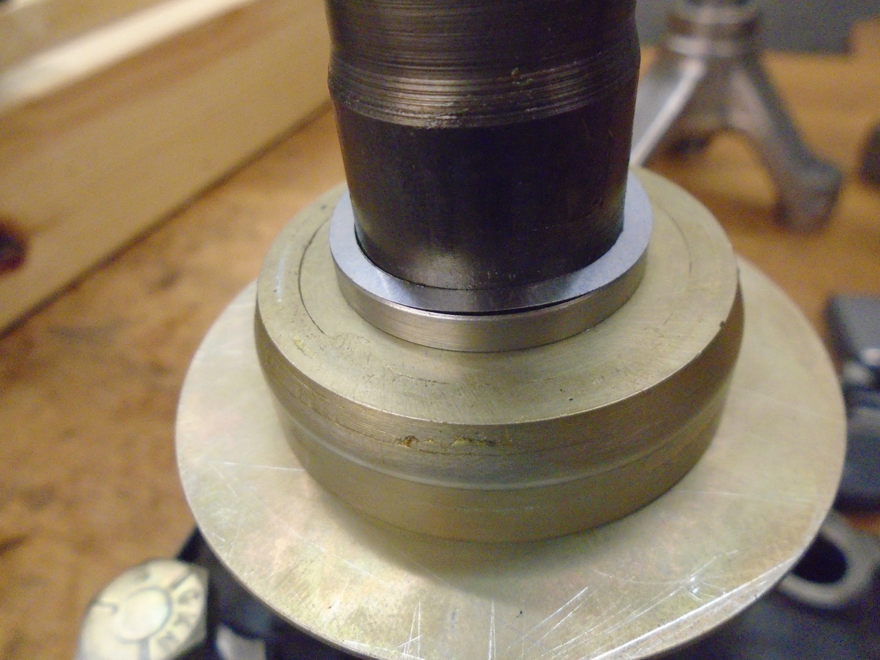
First, the bearing cups had to go in the vertical link. The aluminum disks are sized to help push the cups in straight.
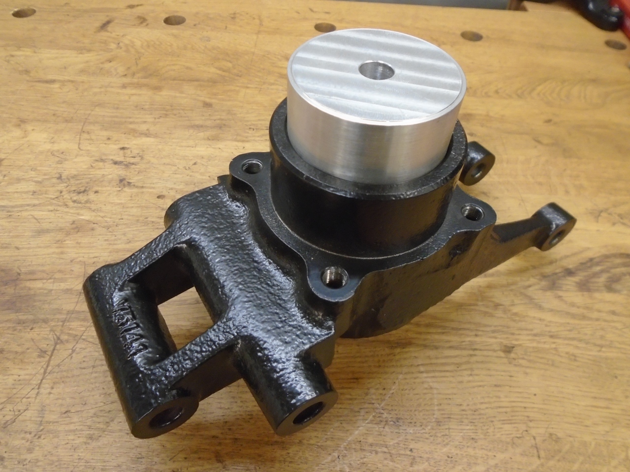
To
find the size of the stacked bearings, I started with a flat topped
slug, and put the inner bearing cone on it. The slug has to be
tall enough to hold the link's arms off the table.
Then
place the vertical link over the slug, so that the inner bearing cone
seats in its cup. Then drop in the outer bearing cone.
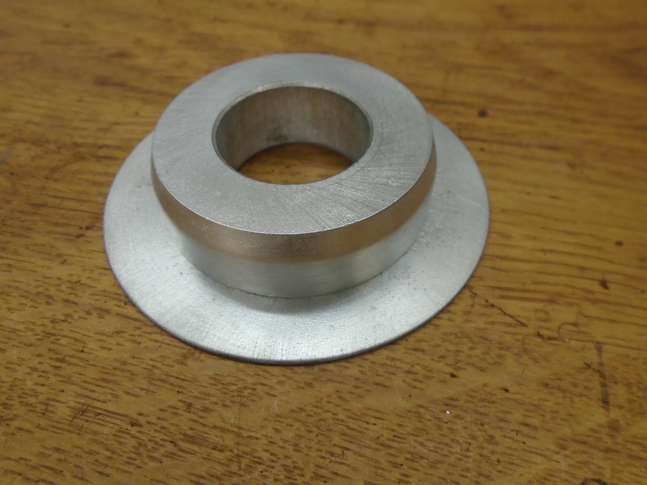
I
then placed this aluminum puck on top ot the outer bearing. The
puck is machined with parallel faces and a precisely known
thickness.
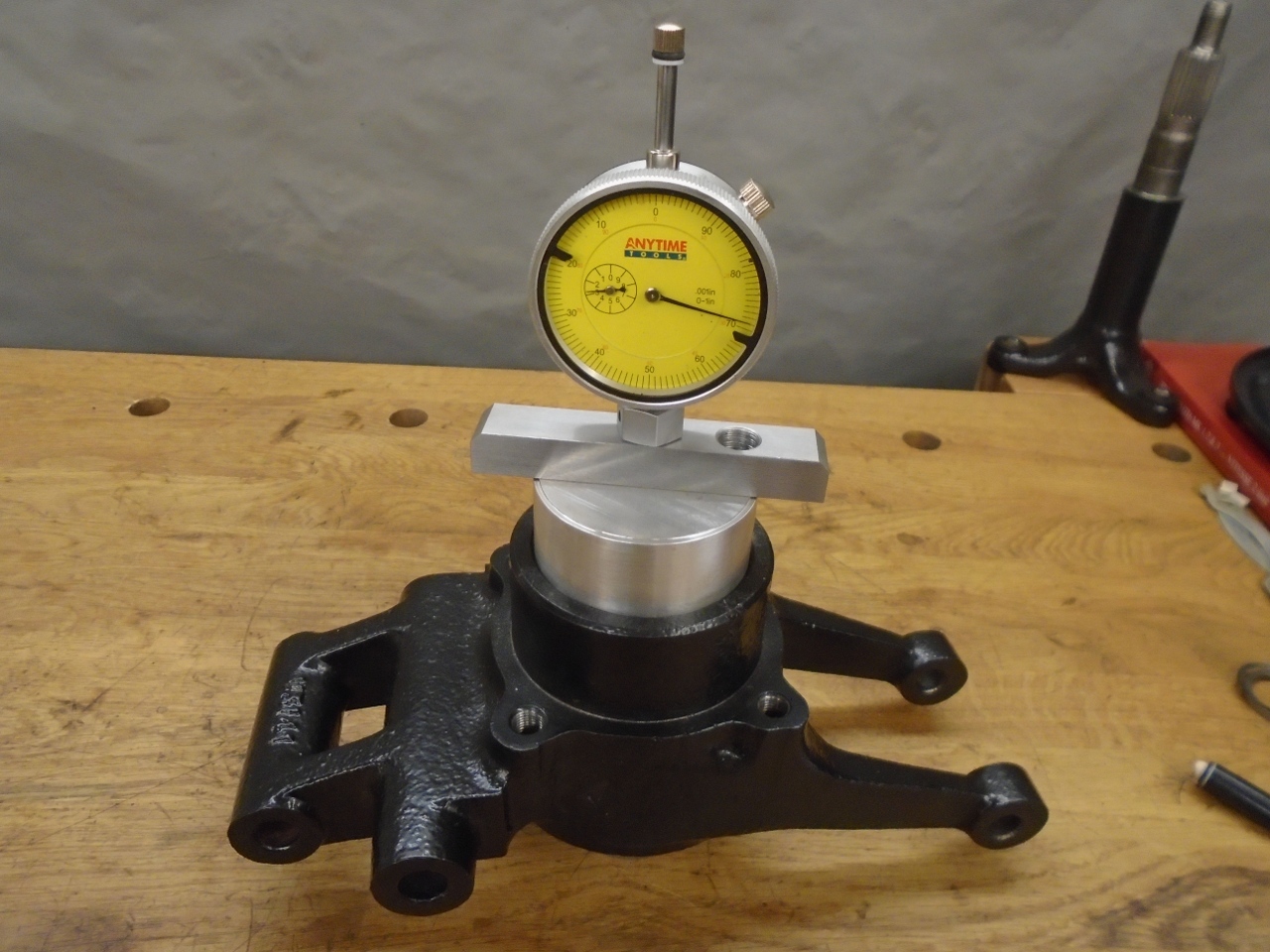
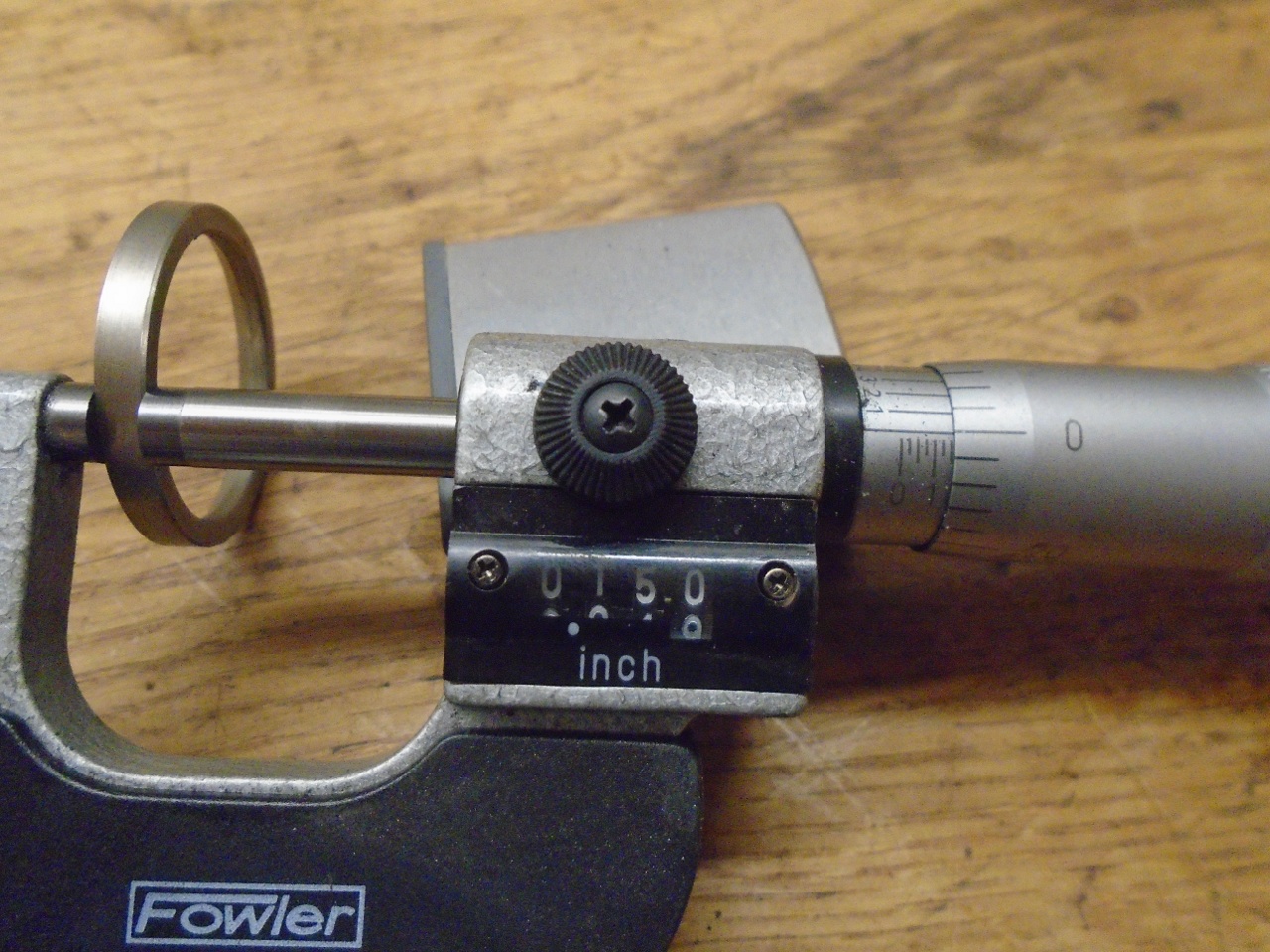
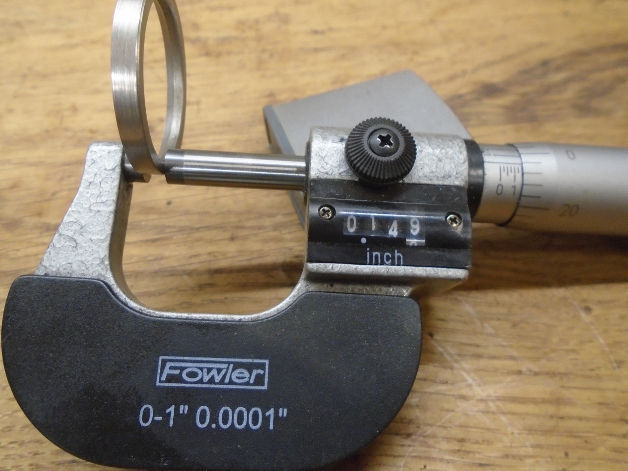
Then,
a measurement was taken with a depth gauge from the top of the puck
down to the top of the slug. This distance, minus the thickness
of the puck, is the minimum space the bearings need.
Now,
the amount of space provided for the bearings is determined by the
length of the hub nose, plus spacers and/or shims. I measured the
length of the hub nose from its tip to the bearing seat surface, and
then figured how much additional room I had to provide for the bearings
to fit, plus clearance. This additional room is provided by
spacers and shims.
Here is where I discovered a little factory
quirk. The clearance spec is 0.0005" to 0.0025"--a window of
0.002". However, the smallest factory shim is 0.003". This
means that, mathematically anyway, it could be impossible to hit the
factory spec with factory parts.
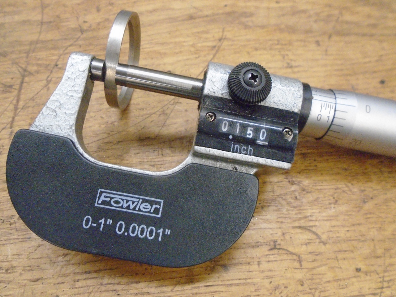
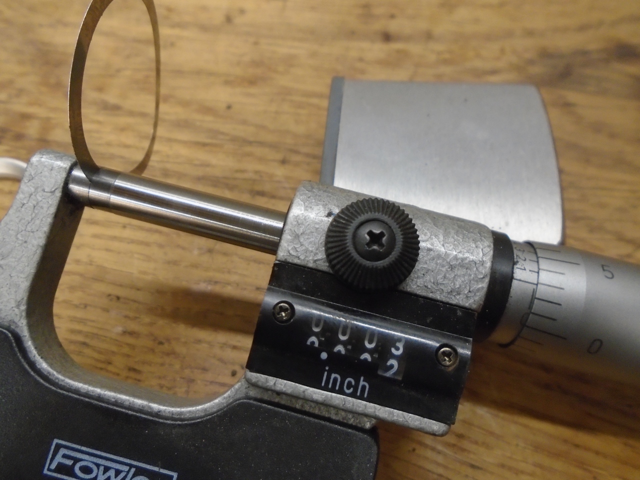
Where there is a will, there is
a way, though. On both of my hubs, I was able to fine tune the
clearance by lapping the original spacer. It was easy to
remove a thousandth or two by rubbing the spacer on fine sandpaper on a
flat surface. My original spacer on one side was 0.155", but I
needed it to be 0.150".
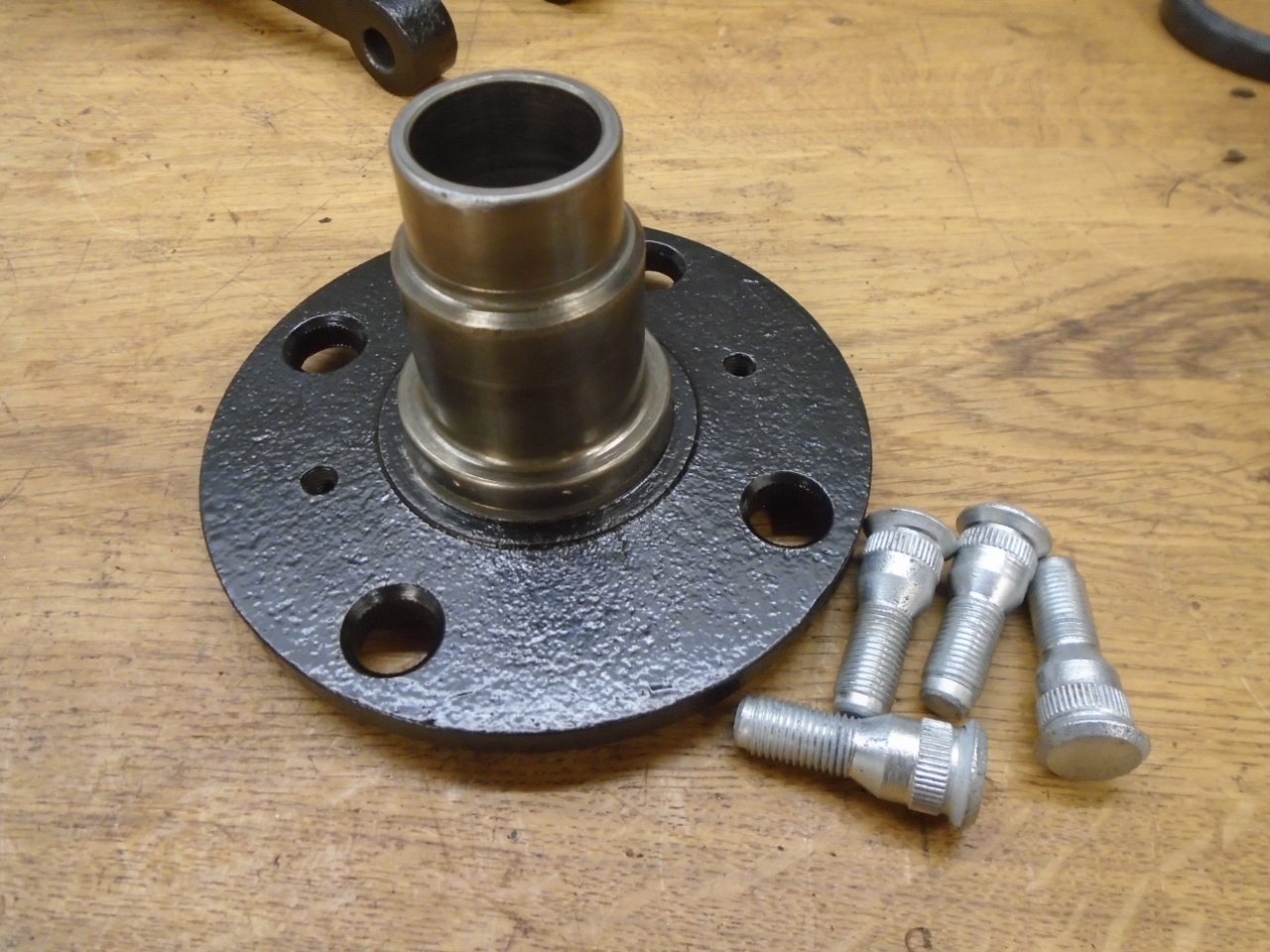
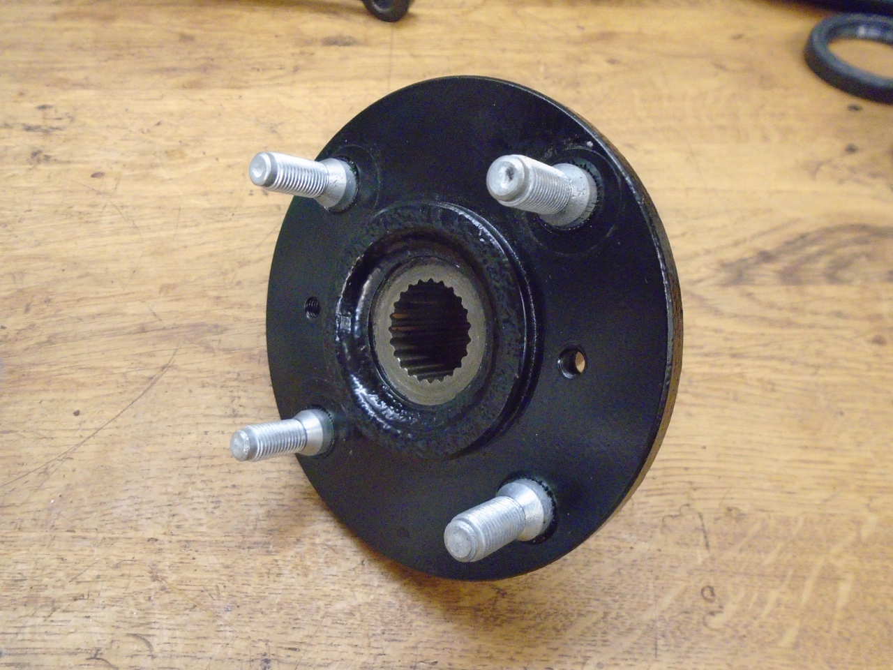
Once
I was confident of the measurements and calculations, assembly could
begin. First, the hub was prepared by pressing the replated
original wheel studs in place.
At
this point, the factory manual says to install the outer bearing cone
and grease seal, and join the hub to the vertical link, so that's what
i did.
I
should have thought about it a little more, though. The manual
doesn't say it, but the brake backing plate has to go on first.
That backtrack was good for an hour or so. The outer
bearing is pressed onto the hub nose.
Then the inner bearing and
seal. The bearing is not pressed all the way on. It is
pushed into place after the axle is installed.
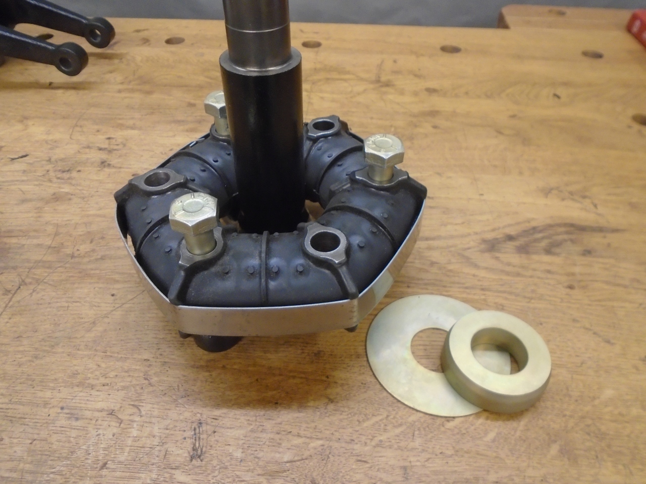
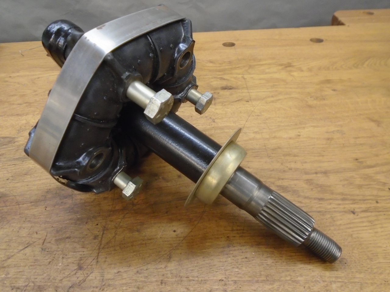
The
Rotoflex joint has to go over the axle before the spacer and stone
guard disc go on. The spacer and disc cleaned up and plated
really well. It's a good thing--I don't think they are available
new anywhere.
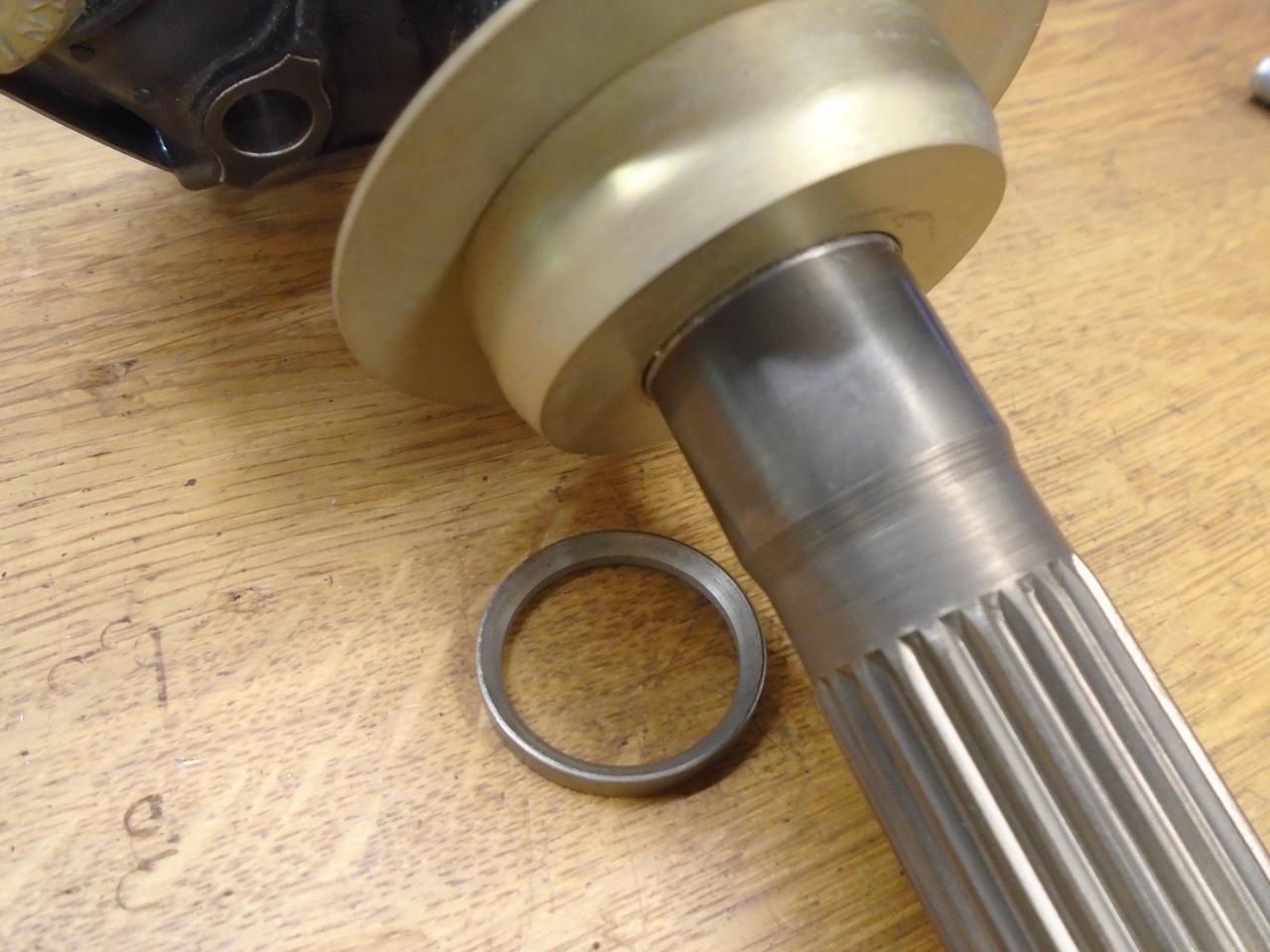
Another
small issue with the manual. For the spacer that helps set the
bearing clearance, it says to use the latest type, without the chamfer.
Well that chamfer is clearly there for a good reason. The
journal for the large spacer is a little longer than it needs to be, so
a chamferless spacer could hang up on it and mess up the bearing
clearance.
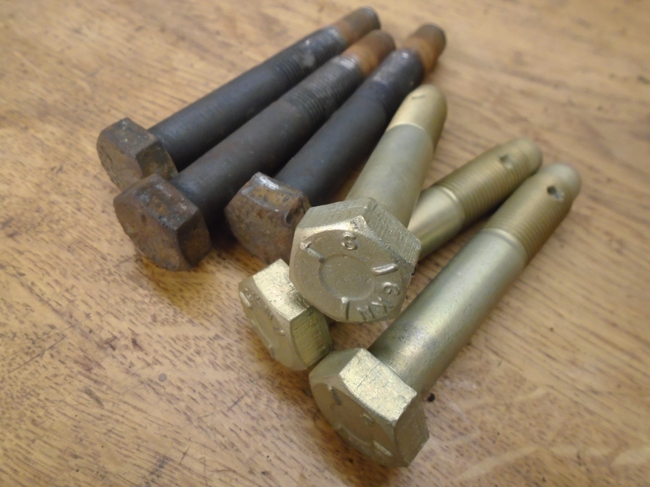
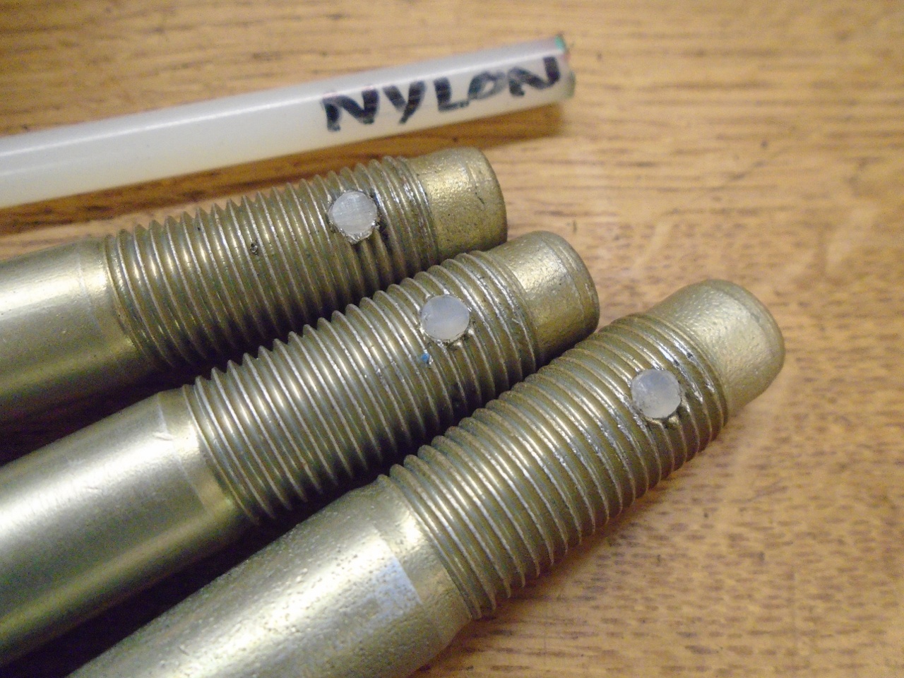
Likewise,
the bullet-nosed Rotoflex bolts responded well to replating. They
are actually lock bolts. They have a little nylon button in the
threaded area to lock them. A dab of Locktite probably would have
done the same thing, but I found a little piece of nylon.
So
then the hub/vertical link assembly was lowered onto the axle shaft.
The manual says to use the axle nut to draw the shaft into place,
but in my opinion, a press works better.
The
second assembly went way faster than the first one. Actual
clearance is a little hard to measure on these units on the bench.
Target clearance is small, and there is pretty heavy grease
inside, so trying to move the hub relative to the backing plate gives
uncertain results. There is no detectable play, but the hubs
rotate smoothly and freely with about the same drag as they had
from the seals only before tightening the axle nut. I'll try to
measure clearance when they are mounted on the car, but for now, I'm
calling them good.
This was some new territiory for me. Once I grasped how it went together, it got easier.
Cost was only around $60 for the bearings and seals since I had the Rotoflexes on hand.
UPDATE: September 29, 2019
I
mentioned above that it was pretty hard to get a good measurement of
bearing float with the assemblies on the bench. I was finally
able to get the hubs mounted on the frame, where it was a lot easier to get good measurements.
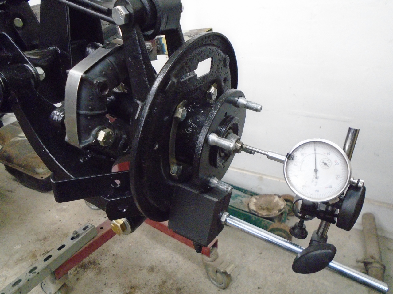
Happily,
the right side hub came in at 0.0005-0.001", just inside the spec
window. However, on the left side, I couldn't get the needle to
budge at all. I had essentially zero float.
So, that side had to come apart.
This was the side where I had to reduce the thickness of the axle spacer. Well, I apparently reduced it a little too much.
Since the hub turned about as freely as the other side, I
assumed that there wasn't a lot of preload, so I could call the float
zero. I decided to add 0.002" to the spacer/shim pack.
Unfortunately, all I had was 0.003 shims, so I first had to lap
another 0.001" from the spacer.
And then add the 0.003 shim.
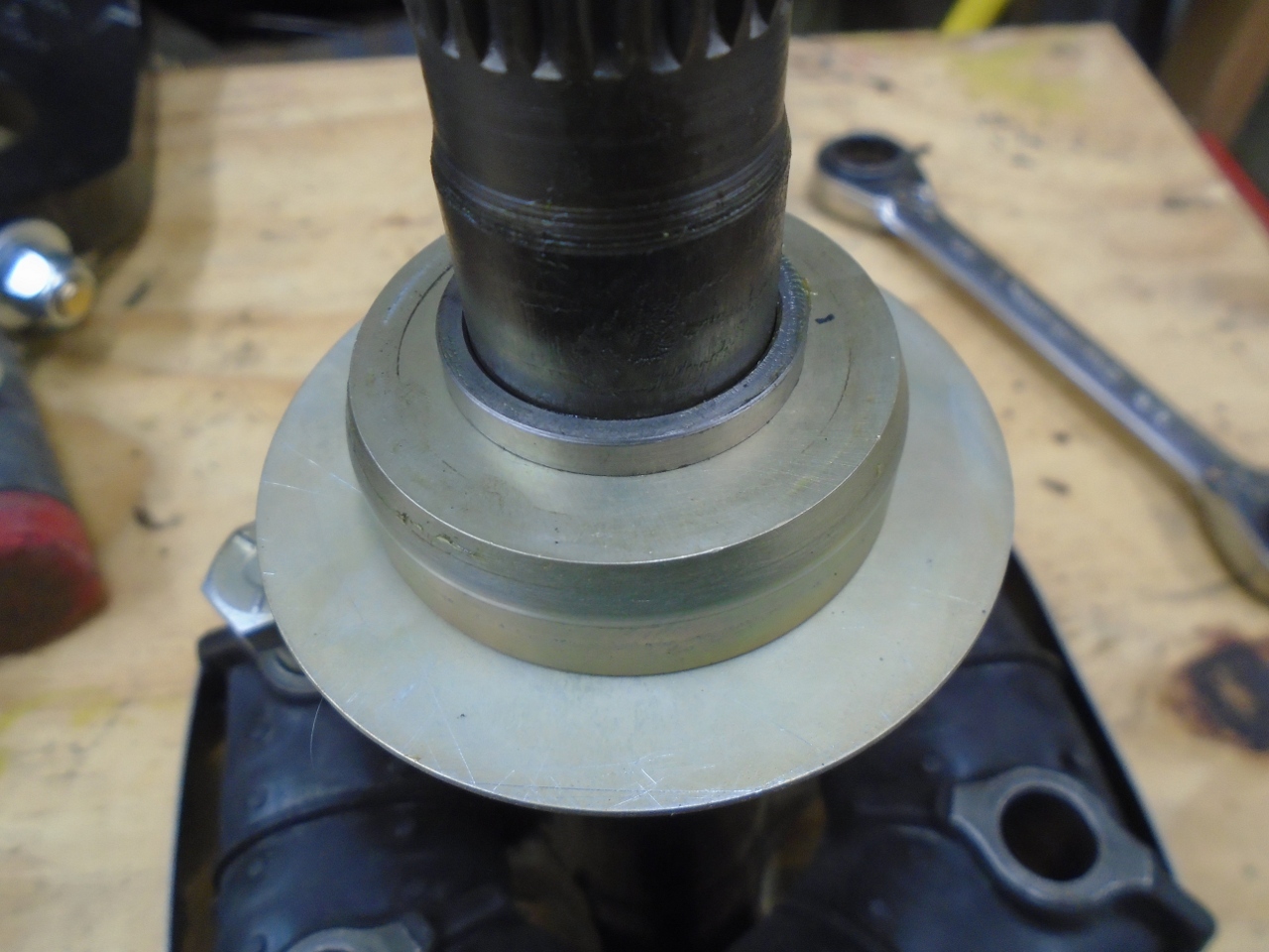
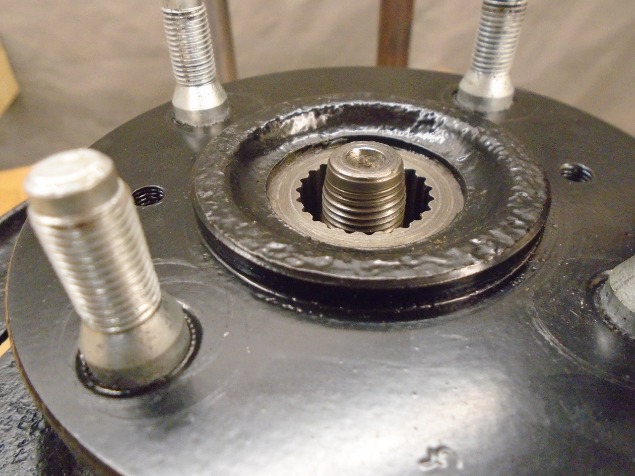
Before
putting it back together, though, it was necessary to shift the inner
bearing slightly. Pulling the axle shaft doesn't move that
bearing, so it would still be too tight. That innermost cylinder
is the nose of the hub, and I just tapped it back slightly with a
drift. The axle will drive the bearing to the correct position
whan it is tightened.
The assembly is lowered onto the axle and pressed into place.
I'm happy to report that after re-mounting and remeasuring, the float is now 0.001".
What
caused this problem was that when I did my calculations for the needed
spacers/shims, I used 0.001" as the target end float value.
However, the measurements of the hub nose distance were taken
under no-load conditions. I think that placing that nose under
compression from the 100 ft-lb axle nut essentially used up all of the
float allowance.
The lesson here is that when doing the shim calculation, use a somewhat larger value (0.002", maybe) as the target.
All's well that ends well, I guess.
Comments to Ed at elhollin1@yahoo.com
To my other GT6 pages