To other pages
September 18, 2013
Odds & Ends
[Click the pics for a larger view]
Getting
really close to fished on this project. Just dealing with a few
final issues. I'll outline them here, in no particular order.
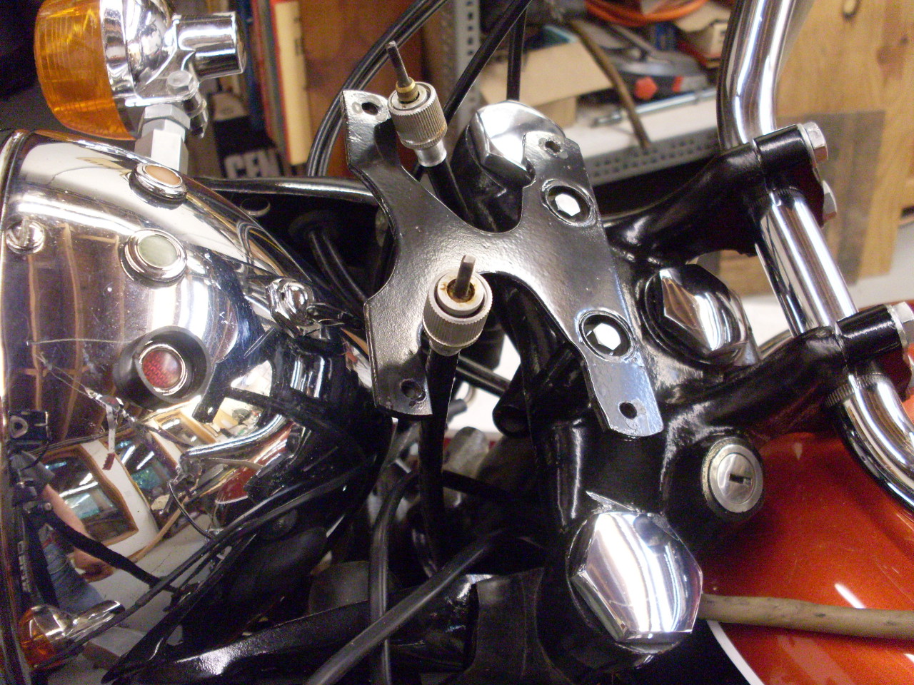
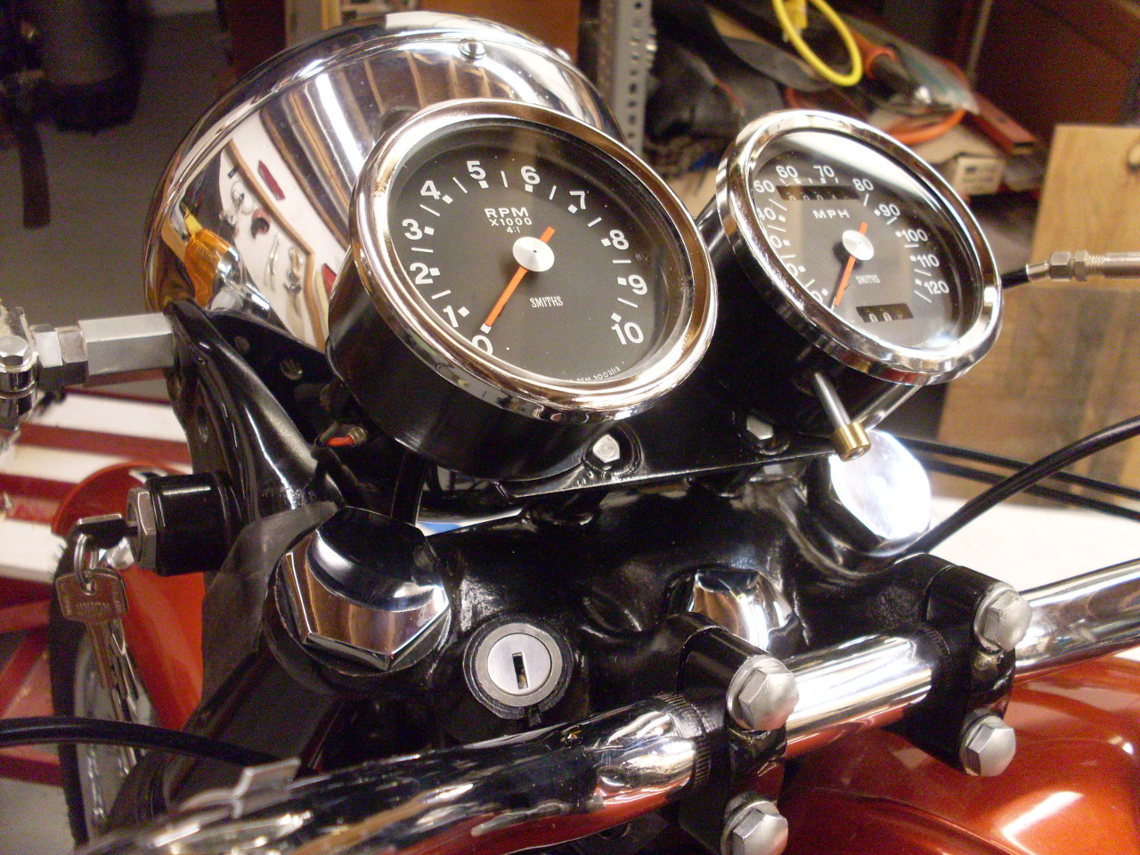
Mounting the Instruments
I
routed the tach and speedometer cables, gathered up the instrument
light sockets hanging form the harness, and secured the instrument
mounting bracket with new metalastik bushings and replated special
screws. Then offered the newly rebuilt insrtruments. This really adds a lot to the look of the bike.

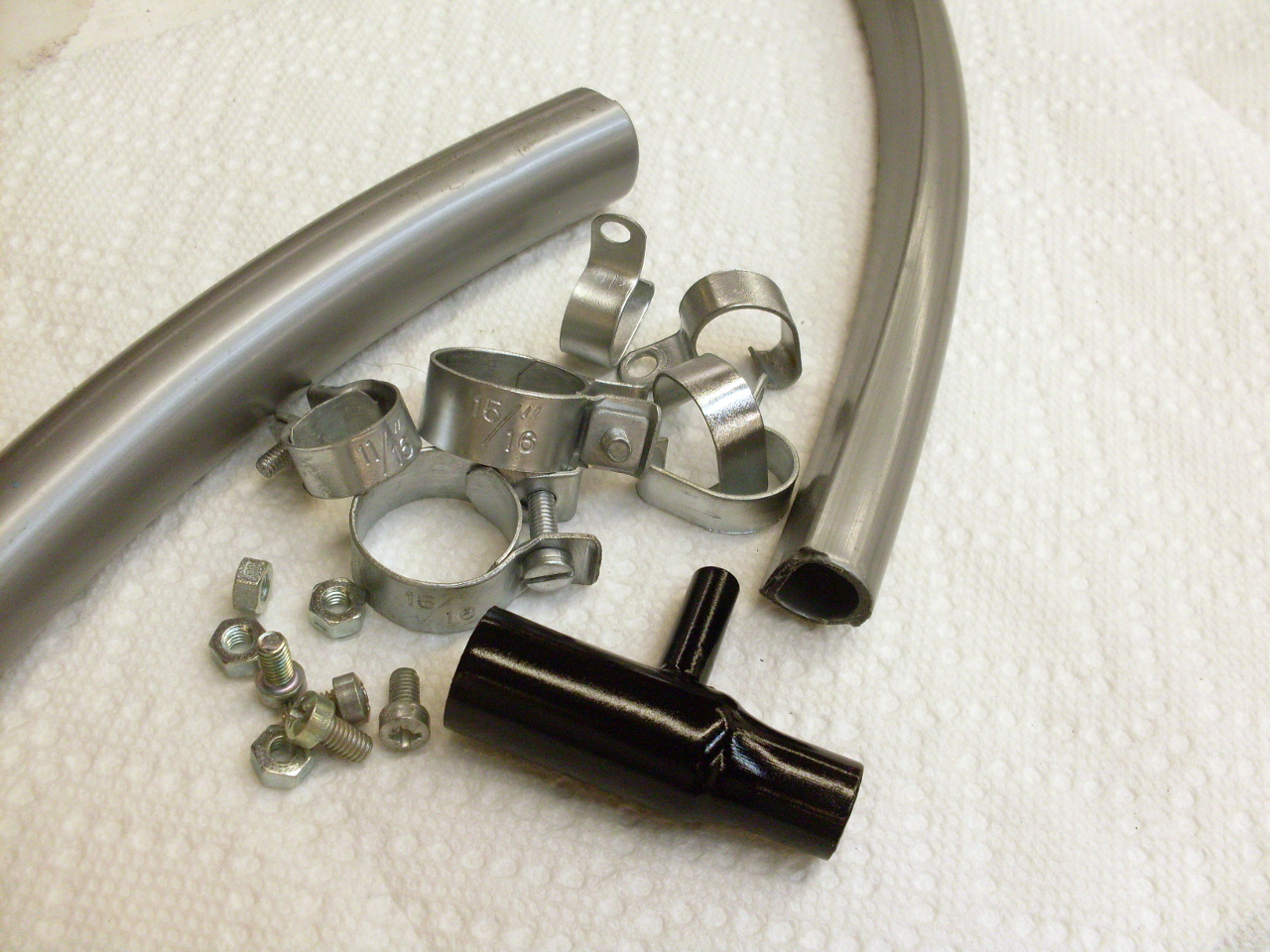
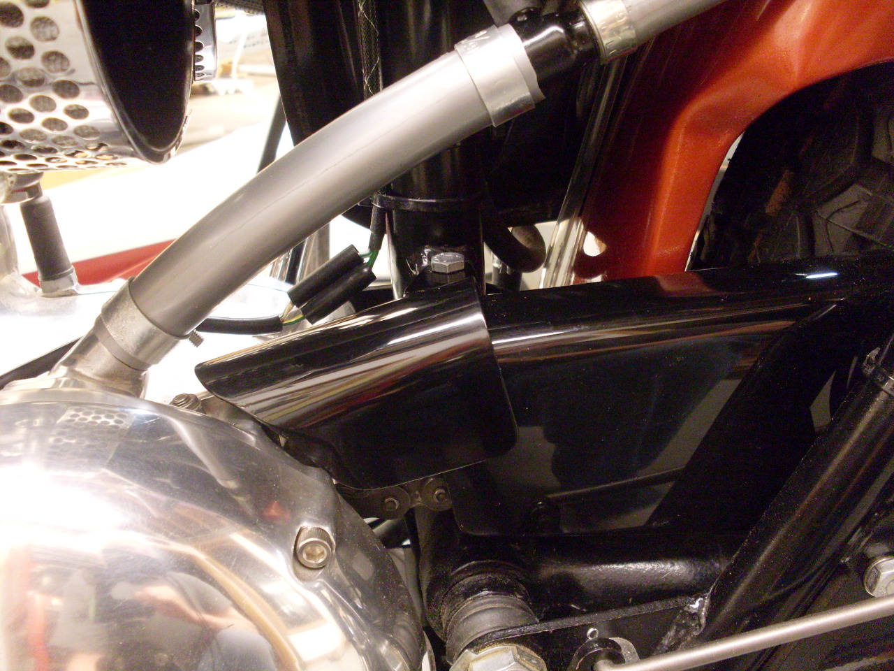
Crankcase Breather Vent
The old breather vent system's hoses were stained and hardened from age, and the clamps and other harware were rusty.
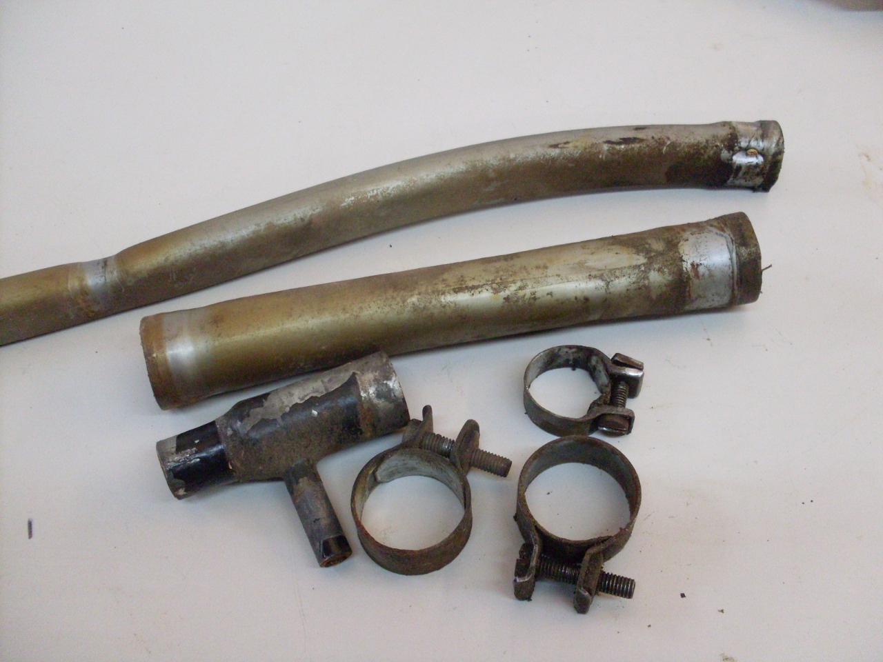
I
got new hoses, replated the hardware, and cleaned up and painted the
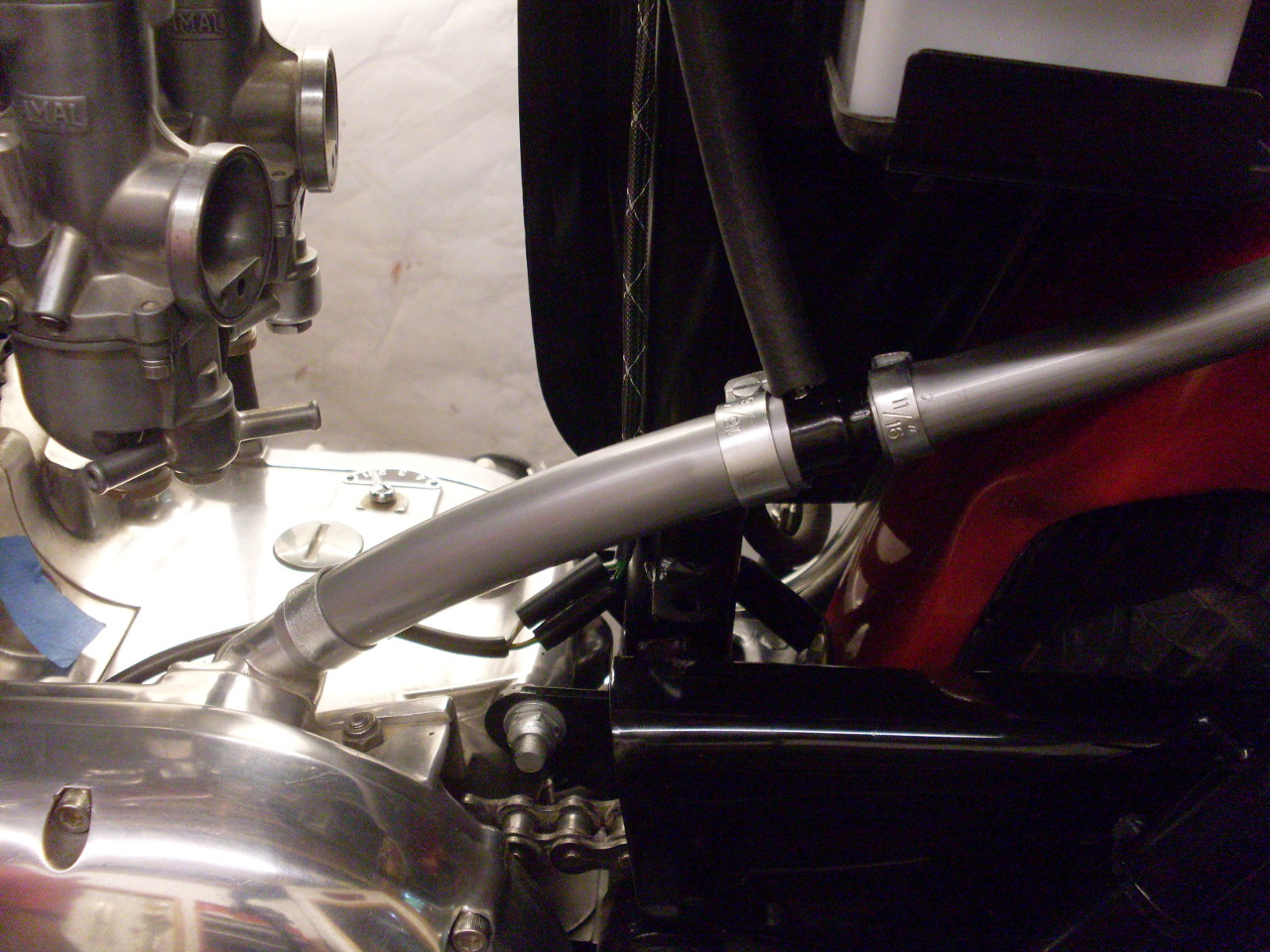
"T" piece that accepts the small hose for the oil tank vent.
Here's the new vent system installed:
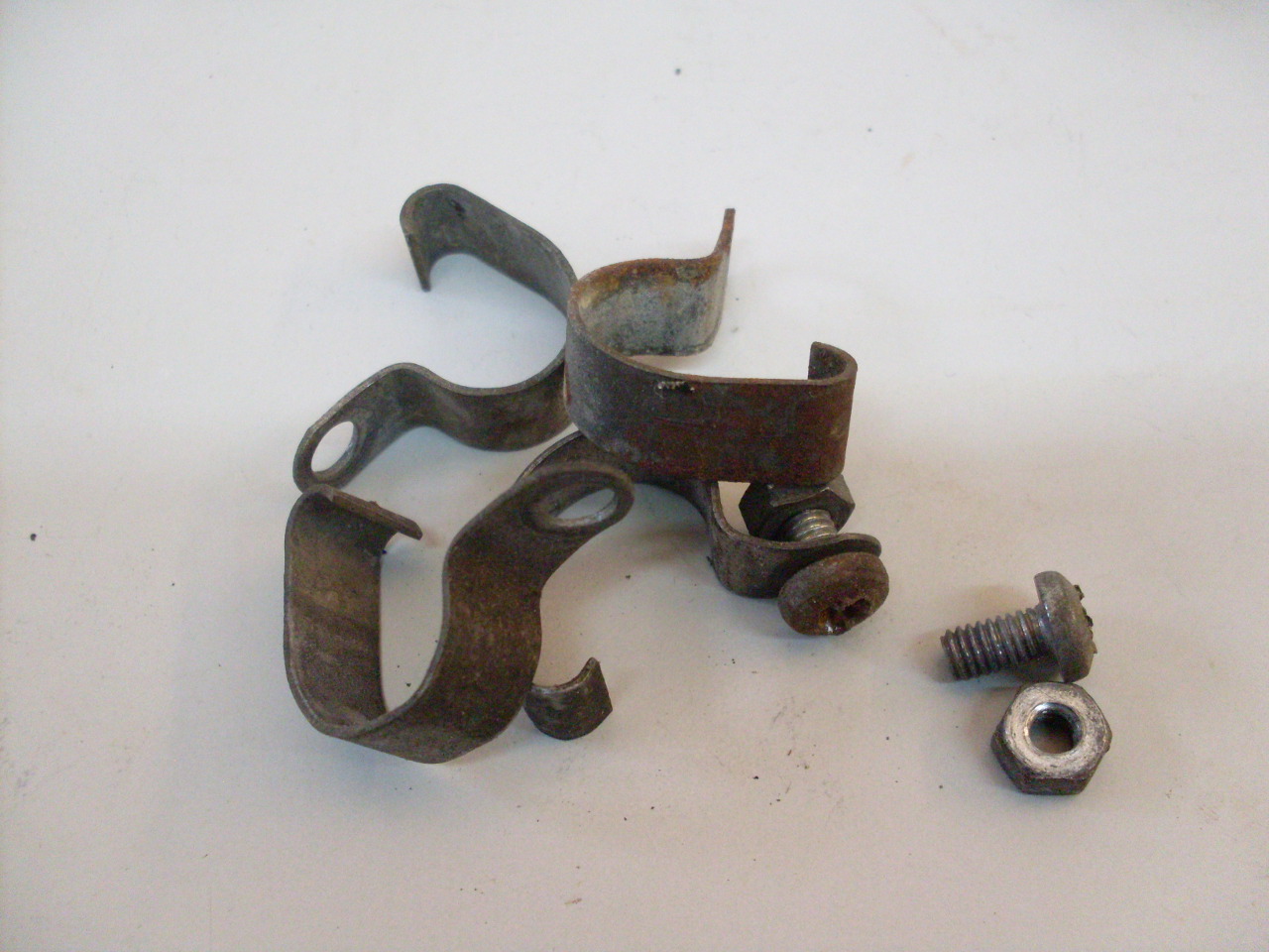
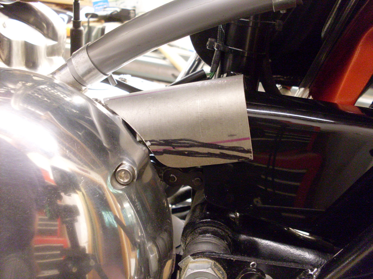
Front Chain Guard
For
some reason, probably known only to Triumph designers, the chain guard
on this bike doesn't extend all the way to the drive sprocket housing.
There is a one or two inch gap where the chain is exposed.
Triumph covered this with a kludgy little "front chainguard" that
bolts to a small bracket welded to the frame upright. Well, mine
had gone missing, and the prices for original or reproduction items
were just silly. Having the guards missing must be common,
because I couldn't find a used one in my admittedly limited search.
I was able to accumulate a number of pictures of the piece,
though, and it looked like I could just make one.
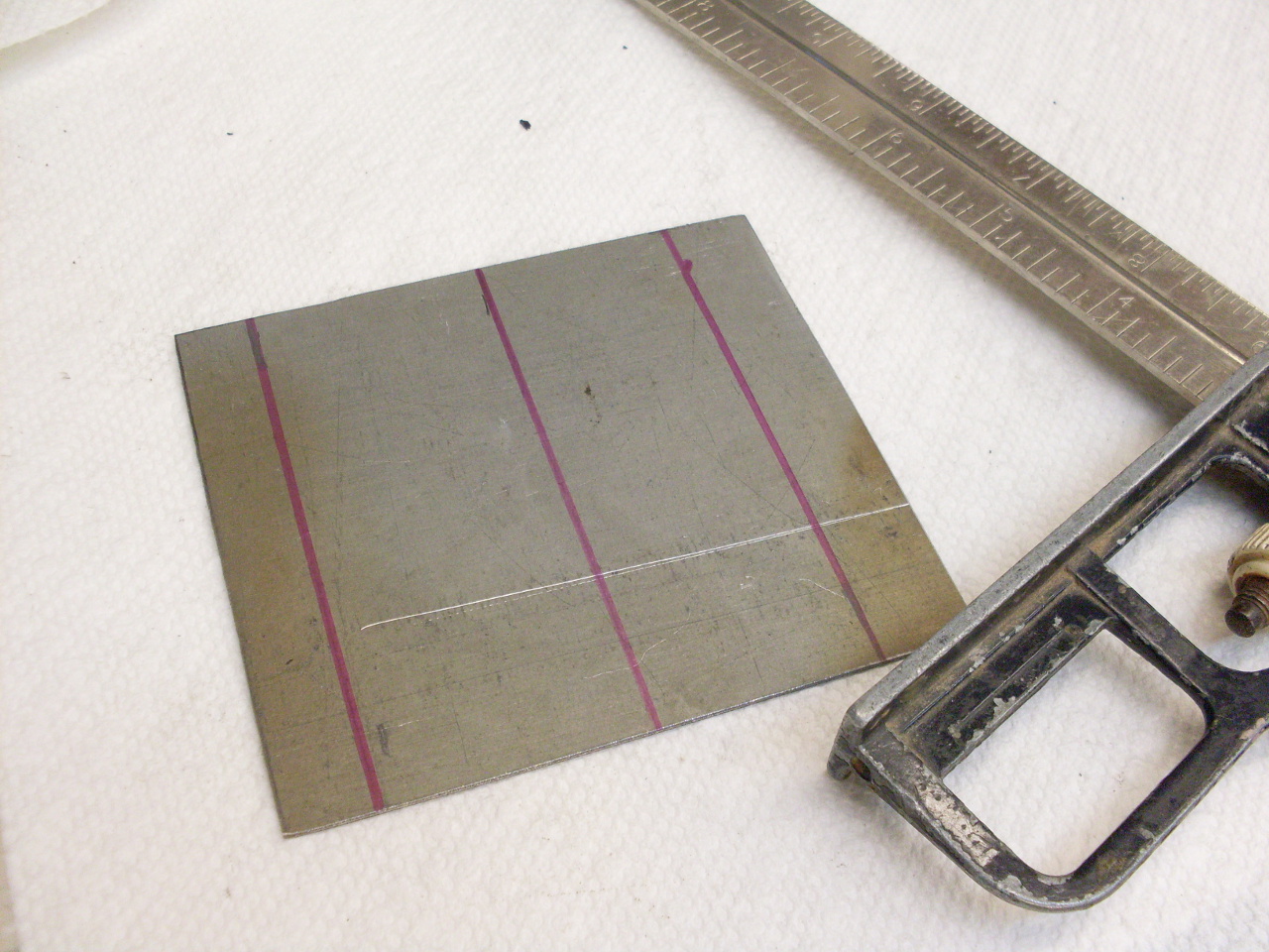
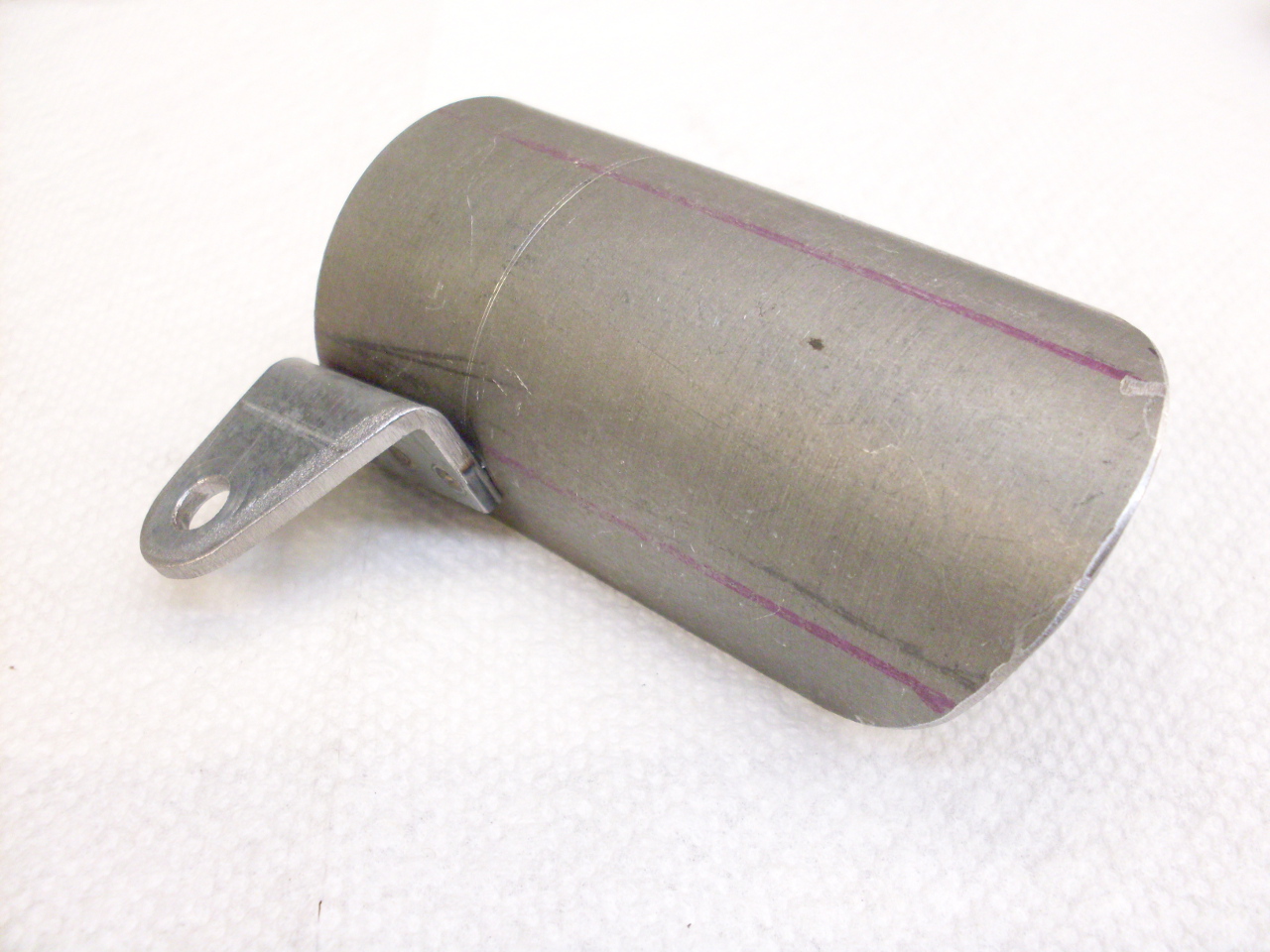
Started with a
scrap piece of 22 gauge galvanized sheet metal, and cut it to a rough
overall size I derived from looking at the pictures and measuring the
space on the bike.
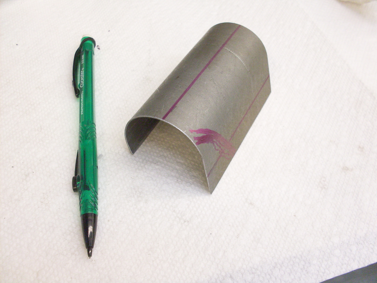
I
curved it around a piece of 1-1/2" pipe, and then rough cut the
contour to fit the area around the drive sprocket housing.
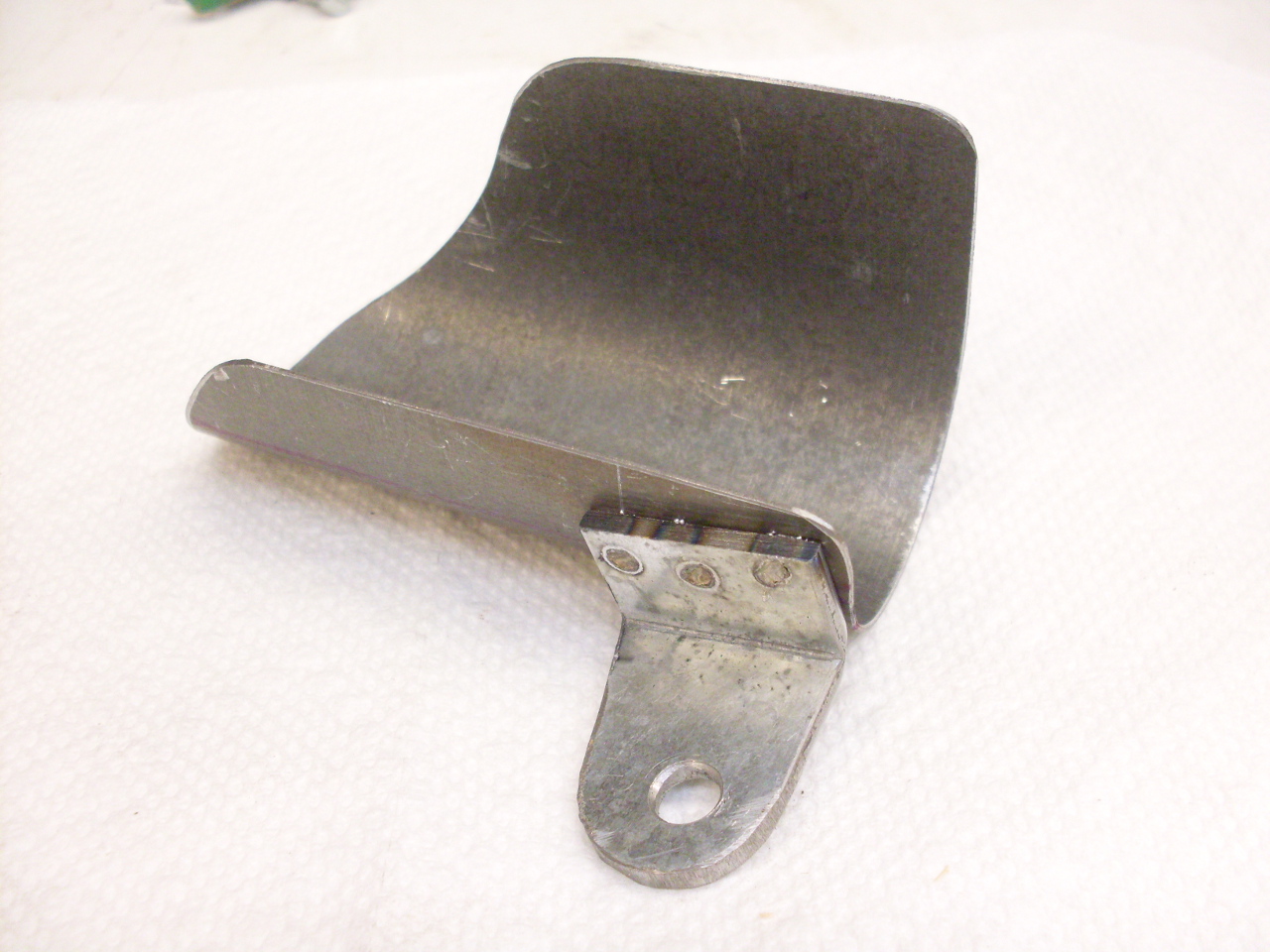
Cut a small bracket out of piece of 1/'8" galvanized, bent it to a right angle, drilled it, and shaped it to a pleasing contour.

I
have an old spot welder I picked up salvage, so I used it to attach the
bracket at the correct odd angle. Without the spot welder, I
would have maybe pop riveted it, or maybe even tack welded it.
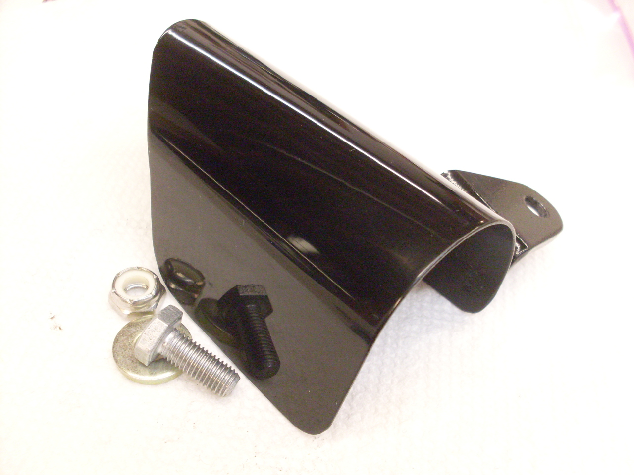
Some
primer and a few coats of black and clear lacquer, and I have a part as
good as anything I could buy. Total fab time: an hour or so
(not counting paint drying time). Total material cost:
pretty close to $0.
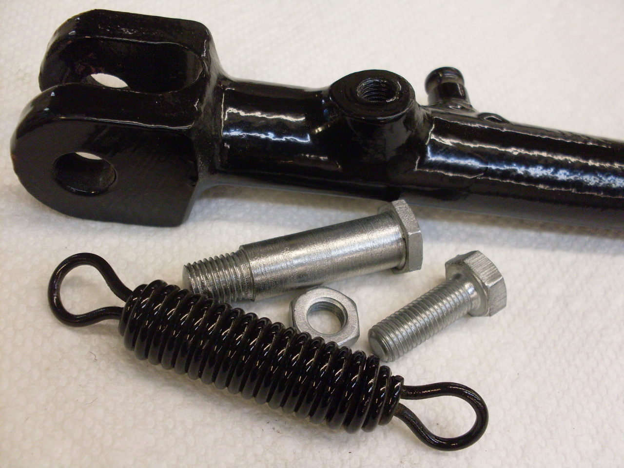
Shift & Kickstart levers and Kickstand
The
chrome shift and kickstart levers weren't in really bad shape, but just
below the level I wanted to see, so I had them rechromed, and I zinc
plated the rest of the hardware, and got new rubber fittings.
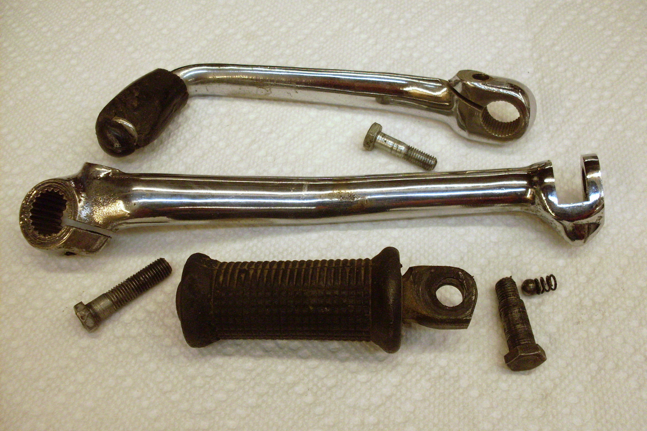

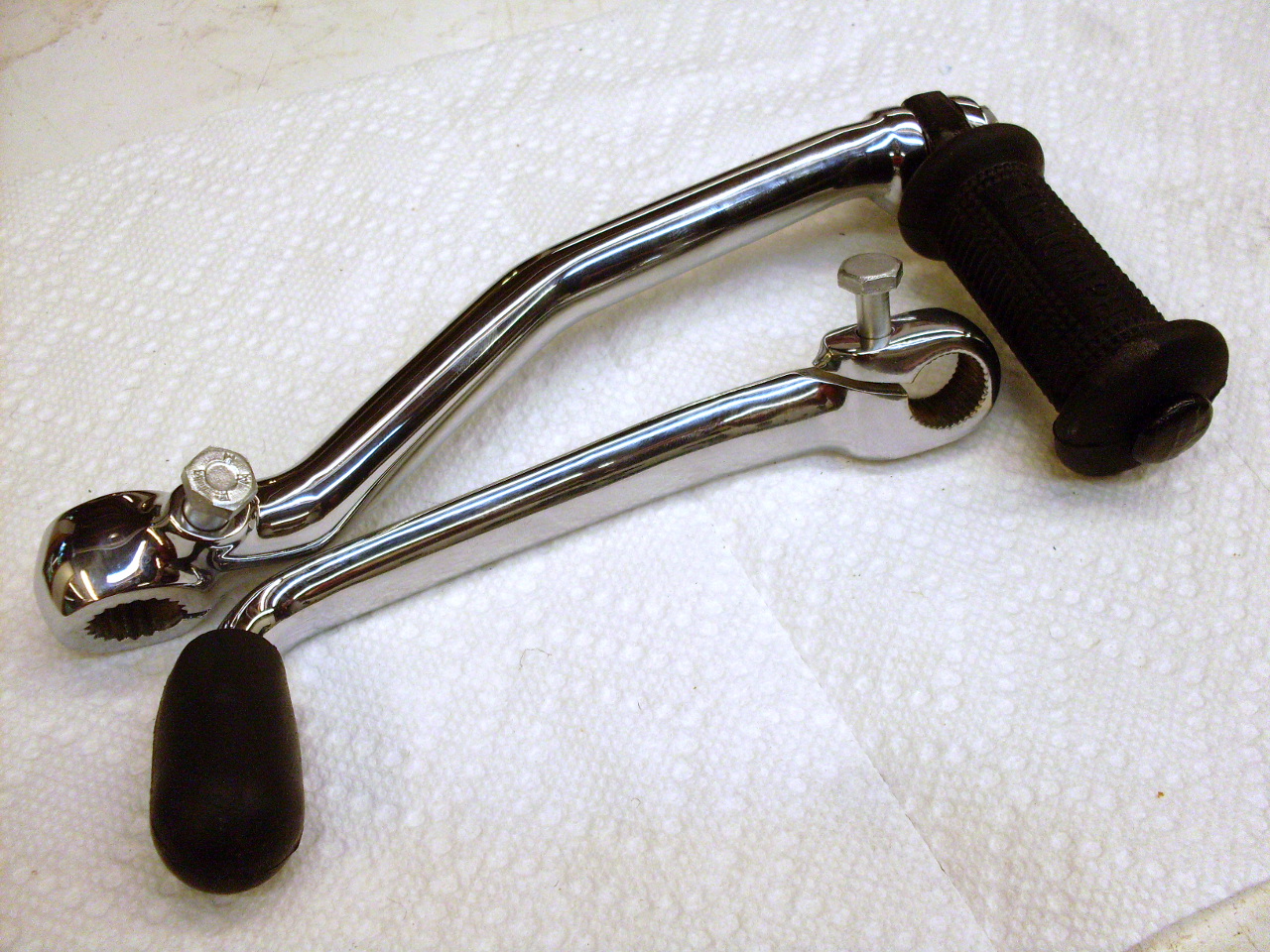
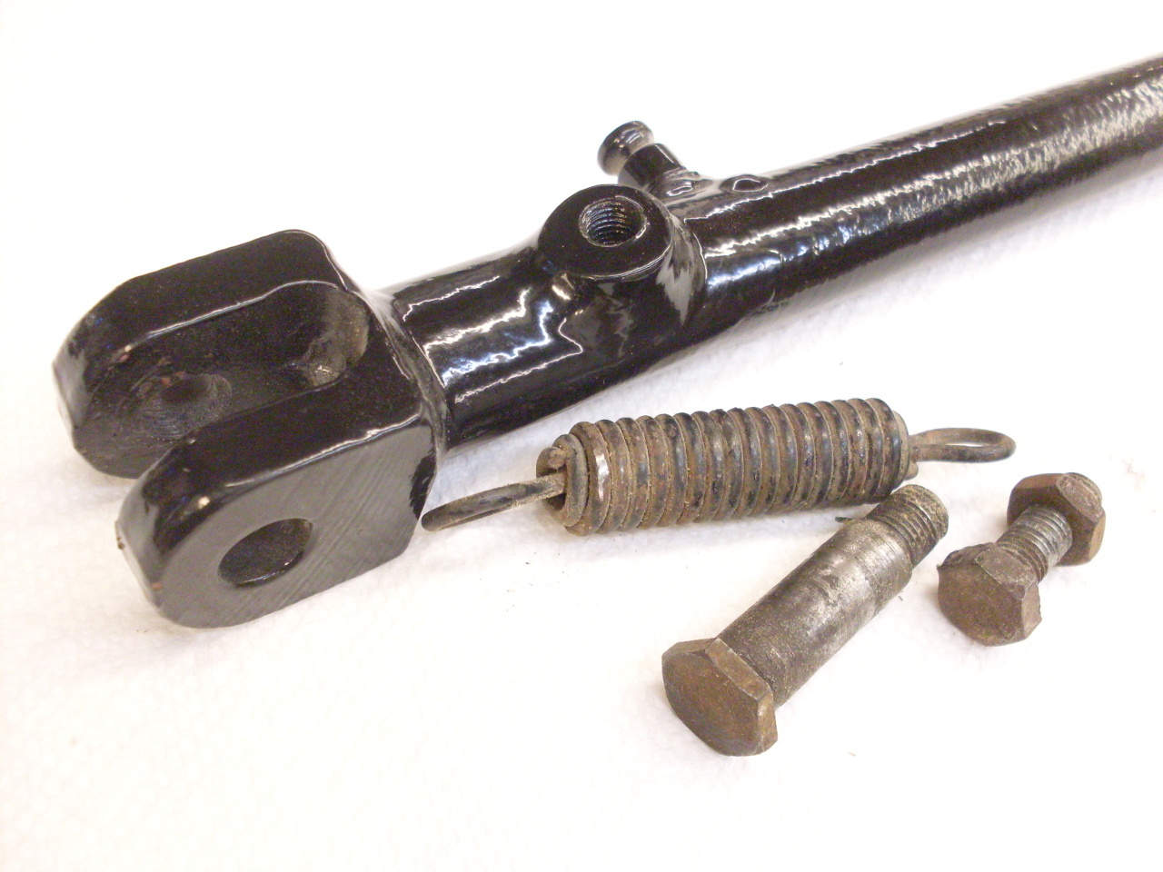
Kickstand parts got the usual treatment--repainting and replating:
Static Timing
In
order to do final ignition timing with a timing light, the engine has
to be running. To get it running, timing has to be close enough
for the engine to start. That is the reason for static timing.
This engine is speced to run with a maximum spark advance of 38
degrees before top dead center (38º BTDC).
This means that with the centrifugal advance unit fully advanced,
the points should open when the crank is at 38º BTDC. To
determine when the crank is in exactly this position, there is a
factory tool that screws into a threaded hole in the top of the
crankcase behind the cylinders. The tool has a sliding probe that
slips down into a recess in the crankshaft flywheel at exactly 38º
BTDC. (There is also a recess at exactly TDC, but you can tell
which is which by observing the position of the pistons or the
alternator rotor.)
I made the factory tool from a common 1/2-13
bolt and a piece of 1/4" rod, but it turns out that on this engine,
it's not really necesary. There is a mark cast into the
alternator rotor and a pointer installed on the primary chaincase that
align at 38º BTDC.


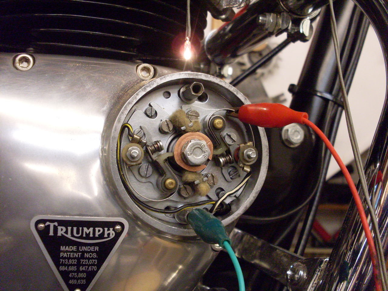
So
with the crank at 38º BTDC, and the advance unit fully advanced, one of
the sets of points should just be opening. This can be checked by
using an ohmeter across the points, but I find it easier to use a
little light wired to a battery, connected so that the light comes on
when the points are closed. On this 6CA breaker assembly, each
set of points can be adjusted independently, so the appropriate set is
adjusted and tightened down. Then after one full rotation of the
crank, the other set of points can be set.
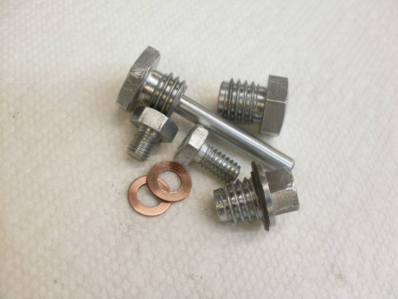
Assorted Caps, Covers, and Plugs
General cleanup, deburring from sloppy use of tools, replating, and new or newly annealed washers:
Think this sump cap can be saved?
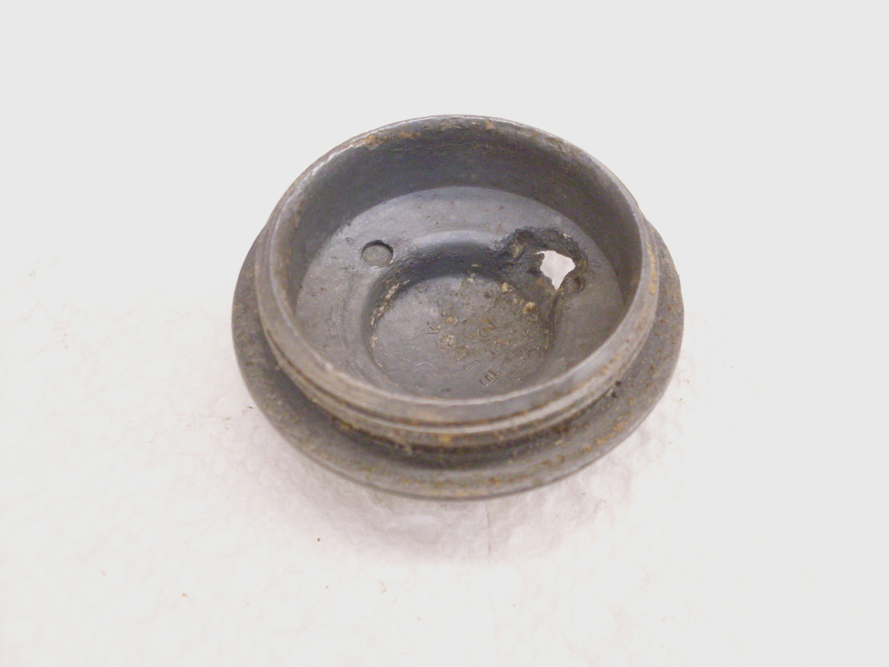
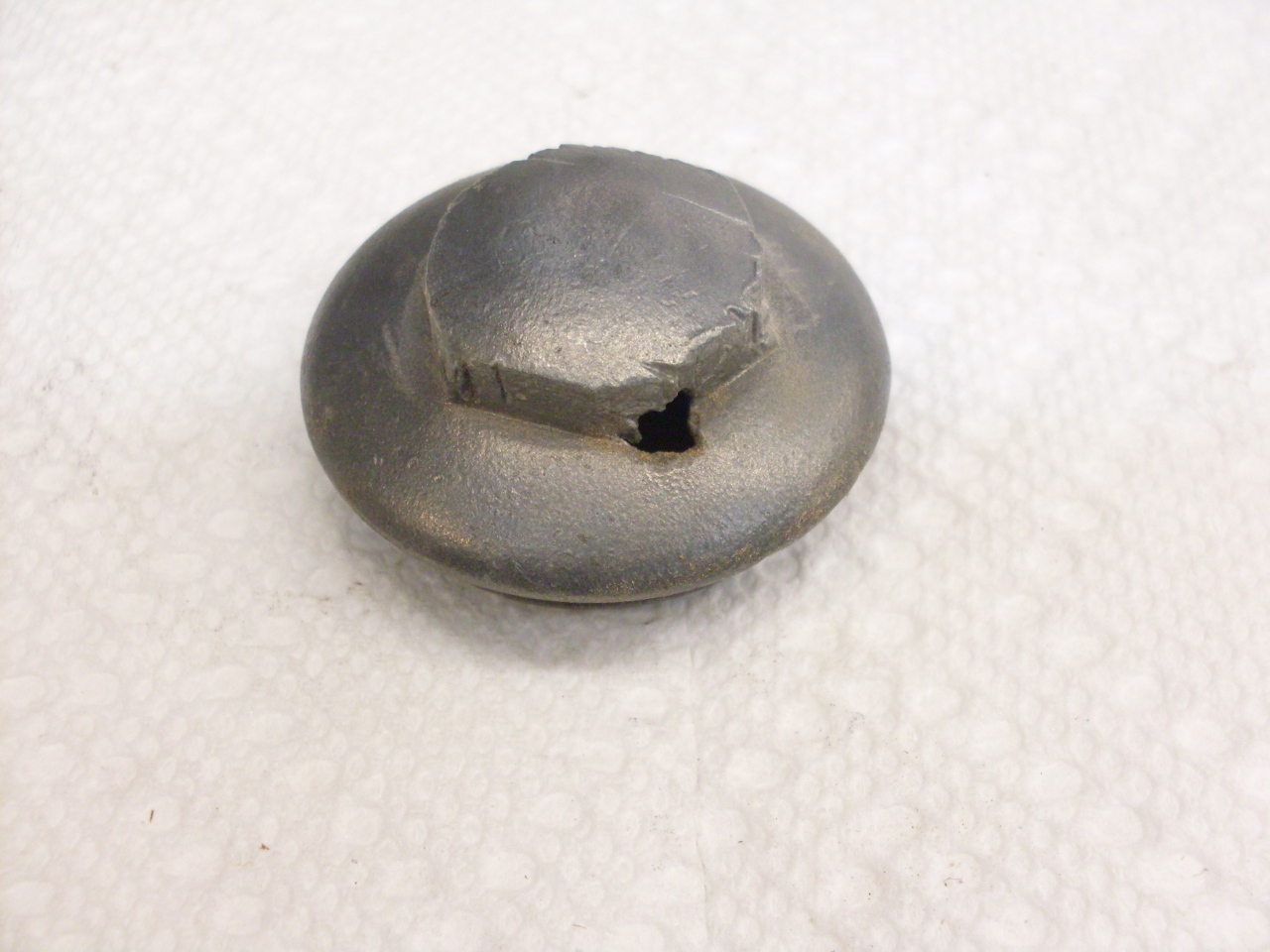
I
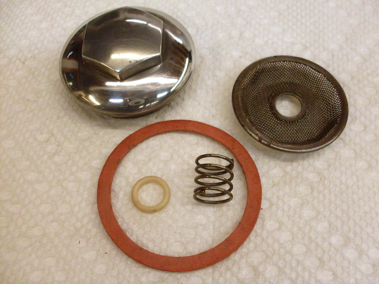
decided not to try. Here are the parts of the sump, with a new
cap. The screen is what Triumph calls a "filter". The O
ring is interesting. The parts manual shows it going above the
spring (which holds the "filter" down against the cap), next to the
flange on the sump oil scavange tube. There is nothing to seal
there, and I can see no earthly purpose for the O ring. A query
on a couple of Triumph forums didn't turn up any explanation.
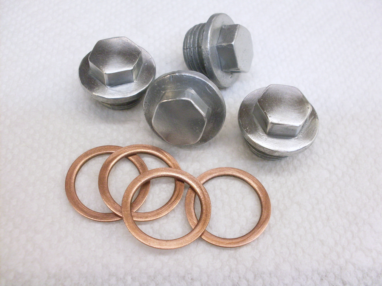
The
rocker box plugs, which close the feeler gage holes on the rocker
boxes. Those are copper "crush washers", which technically aren't
supposed to be re-used. Many people do, though. These are
probably original on the bike, so I did get new ones.
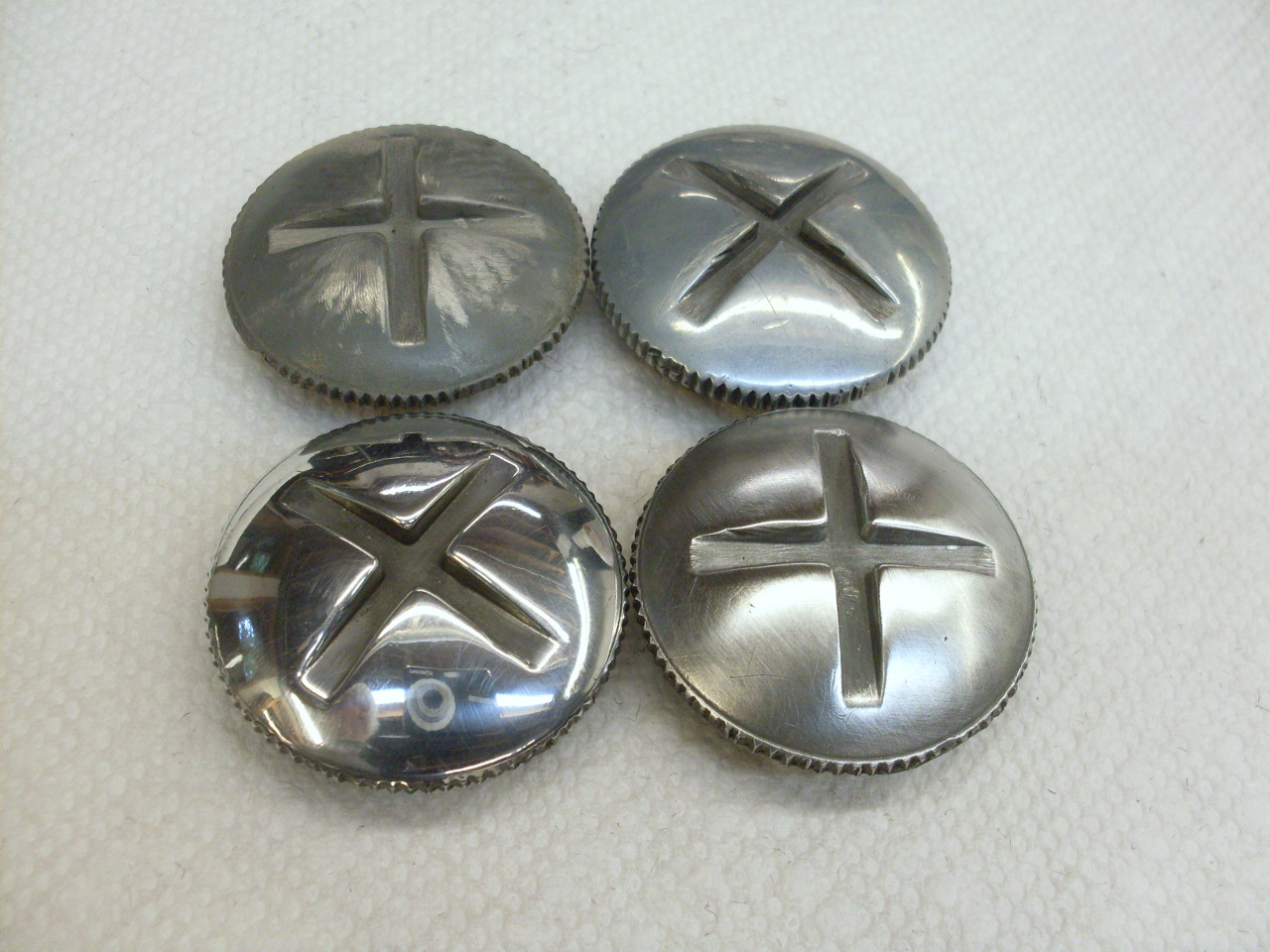
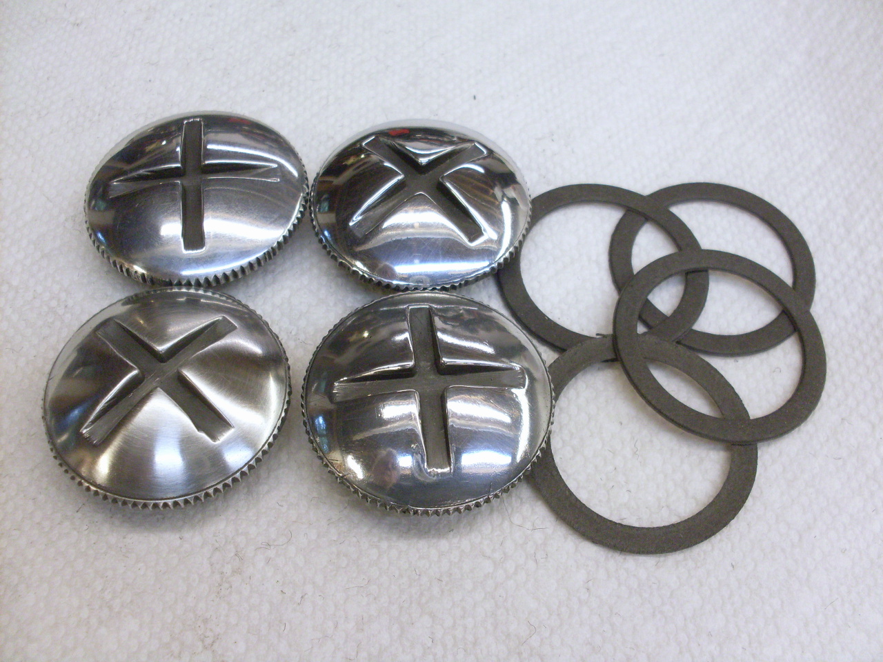
The
rocker inspection caps are pretty visible items, so I spent a little
tiome cleaning them up. The first pic shows the stages of cleanup
and polishing. It's really only about ten minutes from one stage
to the next. The second pic shows one of the caps brought back
from a high polish to more of a satin finish. I like this better
and will do them all this way. It's moot in a way, since the
sheen doesn't last that long, especially with some tempterture cycles.
There
are three of these covers onthe engine--the clutch adjustment cover,
the gearbox filler, and the primary chain inspection cover.

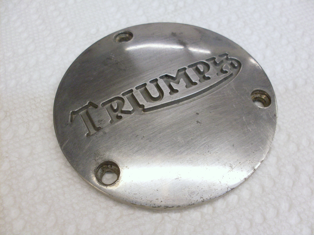
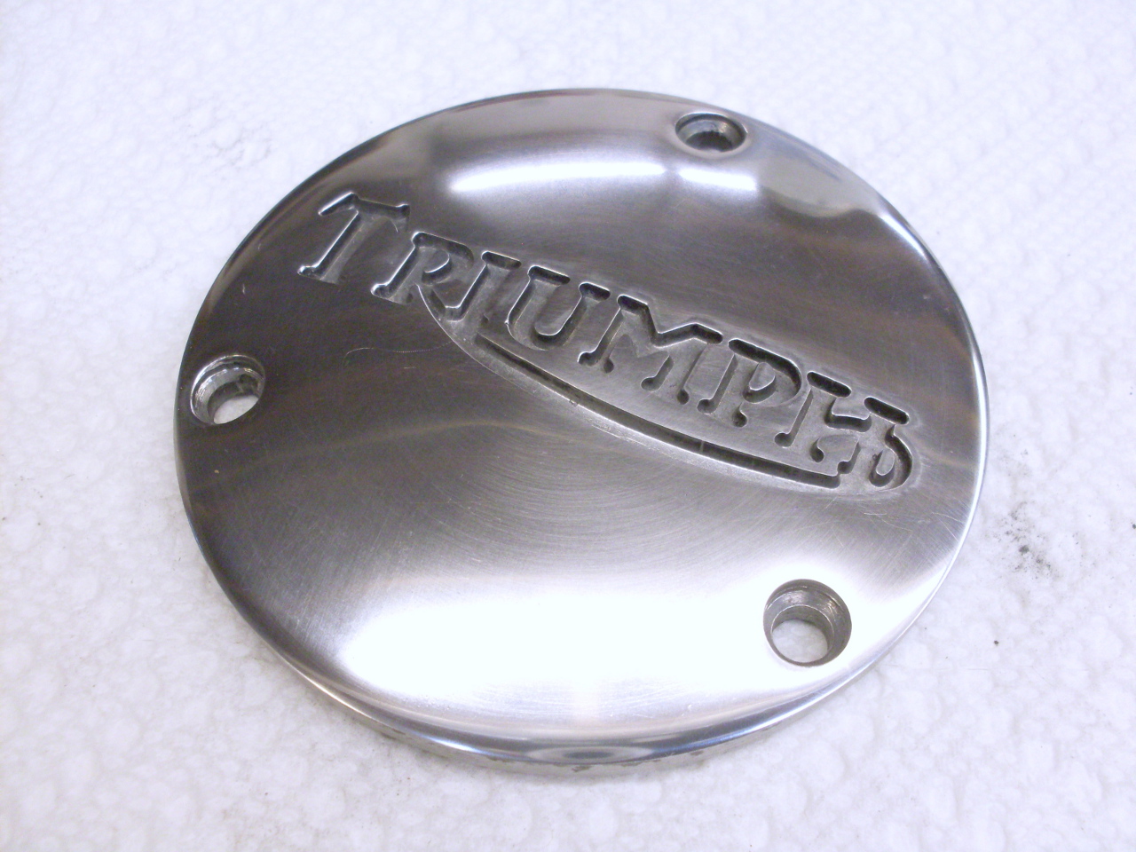
The
rotor cover is a pretty visual part of the engine, and I try to take
some pains on items with a logo. This shows the stages starting
from the first pic where the cover has just been washed and cleaned
with a little steel wool. This is an alloy which won't really
take a high polish, which is fine with me. There is something
going on with the screws for this part. The part number in the
parts manual doesn't seem to be available anywhere, but they are
apparently just 2BA oval head. I think they were chrome plated
though, which means that tank badge screws should work OK.


Getting
really close to starting this puppy up. First there is the small
problem of getting it up a few stairs and out of my basement.
To other pages
Comments to: elhollin1@yahoo.com