December, 2011
Instruments
I pulled out the speedometer and tachometer a couple of weeks ago to
try to decide what to do about them.
They are both the original, stock instruments that came on
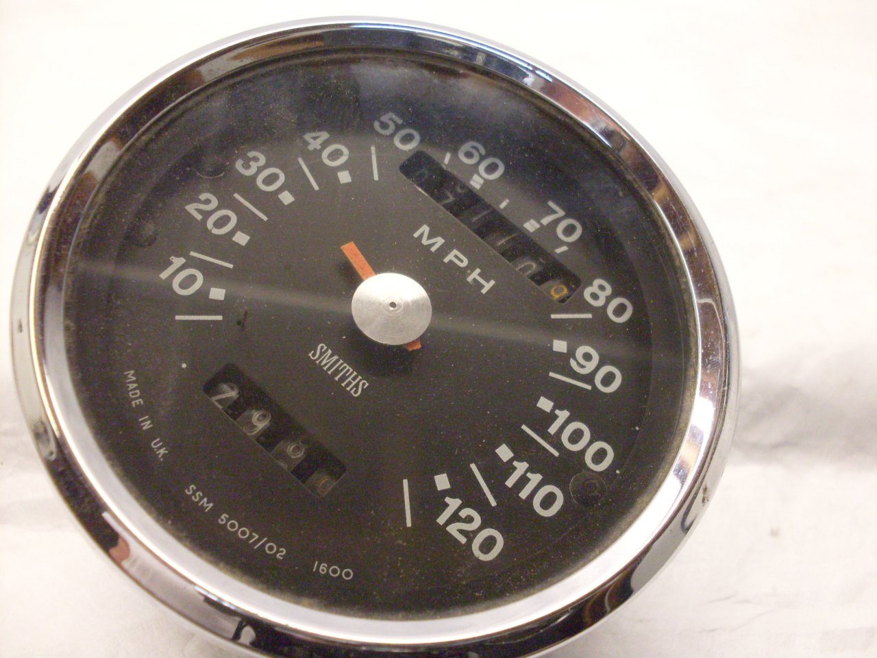
the bike. The speedometer was in bad shape. It was
weatherbeaten, the pointer was broken off, and both odometer
assemblies were crooked in their windows. The
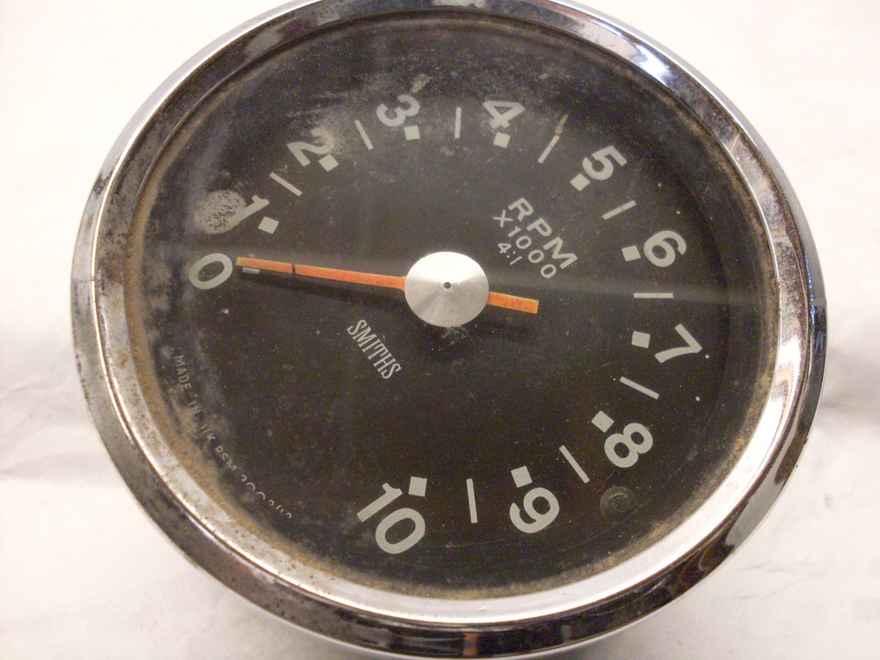
tach looked a little better, but I seemed to remember that it
was very jumpy the last time I rode the bike.
I had several choices regarding the instruments: Aftermarket
reproduction units are apparently available. There are also a
number of outfits that would rebuild these units, or accept my units as
cores, and sell me rebuilt ones off the shelf. The research I
did showed that neither of these was necessarily a bad choice.
The other option was to try to rebuild them myself. Since the this
option is more in keeping with the spirit of the entire
project, this is the route I chose.
I
did some research, and found half a dozen web sites that have some
information about it, and also a book on the subject. I
ordered "Magnetic Speedometer Repair"
by Graham Blighe. Though I was already fairly familiar with
working on small mechanisms like this, the book probably helped me
avoid a pitfall or two.
Following is the story of what I did to my instruments.
It turns out that one of the most difficult steps is the first one:
getting the crimped bezels off. The sources say
that if the bezel is carefully pried off little by little around the
perimeter with a small screwdriver, that the bezel might be reused.
Once I got the hang of it, it wasn't too bad. When I was
finished, those bezels didn't look like anything I'd want to reuse.
Most of the pictures that follow are of the speedometer. The
tachometer is identical inside, except that it doesn't have the
odometers.
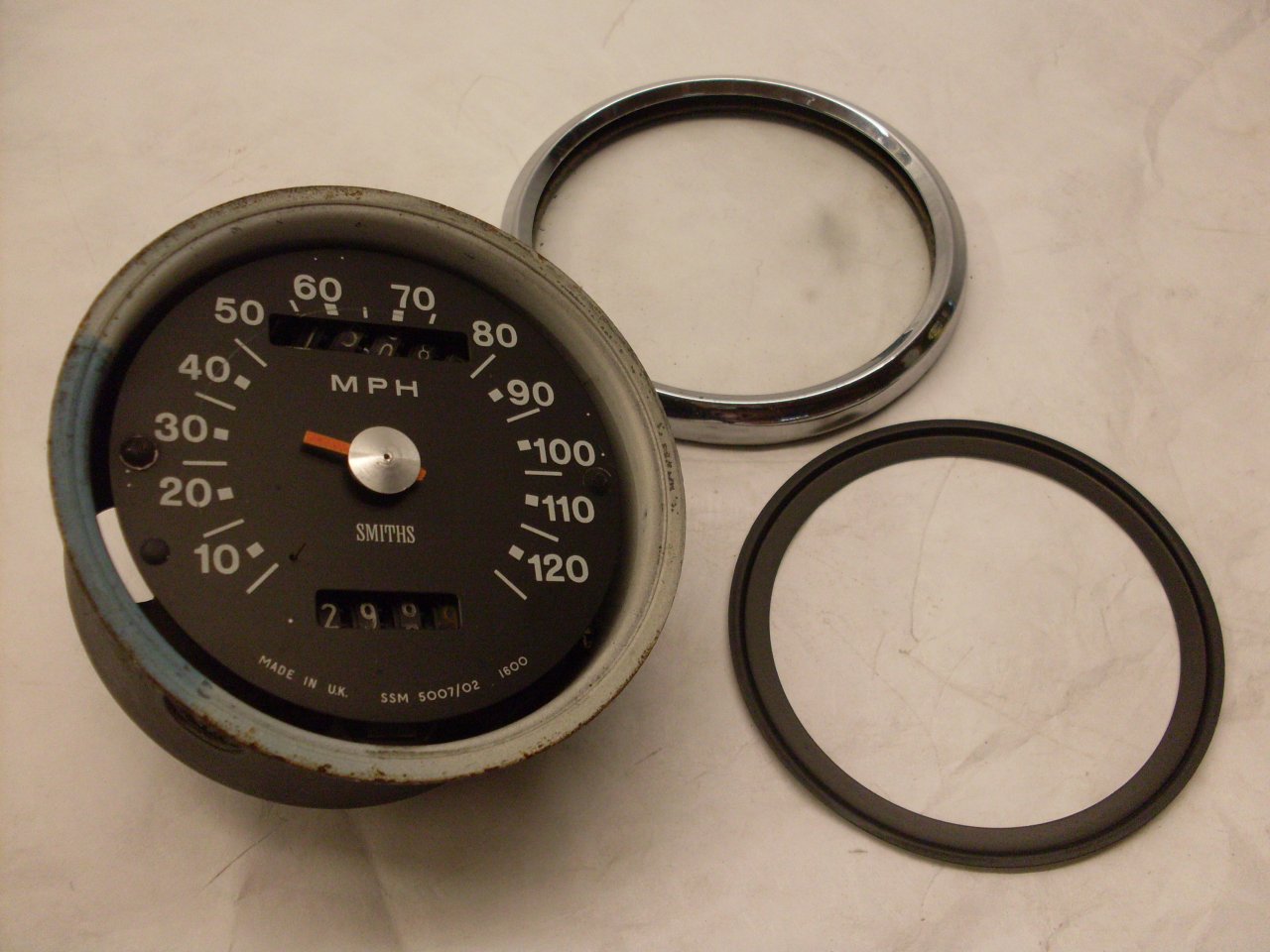
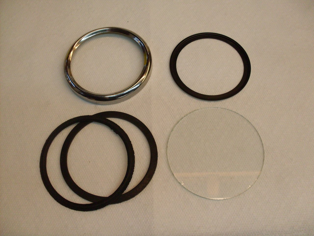
There is a triangle-section rubber seal between the bezel and the
glass, another rubber seal under the glass, and a circular mask piece
that hides the space at the edge of the dial, but allows light from the
internal bulb to illuminate the dial. The rubber seals were
hard and brittle, and basically fell apart on disassembly.
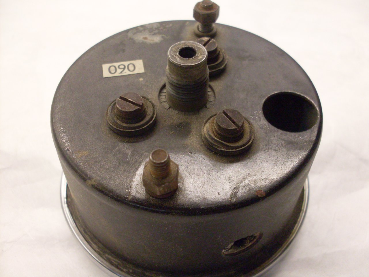
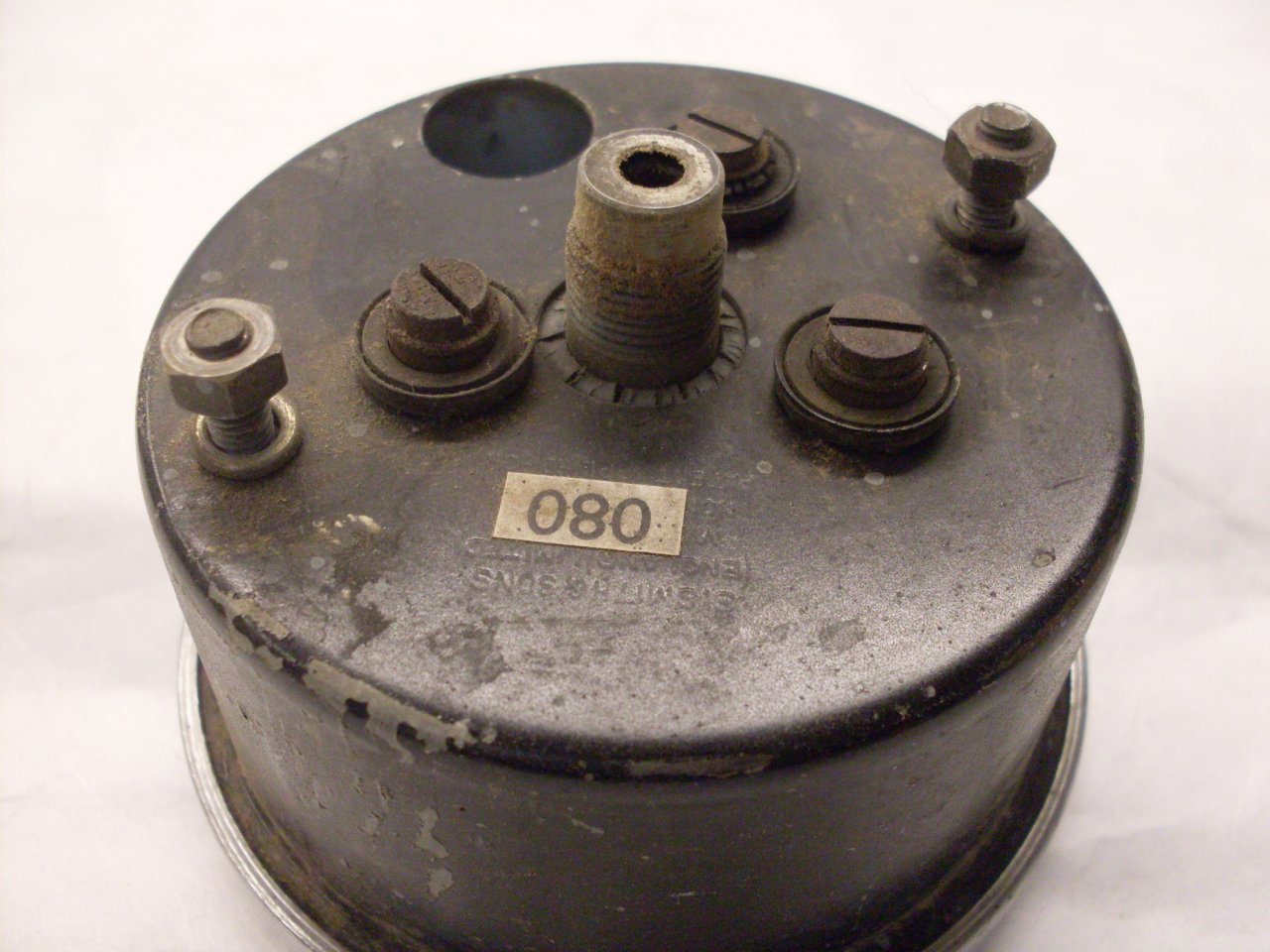
Undoing the three screws on the back of the case, the mechanism can be
lifted out. When I did that, the main odometer assembly fell
out onto the table.
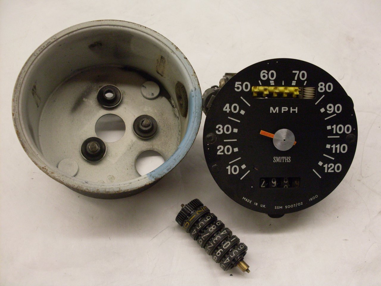
The internal mechanism can look a little intimidating at first, but it
is really pretty simple.
After the pointer needle (what was left of it) was pried off, the dial
came off by drifting out the center keepers of the two small reusable
plastic rivets. This reveals the internal mechanism.
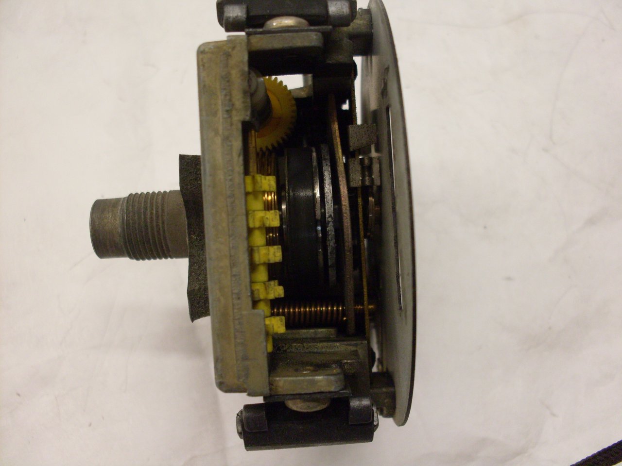
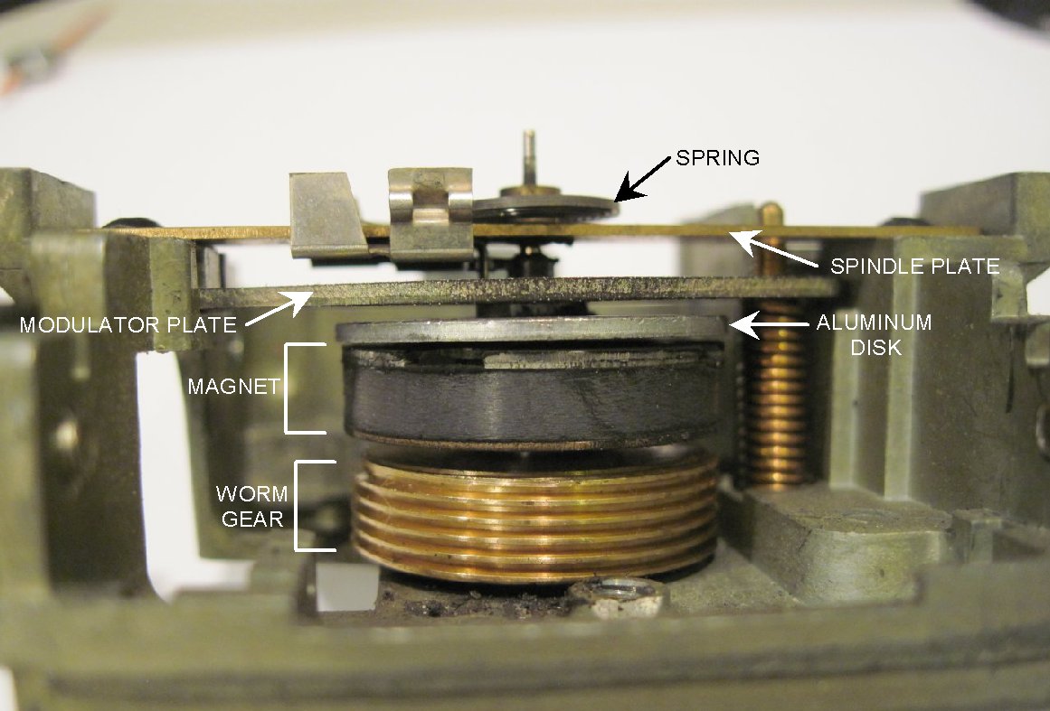
All magnetic speedometers and odometers I've had apart employ the
same basic principles, and here's a synopsis of how it works (see
annotated pic below): The speedometer
(or tach) cable connects to the bottom of the casting, and the cable's
inner flexible shaft turns the input spindle of the instrument,
which has
both the brass worm gear and the dark grey magnet pressed onto it, so
the gear and the magnet both spin at the same speed as the speedometer
cable core. The worm gear drives the odometers through a chain of
plastic gears.
Just above the magnet, but not touching it, is an aluminum
disc. The disc is on a smaller spindle that extends up through
a hole in the brass spindle plate, and down into a recess in the center
of the magnet. The hole in the spindle plate and the recess
in the center of the magnet serve to locate the spindle so that the
disc
is always parallel to, but not touching, the magnet. The
upper part of the disc spindle has a collar pressed onto it above the
spindle plate such that the disc and spindle are hanging from
the plate, supported by the collar. The collar also
holds one end of a spiral return spring so that when the disc turns, it
winds the spring.
Now, even though aluminum is not magnetic, it is conductive, so when
the nearby magnet is spinning, electric currents start to flow in the
aluminum disc. These currents create their own mangnetic
field which reacts with the field of the magnet such that the disc
tries to spin with the magnet. The torque created by the disk
trying to follow the magnet is opposed by the spring. Since
the torque on the disc goes up as the magnet spins faster, the result
is that the disc rotates against the spring in proportion to how fast
the magnet is spinning. The indicator needle is attached to
the spindle, so the needle shows how far the disc rotates.
The steel modulator plate is provided as part of the magnetic circuit so that the strength of the
magnetic field that the disc sees from the magnet can be varied.
If the modulator plate is moved closer to the disc, the field
is stronger, and the torque for a given magnet speed is increased,
Adjusting the modulator plate is how the speedometer (or
tach) is calibrated. There is a screw accessible on the back
of the main casting that moves the modulator plate against
the spring that can be seen to the right of the magnet.
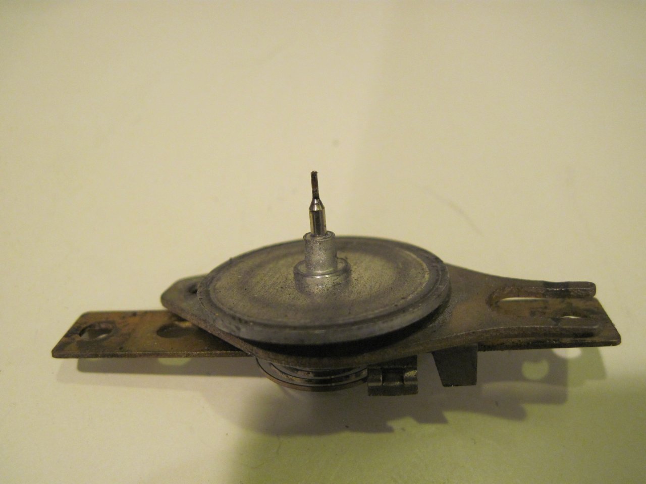
Here are some other views of the disc assembly (disc and spindle,
modulator plate, spindle plate, collar and spring) removed. The
assembly is
held to the casting by more of those reusable plastic rivets.

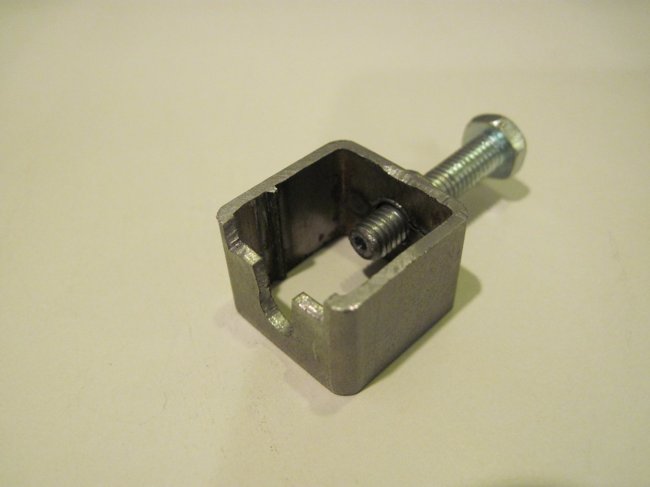
In order to inspect for wear, the disc assembly has to be taken apart.
This is done by pulling off the pressed on collar from the
disc's spindle. Shown is a collar removal tool like those
used by RC model car hobbyists. It inserts under spindle
plate,
and the screw pushes the spindle through the collar.
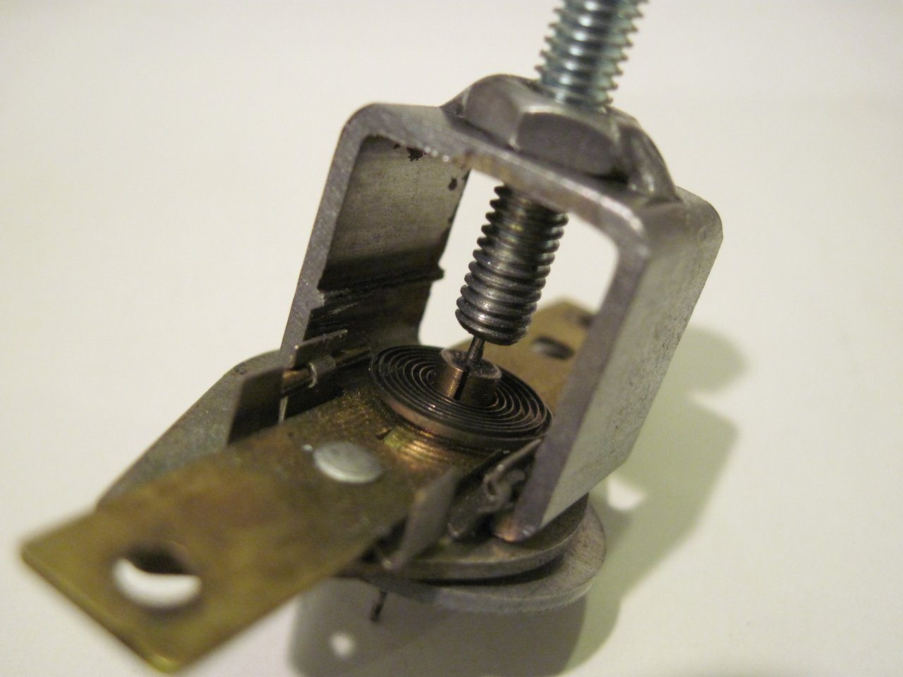
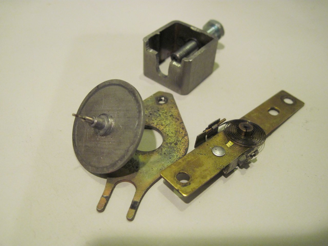
One thing I nearly lost was a
tiny washer under the spring collar on both instruments. In
effect, this is a thrust bearing that takes the weight of the disc and
spindle while minimizing contact area.
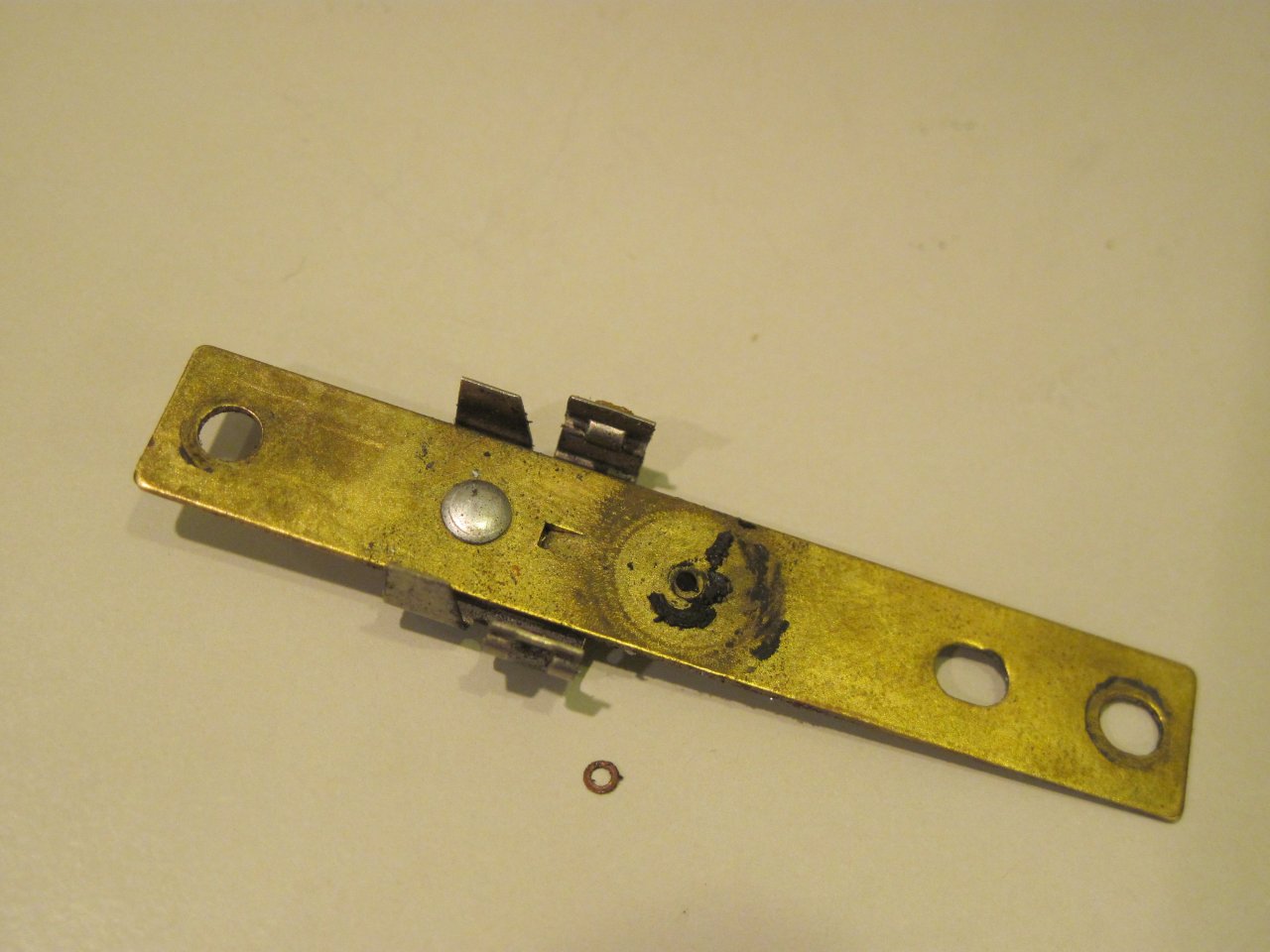
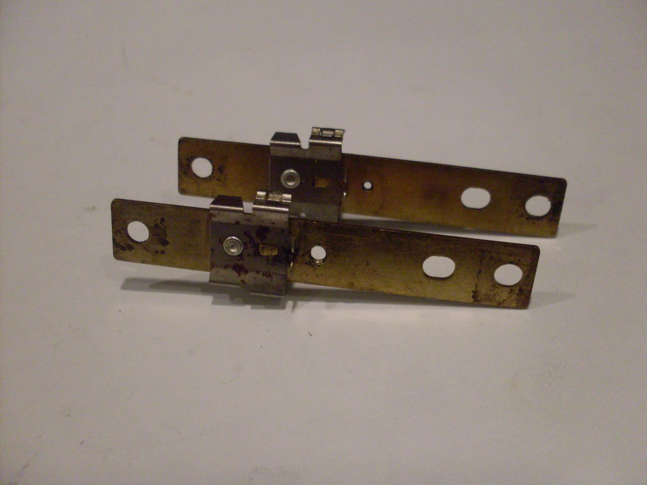
Here is one thing I found that explains a lot. These
are the spindle plates from the two instruments. The hole near
the center of the plate is the locating hole for the disc spindle.
The spindle where it passes through the hole is slightly less
than one mm in diameter, and the hole diameter should therefore presumably be about one mm.
The hole in the bar to the rear is very slightly oversized,
but the one on the front is a little over 2 mm! It was pretty obvious that this needed to be fixed.
I fixed the problem by using some small telecoping brass tubing from a
hobby store. The larger tube measures 0.093 OD, which was very
slightly larger than the hogged out hole in the spindle plate.
A #42 drill is 0.0935, and it made a nice fit for the tubing.
Luckily, the enlarged hole was still centered in the plate, so
drilling was simple.

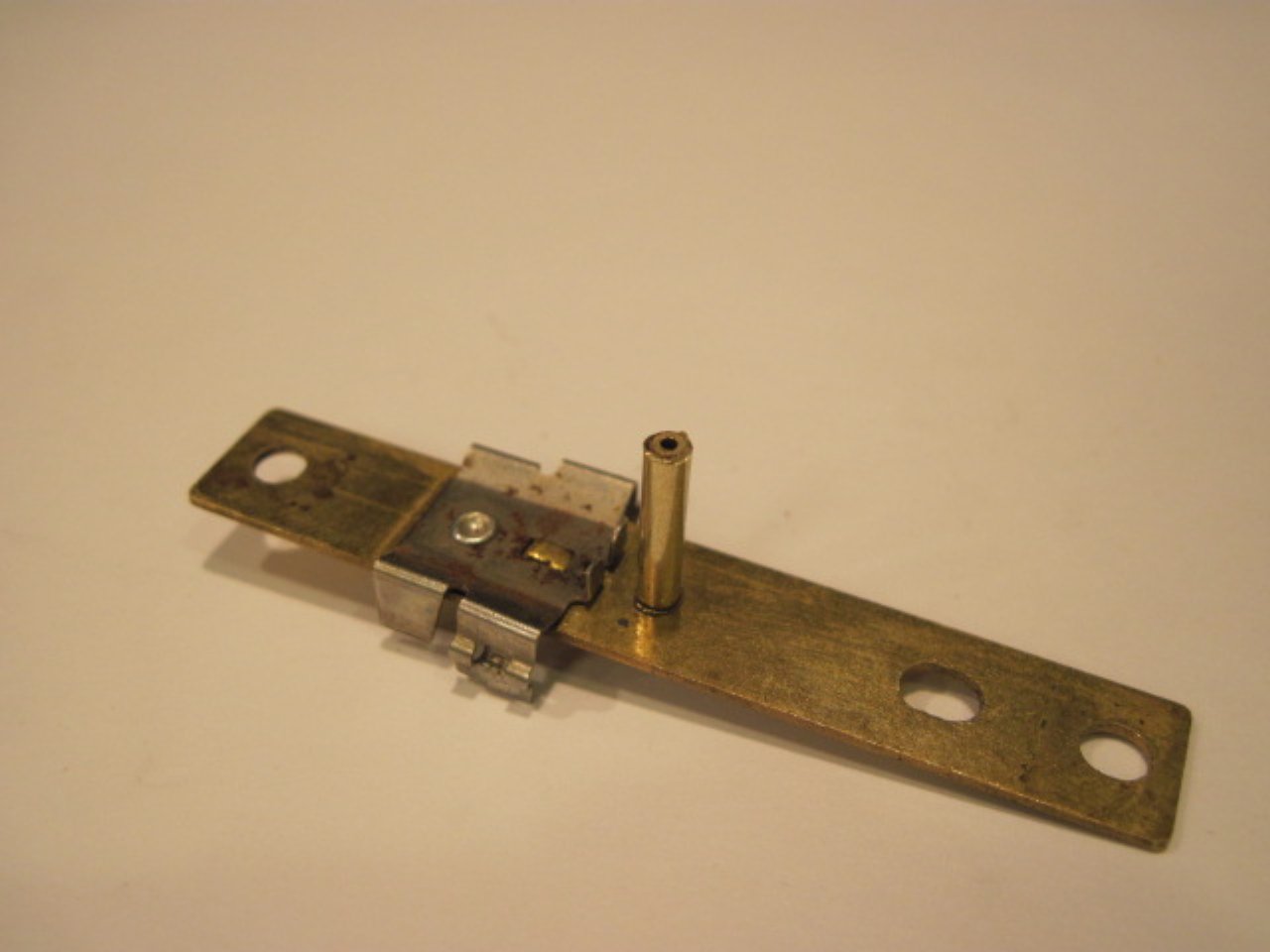
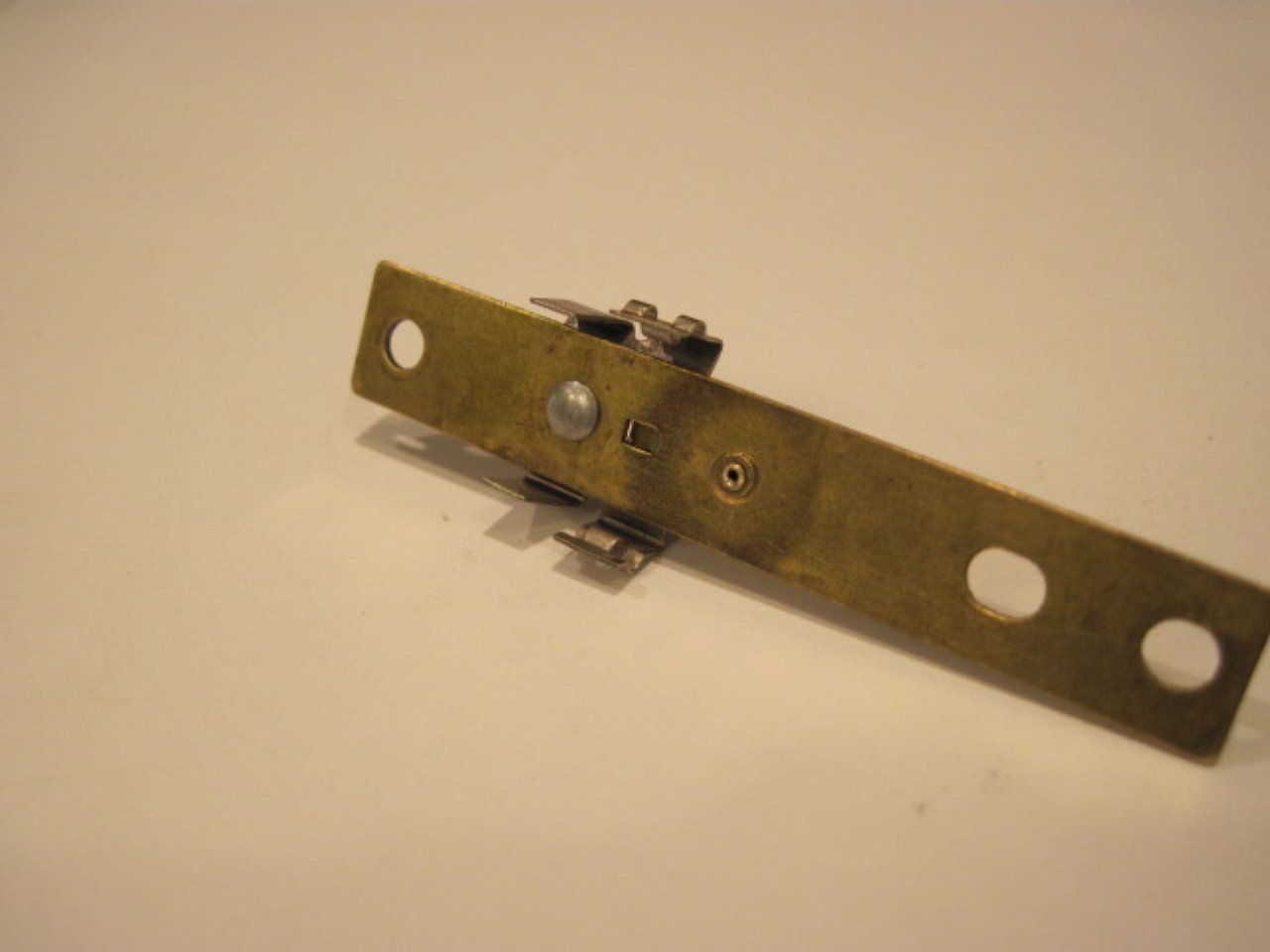
With all the parts being brass, soldering is the obvious way to fix the nested tubes into the hole:
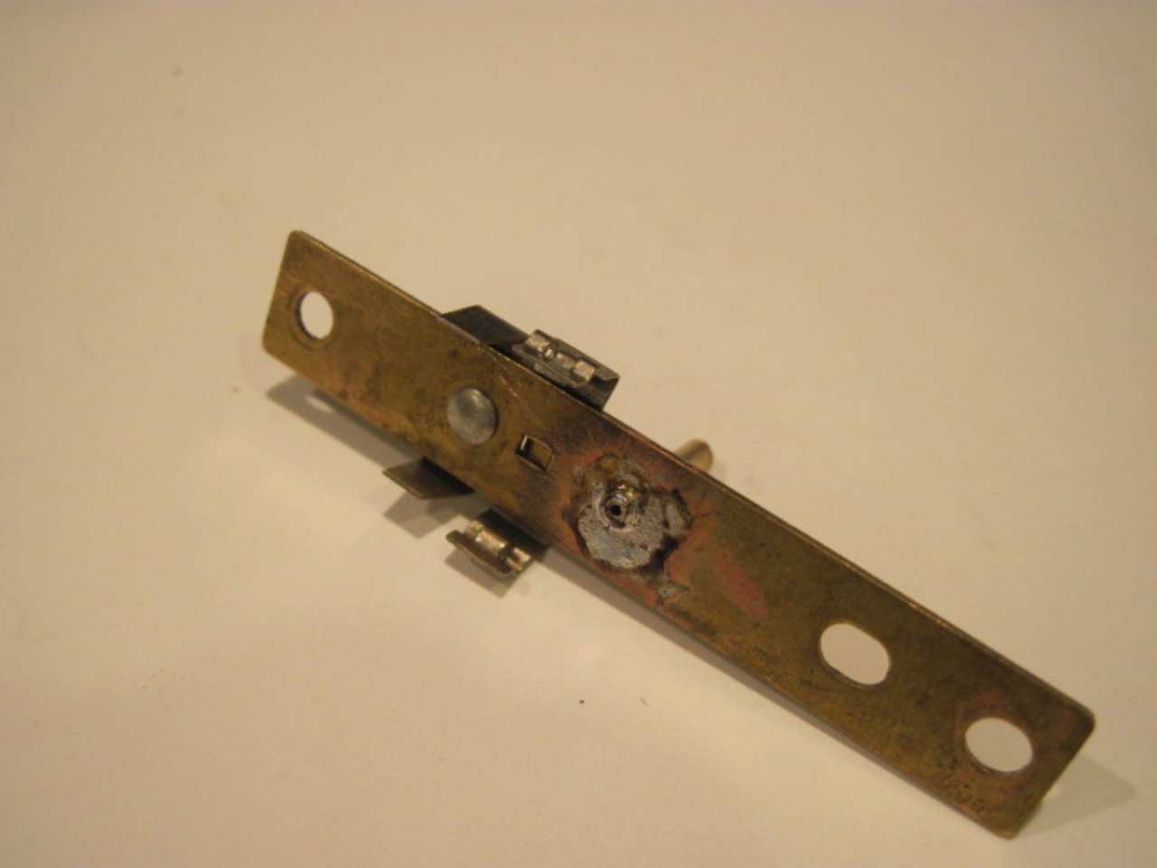
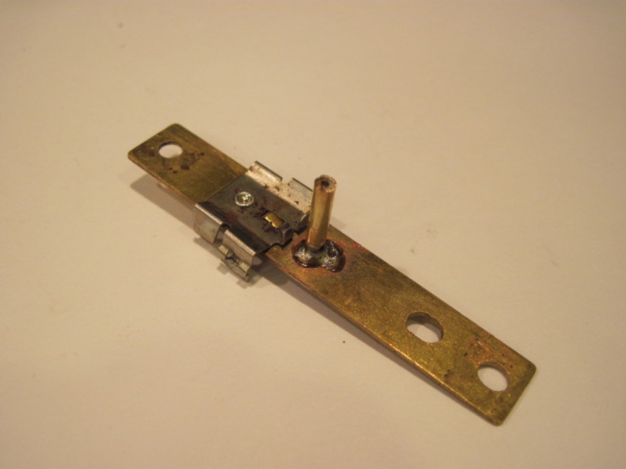
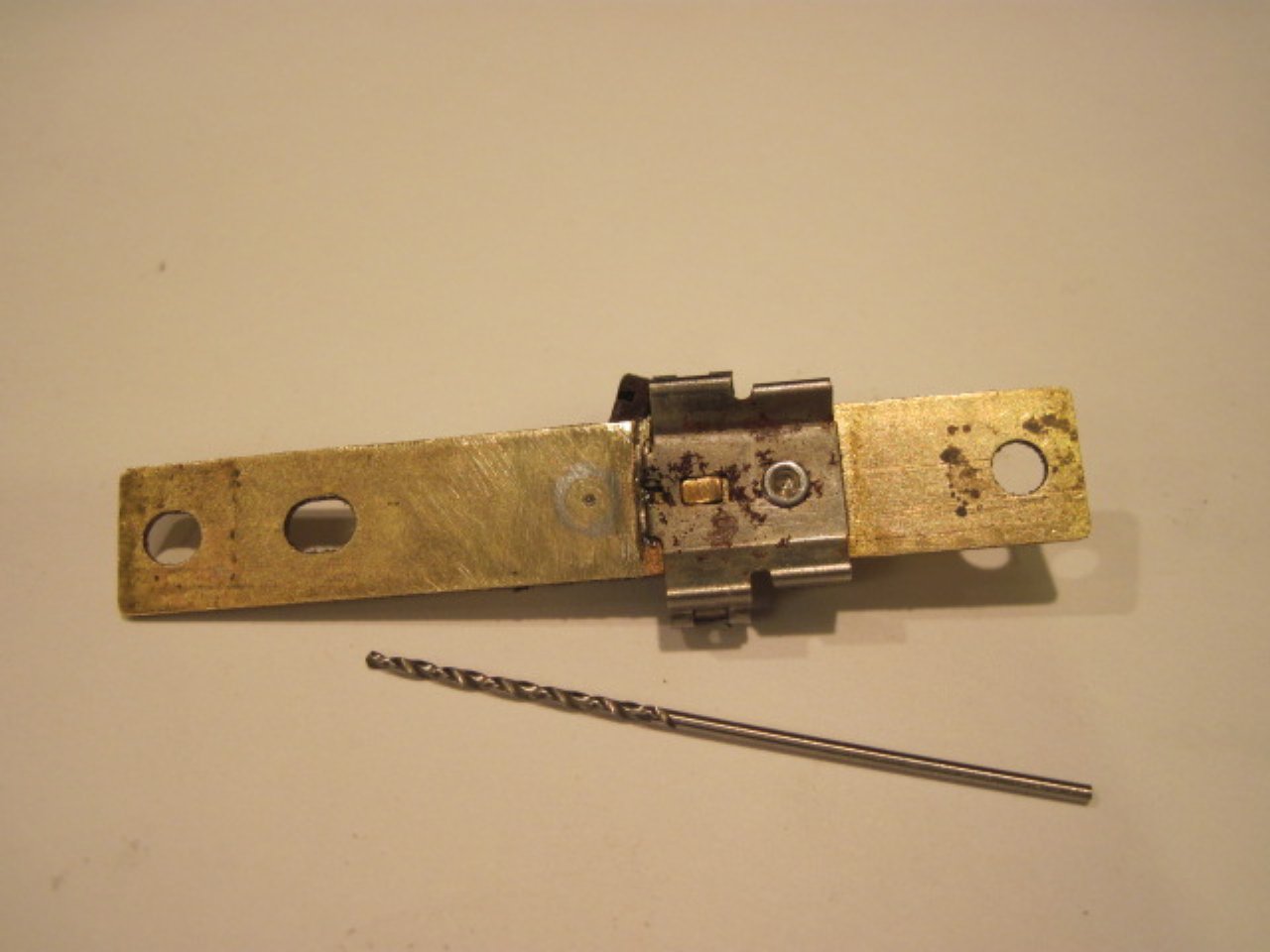
I cut away the excess tube and leveled the surface. I'm not
sure what the ID of the smaller tube is, but it's less than 1 mm, so I
drilled to 1 mm.

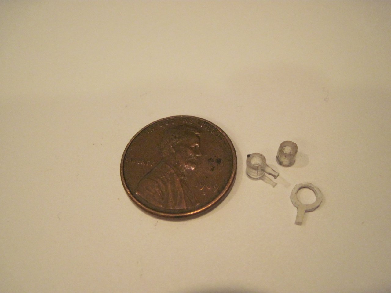
There is one additional part in the disc assembly. There is a
tiny plastic sleeve that goes on the disc spindle just under the
spindle plate. It is a sliding fit on the disc spindle, and it
has
an arm that sticks out into a slot on the spindle plate. The
arm keeps the sleeve from turning with the spindle, so it provides a
little friction to the turning of the spindle, This serves to damp rapid fluctuations in the spindle (and thus the
needle). Well, some regrettable haste led to breaking the tiny arm off one of the sleeves.

One thing that occurred to me was to get a junk instrument and take the
sleeve from it (maybe an indicator needle, too). I found after
calling
around, though, that since even junk units are valuable as cores for
rebuild, no one had junk speedos or tachs around. If I had
looked
harder or if there had been any swap meets handy, I might have found
one, but I took another path and had a fixed sleeve an hour later.
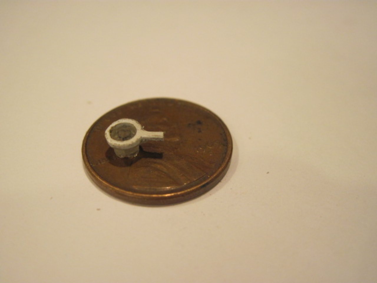
The OD of the sleeve is about 0.062", so a 1/16 drill through
an old credit card, some Exacto work, some cyanoacrylate glue
formulated for plastic, and I had a functional sleeve again.
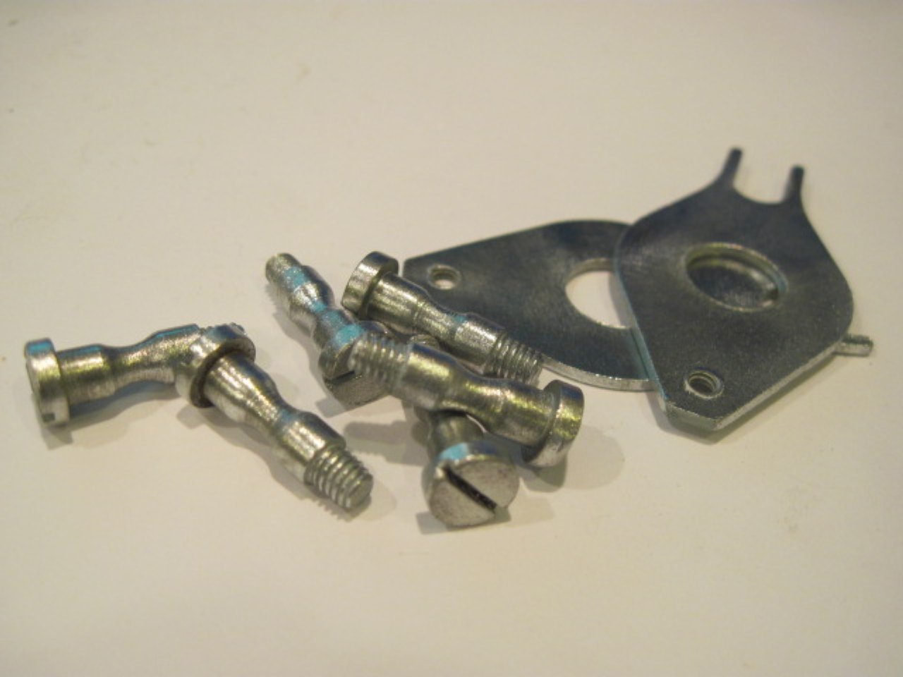
Replated the steel modulator plates and other steel parts:
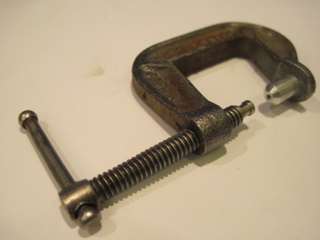
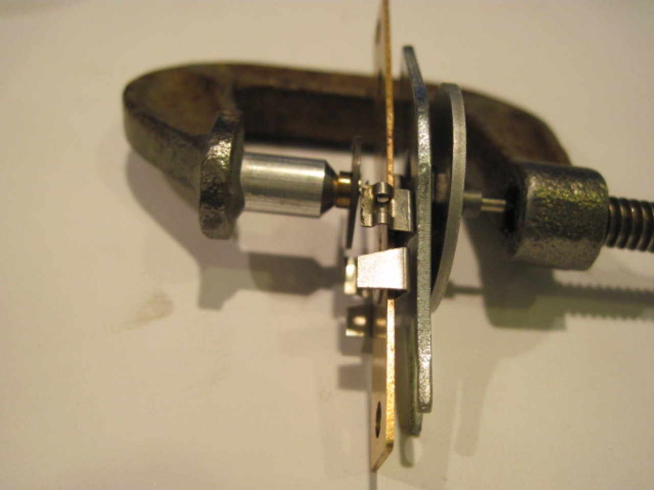
Now I could put the disc assemblies back together. The
modified C clamp tool helped press
the
spring collar back onto the spindle in a very controlled way. The collar should go on
far enough so that there is no more than a few thousandths of vertical
play in the spindle.

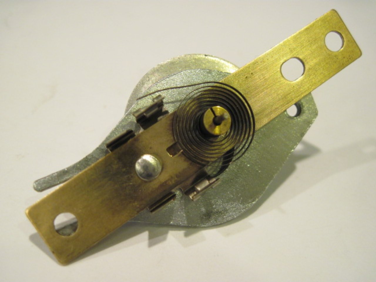
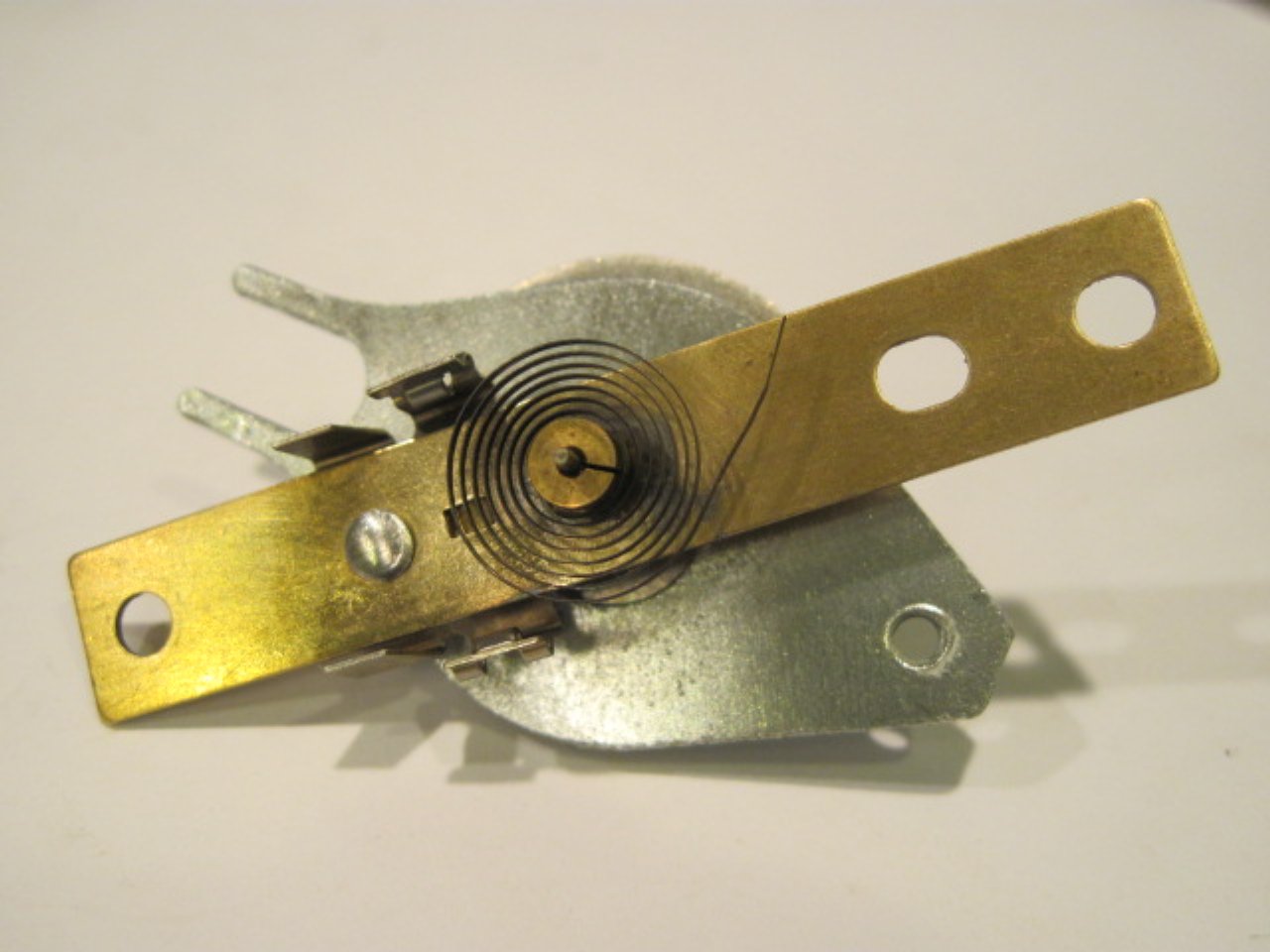
The disc assembly ready to go back on the main casting:
There was one more bit of unpleasantness in the speedometer to take
care of. The main odometer assembly had come loose from its
moorings, but this was really just because there wasn't enough of a
deformation of the metal over where the axle of the assembly
fit into the main casting. I replaced the odometer
and put a little RTV over the recesses to hold it in.
The trip odometer was a different story. First,
this didn't look right:
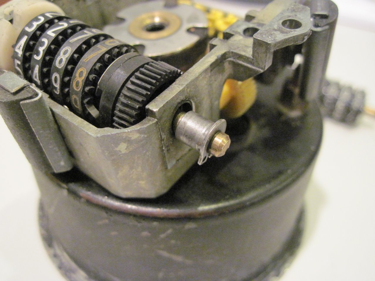
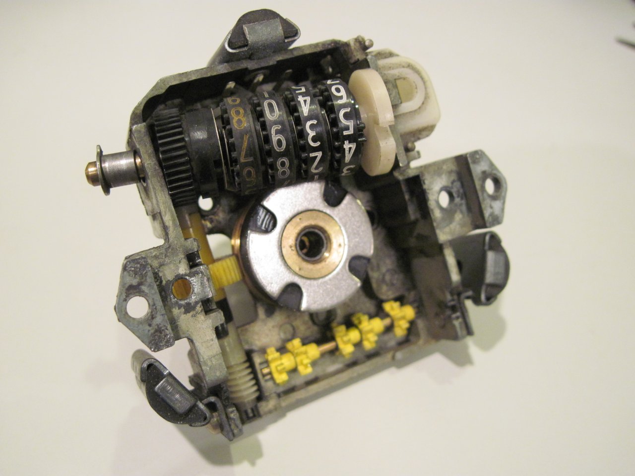
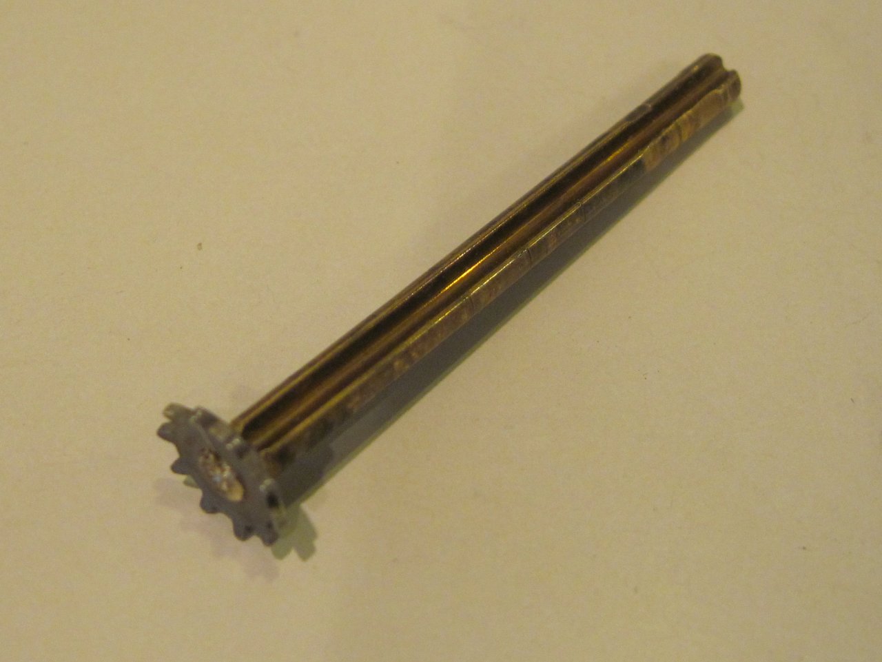
Took the trip odometer assembly out, then took it apart to see how it
worked. There was a while there where I was sorry I did that.
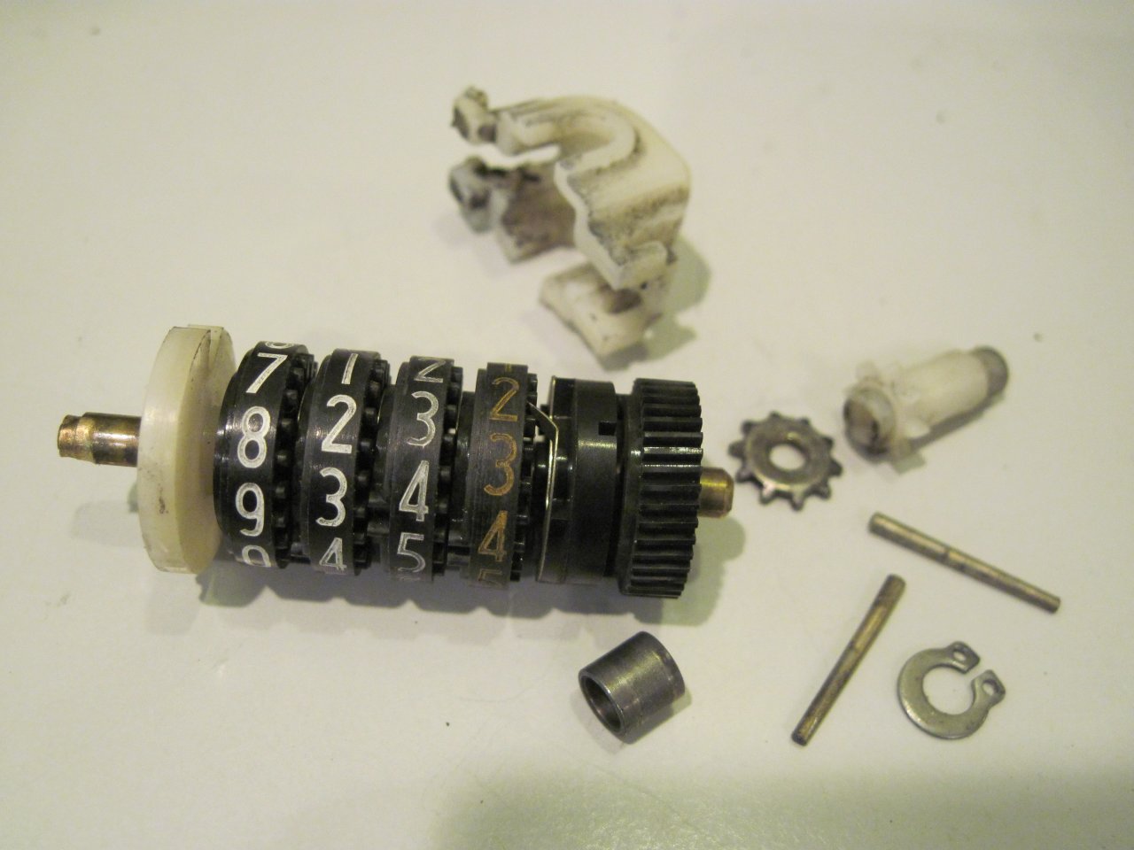
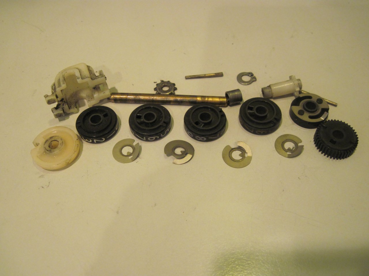
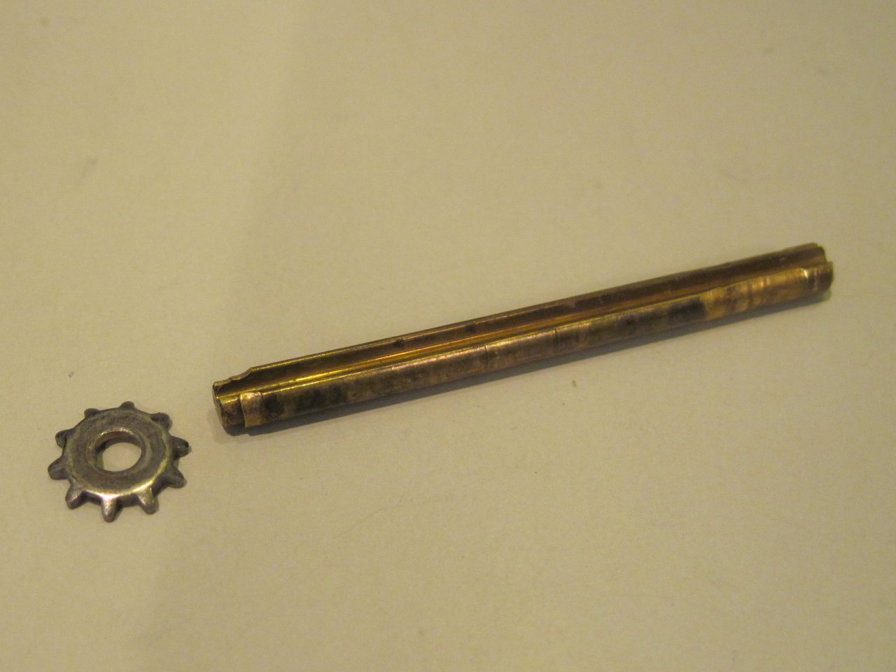
The problem turned out to be that this shaft is supposed to have that
toothed wheel peened onto the end of it, and the wheel had fallen off.
Luckily, it wasn't lost, and I was able to fix it back on.
The wheel is part of the reset mechanism.
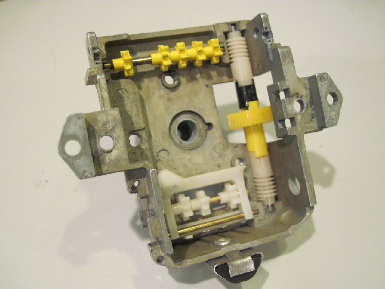
Now for reassembly. Here's the cleaned up casting.
All the plastic gears and such were in good shape, so I
didn't remove them.
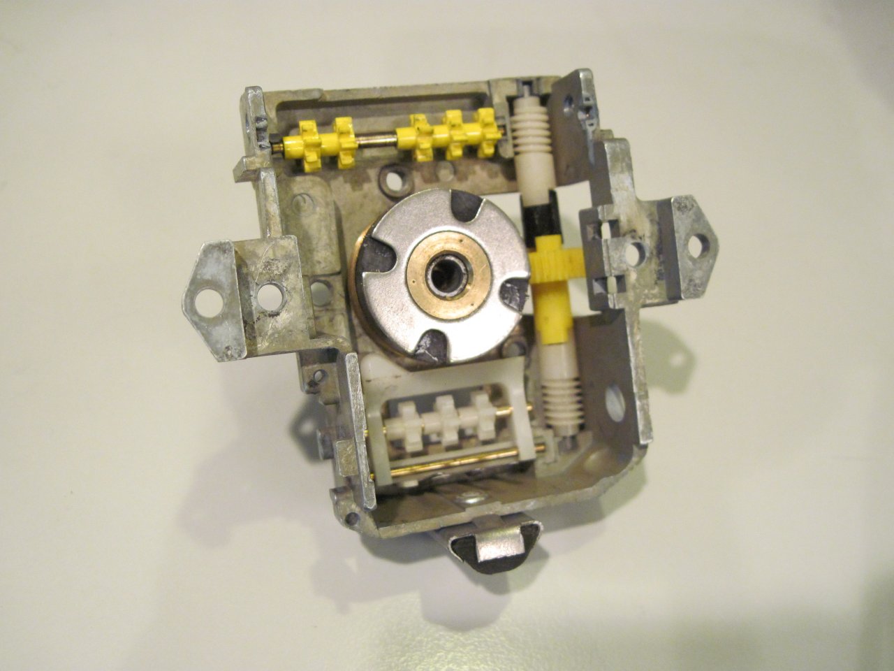
Next picture is with the input spindle installed and the worm gear and
magnet
pressed on. I realized one thing in looking closely at these
parts. I've often heard that if a speedometer or tach inner
cable is too long, it will ruin the tach or speedo by intruding
too far into the guts of the mechanism. At least on these
instruments, that can't happen. First, the square recess in
the input spindle that accepts the inner tach or speedo cable is a
blind hole. Nothing can get into the works through that hole.
What can happen, though, is that since the input spindle has
a flange at the bottom that limits how far it will go in, excessive force on the
input spindle from an inner cable
that's too long would put pressure on the flange, and cause increased
wear. This would eventually but surely cause the spindle to move
upward to contact the aluminum disc. Intermittent contact of the
magnet with the disc causes the pointer to jump wildly, and will
eventually break something.
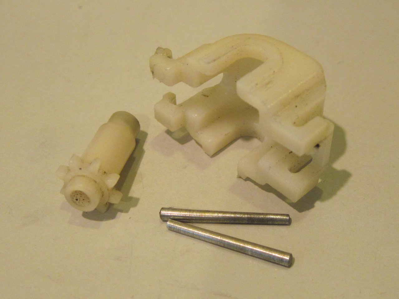
Then the trip odometer. There is a little gearbox that
receives the odometer reset shaft. Smiths loved to use those
little tapered pins to hold things.
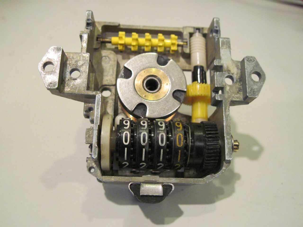
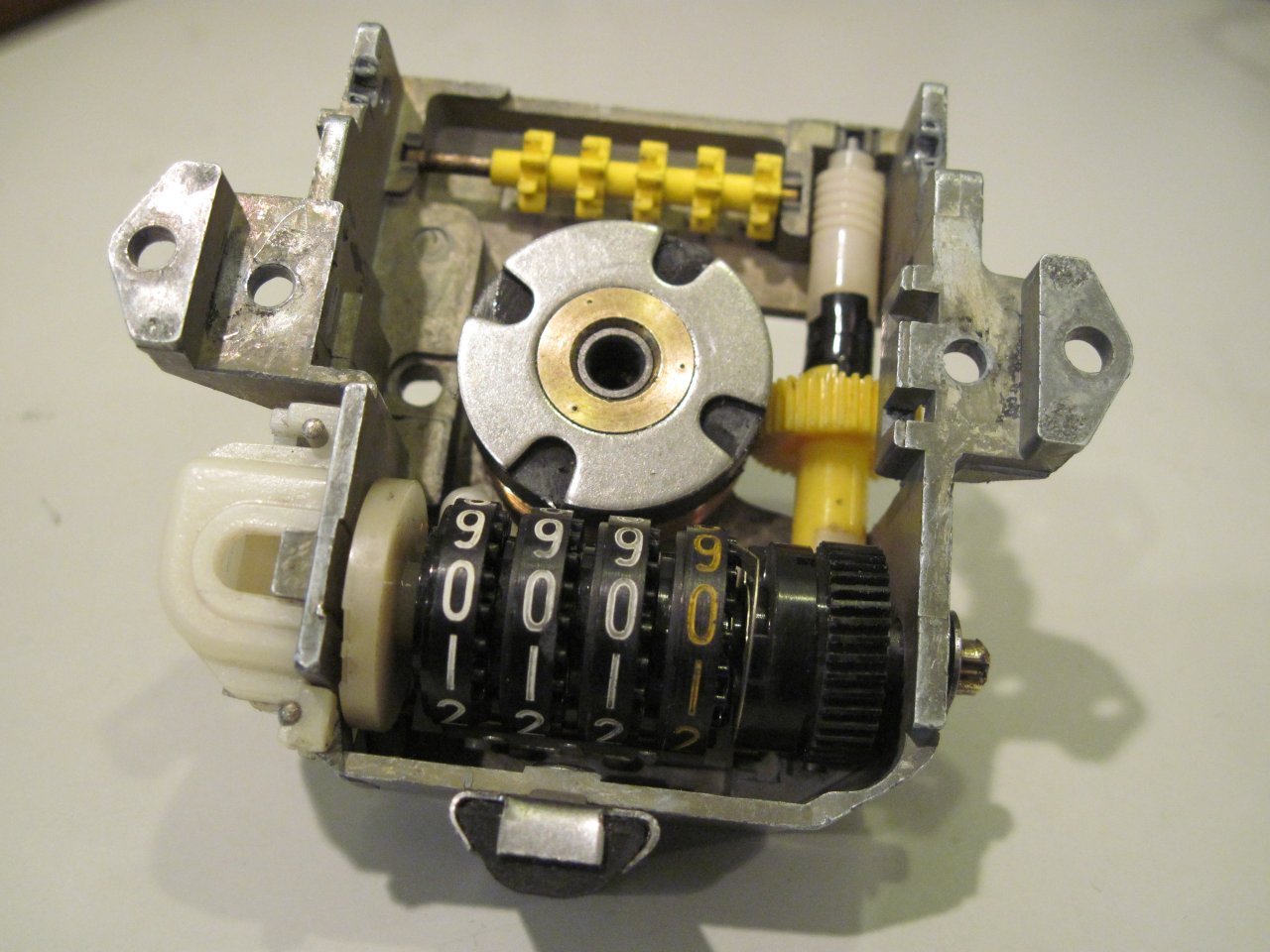
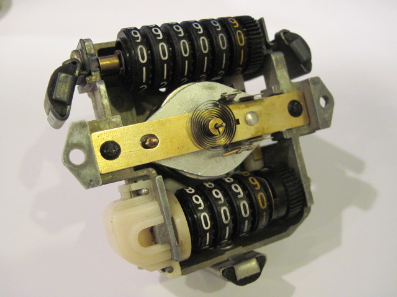
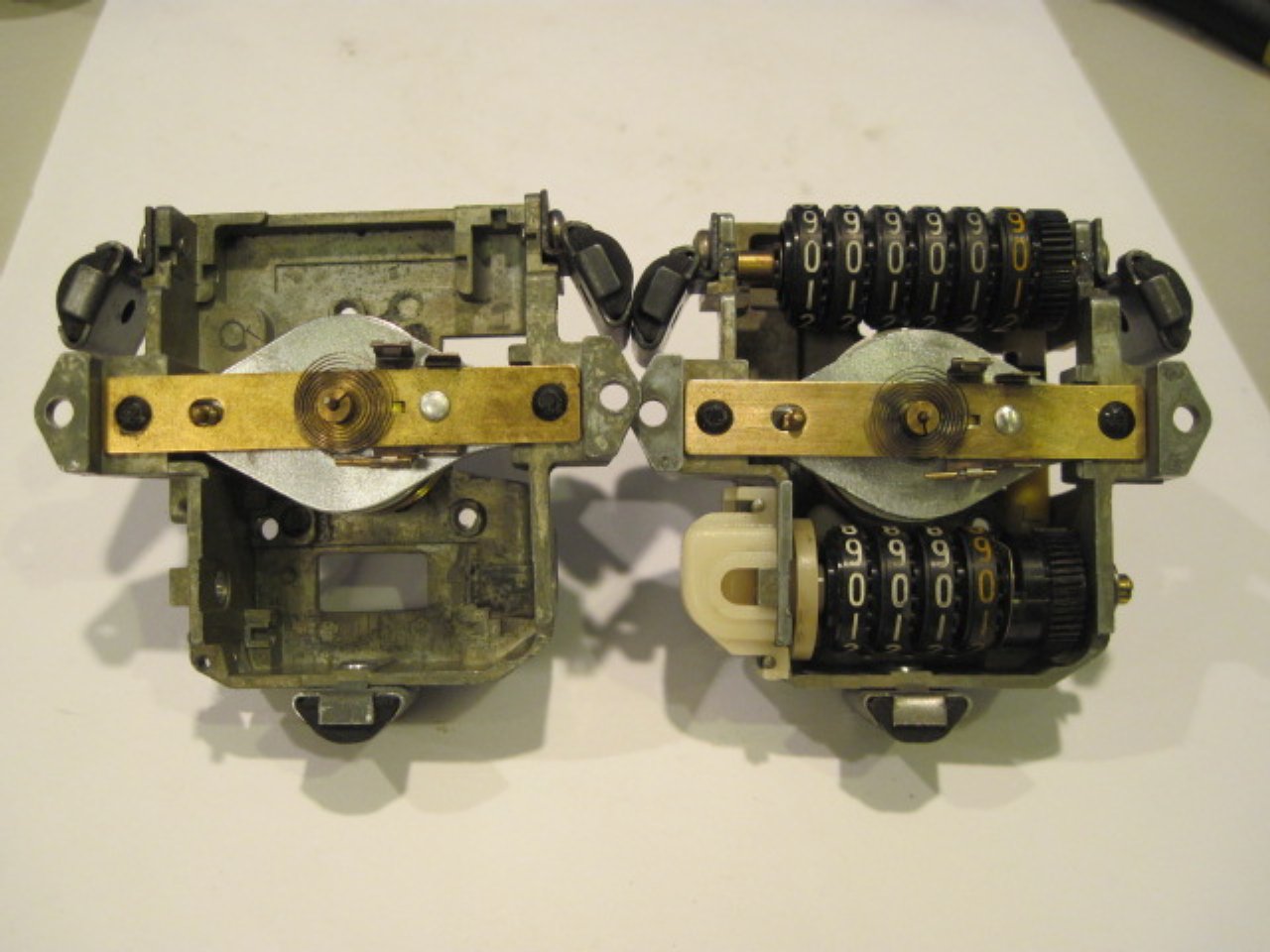
Here is the speedometer with the main odometer and the disc assembly mounted. The
tach is simple by comparison.
Then there was the matter of the broken pointer needle on the
speedometer. Since it didn't look like I was going to find a
junk unit, and I couldn't find anything suitable online, I had no
choice but to try to dummy one up.


The pointers were made of aluminum, about 0.010 thick. I
found some flashing tha fit the bill. I had to buy 10
square feet of it.
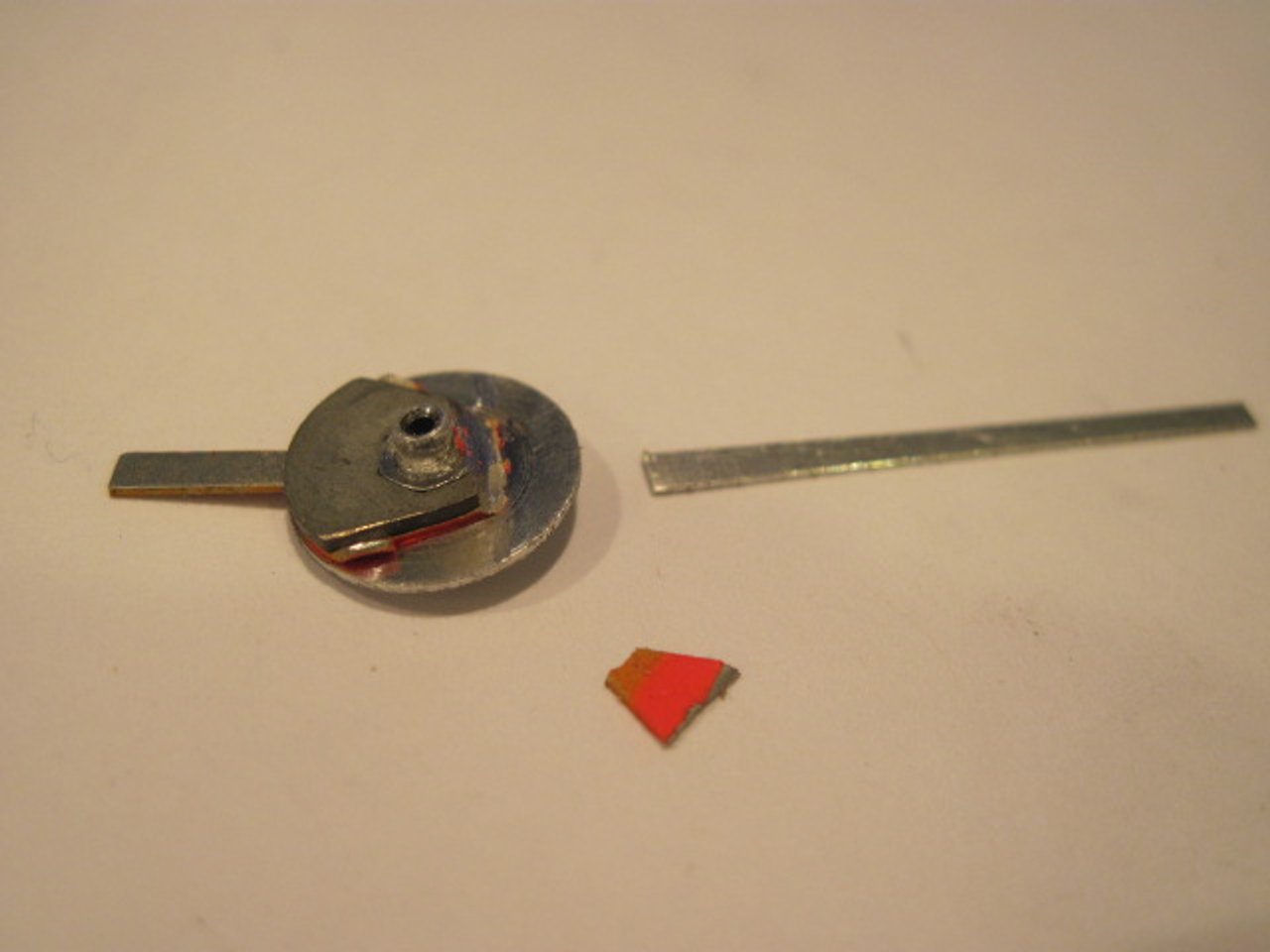
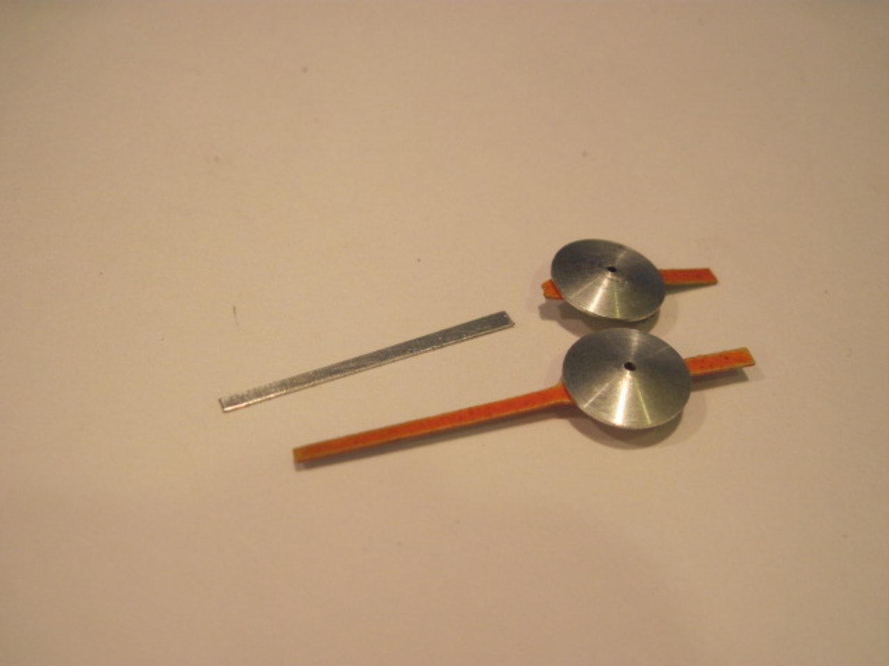
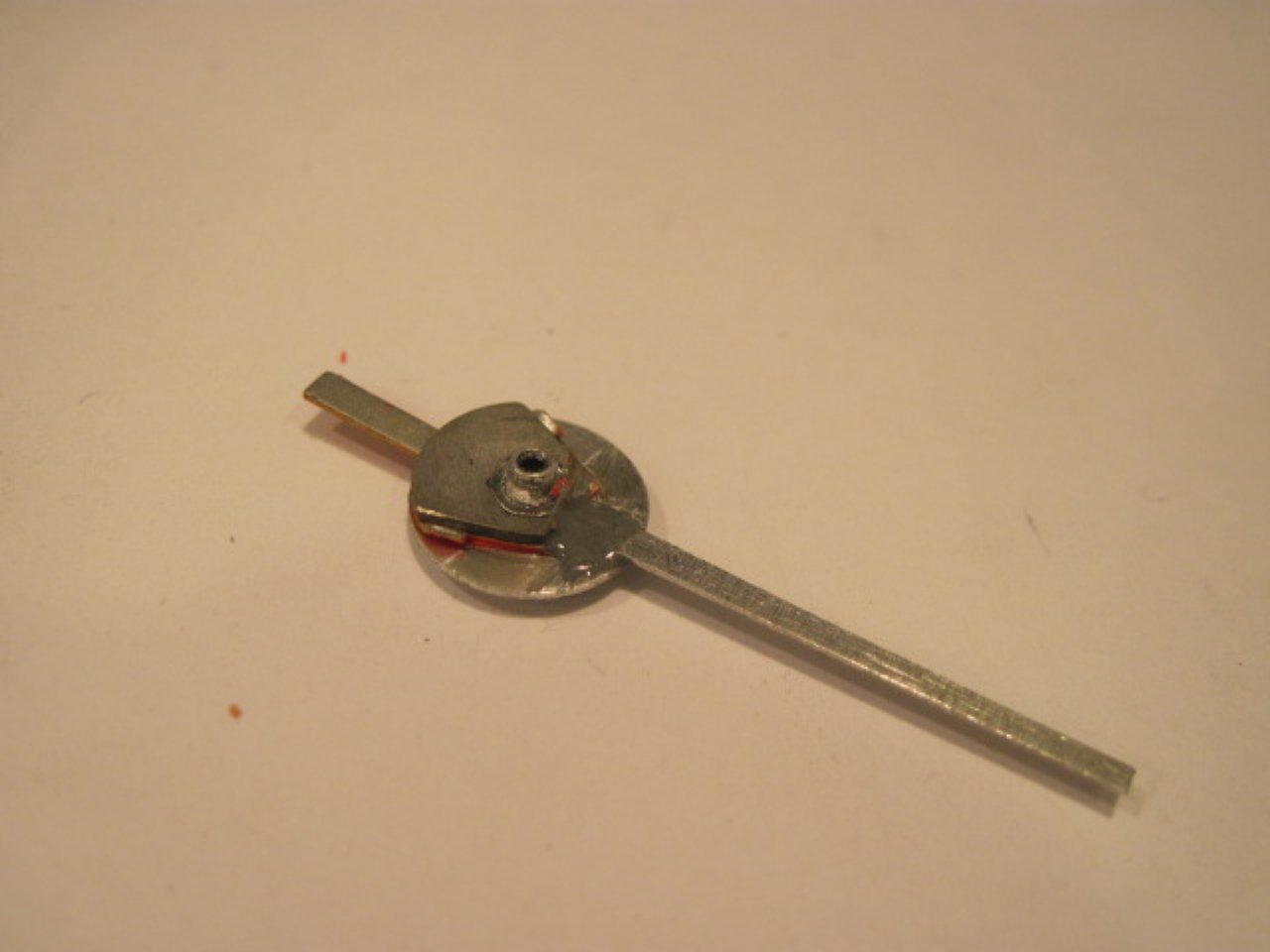
Cut away a little more of the old pointer under the hub, and fastened
the new pointer with metal filled epoxy.
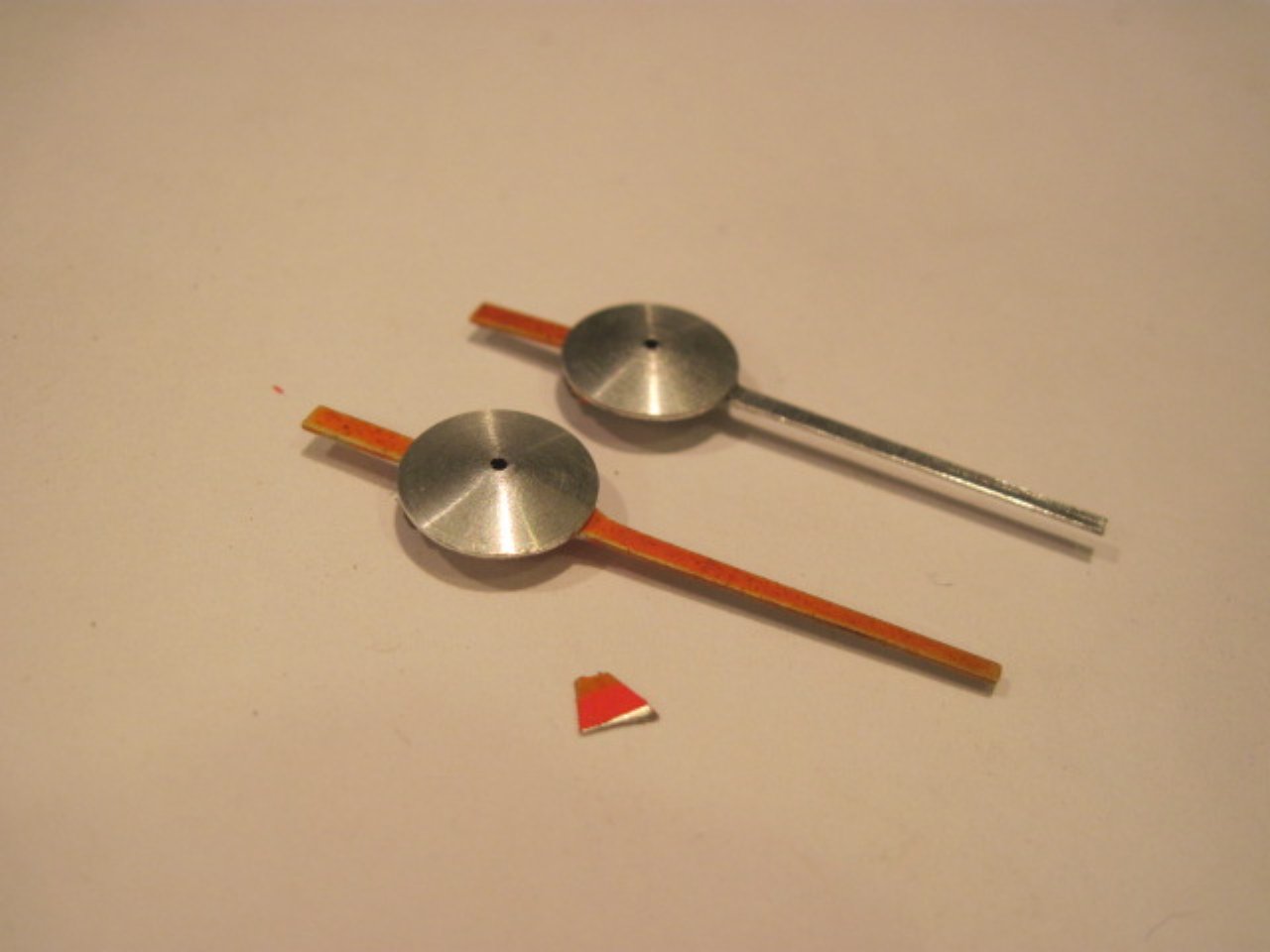
New fluorescent orange paint:
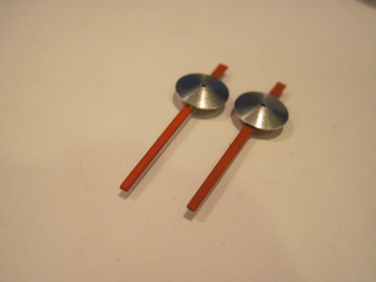
Put the faces and pointers back on , and now it's time to calibrate.
I built a jig to hold the instrument, a variable speed drive motor, and an optical tachometer. The
stand is from a little Dremel drill press. At first I tried to use
the Dremel tool as a motor to spin the instruments, but after I got
everything made and set up, I found the Dremel turns counterclockwise.
I took it apart to see if I could remedy that. It
was a permanent magnet motor, and while they are easy to reverse in
principle, this one was so tight inside, there wasn't a good way to do
it. Next try was a Craftsman chainsaw sharpener. It
too ran counterclockwise, but was a series wound universal motor, so
all I had to do was reverse the brush wires. The shaft from
the motor to the instrument is 1/8" key stock turned to 1/8" round to
fit the motor's collet. I ended up cutting the shaft in half
and joining it with a piece of rubber tubing to accommodate a little
misalignment better. I used an electronic motor speed
control to vary the speed.
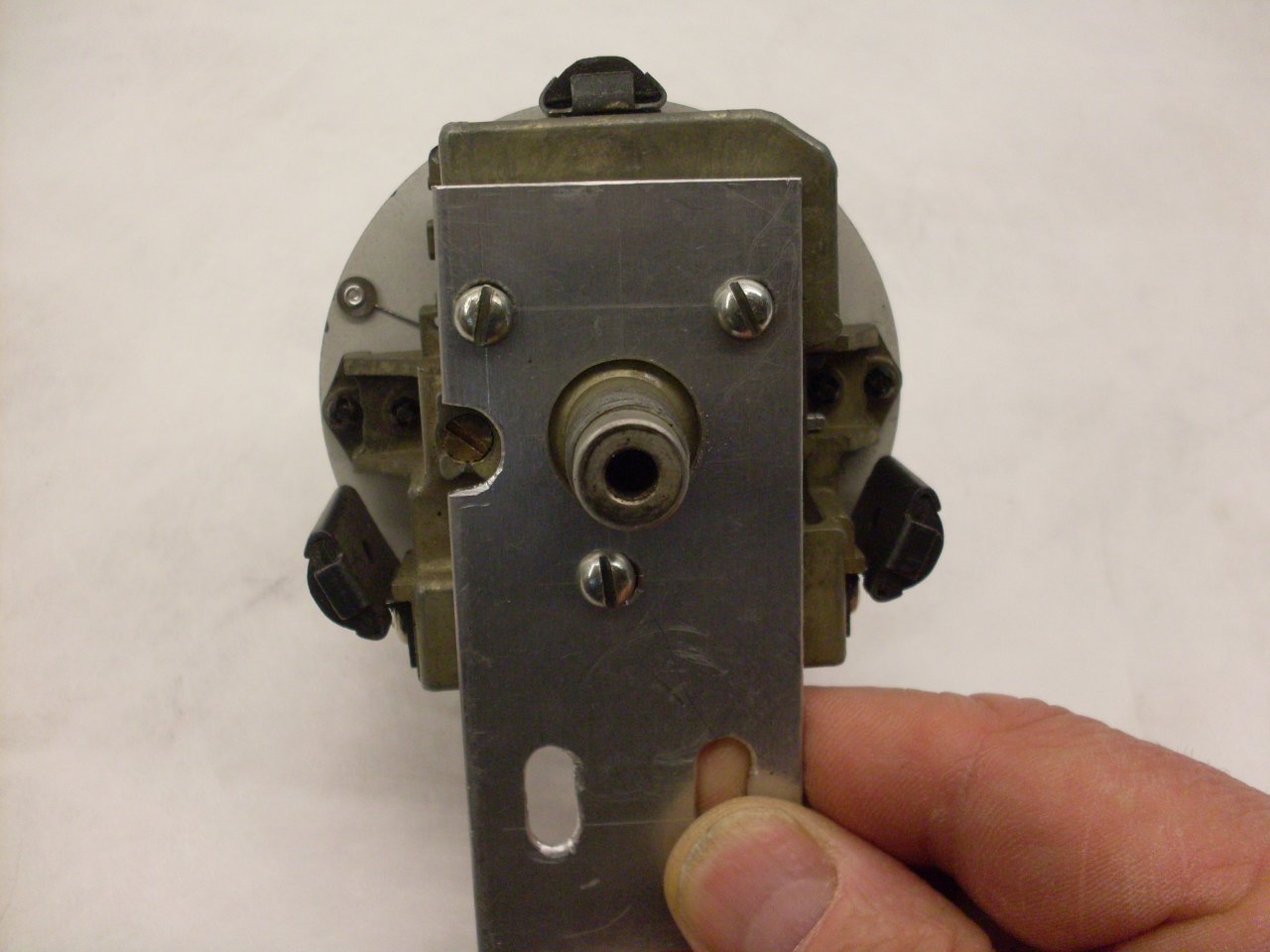
First picture shows the adaptor to mount the instrument on using the
three threaded holes in the back ofthe casting. What looks
like maybe 8-32 threads are really 4BA, which is 0.142 x 38.5 tpi. The calibration screw is also visible.
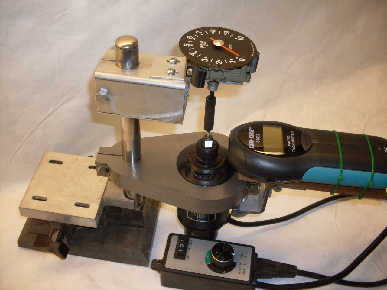
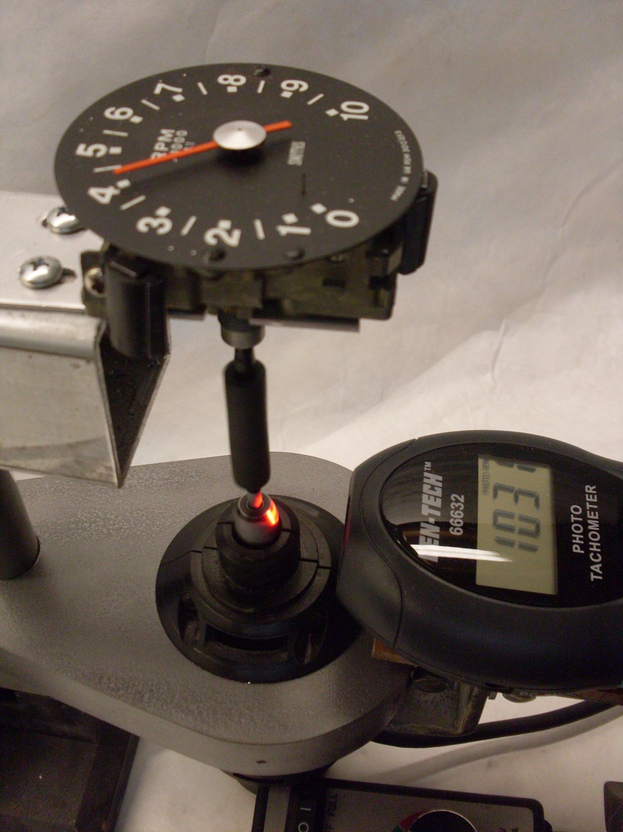
The tach is a 4:1 instrument (as indicated on the face shown in the
second picture at top), so 1000 rpm on the input shaft should
read 4000 rpm on the tach dial. Turning the calibration screw
on the back of the unit moves the modulation plate, varying the magnetic
field the aluminum disk sees. Smiths speedometers like this have
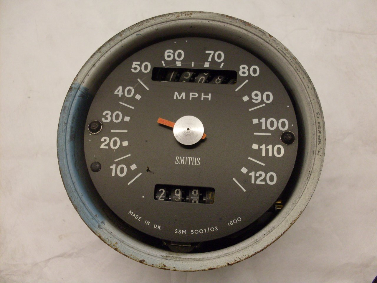
a marking on the bottom of the face that indicates the number of
revolutions of the cable that will rack up one mile on the odometer.
On mine, it was 1600 (see very first picture above). This
implies that 1600 rpm on the input cable should indicate 60 mph (one
mile per minute). Both instruments calibrated fine, and appeared
to be working well.
So
with the guts in servicable order, I turned to the "cans", or shells
that the instruments mount in. They were in good shape, but the
paint and the rubber parts had seen better days.
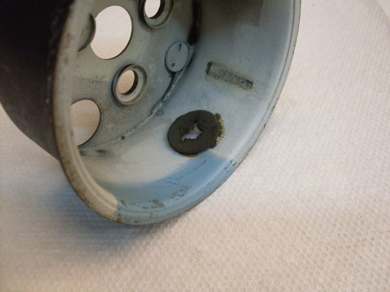

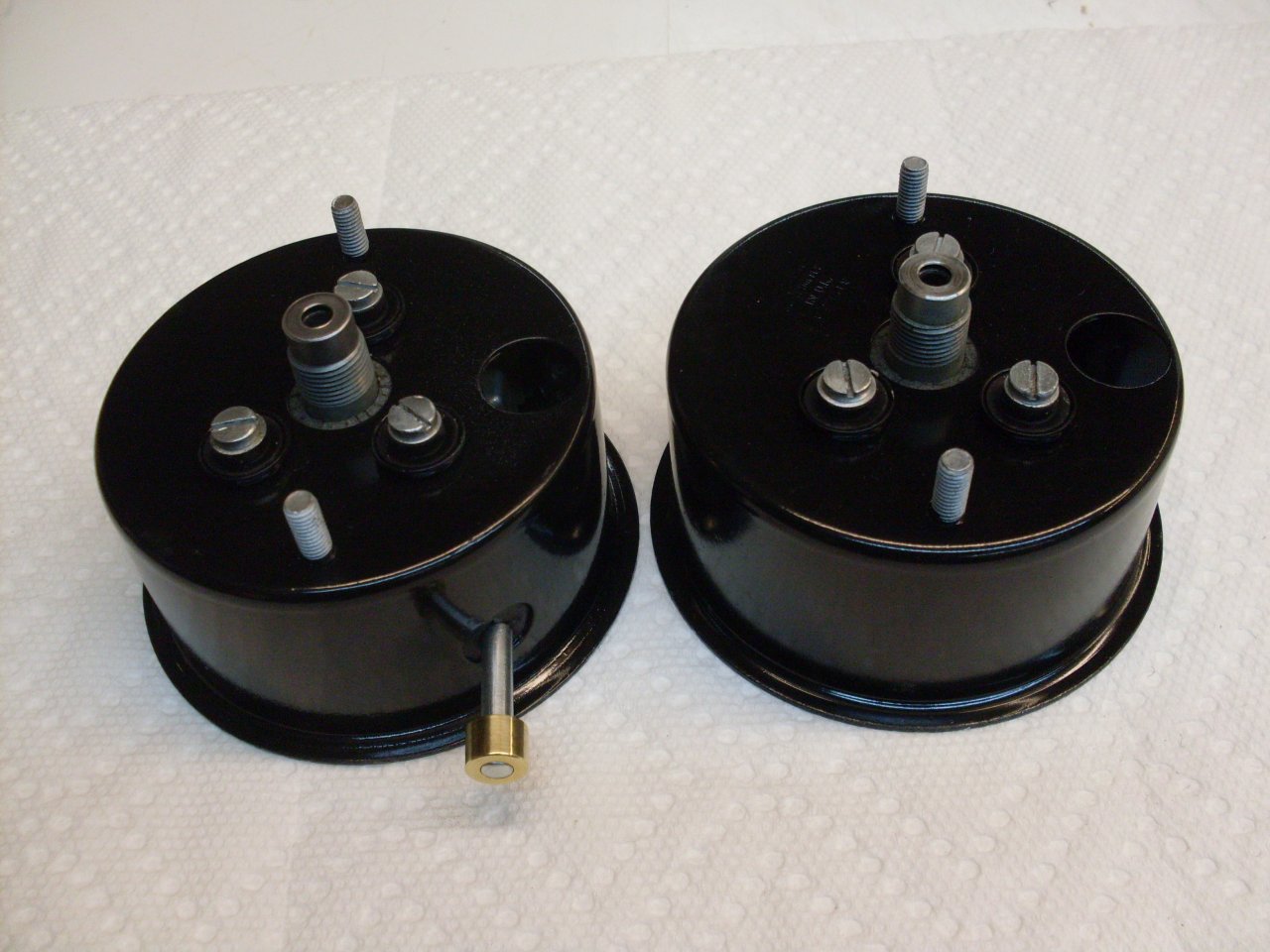
The
cans cleaned up well with a little blasting and paint. The inside
is painted white so that more of the light from the internal instrument
light makes it to the dial face. There was a greyish area painted
on the originals, which I assume is to mute the light right above the
lamp, so as to even out the light on the face. It hadn't been
applied yet in these pics.
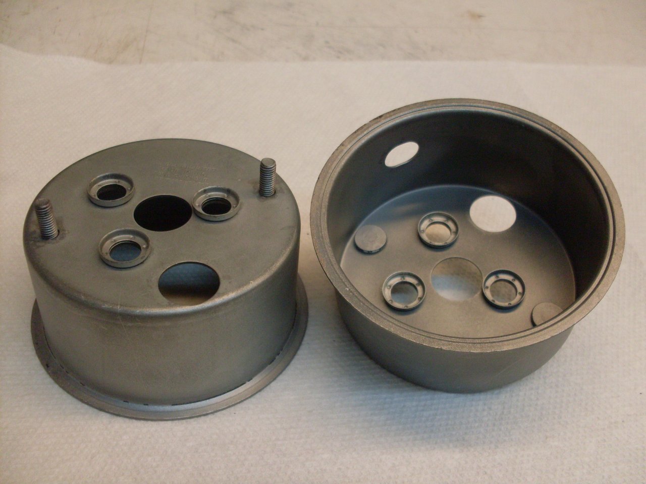
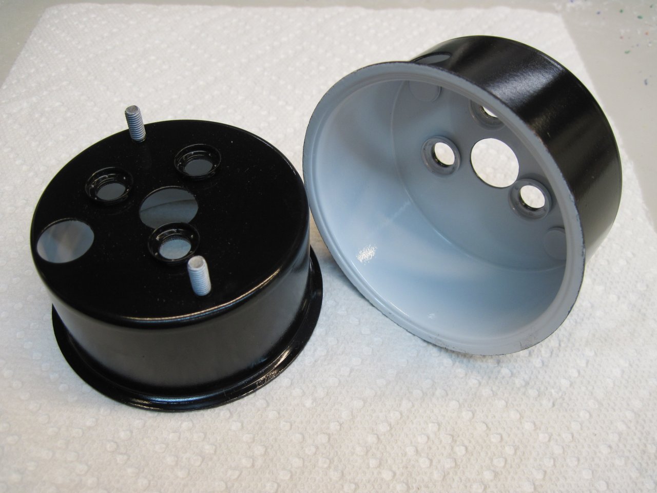
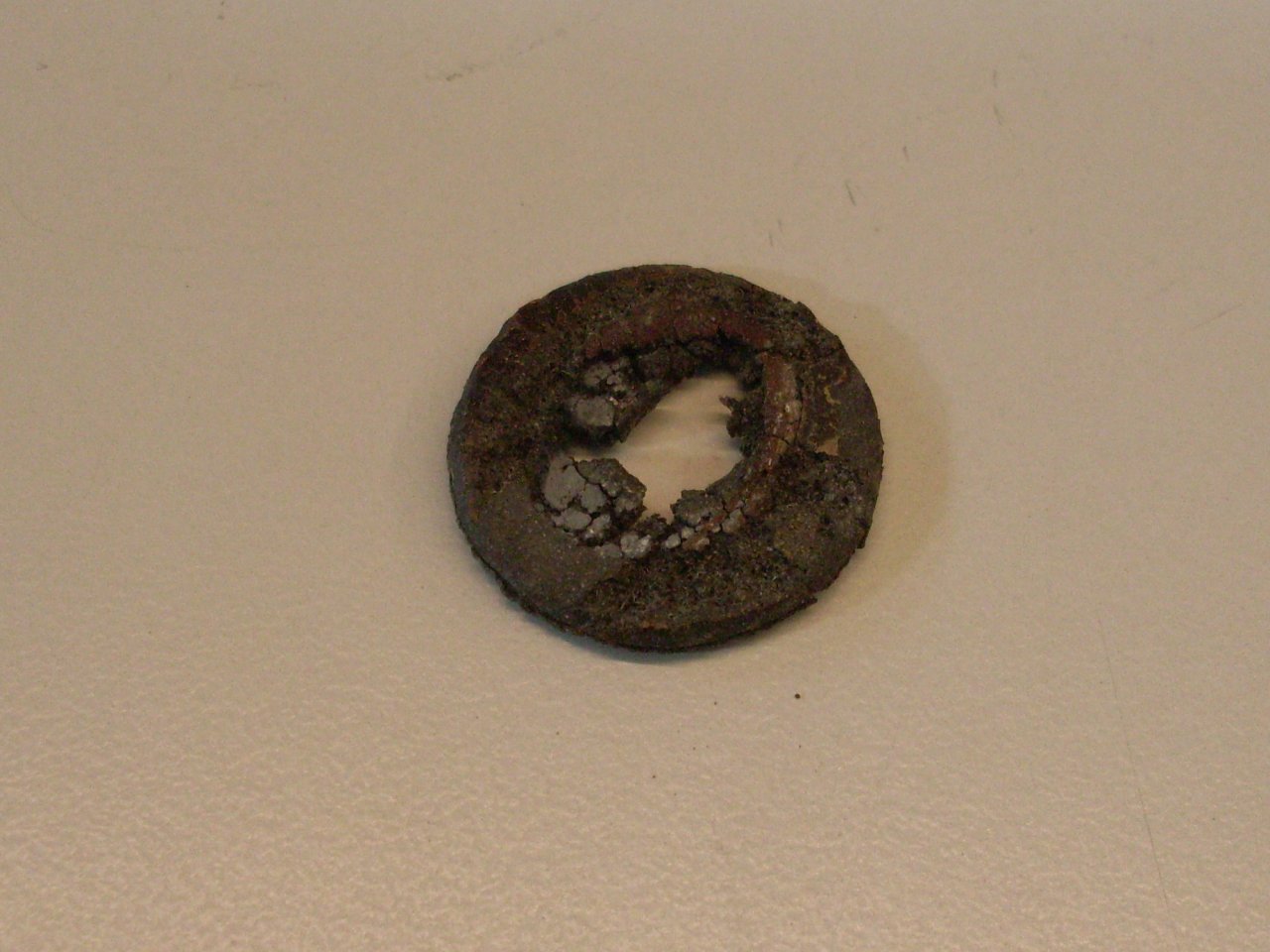
The
rubber parts weren't so easy. There are six grommets in
each instrument that serve to isolate the internal mechanism from
vibration or shock. These were all badly distorted and
deteriorated. There was also a rubber disk with a slit to
seal around the trip odometer reset shaft.
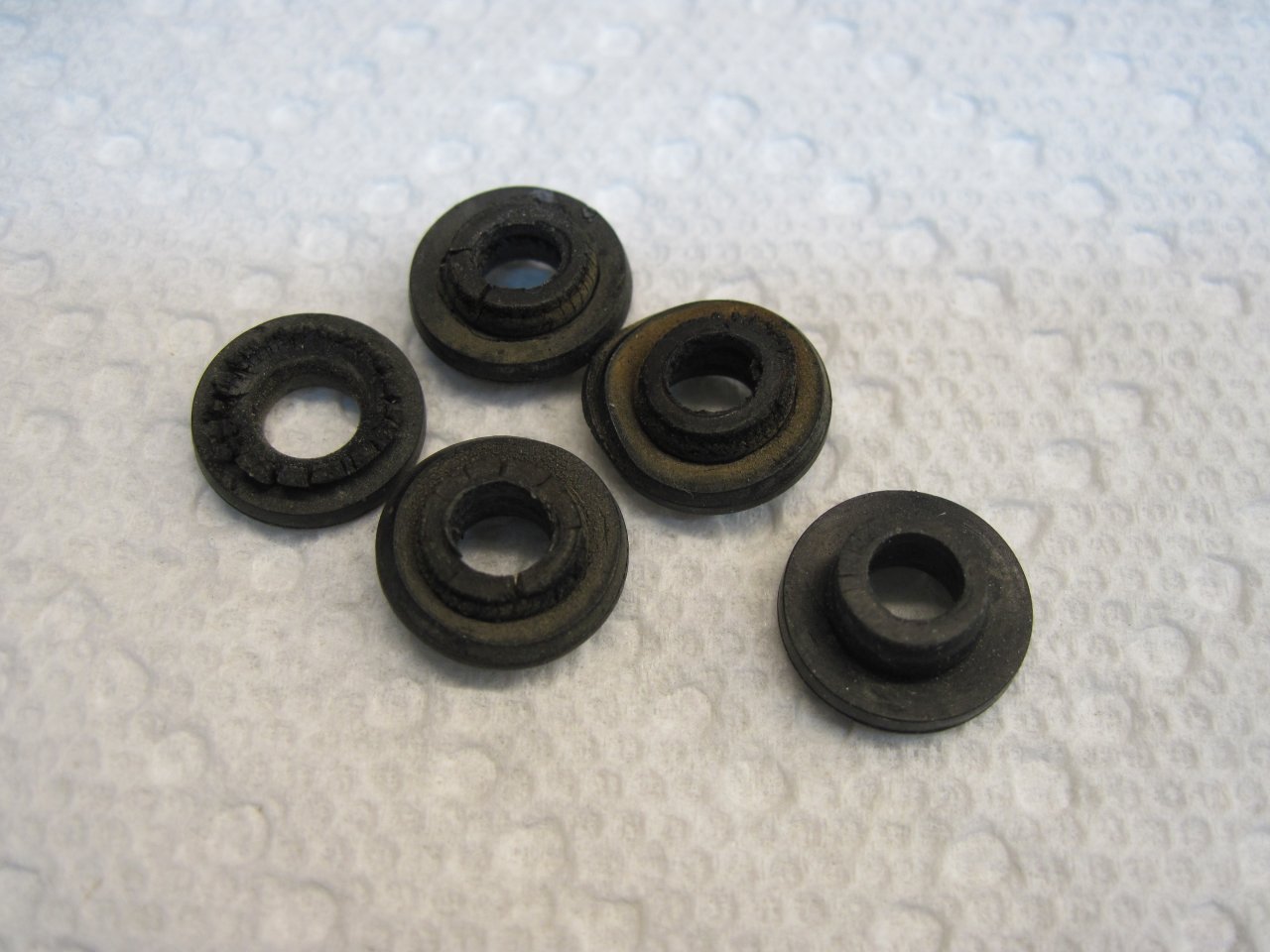
I found a place claiming to sell grommet/hardware kits, but they didn't
really have them available. The fallback position was to make new
ones, but since that process was fairly involved and not pertinent to
this story, I'll skip over it here. If anyone is really interested, follow this link.
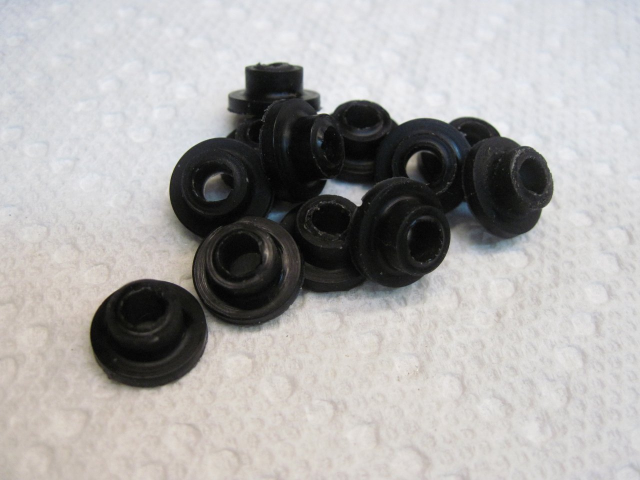
Here are the new grommets, and a new little gasket for the trip
odometer reset tool. It was punched out of some rubber sheet with
that one-use punch made from a piece of sharpened electrical conduit:

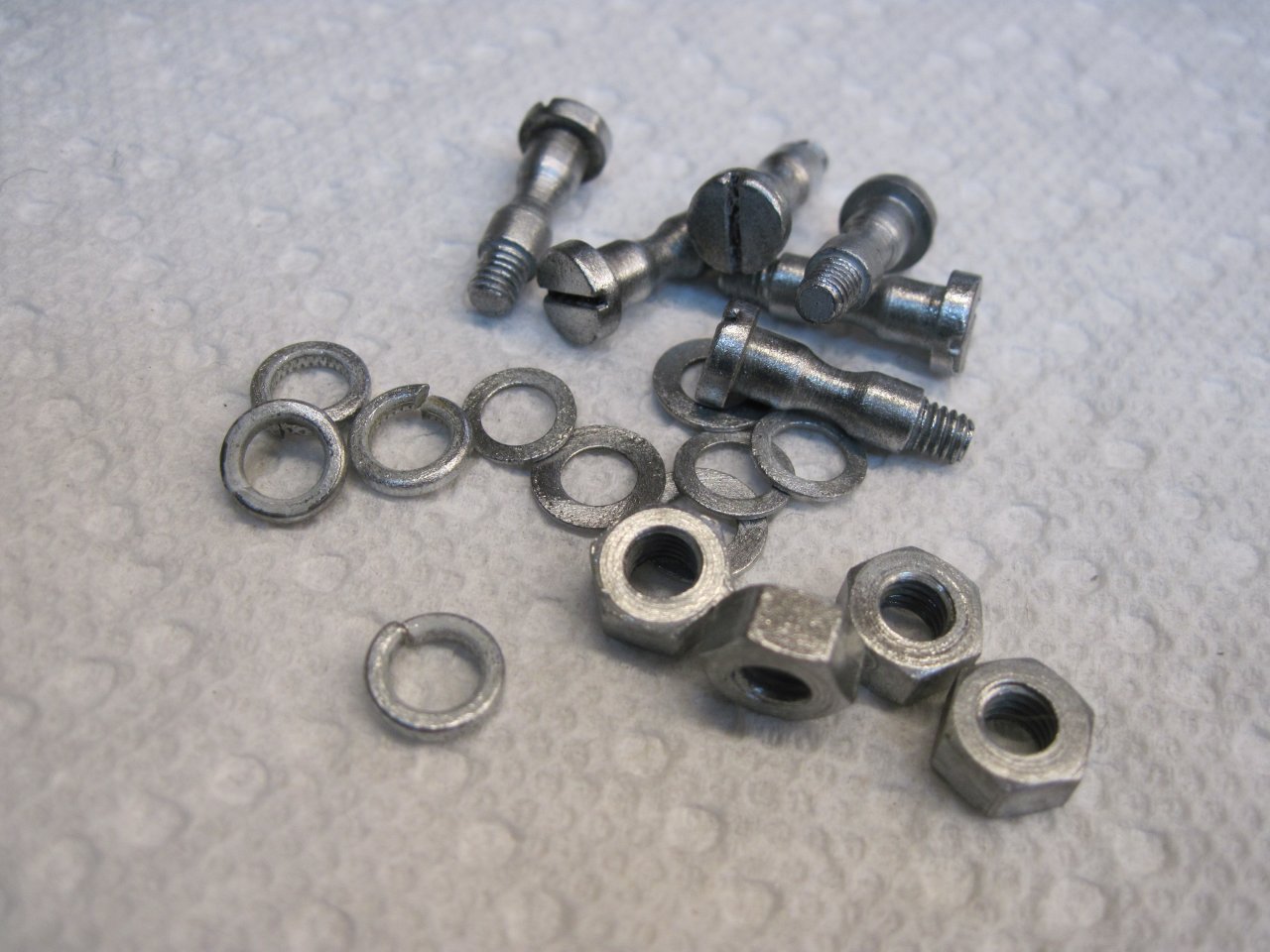
The
replated the special mounting hardware. Those screws are 4BA
threads. Not much chance of finding those at Home Depot.
Everything ready to go together.
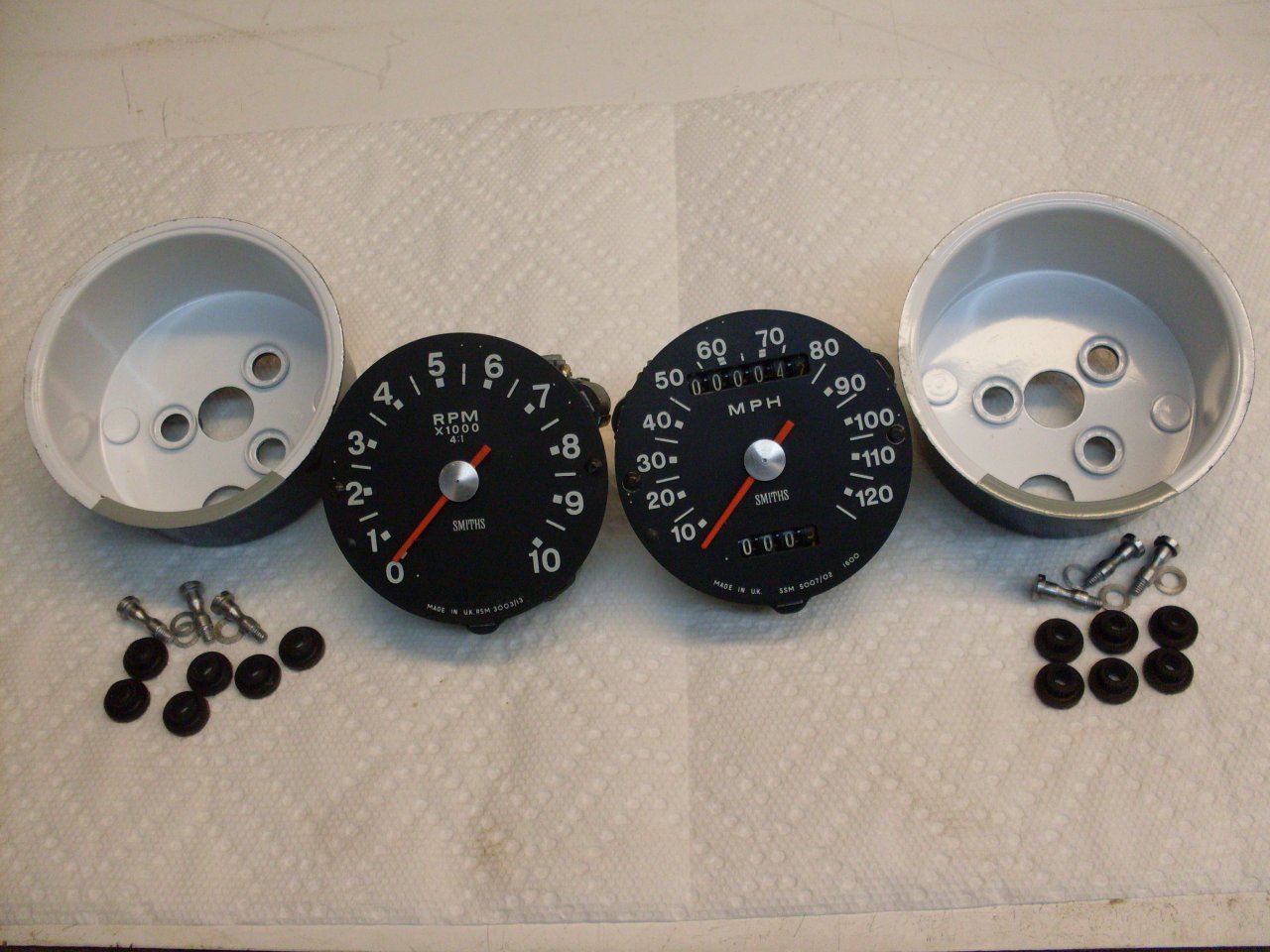
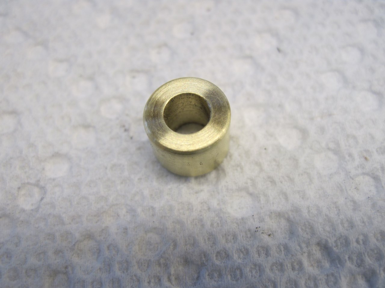
There is also a little foam cushion that goes in the bottom of the can.
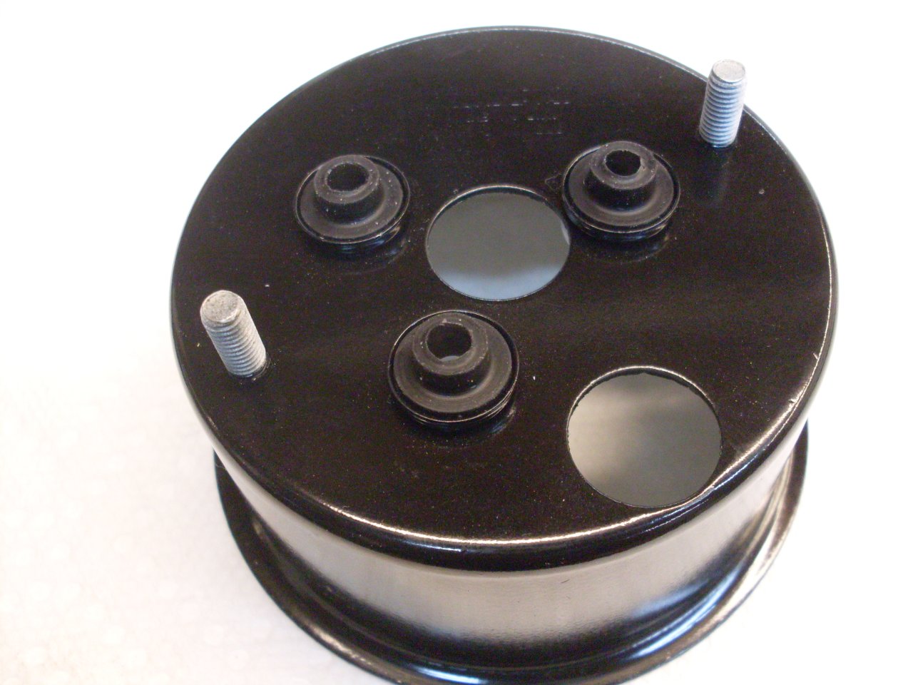
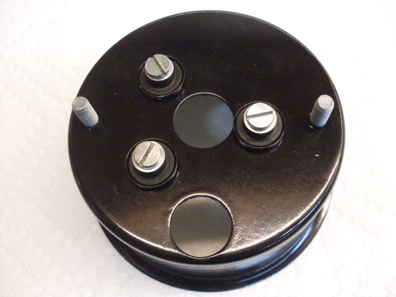
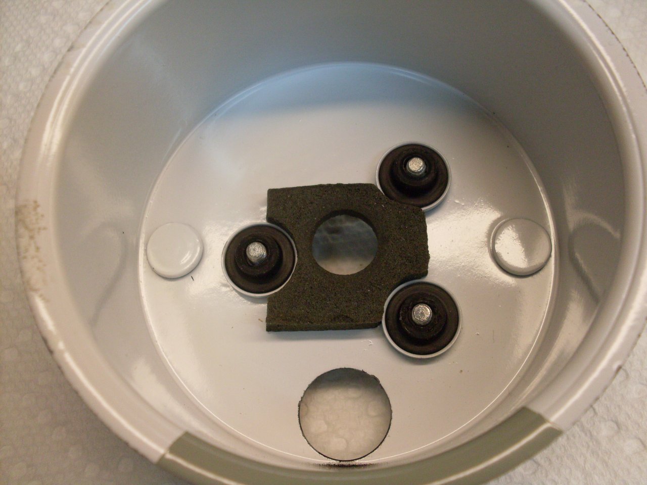
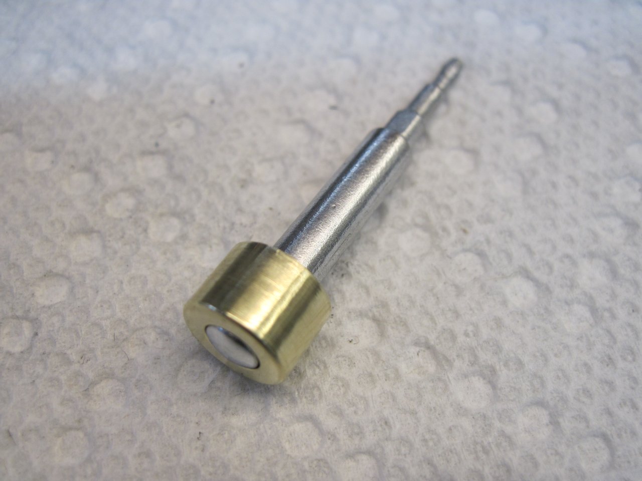
Made the trip odometer reset tool, since mine was long gone. Blighe's book shows a dimensioned drawing of the tool.
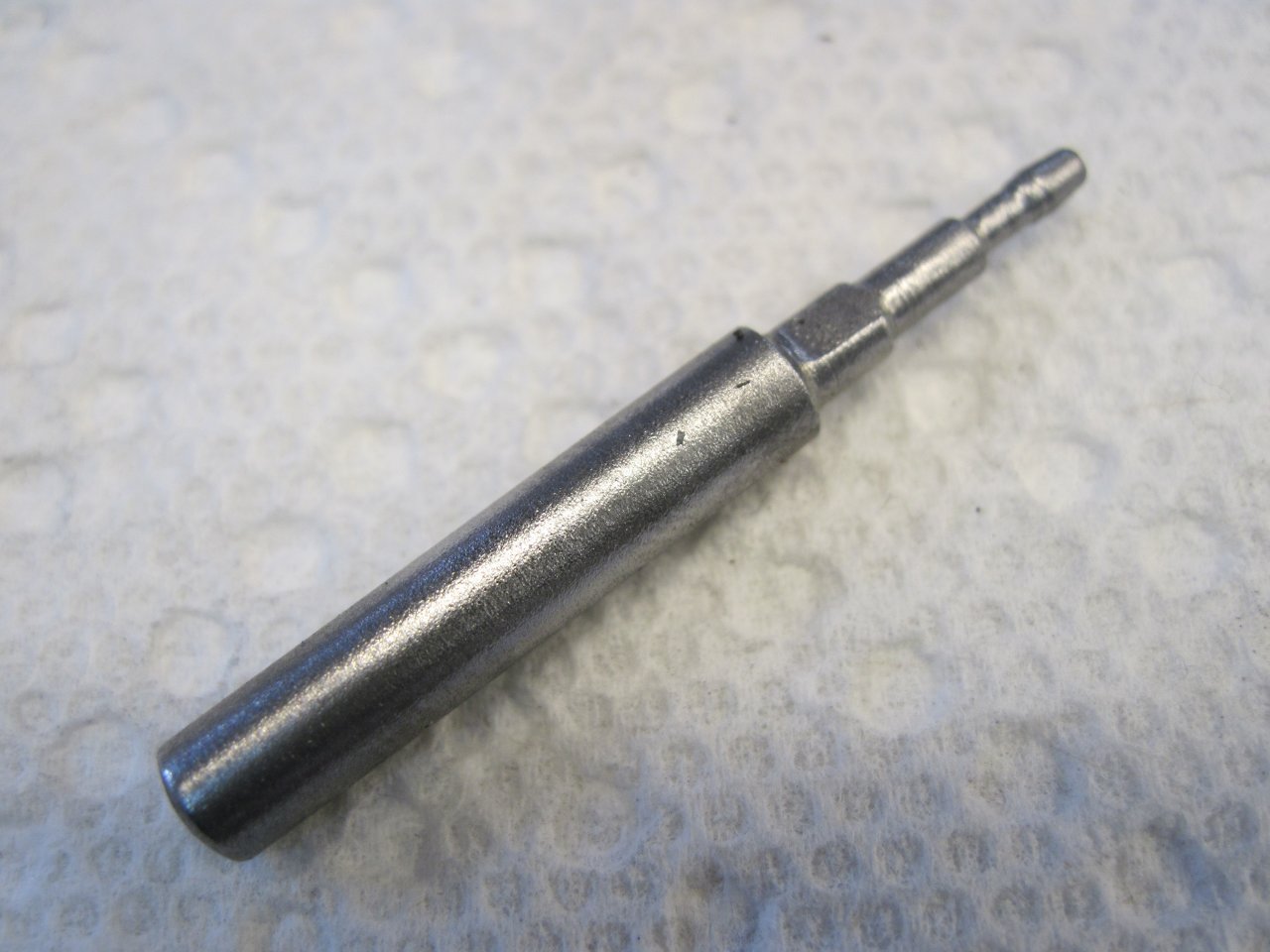
Ready for bezels:

Bezel
kits are available, and I ordered a couple. As anyone who fusses
with old cars or bikes knows, reproduction parts are always a bit of a
crap shoot. The first bezels I got for a good price were slightly too
small, and would have required grinding a bit off the flanges of the
instrument cases. I might have done that, but I also thought the
quality of the rubber gaskets was shoddy. The next sets I got
from a different supplier were much better. Even with the second
pair of kits, one of them had a very visible scratch in the glass.
My 40-year old original glass was better, so I re-used it.
The
bezels must be crimped onto the instrument cases sufficiently tight to
compress the rubber gaskets enough for a water seal. There are
sources, including Blighe's book that suggest that the crimping
can be done using simple hand tools. I was skeptical that a
reliable seal could be guaranteed this way, so I did a little more
research.
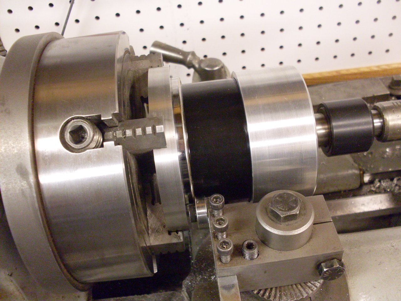
One very nice blog showed a picture of the "Smiths factory tool" for rolling the crimp:
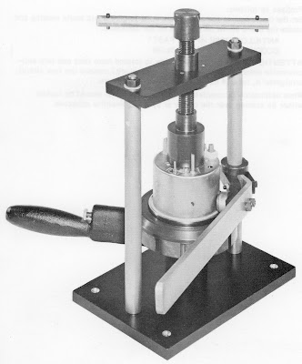
I considered building the tool,
but the blog also describes a method using a lathe to press and turn
the instrument while the crimp is rolled. I have a small lathe,
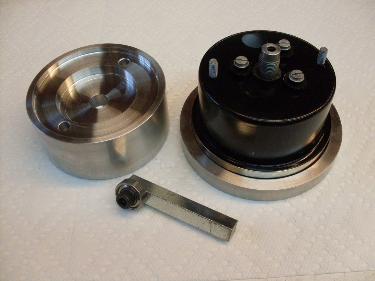
so this seemed to be the better approach. First, simple adaptors
must be made to fit the front and back of the instrument to hold it in
the lathe.
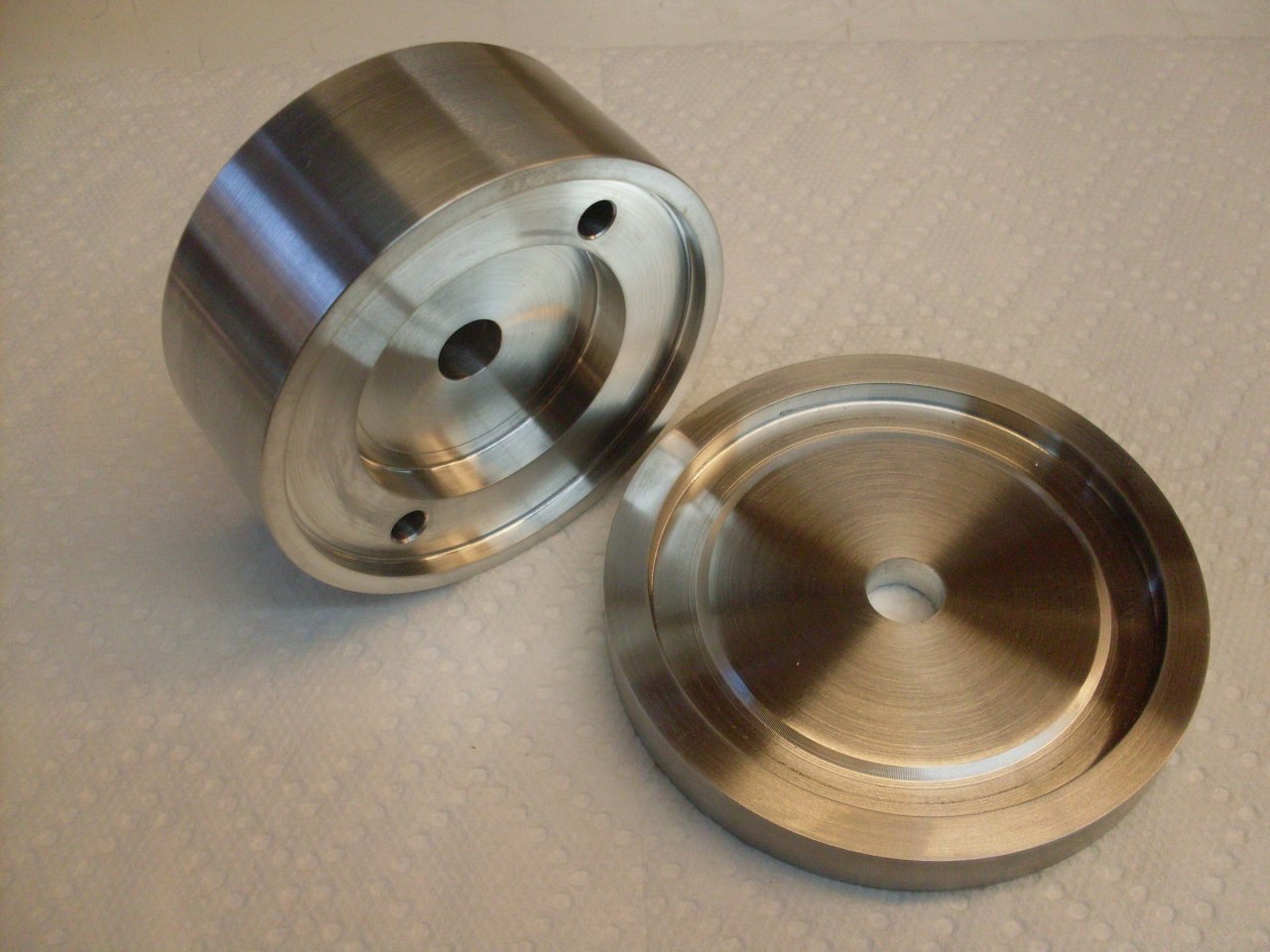
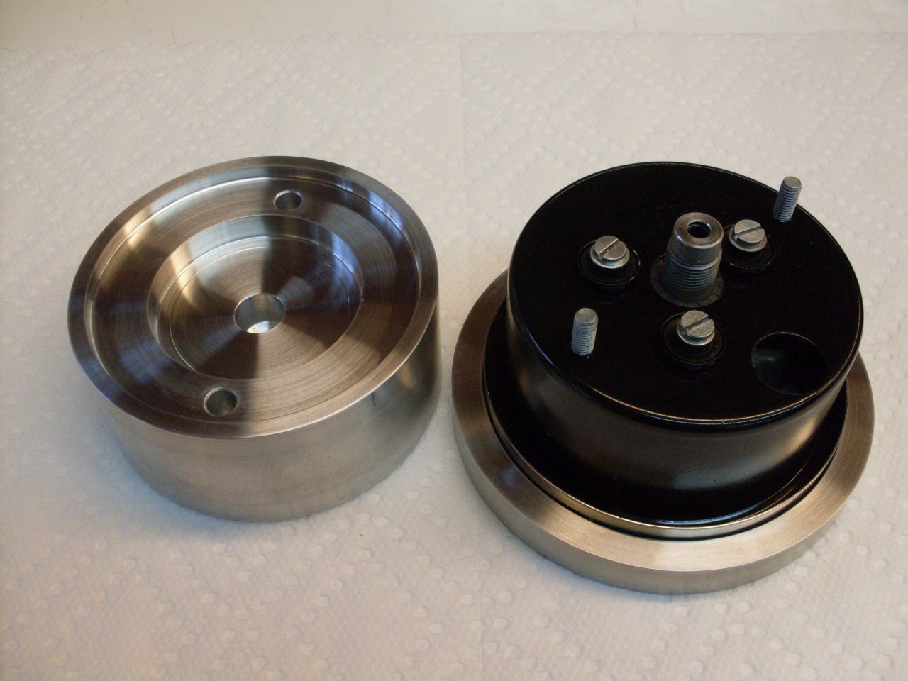
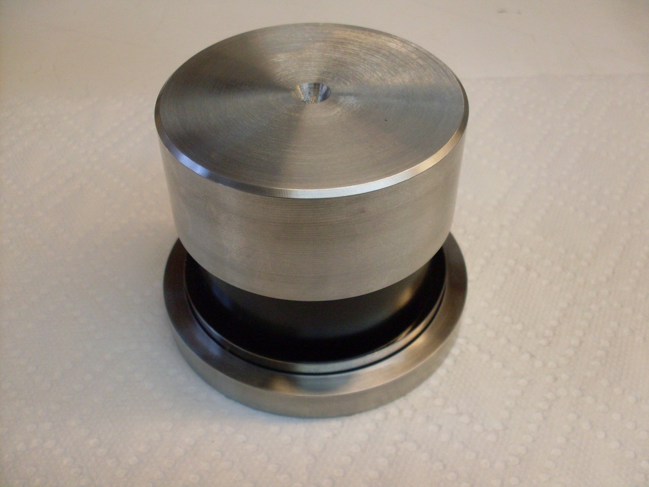
Also
a ball bearing is fitted to a piece of key stock that is held by the
lathe's tool post. The bearing is what rolls the crimp.
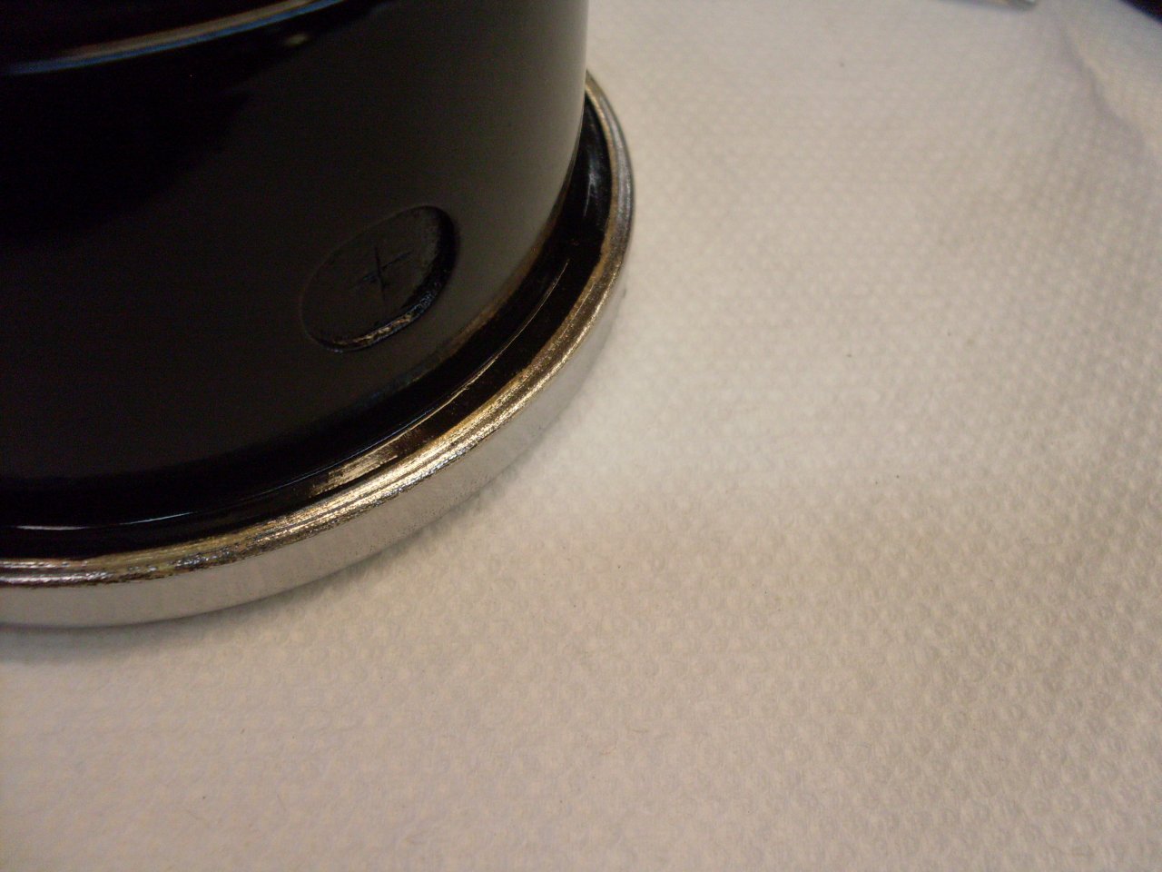
I didn't use power in the lathe--just turned the chuck by hand as the tool was slowly advanced. The
crimping operation flakes some of the chrome plating off the brass
bezel where the tool rubs on it. Not sure how to fix that, but it
is pretty much out of sight anyway.
The
finished speedometer. On the tachometer, which I did first, I put
a thin smear of RTV on the gasket between the case and the glass
to ensure water tightness. This was a bad idea, since the
RTV made the gasket slippery enough to extrude out of place when the
compression pressure was applied. Of course this couldn't be seen until
the crimped instrument was taken out of the lathe. I had to
remove the bezel, and order another one.

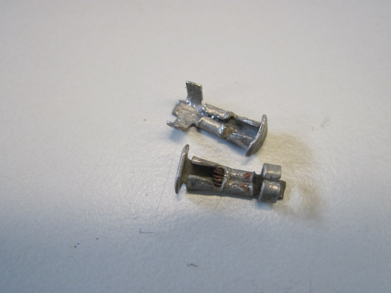
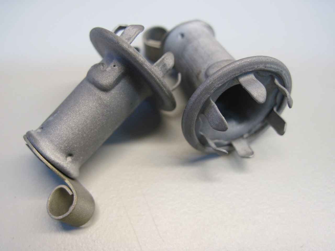
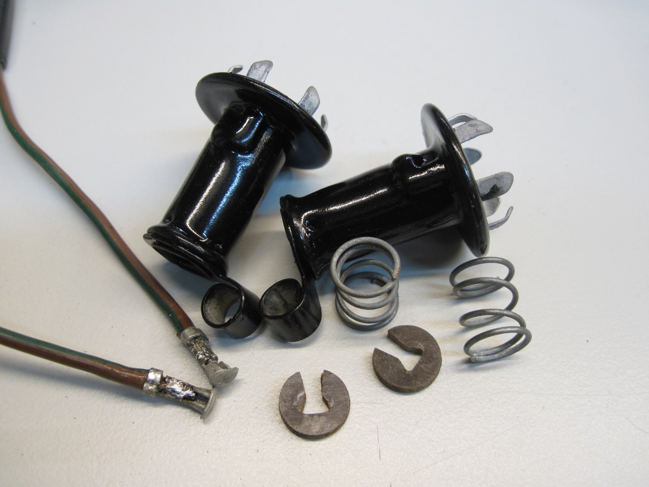
The
instrument lights are pretty crude little lamp holders that snap into
the back of the instrument cans. They were grungy, and one of the
hot wires had broken off the internal lamp contact, but they were
otherwise undamaged. These aren't really designed to be repaired,
and replacements aren't all that expensive. On the other hand, it
appeared that I could bring these back to life with an hour or two of
attention, and I'd save 20 dollars. Besides, judging from
experience, the replacements would likely be of lower quality than the originals.
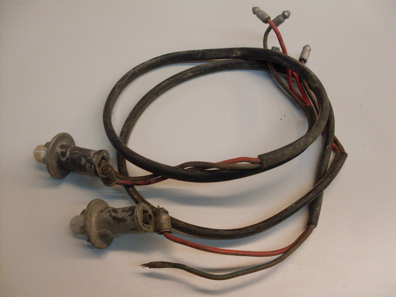

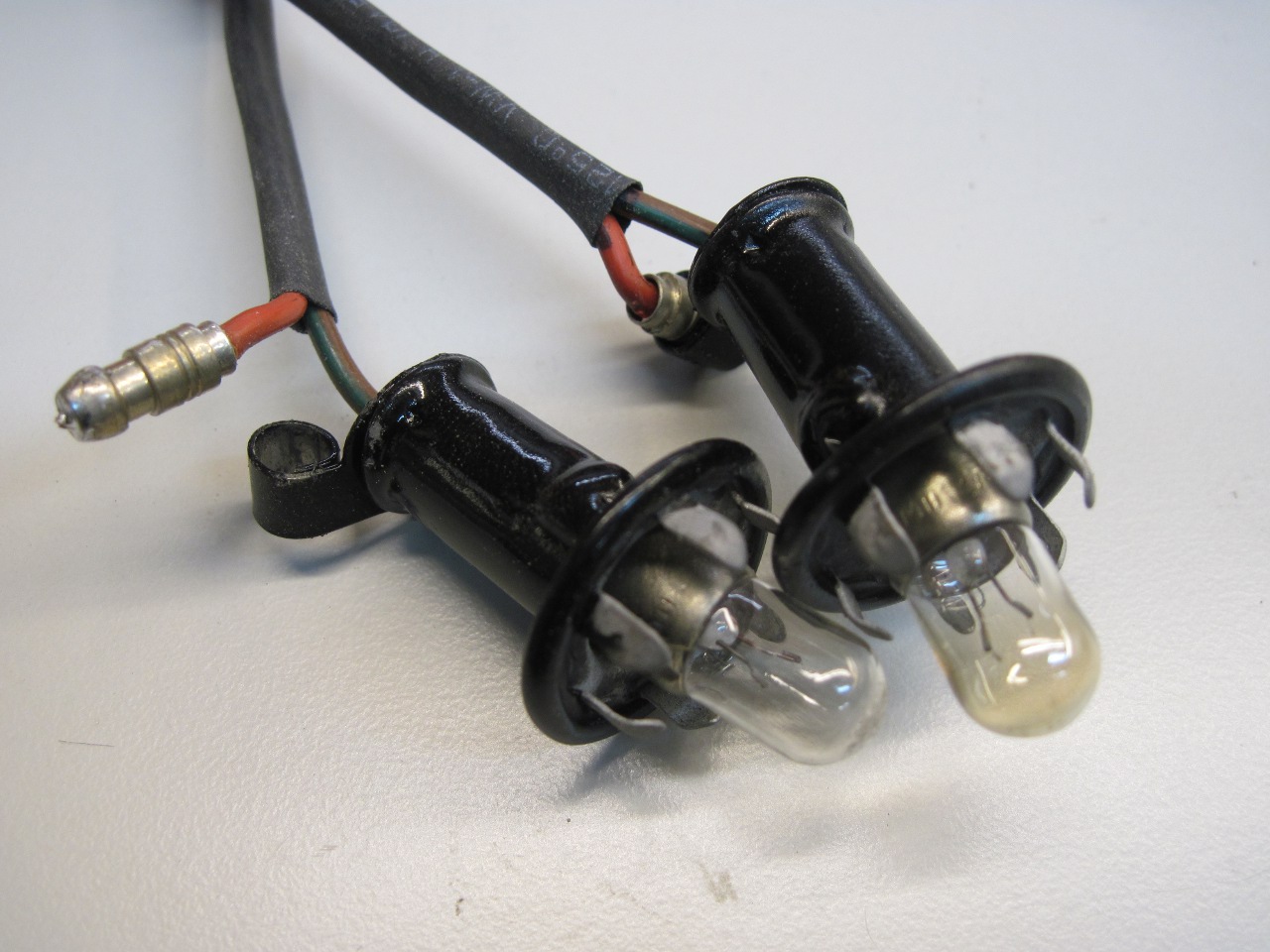
The
most challenging part was to pry open the tiny hot contacts so I could
re-crimp and solder the wires to them. Then I balsted and painted
the holders and put them all back together. I put real solder-on
bullets on the ground wires instead of those tacky little quasi bullets
that the bare wire just wraps around. Also extended the heat
shrink up farther toward the instrument.
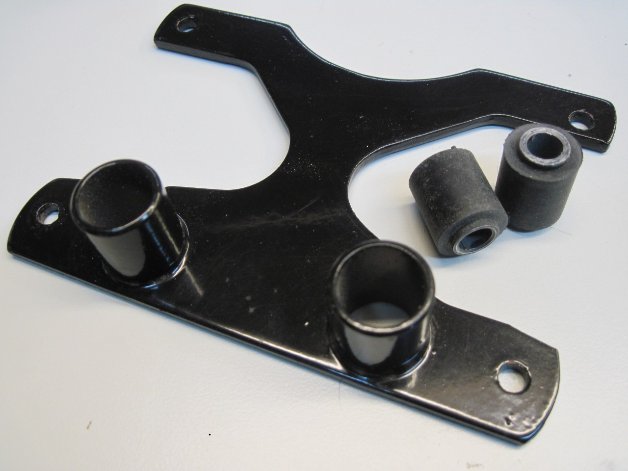
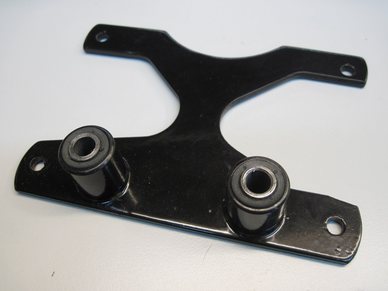
The
instrument mounting bracket is fastened to the steering top lug with
two resilient "Metalastic" rubber bushes to isolate vibration.
The bushes are pressed into housings on the bracket. They
have to go in far enough so that when mounted, the bracket is held away
from the top lug.
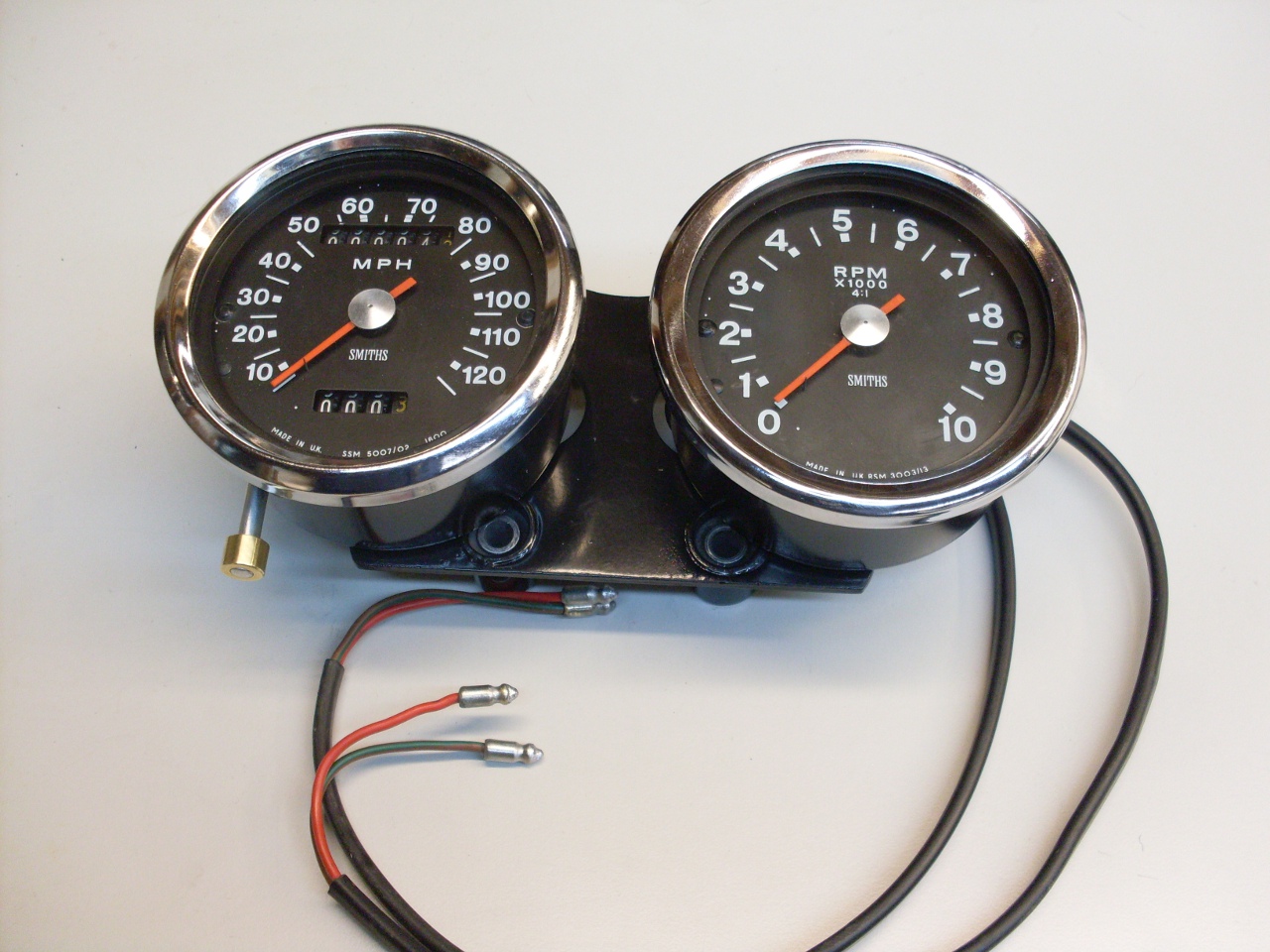
The finished instrument cluster:
To Other Pages
Send comments to: elhollin1@yahoo.com

