To my other TR6 pages
November 12, 2017
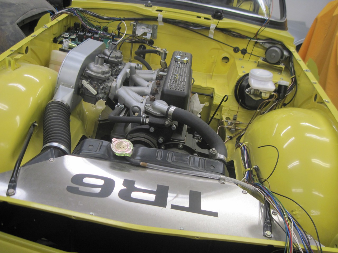
Wiring
[Click the pics for a bigger view]
Many
people, including me, consider the electrics to be one of the weakest areas on a TR6.
It is rare for a TR6 to attain much age without at least some
electrical trouble somewhere. Cheaply made switches, bad ground
connections, marginal wire sizes, and an absolute minimum of fuses and relays make the
system sort of failure prone.
This has led to a good niche market for
upgraded wiring arrangements which offer expanded use of relays
and fuses. This approach can reduce the current load on wiring
and switches, which should improve their longevity and reliability.
The commercial products available are well spoken of.
On
the other hand, as a matter of education and experience, the the
electrical system is probably the part of this car that I understand
the best, so it seemed logical and reasonable to consider
designing an
electrical system from scratch. The system would incorporate
some of the "modernizations" I've added, like the pre-wired dash, new
console switches, re-located ignition switch, auxilliary power outlets,
seat heaters and electric radiator fan. It would also make it one
of the
most extreme departures on this car from stock, and abject blasphemy in
many folk's eyes.
I started with a few points of philosophy for the design:
1. As far as possible, OEM type switches and indicators will be used.
2.
All loads of 5 amps or greater will be contolled by a
relay. [This implies that no dash switches will see more than 5
amps. There are 7 relays in the PM (plus a spare).]
3. As far as possible, each load or group of associated loads will be on a separate fused circuit. [I ended up with 22 fused circuits including 3 for expansion.]
4. As far as possible, no load will use the body of the car for a return path. [The only items still without an explicit return wire are the temp sensor, starter, and distributor.]
5.
As far as possible, OEM wiring color assignments will be
followed. For new circuits, wire colors will be compliant with
BS-AU7 Vehicle Wiring Color Code.
6.
Wire will be sized according to the maximum current it would
carry in any normal scenario, plus at least 10% margin above the margin
built into the wire ampacity. [In some cases, this meant upsizing from stock wire.]
7. Fuses and relays will be easily accessible.
8. The system will include simple visual diagnostics.
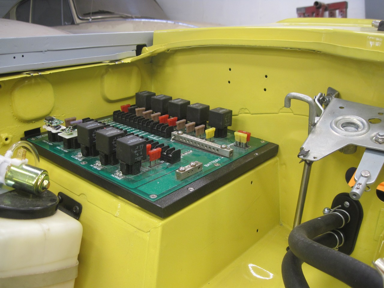
The design I came up with included a "Power Module"
(PM) as the heart of the system. It contains all of the fuses,
power relays, and flashers for the system. It also includes a
single point ground bus for return lines from all over the car.
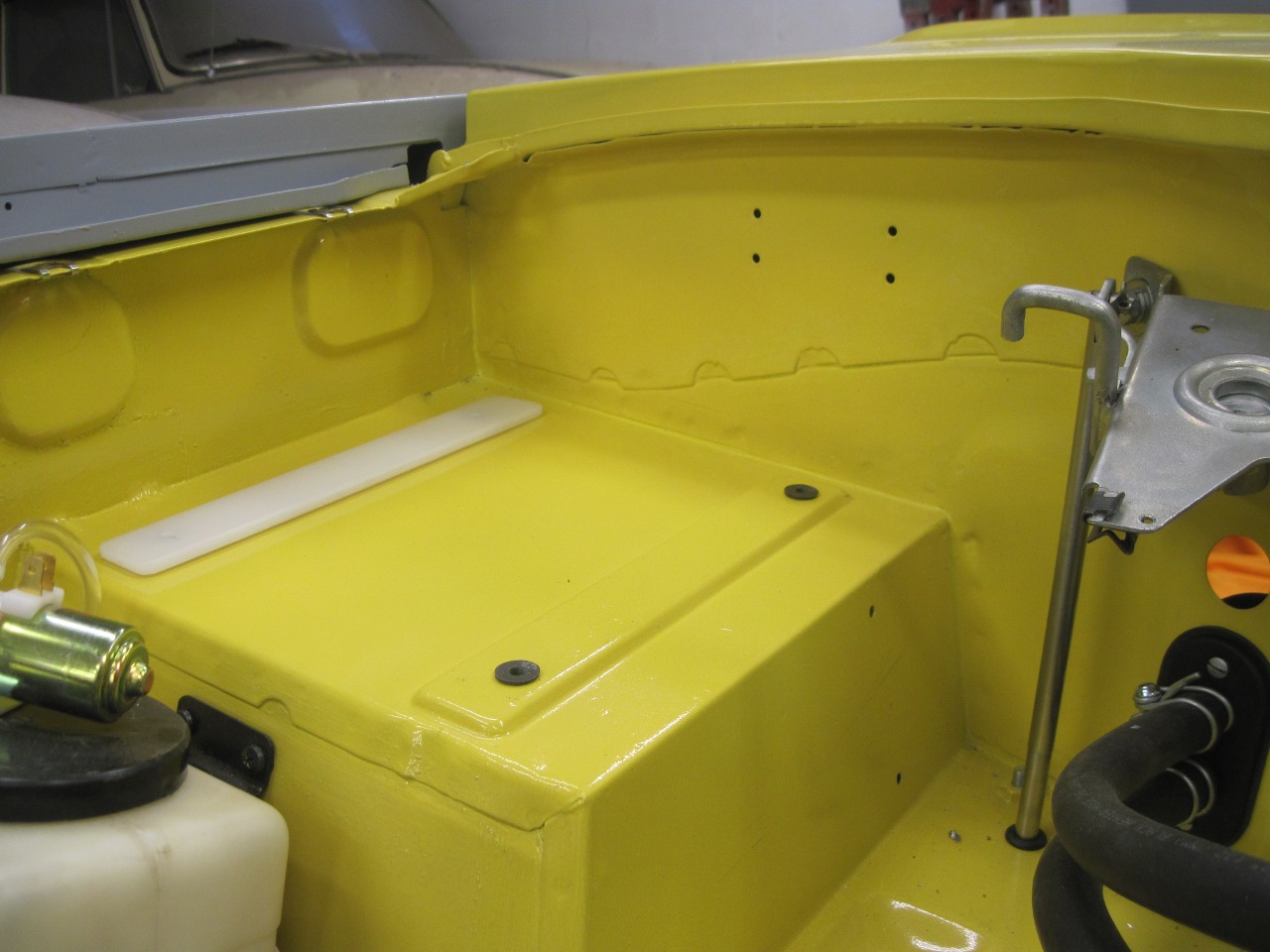
The PM was sized to fit in the engine compartment on the shelf
above the passenger footwell.
To prep the shelf for the PM, I
installed four rubber "well nuts" to give a bit of a resilient
mounting. A plastic spacer was included to match the
stiffening rib on the shelf.

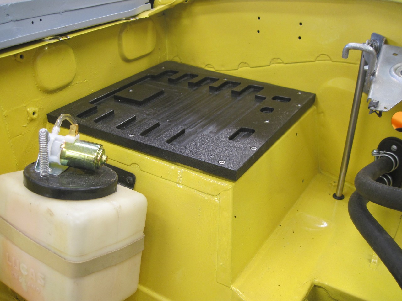
Then on went an HDPE base, milled to clear all the protrusions on the bottom of the PM's circuit board.
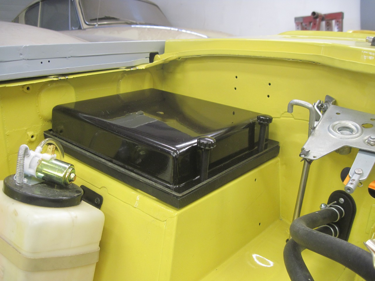
Then a fiberglass cover to try to keep most of the hostile stuff out.
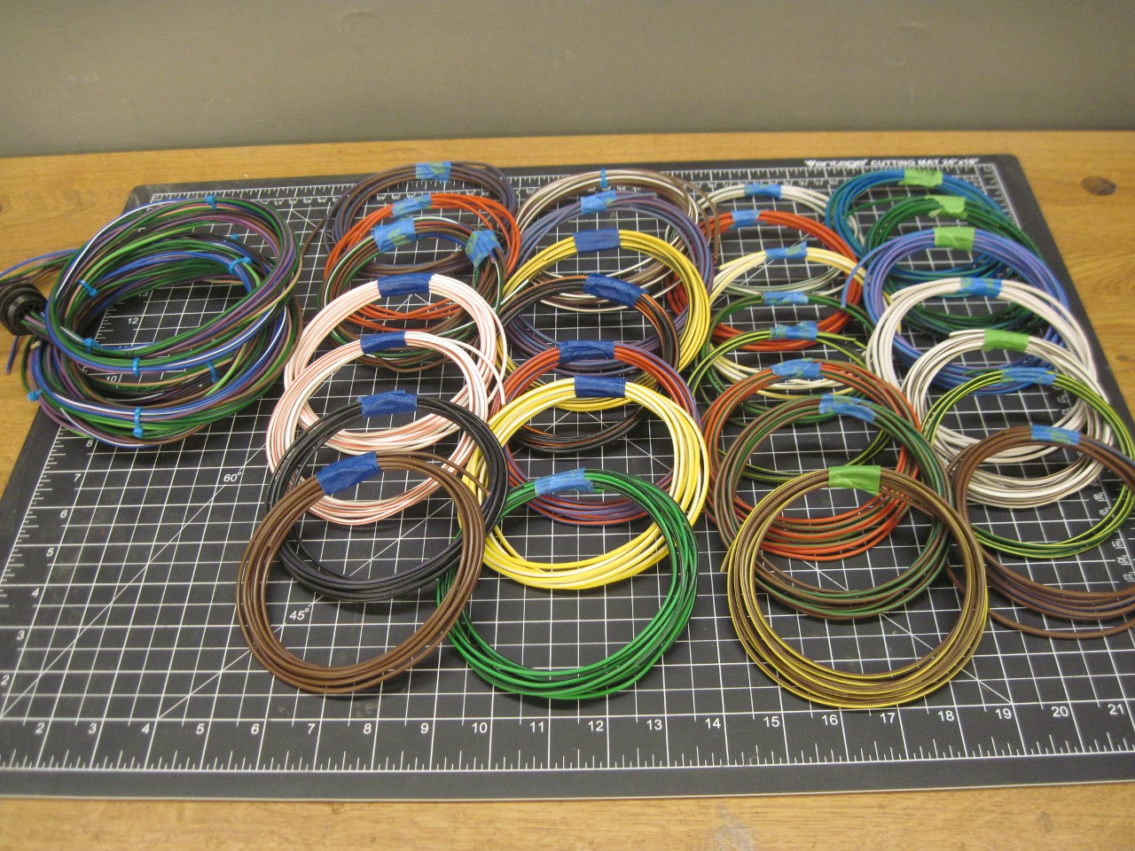
So,
now with the heart installed, most of the rest was just veins and
arteries. I was able to harvest a fair amount of wire from the
original harness, but still had to buy quite a bit of wire in quite a
few color combinations.
There are four main cables in the design:
A cable from the dash to the PM.
A cable from the console (Switch plinth and H frame) to the PM.
A cable from the rear of the car. It drops off a few of its wires at the dash, then goes to the PM.
A
cable from the front of the car, including engine compartment. It
splits near the firewall, with one branch going to the dash, the other
going to the PM.
The
cables connect to the dash and console through in-line multi-pin
circular connectors (three for the dash and one for the console), and
each cable can be removed from the car separately.
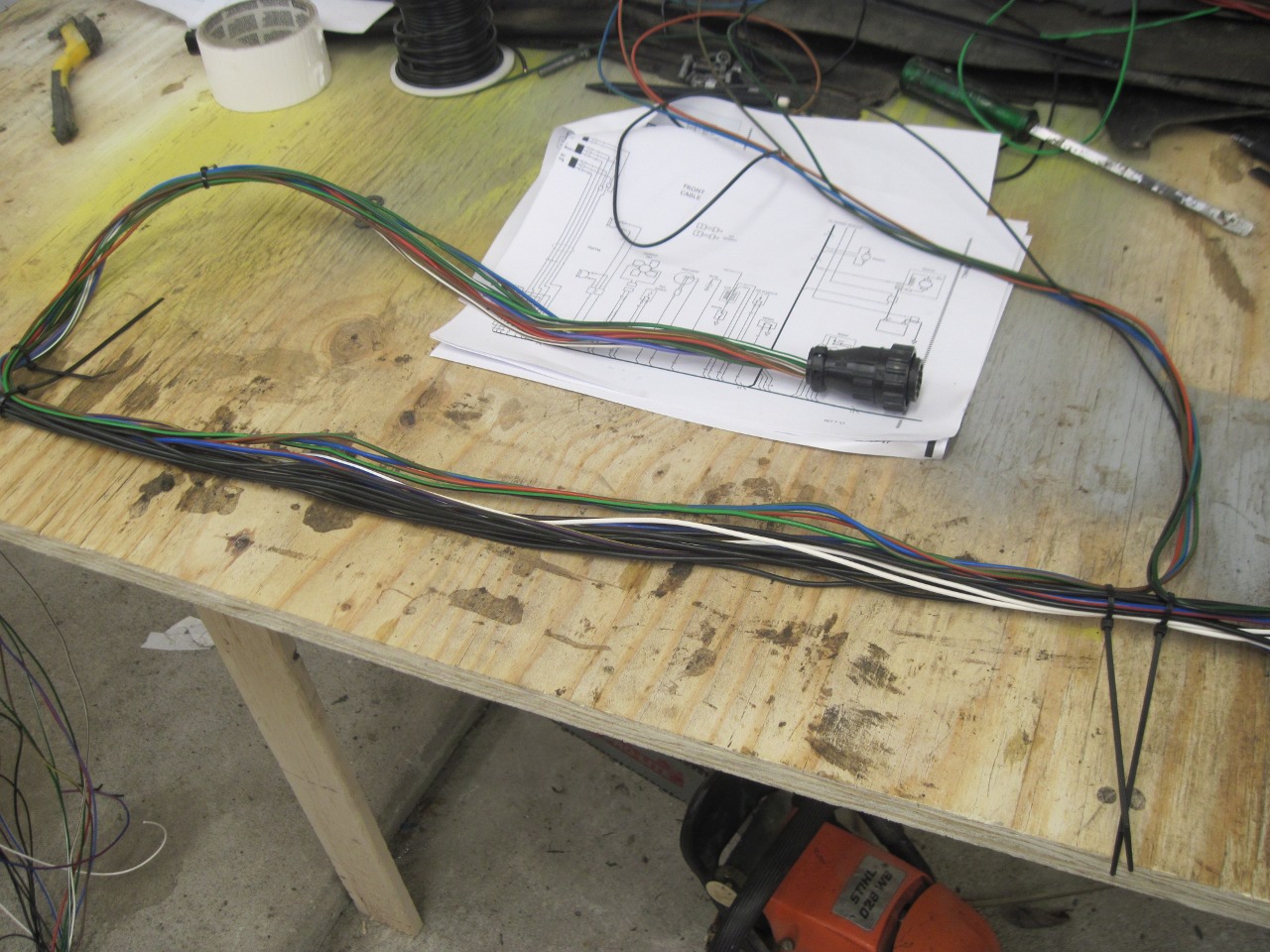
Here is the start of making a couple of the cables.
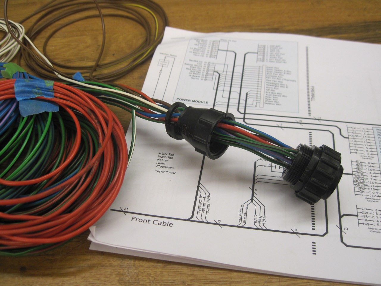
This is the front cable being assembled and routed.
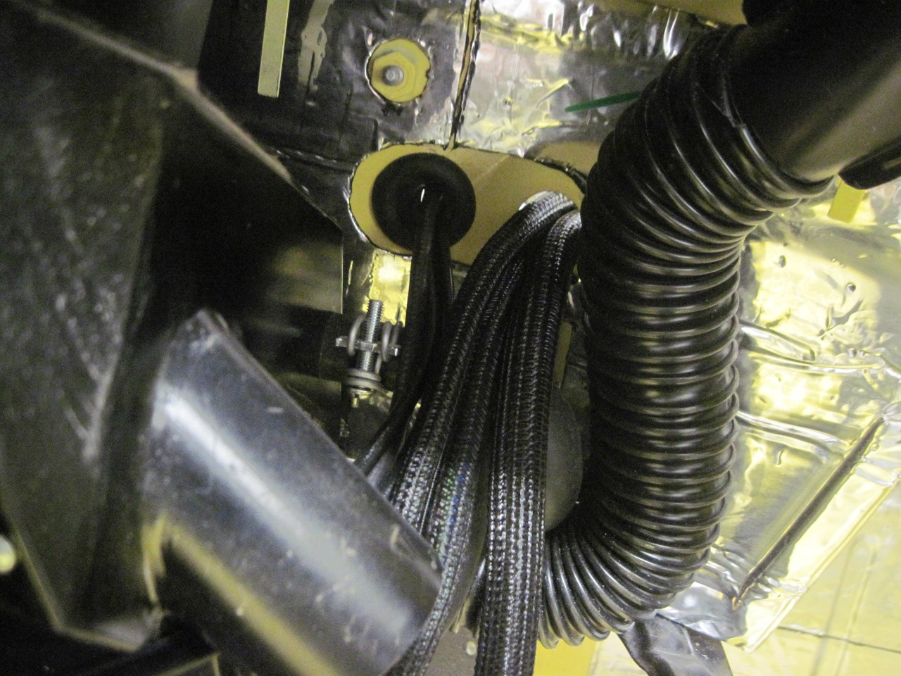
I
used this expandable sheath for most of the cables. It doesn't
bind the wires tightly, so the cable stays really flexible. It
also allows last minute boo-boo fixes.
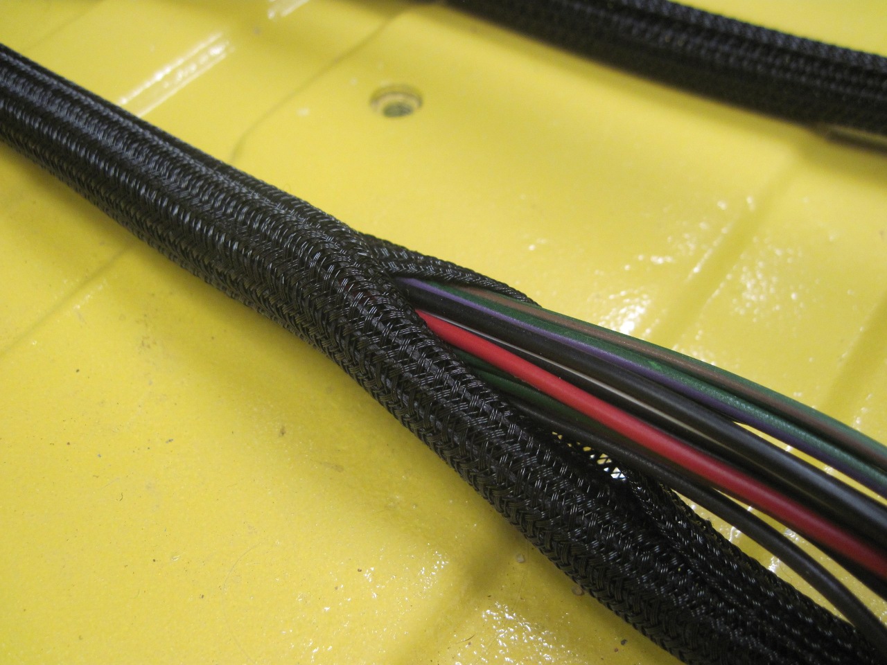
At breakout points, I sometimes used heat shrink to hold the sheath in place.

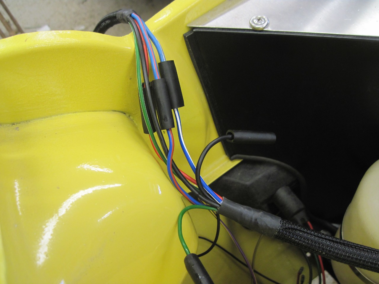
Here is the breakout for the left front lights. The cable then continues across to the other side. I use the stock style bullet connectors, but I load them up with dielectric grease before inserting the bullets.
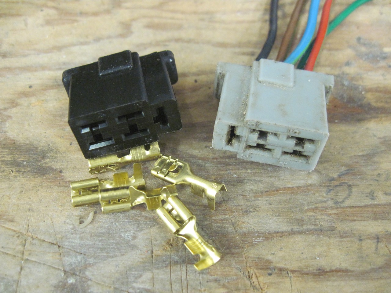
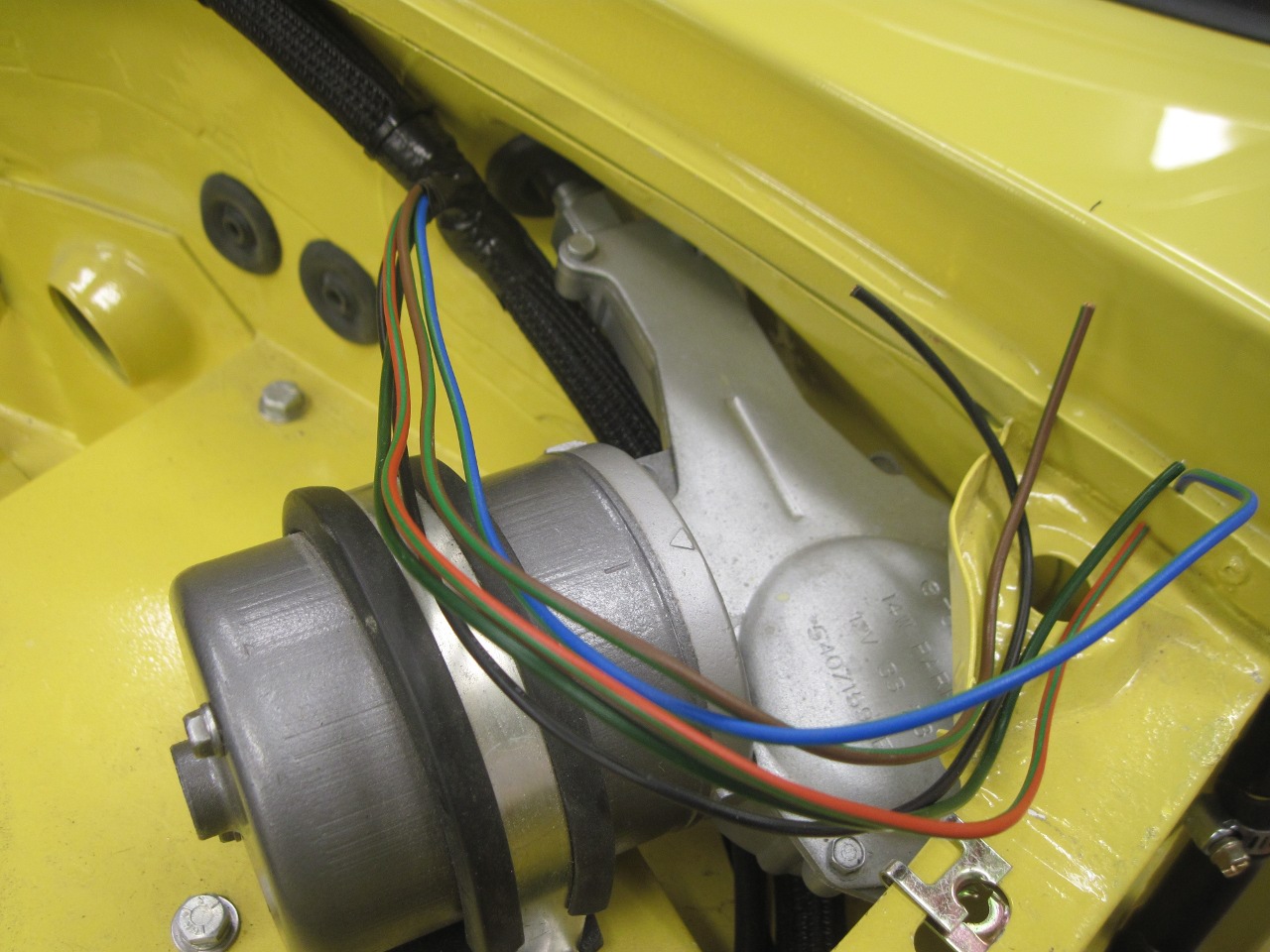
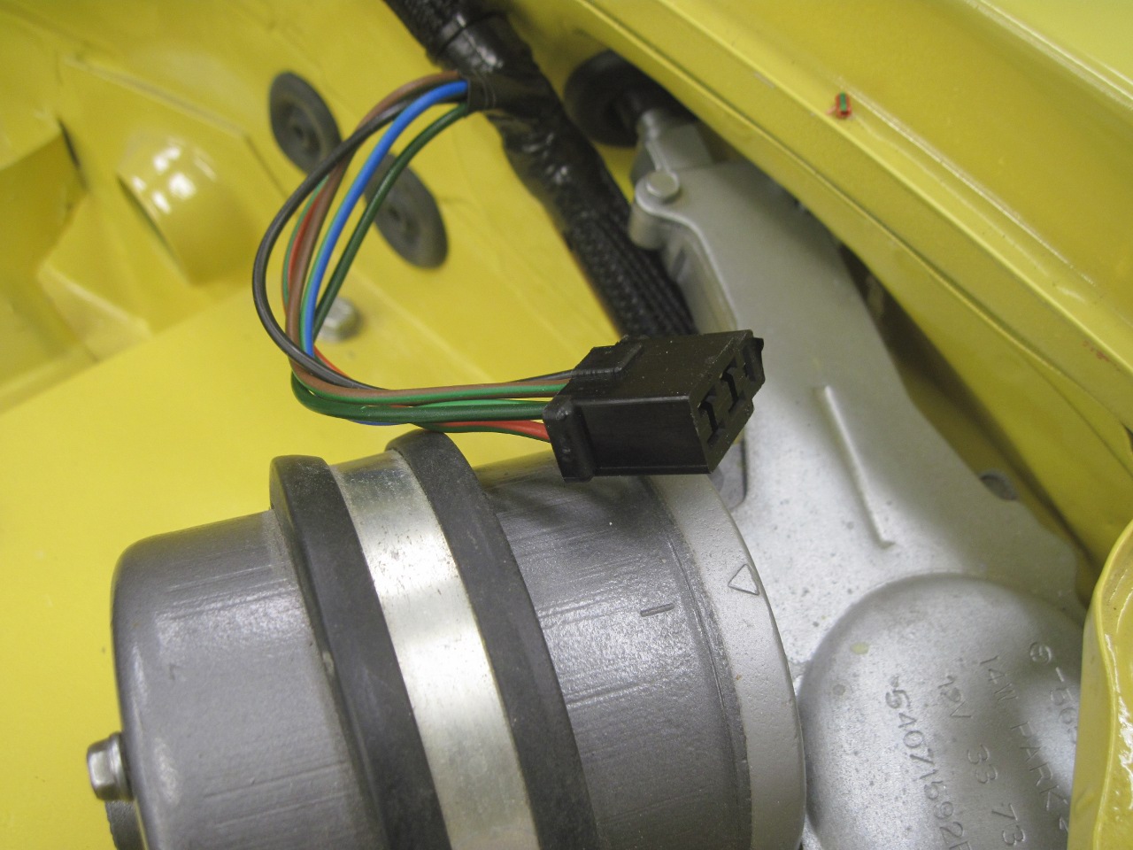
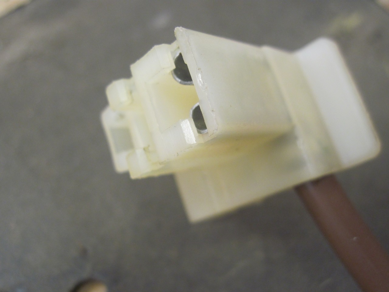
The connection to the wiper motor got a new plug.
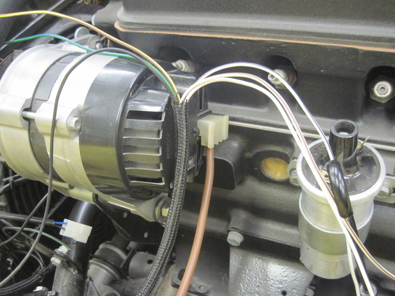
I
was able to save the alternator connector housing, but loaded it with
new wire and terminal. I went with 120 strand wire for the
alternator feed to the battery, which is similar to AWG 8 gauge.
The 18 ACR alternator is allegedly capable of 45 amps, and I
thought the original 84 strand wire a little undersized for that.
The other wires in the bundle go to the
temp sensor, coil, and OP switch.

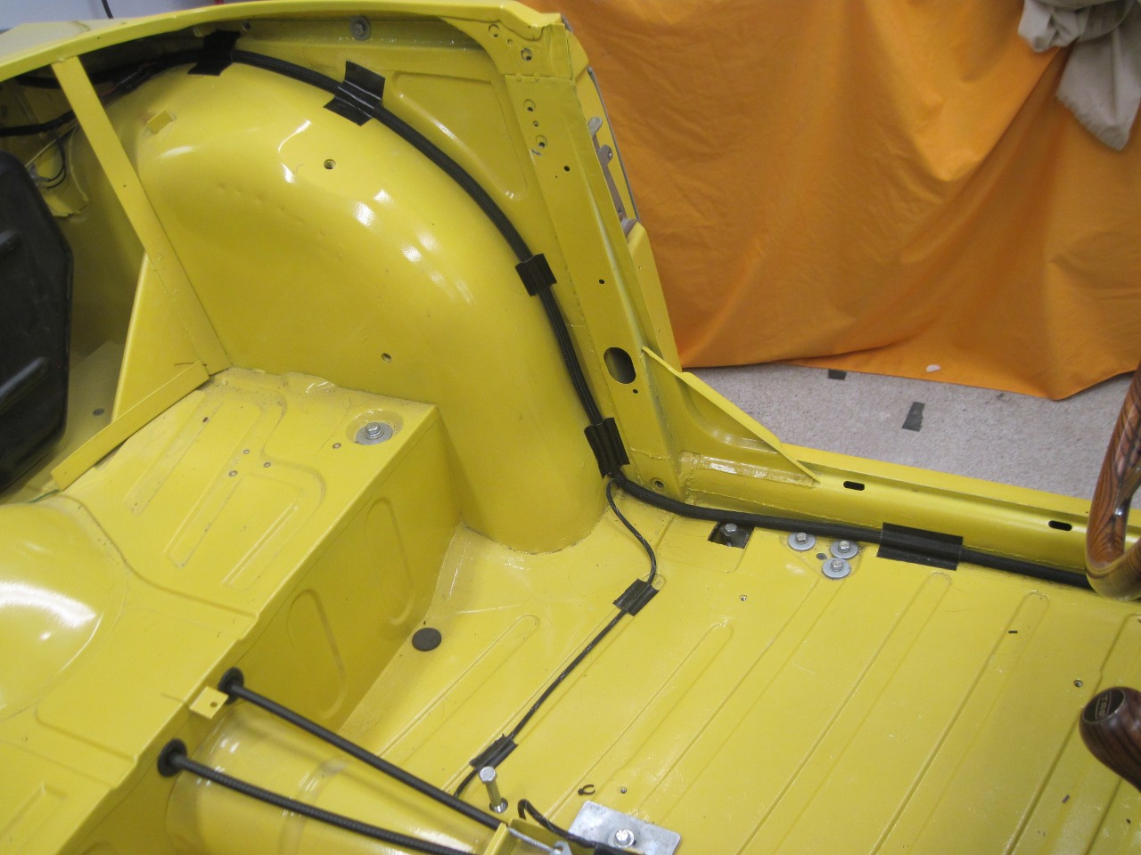
The rear lights.
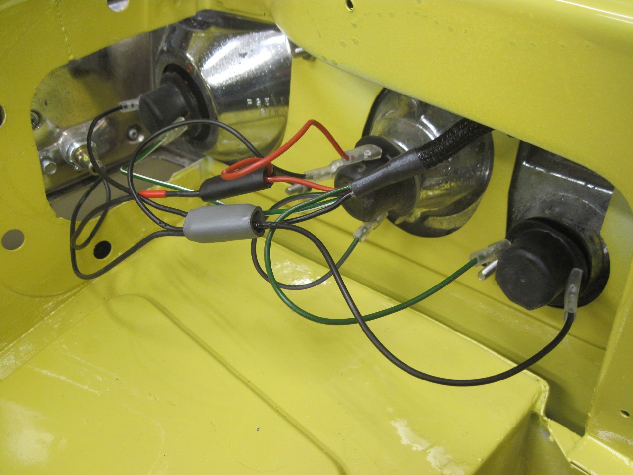

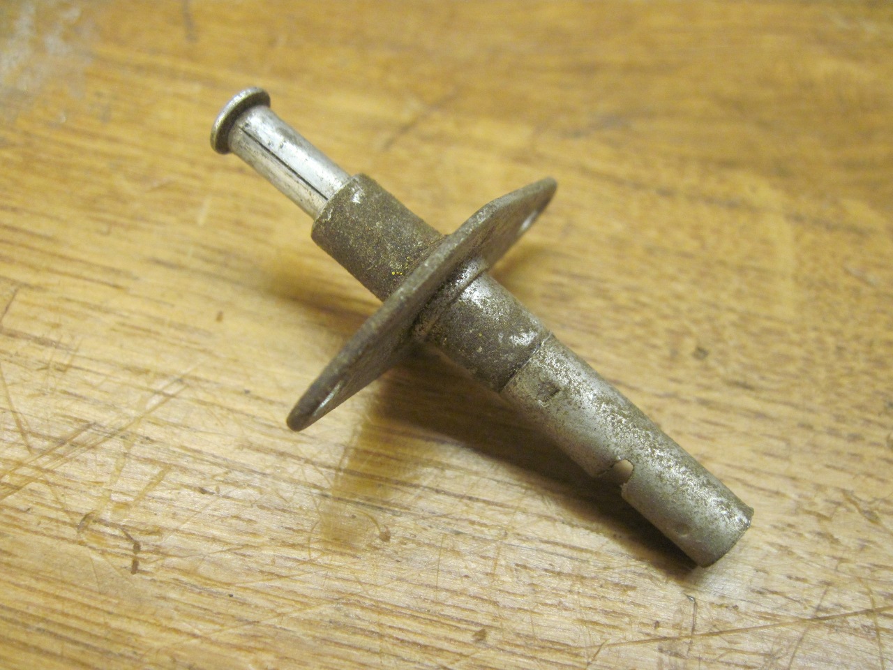
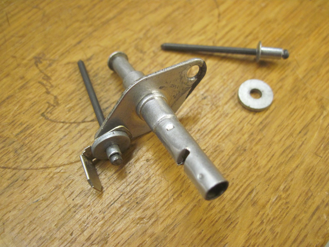
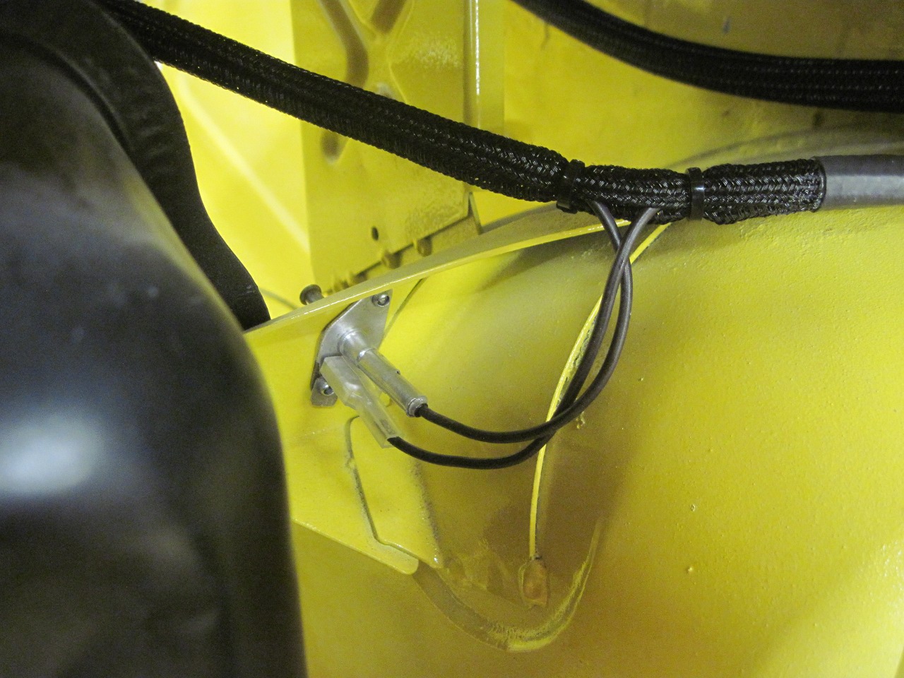
Cable routing was in general similar to stock. The small branch across the floor pan is for the hand brake switch.
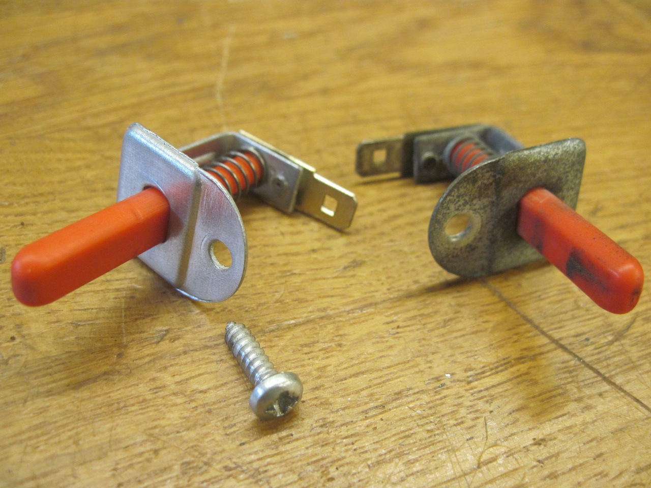
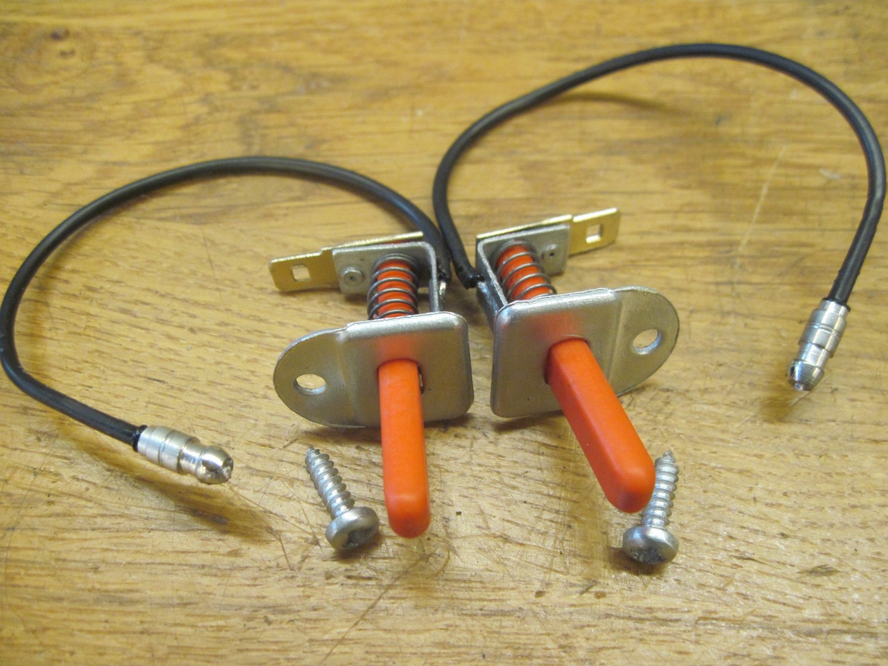
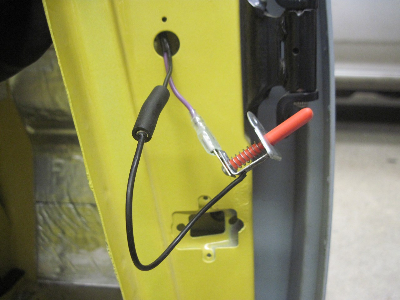
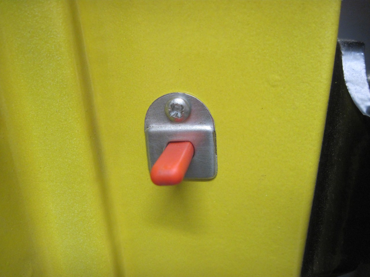
The boot light switch was modified to have a wired ground.
Ditto on the door switches for the courtesy lights.
Ground for the steering column goes into the harness rather than to the body.
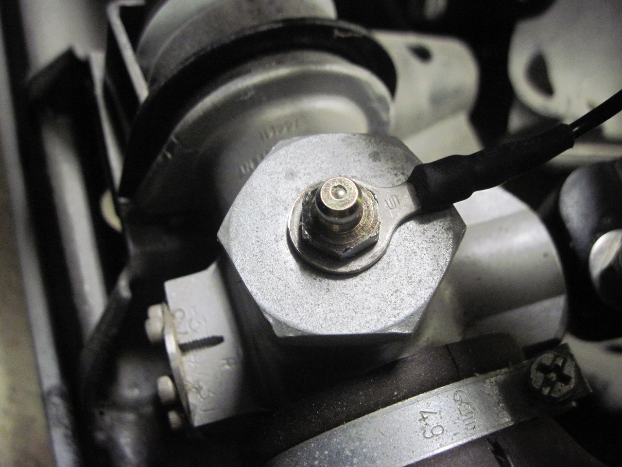
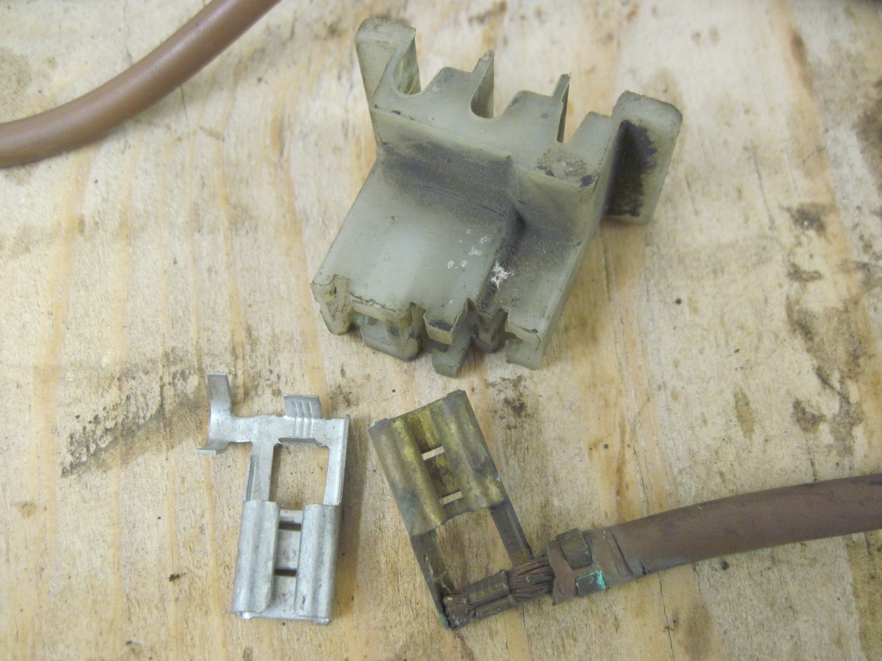
I
found this rubber boot for the radiator fan switch. The switch
is pretty low on the coolant pipe, and I was worried about the
terminals getting wet.

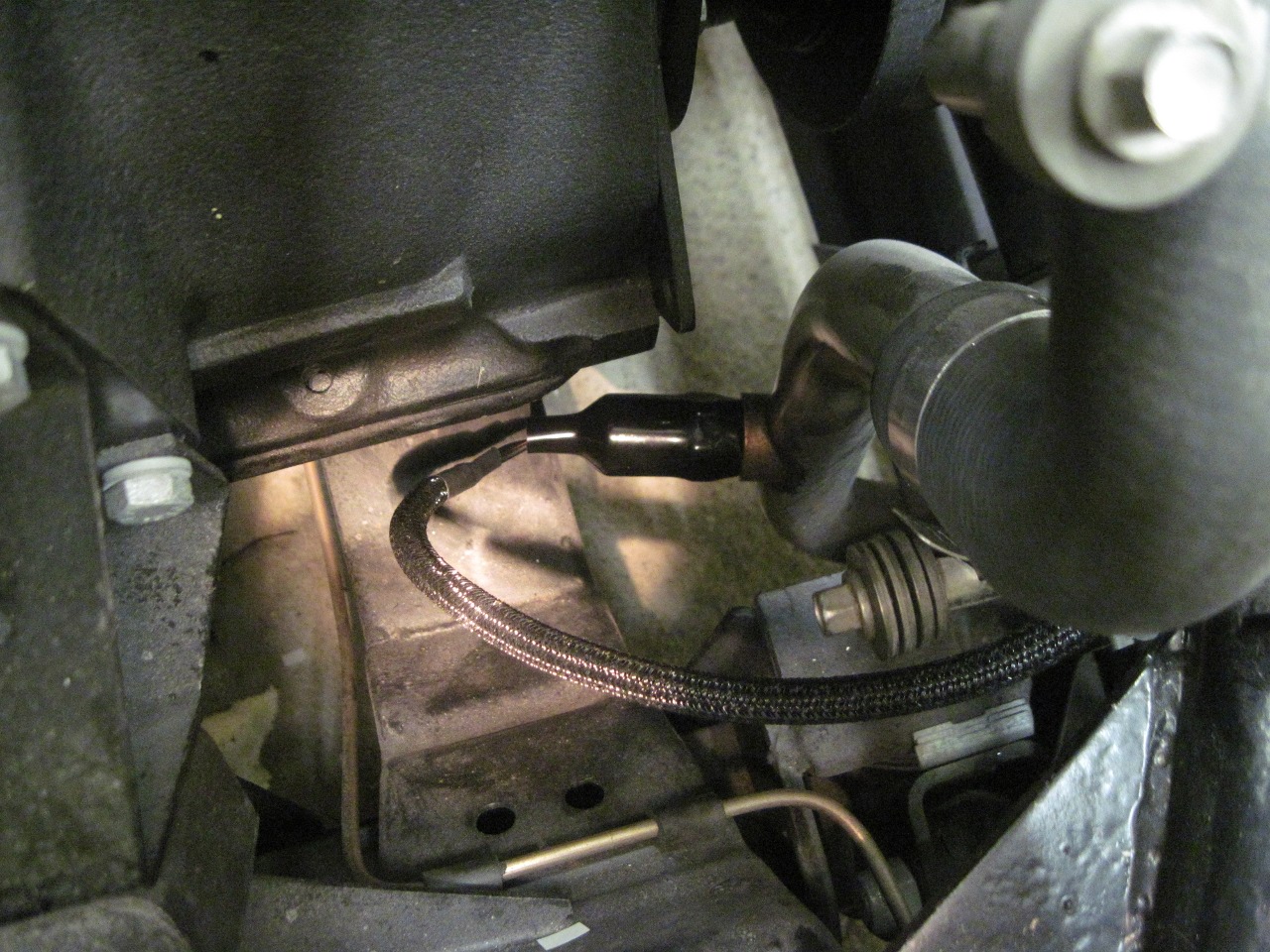
And the new fan connectror.

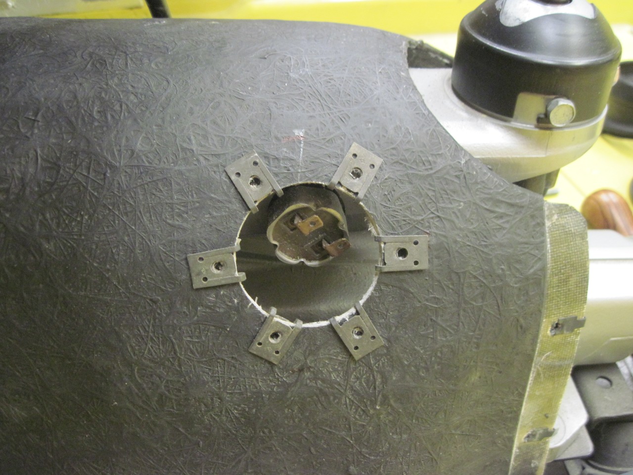
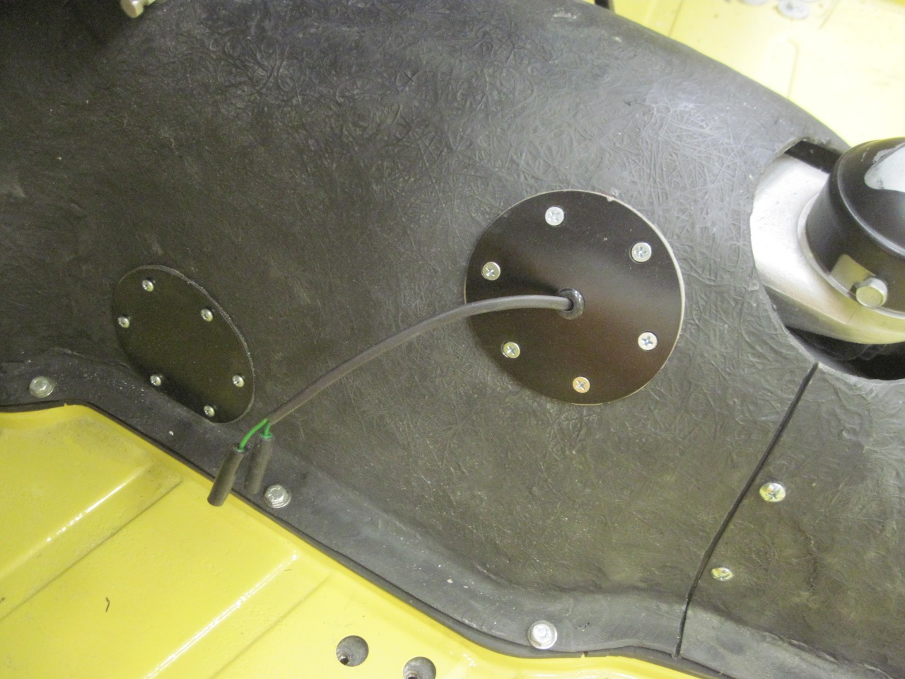
Here's
an oops moment. I couldn't get to the reverse switch. I
decided it was easier to cut an access hole and make a cover than to
remove the tunnel.
So now it was time to connect the PM end of the cables. Forty-five wires.

There are 17 return wires terminated on the ground bus.
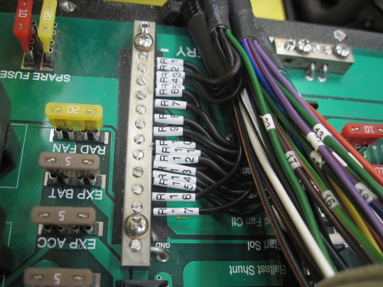
Everything in its place. Hopefully.
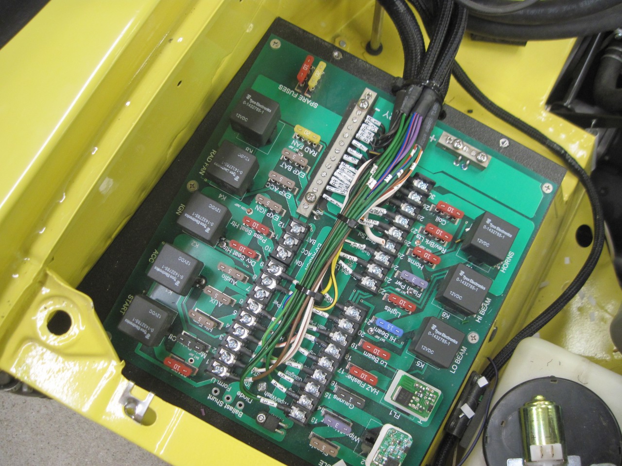
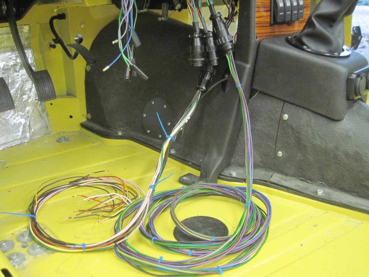
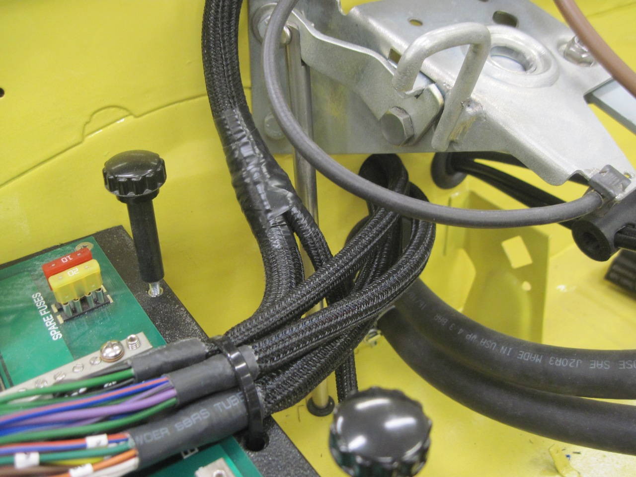
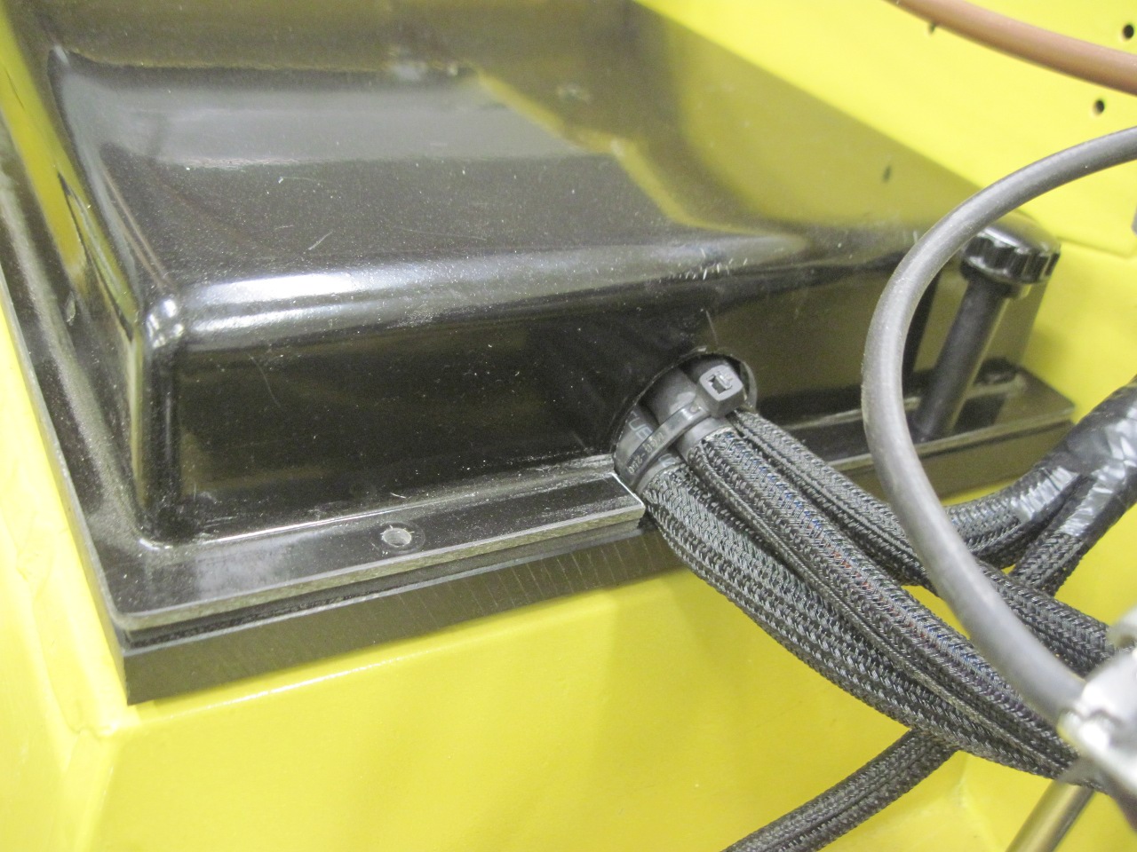
Here
are the four cables coming into the PM. Three come through the
hole under the bonnet latch formerly for the choke and heater control
cables. I moved those cables to the adjacent hole formerly for
the wiring harness. It just looked better that way. I added
a rubber grommet to the hole after these pics were taken.
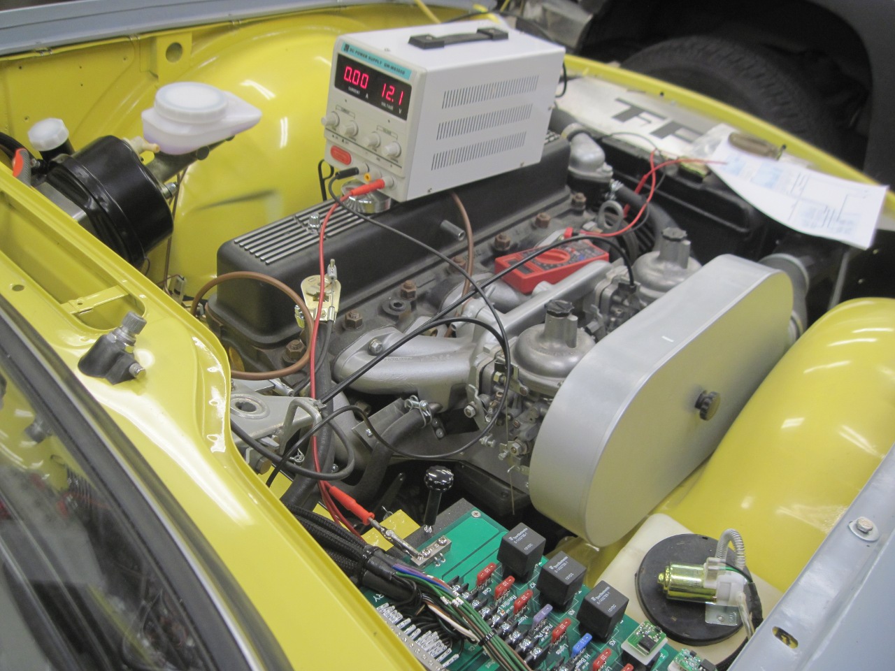
Now
it was sweaty palms time--time for testing. Instead of a battery,
I used this power supply that can be set to limit current. That
way, even a short somewhere won't damage anything, but will be
detectable.
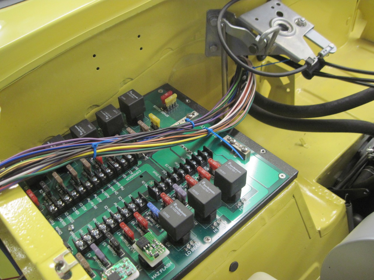
The
diagnostic LEDs on the PM helped a lot. For each relay, a yellow
LED comes on when the coil is energized, and a green one that comes on when
the relay operates. The greens are a lot brighter than the
yellows. This is with the ignition switch in the ignition
position, so both the ignition and accessory relays are energized.

Testing
went pretty well. There was one case of swapped wires that
stumped me for a while, but it was fixable. I cut an entry hole
on the PM cover. Still need to make the battery hot and ground
lead connections, but I don't have a battery yet.
This
effort was by far the most time intensive in the whole project.
For each hour in actual wiring, I probably have three or four in
planning and paper design. The materials cost was probably more
than what a commercial system would be, but of course it has a higher
level of customization. The down side to that is that now I'm
probably the only one who can fix it.
Commnets to Ed at elhollin1@yahoo.com
To my other TR6 pages