To my other TR6 Pages
January 18, 2017
Power Module
I
consider the factory electrical system to be one of the weakest parts
of TR6 cars. TR6s weren't alone in this. Many British cars
of the era had similar systems. Beside the fragile switches and
underpowered electric motors, the design made minimal use of
relays, and ran everything on only three fuses. Add to this the
dirt simple lamp holders and unreliable body grounds, and it's easy to
see why Lucas is the butt of so many jokes. If there is one
system on this car that cries out for an upgrade, it's the electrics.
There
are, of course, vendors who know this, and who offer a range of
aftermarket products to enhance the reliability of the electrical
system. One popular upgrade is to add a central power management
device. There are at least two of these products available, and
they both add relays to key functions, and split out more individual
circuits to their own fuses. I've looked pretty closely at both
of these products, and though they differ in philosophy in some areas,
they both appear to be well thought out and well made. I'd
consider either one of these devices a worthwhile modernization of the
TR6 electrical system.
However,
designing electronic circuits like this is something I did as a
job once upon a time. I thought it might be fun to dredge up some
old skills and have a go at making such a device of my own. This
would allow some customization, and implementation of a few things that
I think are important.
I
decided to make the device, which I call the Power Module, PCB (Printed
Circuit Board) based. This is a little problematic right off the
bat, since there are some fairly high currents that need to be handled
by the relays, and high currents require wide copper traces on the PCB.
This would make any attempt at miniaturization a challenge.
This is one reason I decided to mount the Module on the small
deck above the windshield washer bottle on the passenger side of the
engine compartment. There is plenty of room there, access to
relays and fuses would be very good, and cable routing shouldn't
be a problem. A relatively large PCB would allow spreading the
relays and fuses out, with plenty of room for legends.
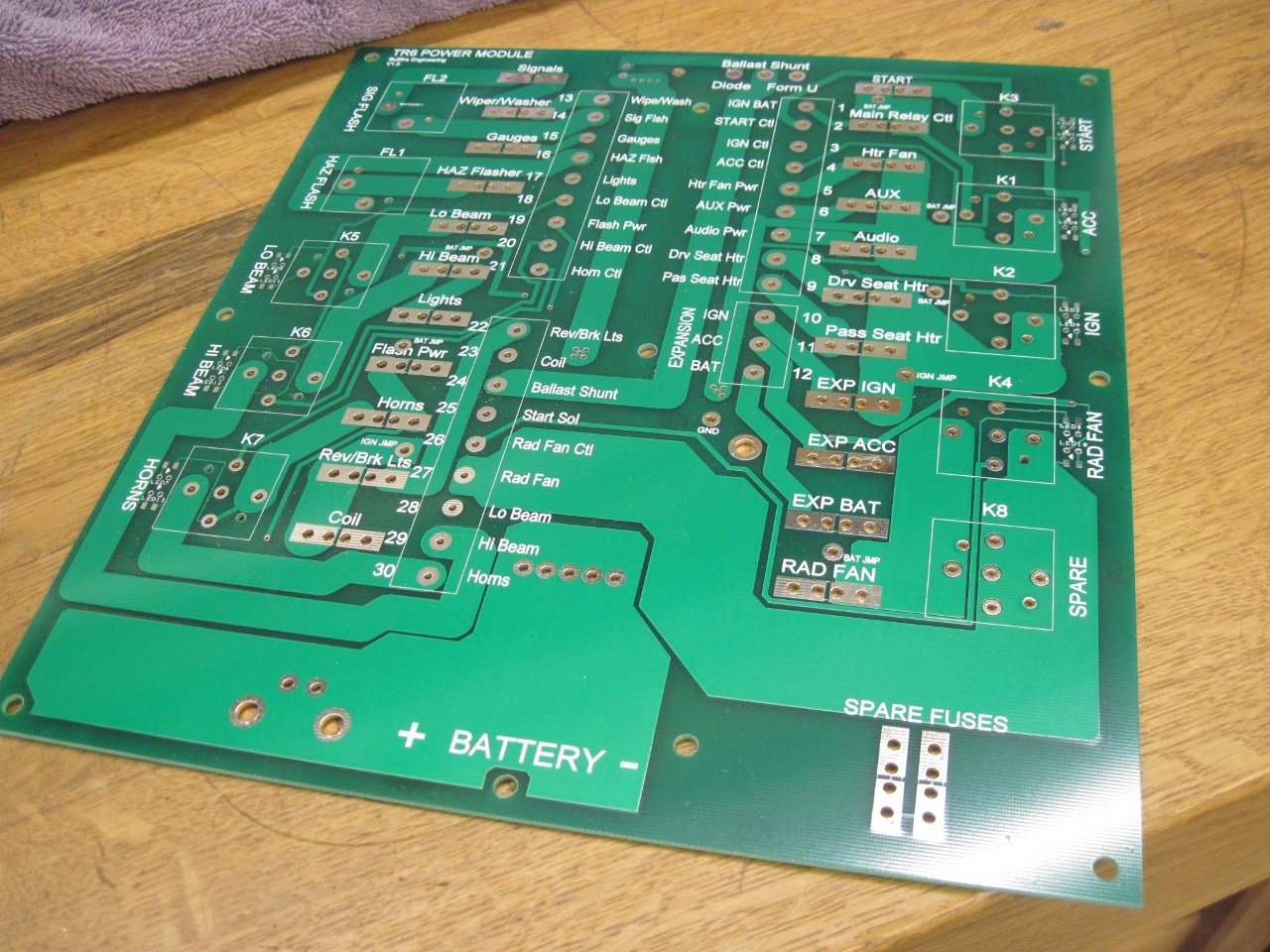
Here
is the bare PCB. It's about 9" x 10". The second picture
shows the standard relay and fuse sockets, and the barrier strips that
will populate the board.
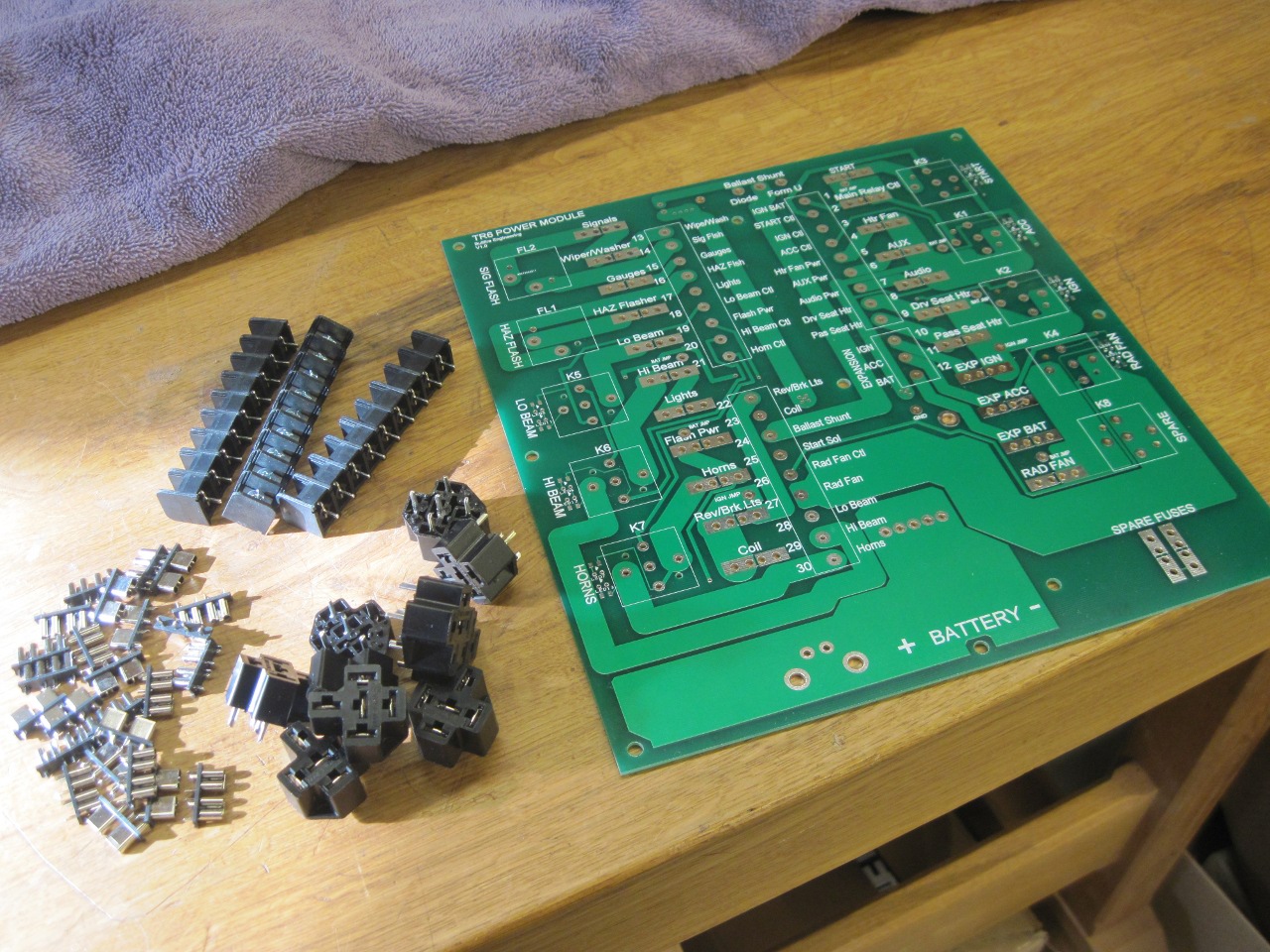
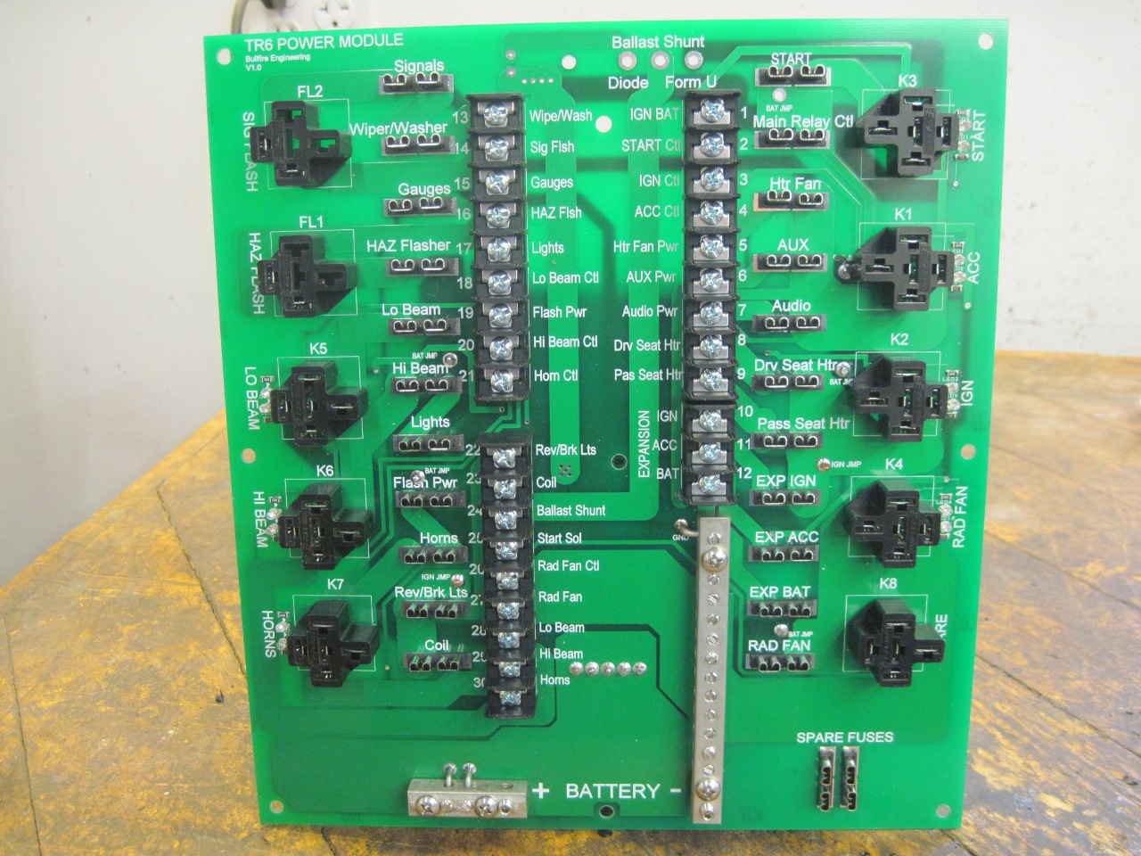
Here
are all the sockets and strips mounted. The long vertical bar
near the bottom is the return (ground) bus. Return circuits from
all over the car, including some that used to use the car itself, will
terminate there.
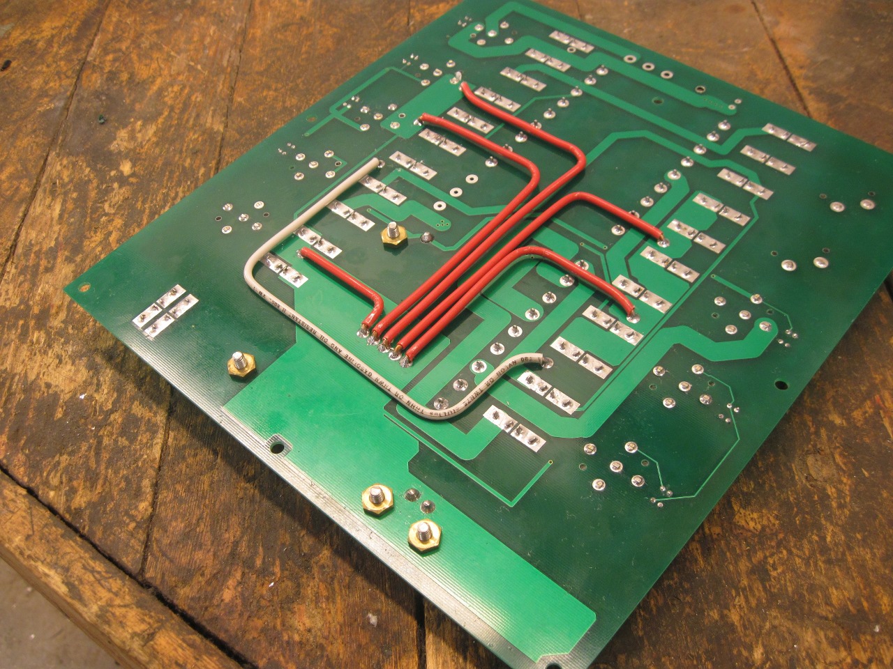
Even
with some traces as wide as I could make them, I wanted a little more
safety margin, so for a few higher current traces, I added
supplemental 12 gauge copper jumpers on the back of the board.
Here
is the board fully populated with relays and fuses. Instead of
bringing wiring to connectors on the perimeter of the board,
wires will come up the center of the board, and fan out th their proper
connection point. With a cover on the Module, this should give a
neat appearance with all wires entering in a single bundle.
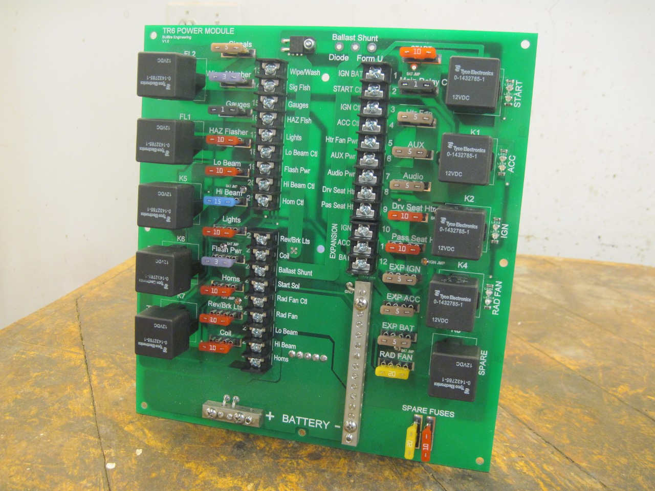
My seat heater kits came with inline fuses, but I'd rather have them with all the others.

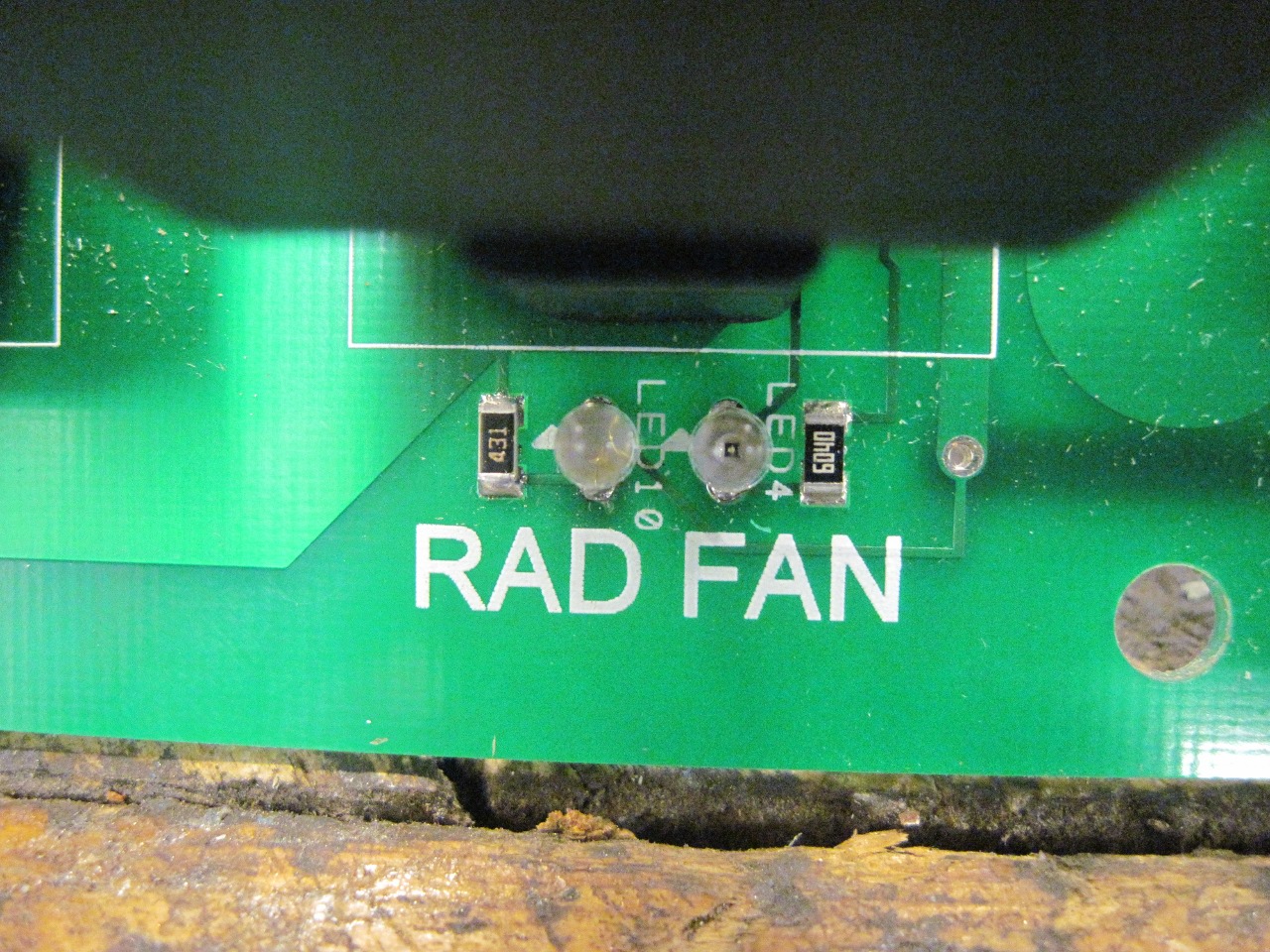
Other
features included in the design include diagnostic LEDs on each relay's
coil and power contact. With power to the coil, the right yellow
LED will light. With power on the switched contact of the relay,
the left green one comes on. So in all cases, both the yellow and
green LEDs should light when the relay is activated. Yellow and
no green would suggest a bad relay or possibly a blown fuse.
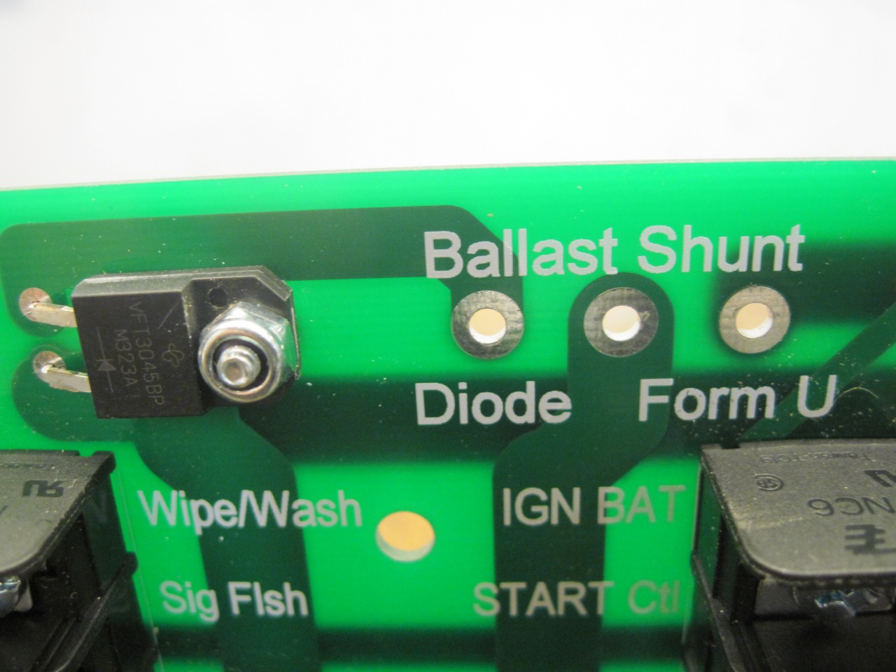
There
is a provision, through the use of jumpers, to use either of two
methods to accommodate ballasted ignition systems. A ballasted
system uses a coil designed to run at a primary voltage well below
battery voltage. The voltage drop is provided by a ballast
resistor (which may actually be a piece of resistance wire) in series
with the coil primary. To help with starting, the ballast is
bypassed (shunted) during cranking. The shunting can be done with
a special "Form U" relay in place of the START relay, or with a diode
to prevent backfeeding through the shunt connection. Some
TR6 cars, including mine, used a Form U start relay. (The Form U
relay is one that uses a dual SPST arrangement rather than the normal
Form C SPDT.) For an unballasted system, neither jumper is
installed.
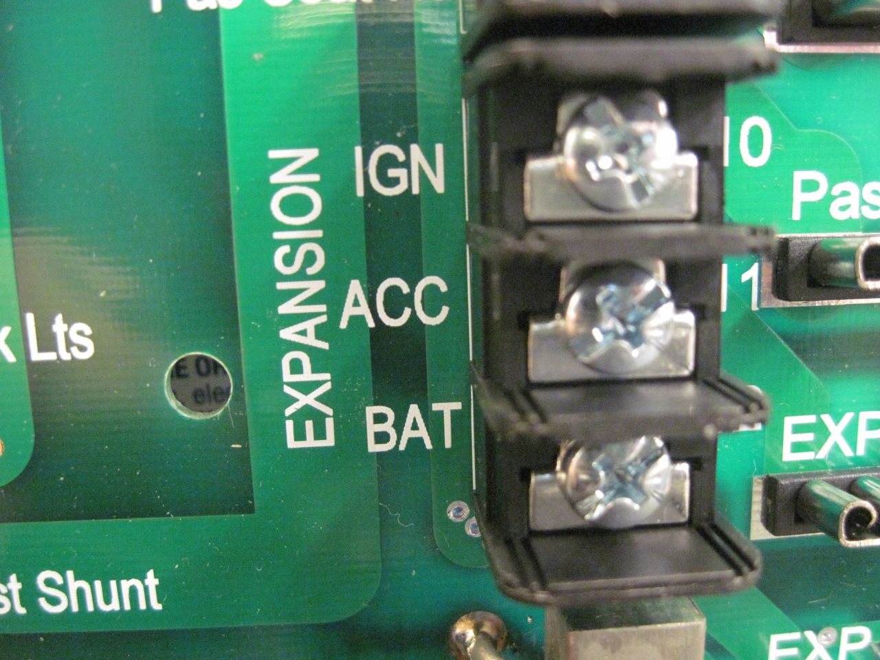
To
allow for unanticipated future needs, I included three undedicated
fused circuits, one each on the BAT (always hot), IGN (ignition switch
in the run position) and ACC (ignition switch in run or accessory
position) circuits.
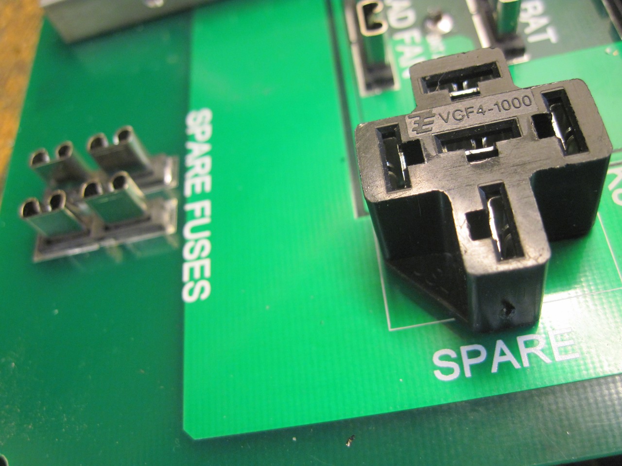
I had a little extra room on the board, so I included some dummy sockets to hold a spare relay and a couple of fuses.
As
tasks go on this project, the Power Module is one of the most
time-intensive. Actually putting it together was trivial by
comparison. As far as cost, I probably could have bought a
commercial unit a little cheaper, but it certainly would not have the
level of customization. Though the Power Module itself tested out
fine for functionality, I'm a little concerned about rubustness.
I used a very standard PCB material and thickness, and while I
think it should be adequate, it probably wouldn't take much rough
handling. Stronger, thicker board material was quite a bit more
expensive, and I wasn't ready to say this is the final design of the
Module.
Comments to Ed at elhollin1@yahoo.com
To my other TR6 Pages