To my other TR6 pages
December 21, 2016
Dashboard Pre-Wiring
I
think the wiring on my car was mostly OK, but I had a
few improvements I wanted to make. First, there were some
original devices that I decided to eliminate. For example, the
anti run-on switch, the seat and seat belt sensors, and the ignition
interlock circuits would not be included in the refurbished car.
There were also some new devices--seat heaters, radiator cooling
fan, and some USB power outlets, for example. I also wanted to
re-think the Triumph philosophy of combining many circuits into just
three fuses. One danger of this approach is that with multiple
circuits feeding from one fuse, the fuse's rating must be high enough
to cover all of its loads. I believe it is conceivable that a
partial short in one of the circuits could easily draw enough current
to melt the insulation on its wiring, while still not blowing the fuse.
Further, I wanted to modernize the electrical system by adding
more relays. This would ease the load on dash switches and
eliminate the need for large wires behind the dash.
I also
wanted to improve the grounding on many of the loads on the car.
Using the body as the circuit return path, while common, is not
ideal. Ground joints, many with dissimilar metals and subject to
moisture and corrosion, were a notable weak spot on these cars.
Wherever I could, I wanded to provide explicit copper return
paths from loads to the battery negative.
With these and a few
other enhancements in mind, I decided that rather than trying to modify
the existing harness, it would be easier to just start from scratch.
With it being cold in the garage, I decided to start
with the dash in the shop. I'd like the dash to be electrically
as self-contained as possible. Ideally, I'd like to be able to
remove the entire dash along with most of its wiring by just
disconnecting the speedo and tach cables and the oil capillary, and a
few electrical connectors.
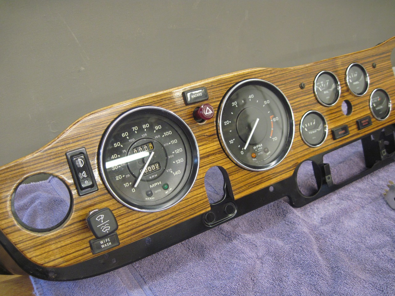
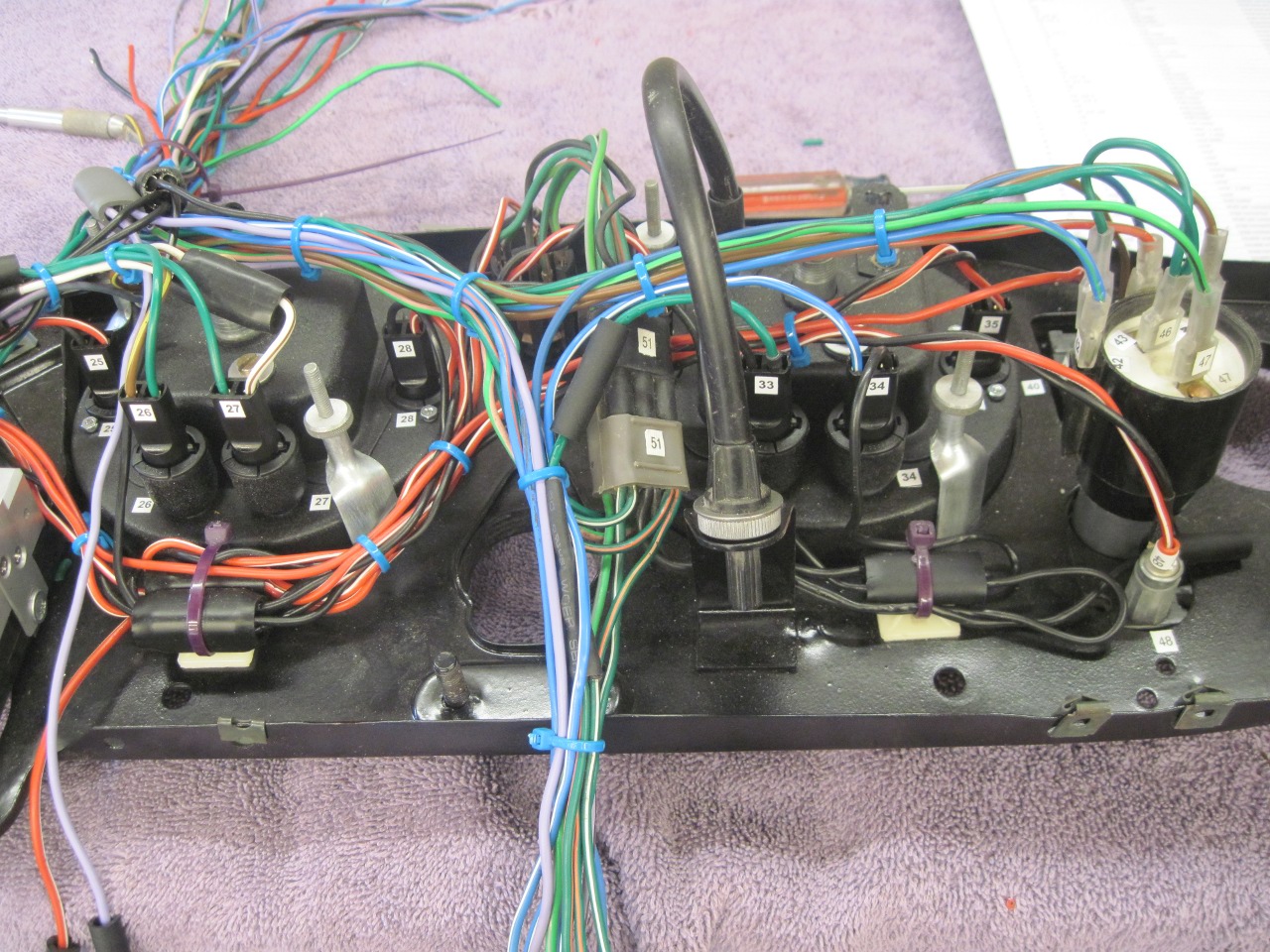
So, first, I populated the dash with
all its gauges, lights and switches, then flipped it over so I could
work easily on the back side.
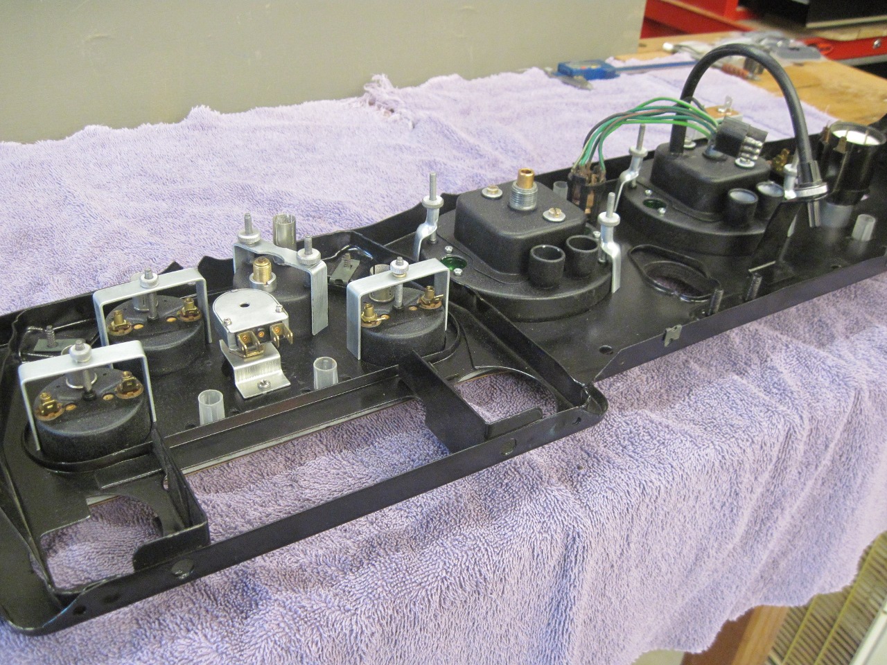
For
wire, I harvested good wire from the harness. I tried to stick
with the original Triumph color code for the most part, but with many
more fused circuits, this was not always possible. I also took
all of the dash lamp sockets from the harness to determine which ones I
could re-use.

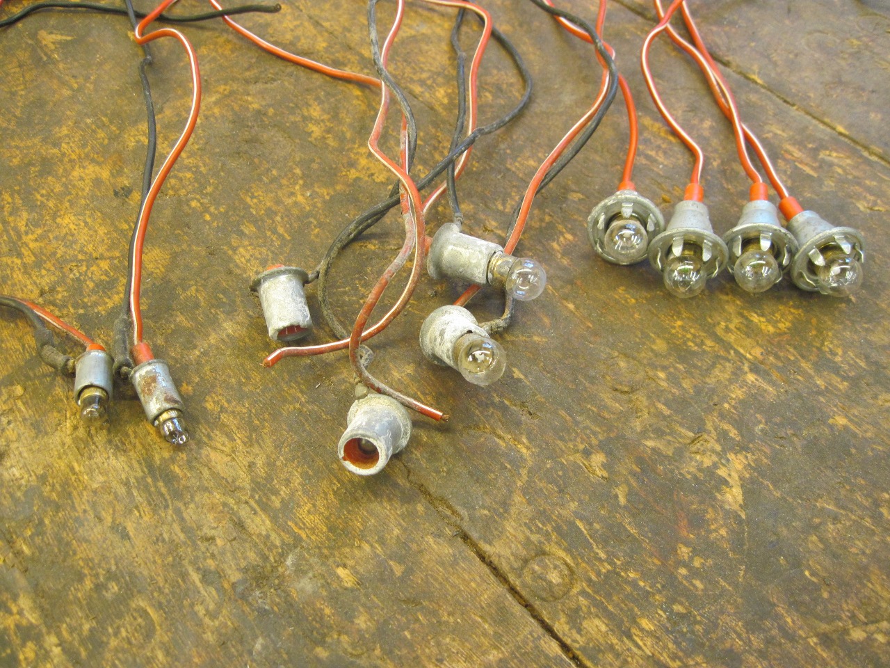
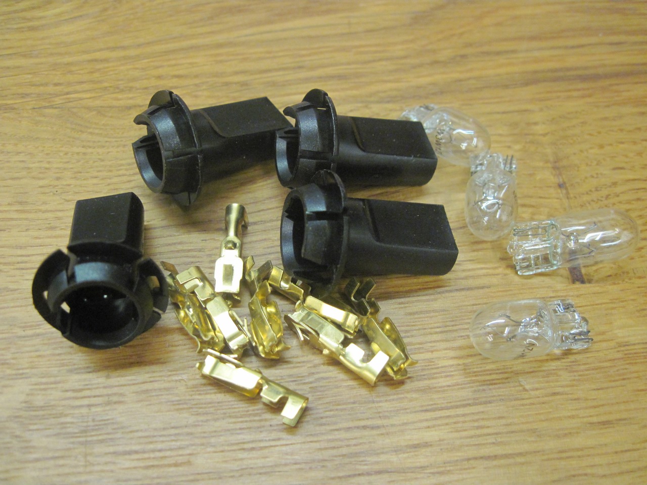
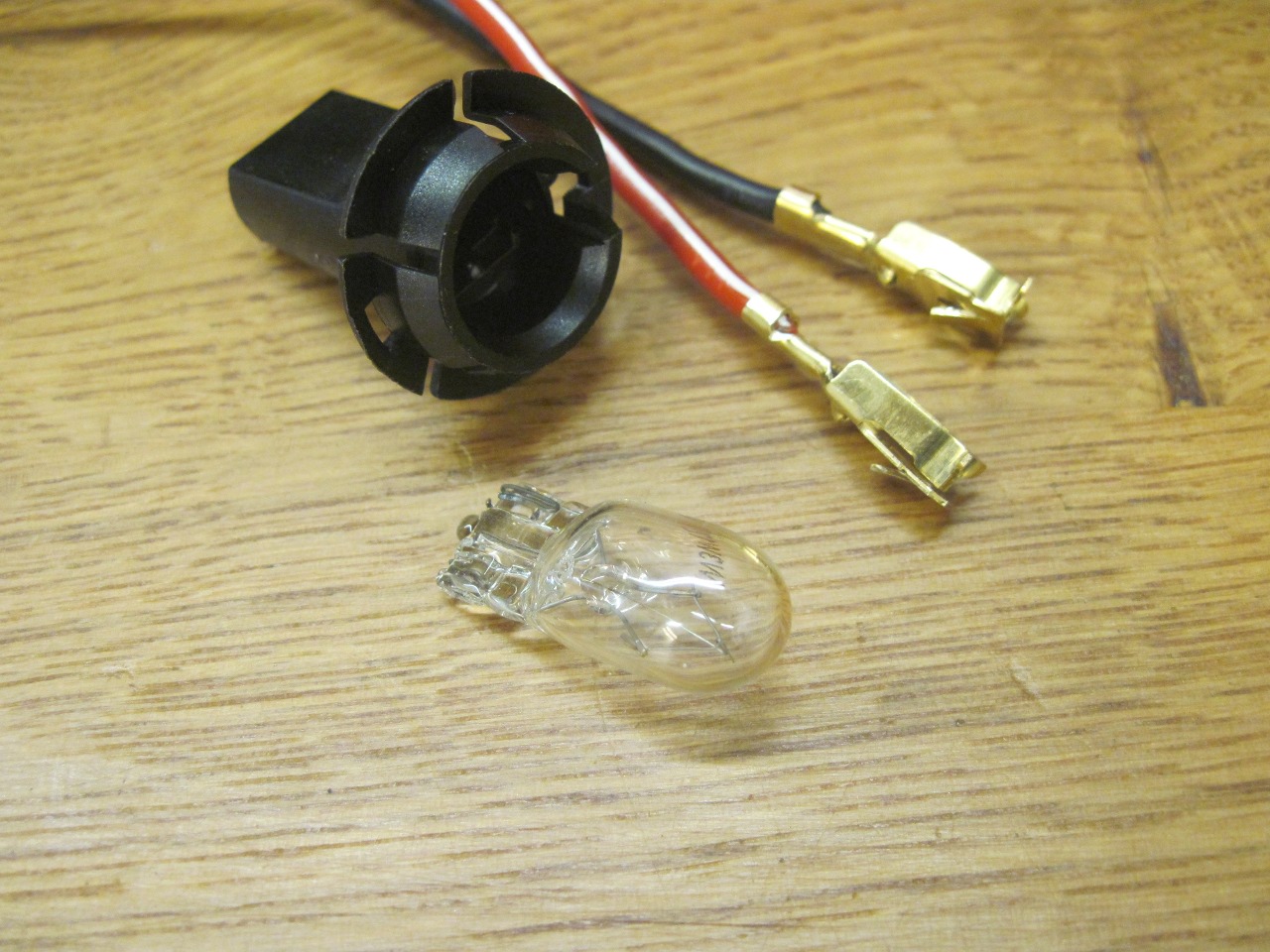
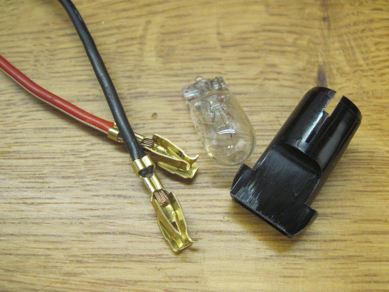
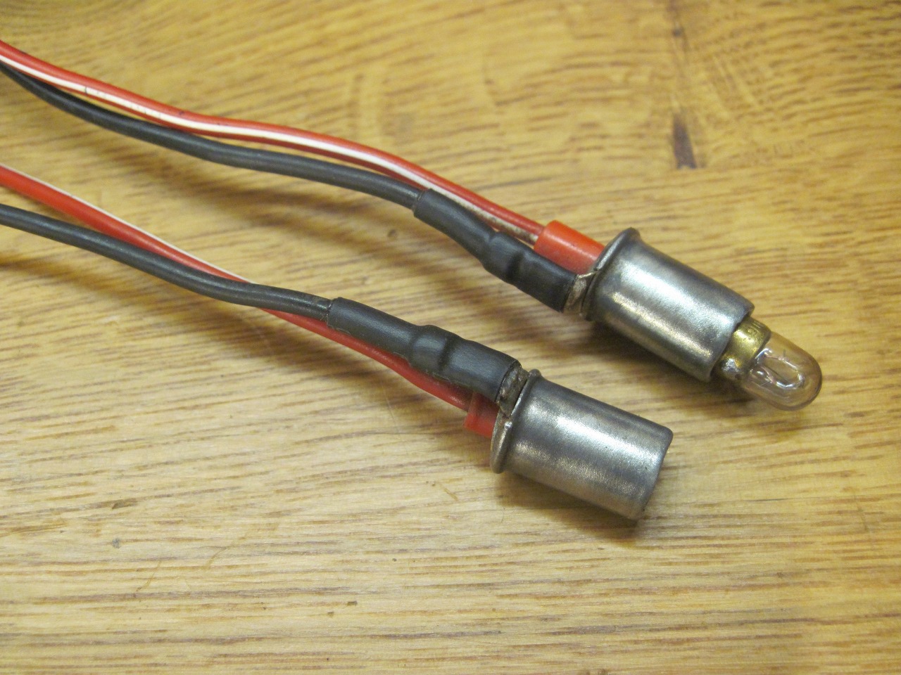
The
speedo and tach illumination lamp sockets were simple one-wire units,
and I didn't see a good way to add a ground wire to them other than
just soldering it to the side of the socket. Rather than do that,
I found these two-wire sockets that snap- fit perfectly into the holes
in the instrument cases. These sockets take modern wedge-base
bulbs of similar wattage to the originals. I also used these
sockets for the oil, ignition, hi-beam, and turn signal lights in the
tach and speedo.
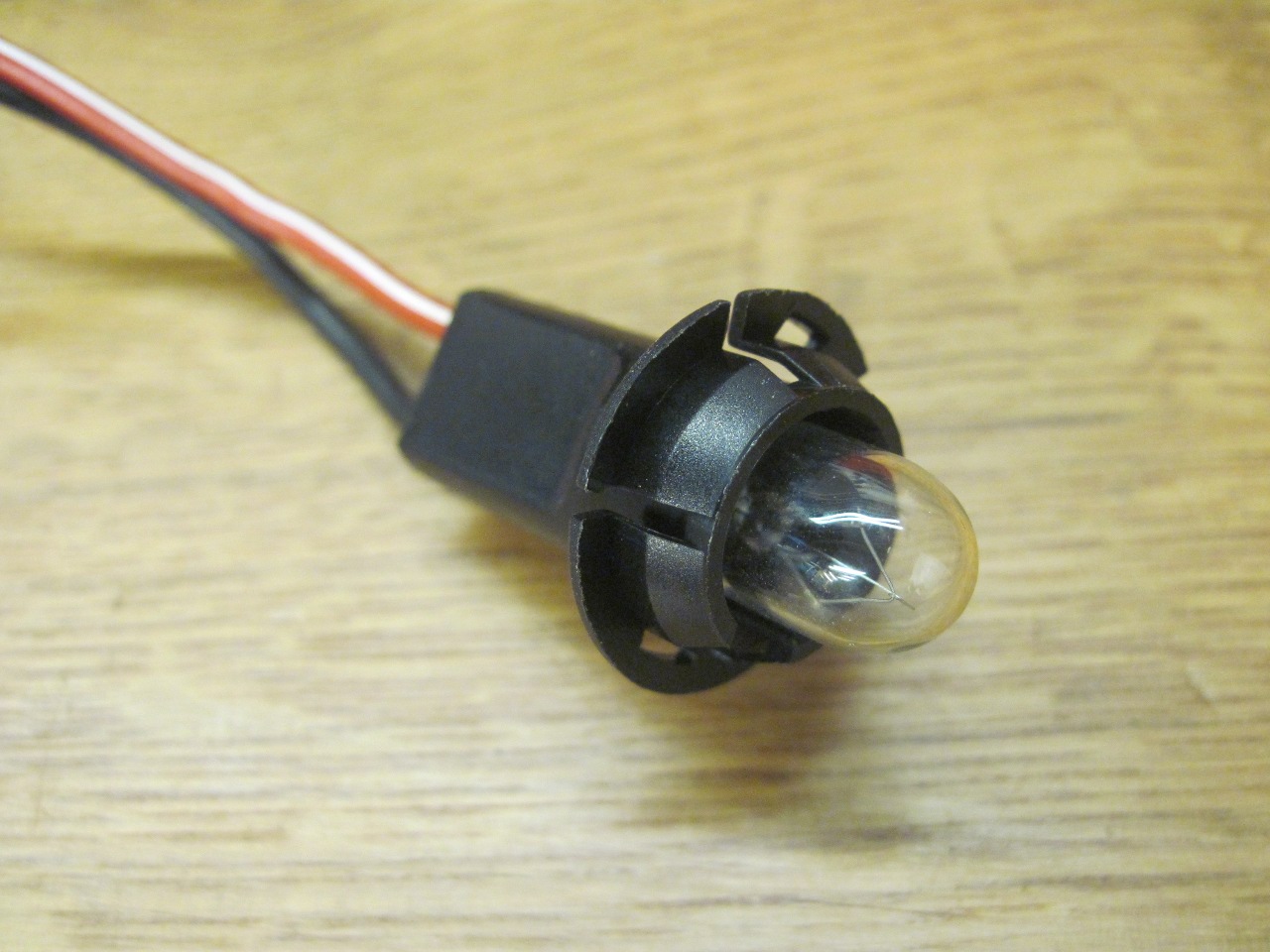
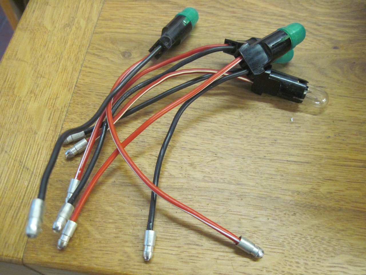
The
illumimation of the smaller gauges used a similar socket that would
slide into the smaller hole, but taker the same bulb. Since none of the internal green
filters in the gauges survived, I used the little green covers.
Red with a white stripe was the correct wire color for the lamps
on the dash dimmer circuit.
For
the wipe/wash and hazard switch marker lights, which also connect to
the dimmer circuit, I was able to clean up and re-use the original
sockets with their small BA7 bulbs.
.
So here is the dash with all the bulbs on the dimmer circuit wired.
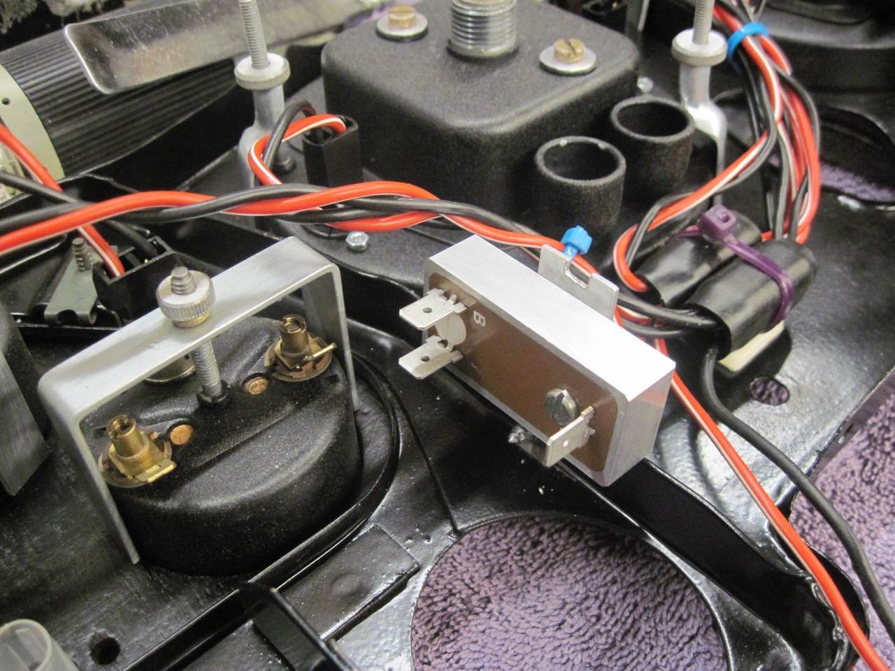
Before I went any farther with the wiring, I wanted to find a final place for the new gauge voltage stabilizer. It seemed to make more sense to mount it near the gauges rather than its stock location on the back of the speedo.


Now,
on to some other indicator lights. The BRAKE (PDWA) and the
new PARKING BRAKE warning lights also use the small BA7 sockets, which
I could re-use, but I had to change the wire colors.

Speaking
of the PDWA light, this is an area where I (and many others) consider
the wiring design a little funky. The PDWA light and the oil
pressure warning lights were wired such that when the oil pressure
switch was closed (signifying no oil pressure), the two lamps were in
series, so each would light, but dimly. When the PDWA switch was
closed, the BRAKE light would light to full brilliance. This
apparently served as a simple bulb test function on startup with the
ignition switch on, but the car not running.
I've seen
some ingenious improvements in this area involving relays, but I just
applied a simple diode mod that allows both lamps to show full
brightness during the lamp test (and also on oil pressure failure).
. 

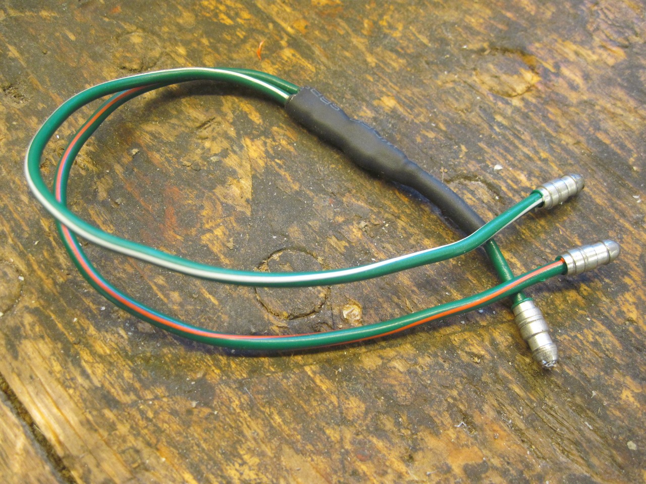
The diode was just soldered to a couple of bullet-terminated wires of appropriate color, and protected by heat shrink.
A
couple more diodes were used to modify the operation of the turn signal
indicator lamp on the dash. The factory just wired this lamp
across the two wires going to the outside turn signals. This in
effect puts the indicator in series with the signal lamps that aren't
flashing. Since the indicator is a much lower wattage than the
outside signal bulbs, the currrent that flow is enough to light the
indicator, but not the signals. This works fine for a stock
setup, but with LED lamps for turn signals, it may not. The
modified circuit should work regardless of the type of signal lamps.


The diodes were assembled into a pluggable module.


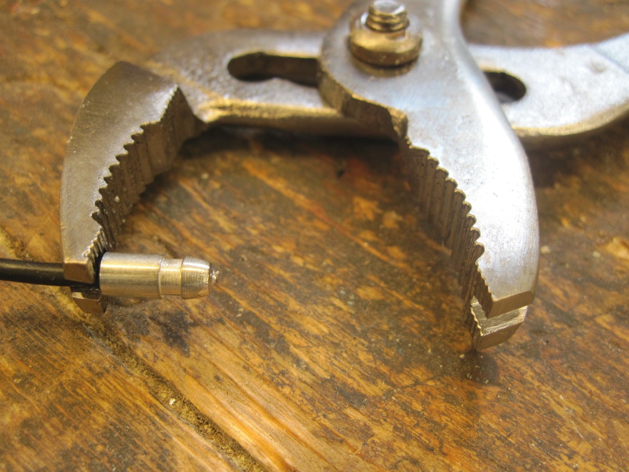
Incidentally,
having to insert so many of those ubiquitous Lucas bullet connectors
made me look into buying a proper insertion tool. All the ones I
found appeared really cheaply made for their price, so I improvised by
grinding a slot into the jaws of a pair if inexpensive slip-joint
pliers.
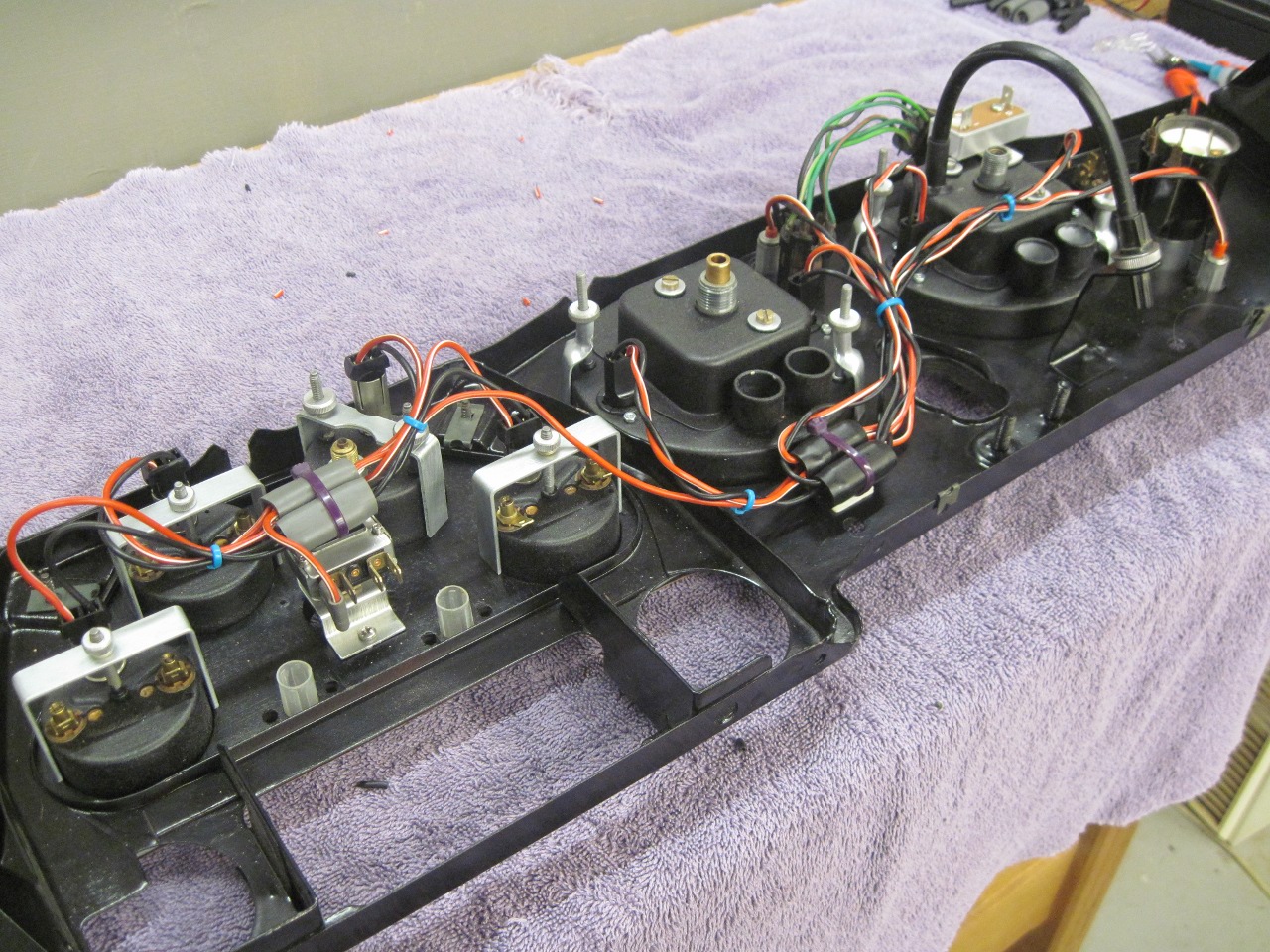
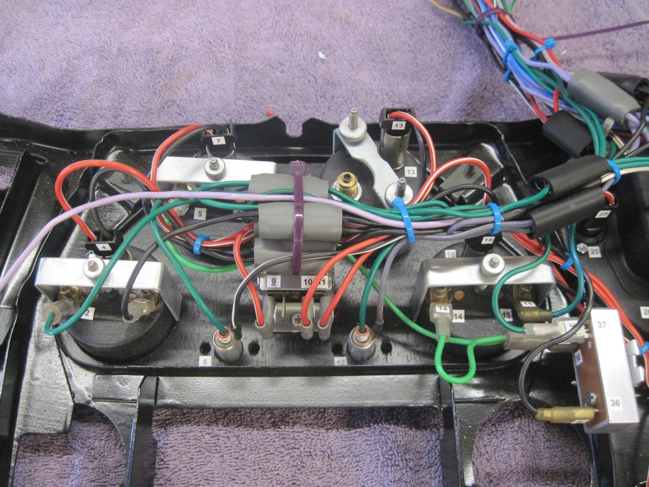
I
then proceeded with the rest of the wiring. The wires trailing
off near the lower right connect to the wires from the steering column
controls. The other two wires coming off the bottom of the dash
are for the plinth light, and for power to the courtesy lights.
The wires coming from the top of the dash go to various other
parts of the car.
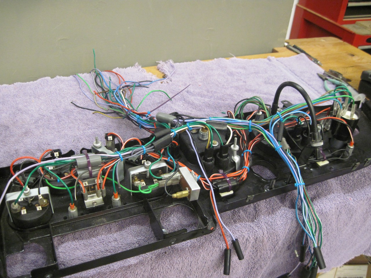
To save heartache in the future, I numbered all the connections according to the appropriate facia diagram.
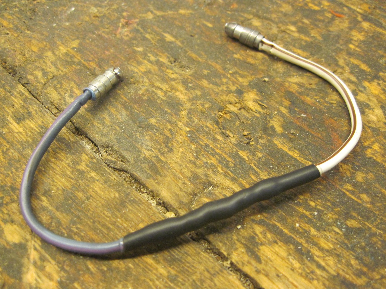
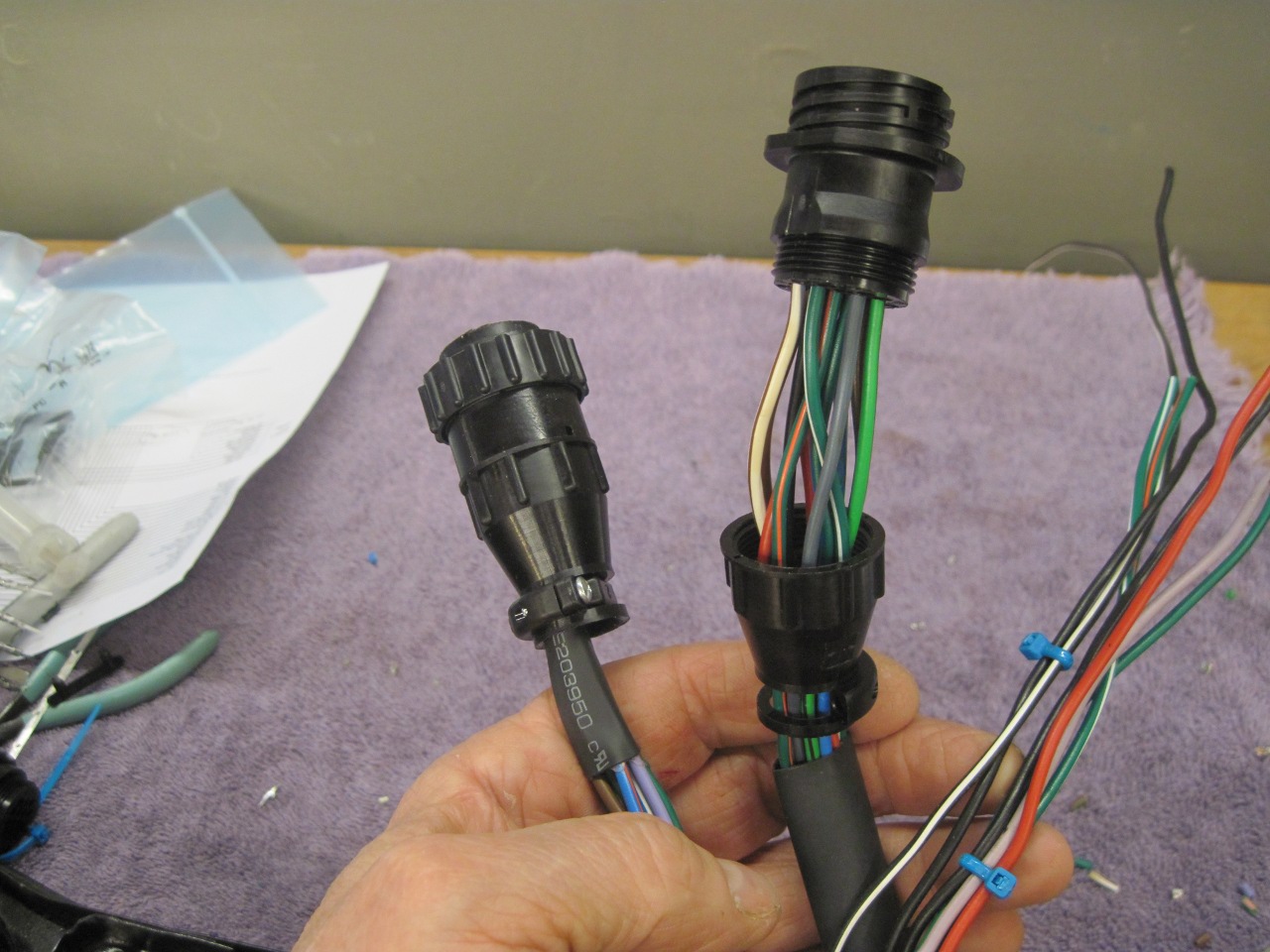
Then
terminated all the wires going elsewhere into three circular
connectors-one each for the cables going to the new power module, the
front of the car, and to the rear of the car.
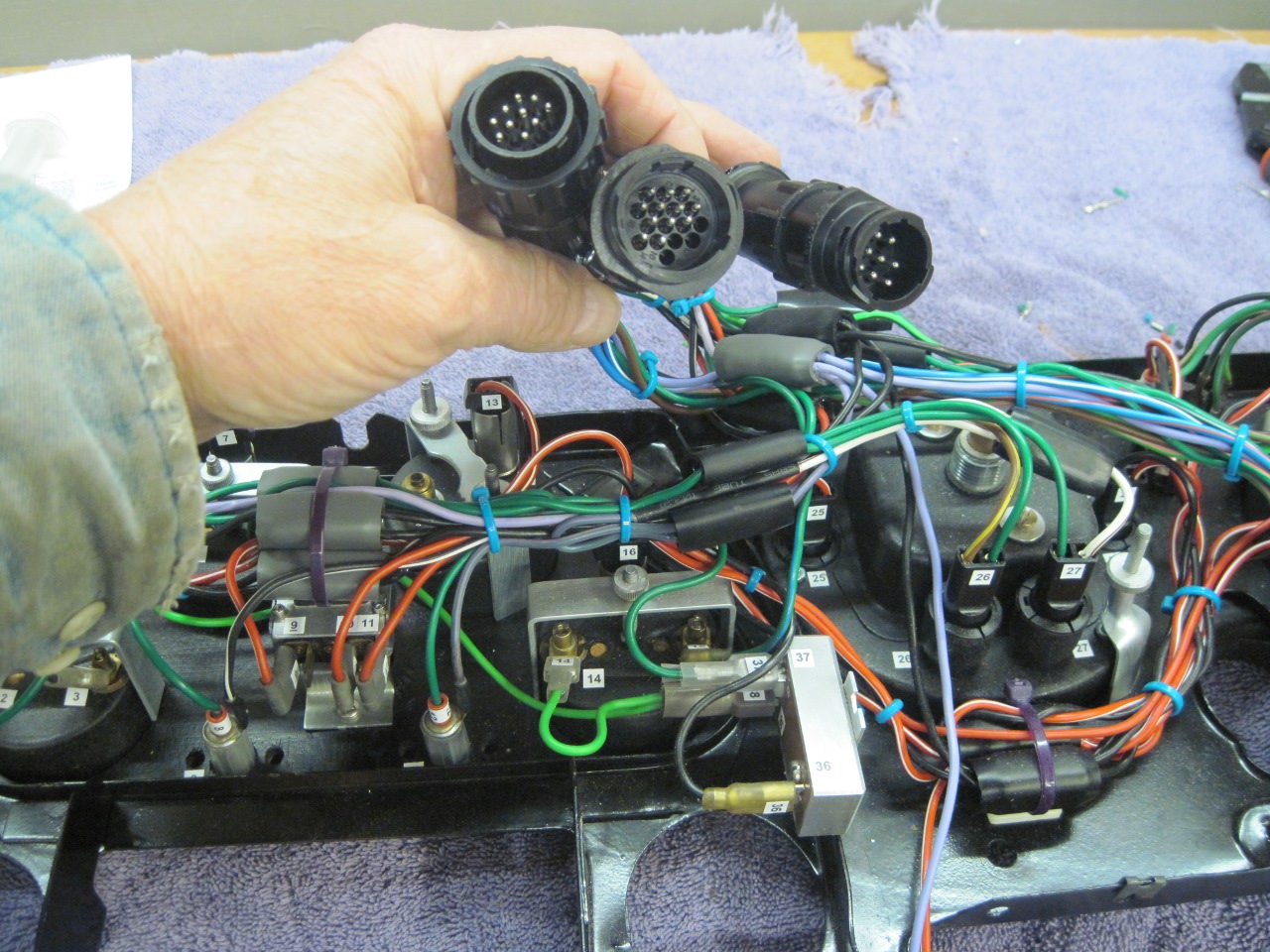
I'll make up some dummy mating cables for testing, but I need to get busy on the power module first.
This
was by far the task on this car that took the most planning. I
have more hours in working out schematics and cabling diagrams than in
actual wiring. The cost wasn't low, but not too bad. I was
able to use all original switches and instruments, and even wire, but
there were quite a few new lamp sockets and connectors. I
still have the option to go to LEDs for the dash lamps, with a
changeout of the dimmer, but the power savings isn't nearly as
high that for the outside lights, so at this point I'm not seeing
a huge advantage.
Comments to Ed at elhollin1@yahoo.com
To my other TR6 pages