To my other TR6 pages
January 22, 2014
Voltage Stabilizer
[Click the images for a bigger view]
The
fuel gauge and the coolant temperature gauge on my TR6 are electrical
instruments that respond to the current flowing through them. The
current is controlled by a varying resistance in the appropriate
sensor--the fuel tank float in the case of the fuel gauge, and a
resistive temperature sensor in the coolant stream for the temp gauge.
This arrangement works well, but it depends on a stable voltage
for the gauges to work with. A changing voltage will also vary
the current through the gauges, and affect their readings.
Unfortunately
for the gauges, the system voltage on this and most other cars can vary
pretty widely--from less than 12 volts to nearly 15. For this
reason cars of this vintage have a voltage stabilizer included solely
for use by the electrical gauges. On my TR6, it was mounted on a
bracket on the back of the speedometer.
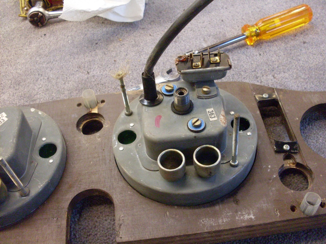
This
stabilizer is a pretty standard type used on many cars for decades
before and after the TR6. It works by putting the input voltage
across a coil of resistance wire wound around a bimetallic spring.
Current through the coil heats the spring, causing it to flex.
The spring moves a contact that disconnects the input voltage
form the coil and also from the output terminal. When
disconnected, the spring cools, eventually to the point where it again
connects the input to the coil and to the output. The result is
that the output alternates between the input voltage (which is the
system voltage) and zero volts. The higher the input voltage, the
faster the spring heats, so the faster the alternation between on and
off.
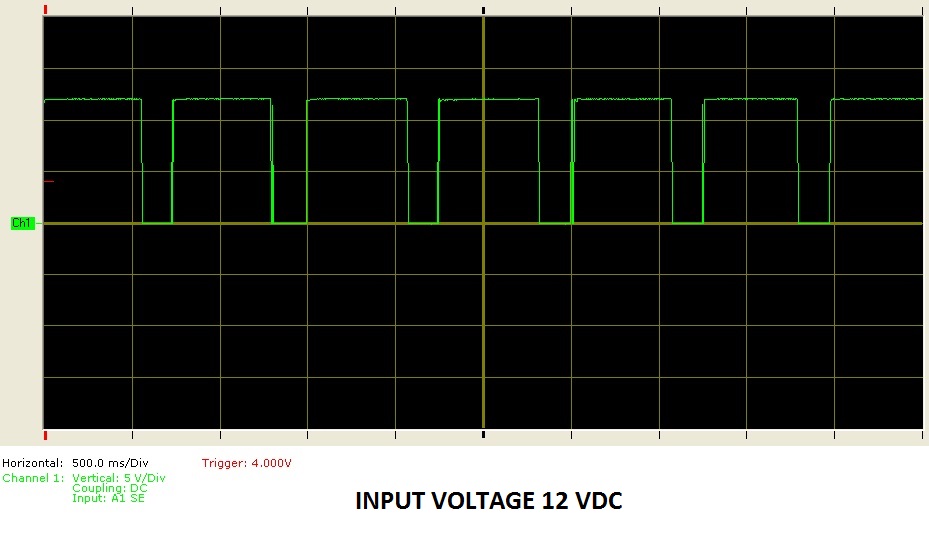
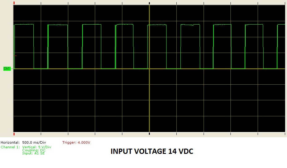
The
graphs below show what the output waveform looks like for input
voltages of 12 and 14 volts. Each graph shows five seconds worth
of time on the horizontal axis, and they show that the switching
frequency of my device was between one and two cycles per second.
Even
though it may seem a little funny to call something that does this a
"stabilizer", it does do the job. The fuel and temp gauges also
work with a resistance coil around a bimetal spring, but they are
designed to react very slowly to changes in current. They are
sluggish enough that they can't respond to the individual pulses from
the stabilizer, but settle on a reading that represents the average
current that they see. In both of the graphs above, the average
voltage coming from the stabilizer is about 10 volts. When the
input voltage is higher, the output has to spend relatively more time
at the "off" level to keep the average at 10 volts.
While
I concede that this is a tried and true approach, it is ancient
technology, pretty much unchanged since at least the thirties or
forties. Being a sort of a techie by nature, I'm not really able
to leave this Neanderthal device alone. An upgrade to a solid
state regulator is cheap, simple, and quick. There are multiple
places to buy modern drop-in replacements, and even at least one web
site that explains how to roll your own. Since this is the kind
of thing I do (did, actually) for a living, it seemed like a good place
to apply some of that expensive education.
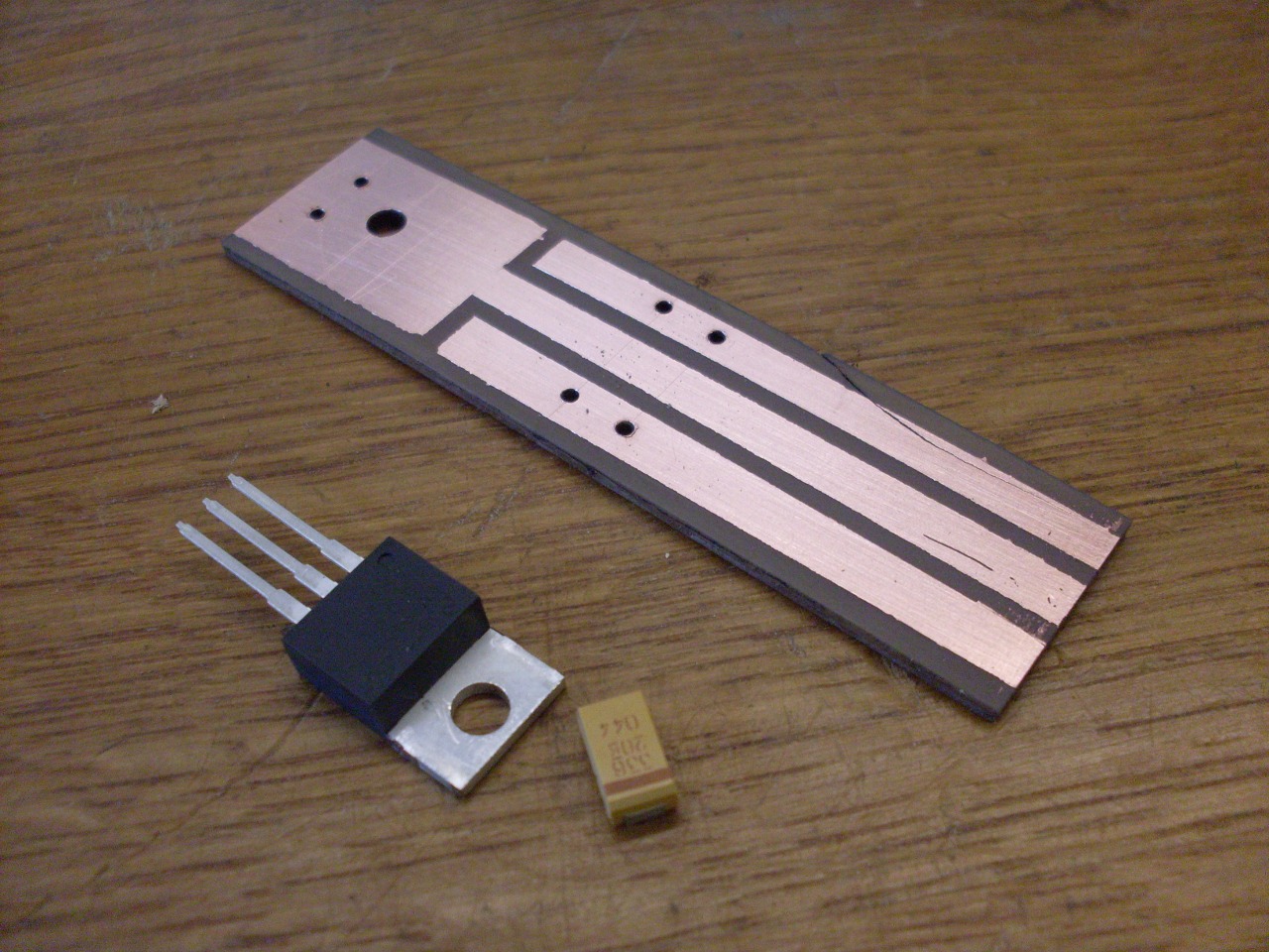
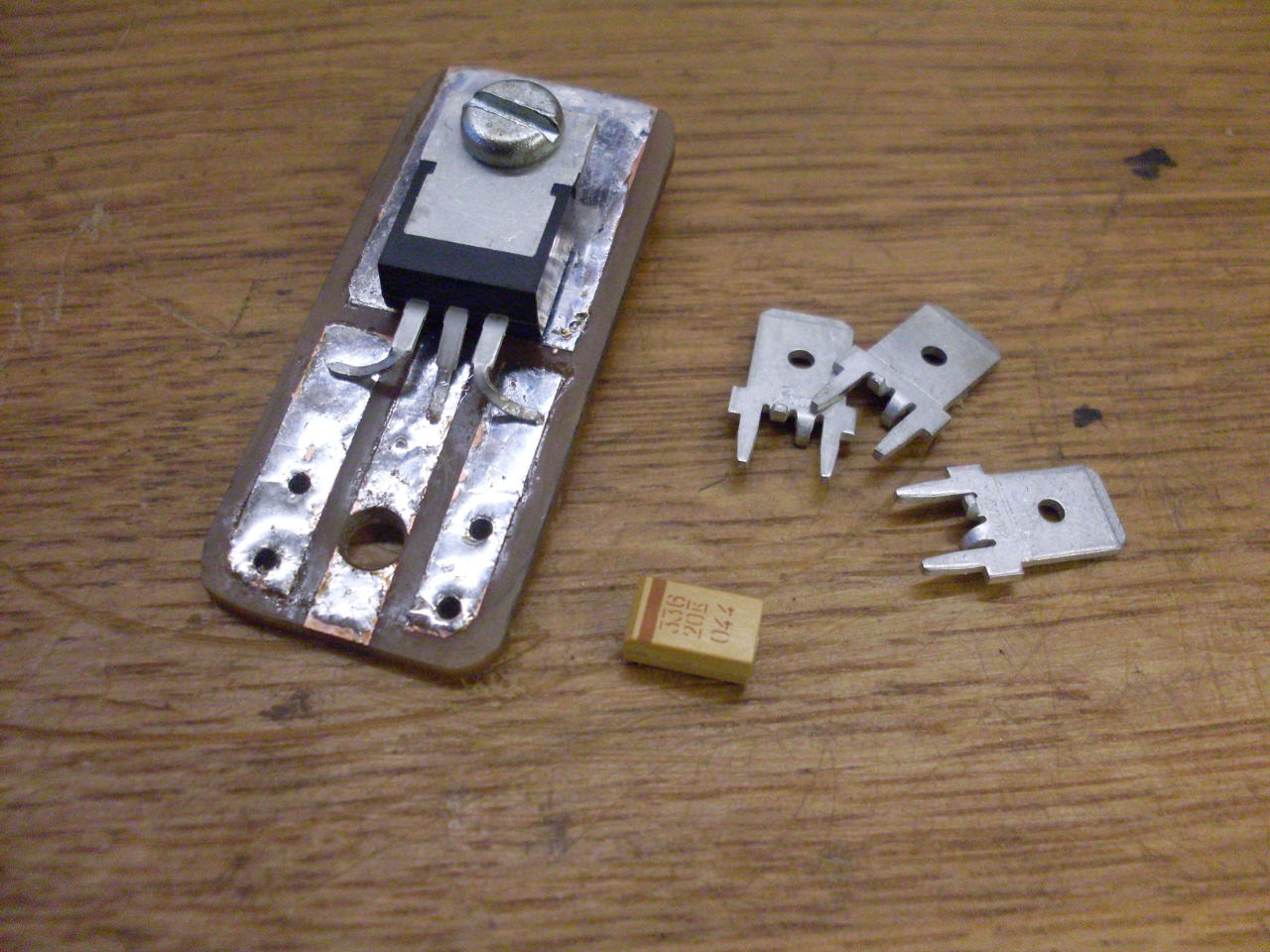
There
are a number of three-terminal voltage regulators on the market that
can be used for this application. I chose an LM2940 device
because it was the first one I came to in the catalog. The
manufacturer recommends a capacitor on the output to ensure stability.
What this means is that without the capacitor, it's possible
under certain load conditions to get some high frequency oscillation of
the output. Oscillation wouldn't affect the gauges, but it could
conceivably interfere with the radio, so I included the cap. The
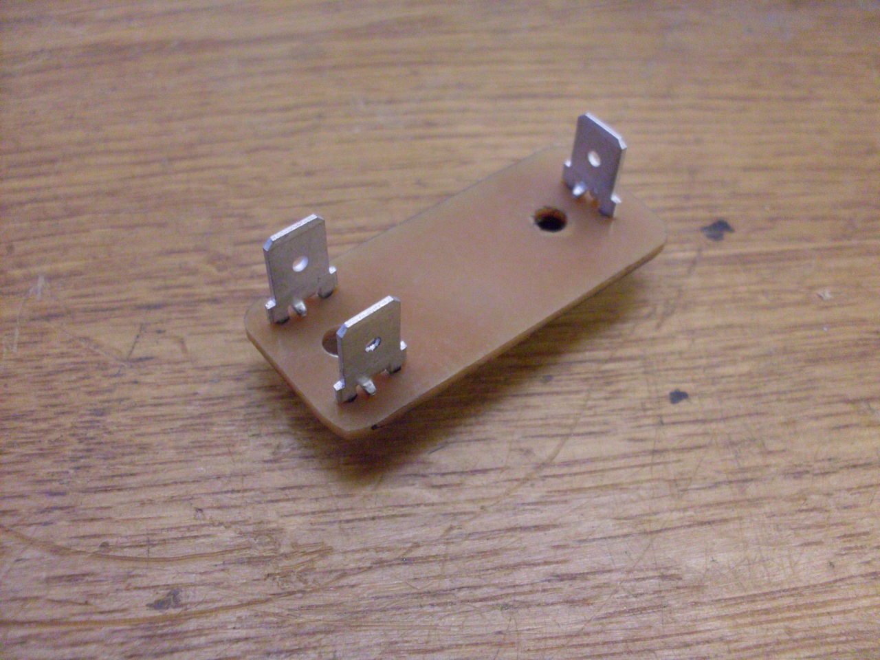
circuit board is a hand-done home brew.
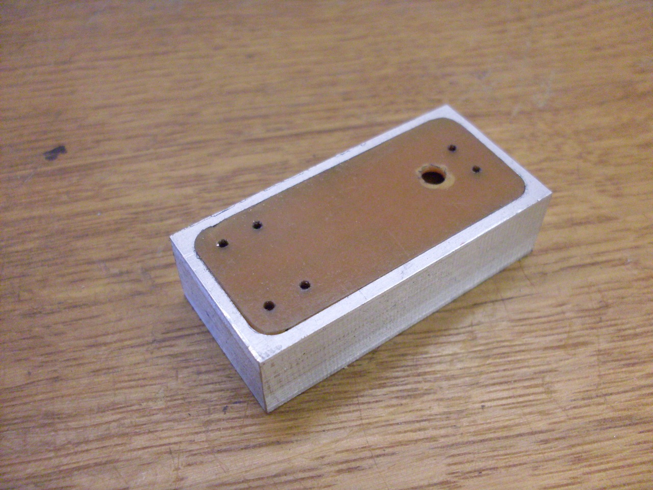
Made a little aluminum case to make mounting easier.
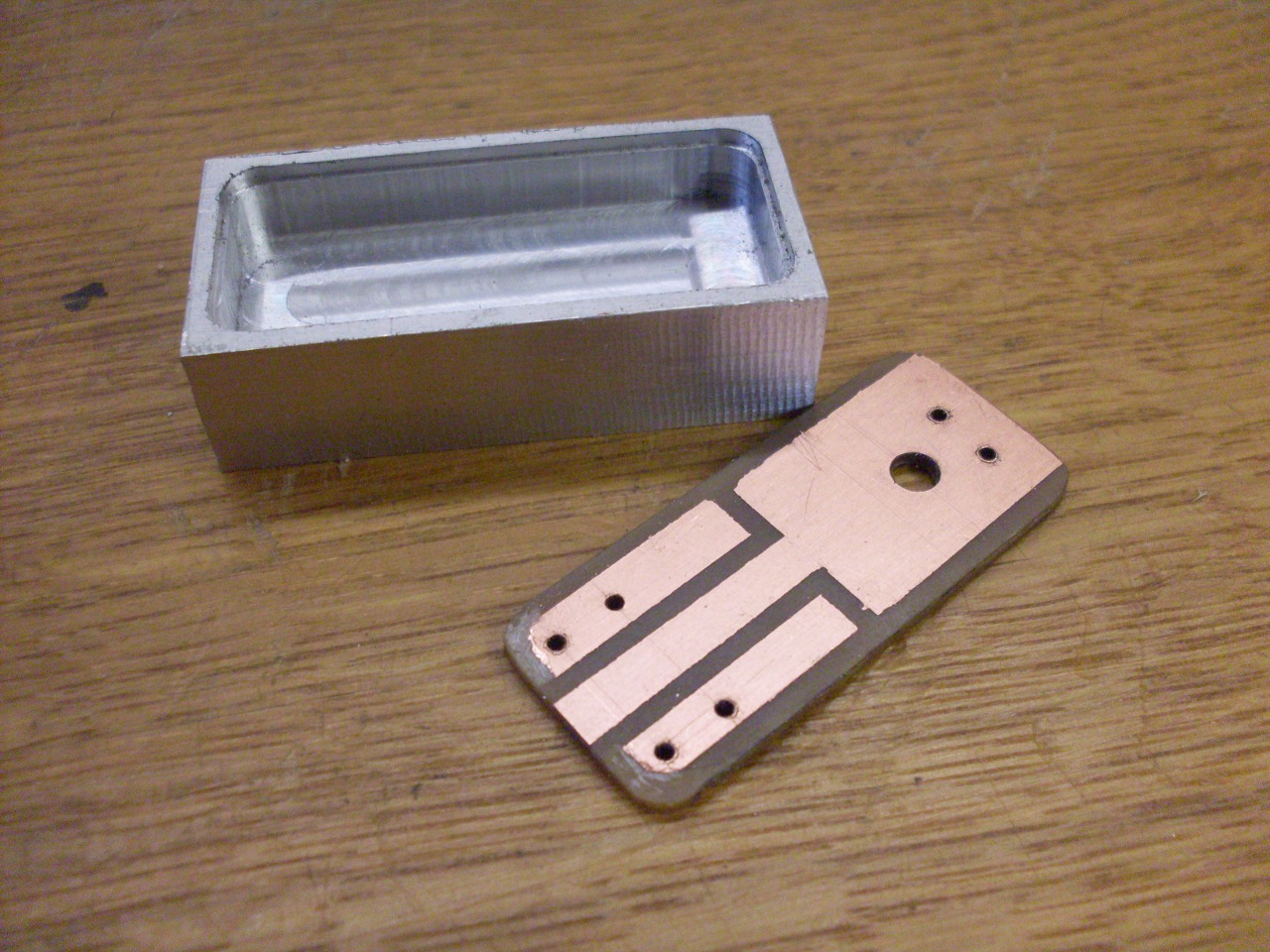
There
are only two electronic components and a few terminals. Unlike
the original device, which was grounded through its case to the case of
the speedometer, I included an explicit terminal in for ground.
Bad grounds are one of the most common causes of electrical
problems in cars, especially older ones.
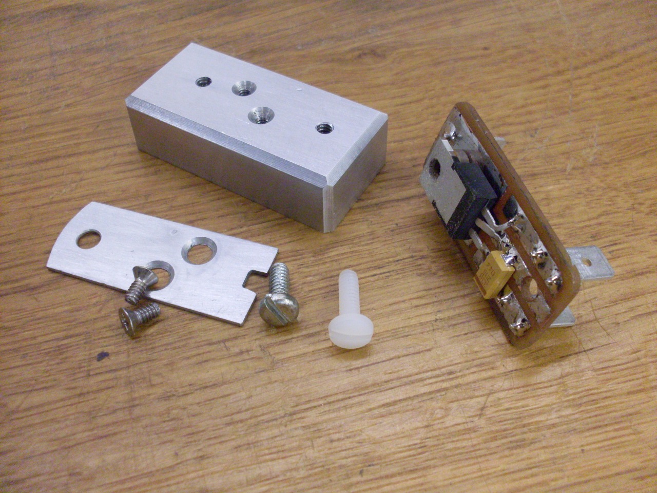
The
regulator is surface mounted on the foil side of the board.
It is facing the board so that its back side can seat against the
aluminum case for heat sinking (though at the voltages and currents
involved, heat sinking might not be necessary).
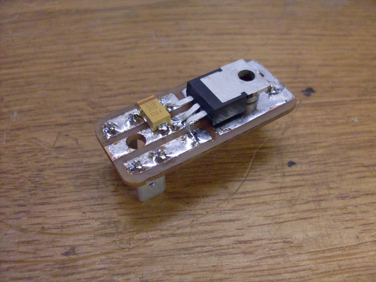
Made a bracket to match the original. I used a nylon screw on one side because of the proximity to the terminals.

The finished product.
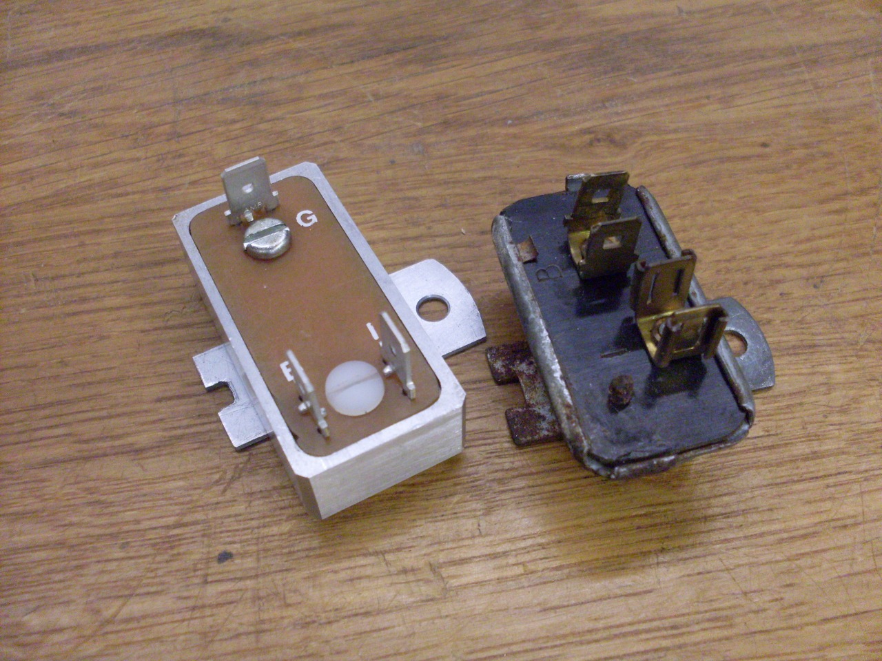

Guess I should at least test it!

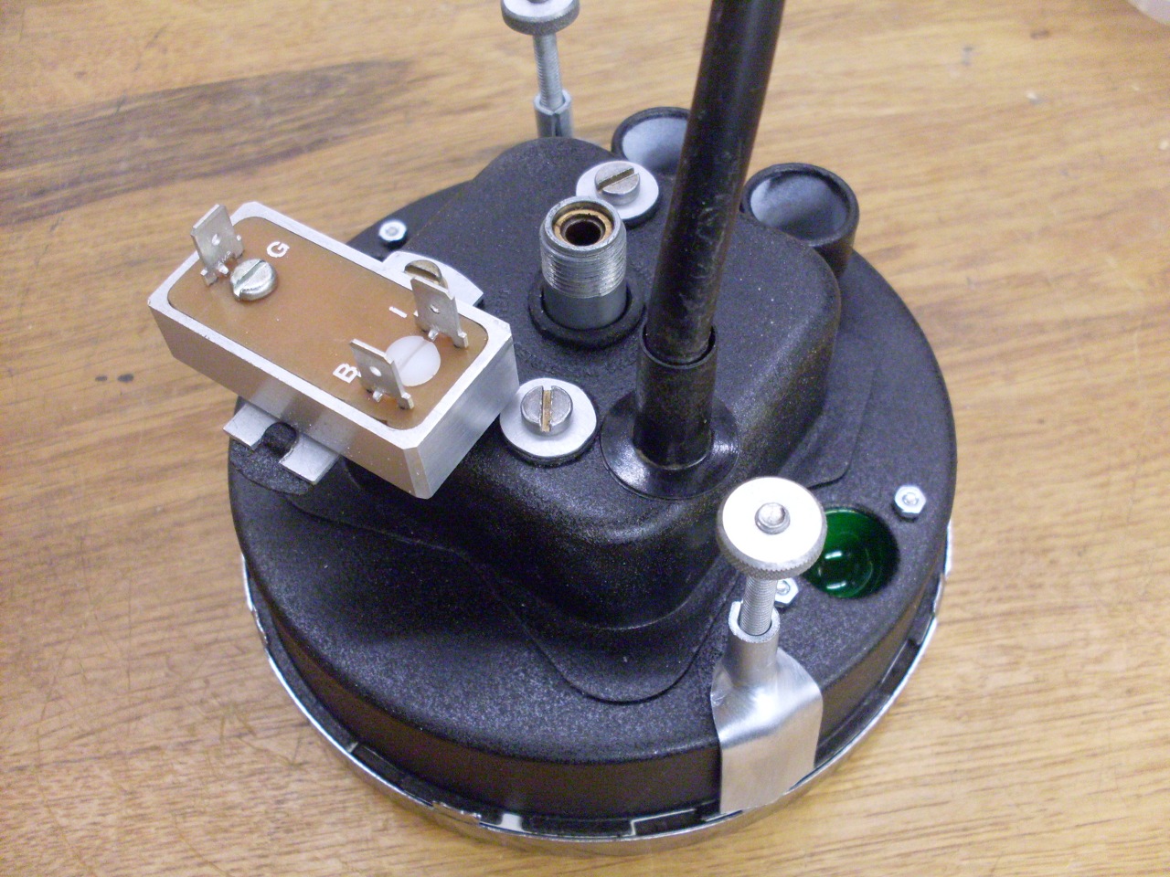
Installed it in it's new home. I keep the original for nostalgia.
So
is this an upgrade? An improvement? I don't know.
Reliability might be a little better, but I wouldn't expect to
see any noticable difference in gauge performance. I don't think
I'd pay the $15-$20 for a commercial replacement, but for about $3 in
parts and a pleasant afternoon in the shop, it seems like a good deal
to me.
Comments to: elhollin1@yahoo.com
To my other TR6 pages