November 29, 2013
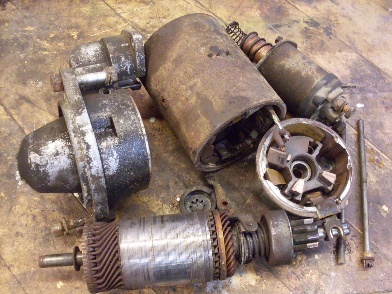
Starter Motor
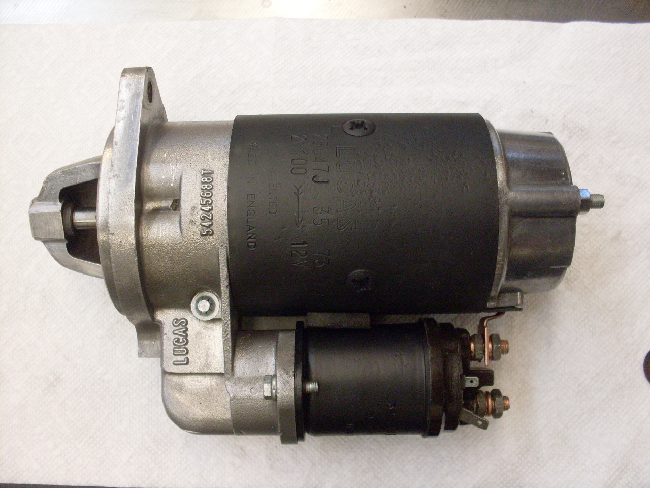
The
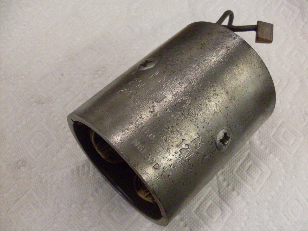
TR6s used several Lucas starter motors during their run, but mine is a
2M100 unit used on the later cars. It's a pretty ordinary design,
and the only remarkable thing that I hadn't run across before was the
face-oriented commutator. In this design the brushes are spring
loaded against the commutator, which pushes the armature up against a
thrust collar that bears against the drive gear housing. The unit
uses an external solenoid that both mechanically moves the drive
gear to mesh with the flywheel's ring gear, and also electrically
connects the motor to the battery positive. There is a one-way
roller clutch behind the drive gear that keeps the starter from being
driven from the flywheel when the engine starts.
Bushings and brushes are apparently available for these staters, but not much else in the way of replacement parts.
I
believe this starter is original, or possibly an early 80s
replacement. Its condition was nothing unexpected for a 30+ year
old unit.

Disassembly
went OK except that one of the long through bolts broke off in the
drive end casting. Damn. Have to deal with that later.

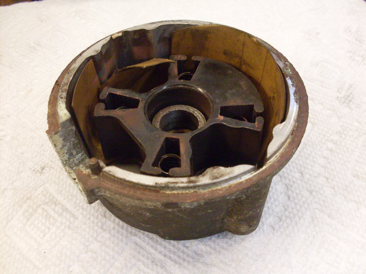
There
is a phenolic brush box in the commutator-end casting that holds the
four triangular-shaped brushes, and the springs behind them.
The brush box is riveted to the casting.
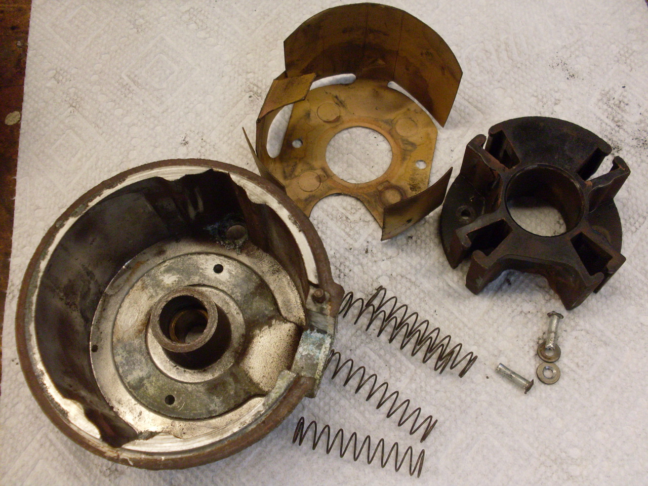
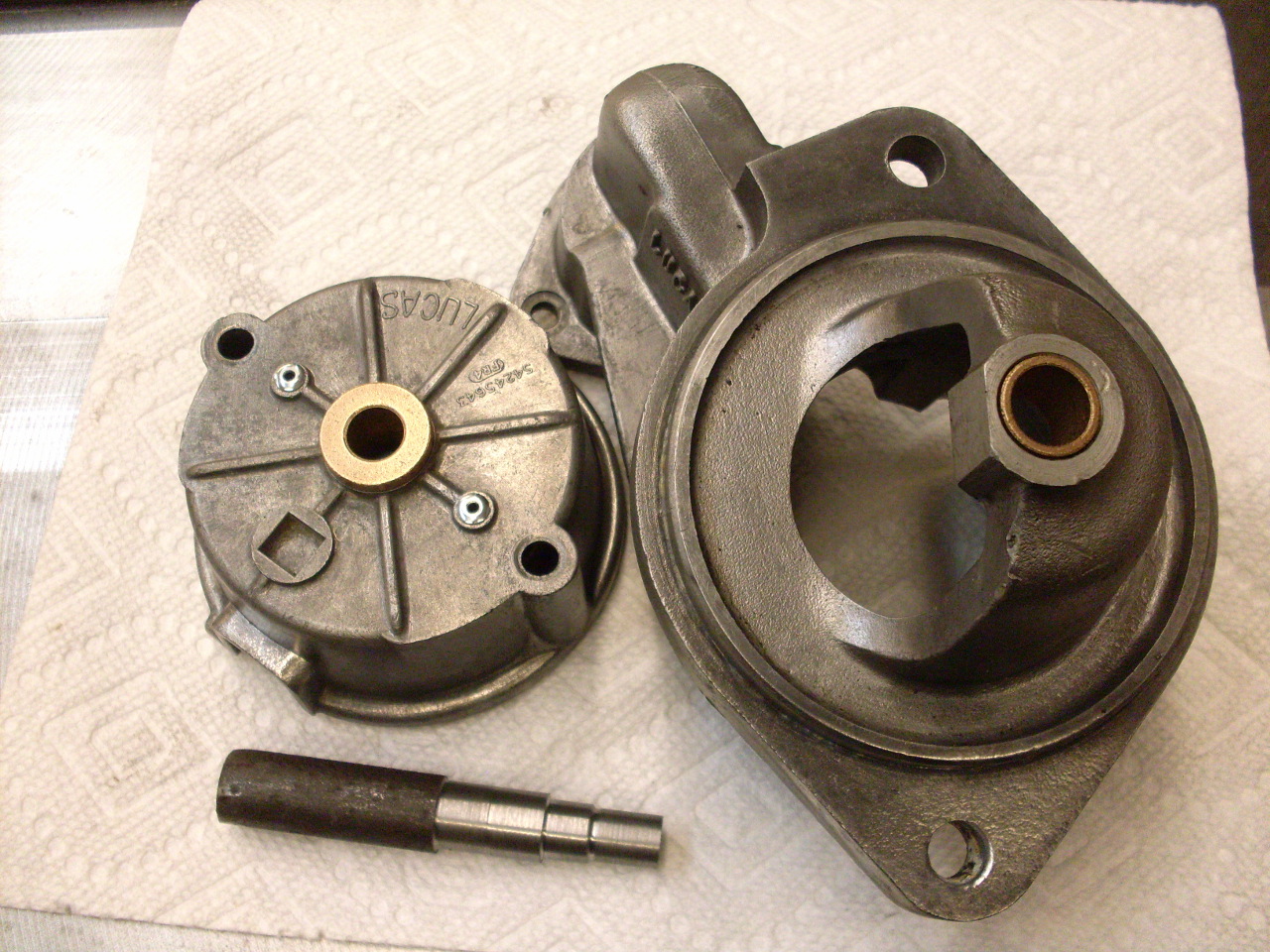
Each of the end castings has a bronze bushing for the armature shaft. A simple drift helps to drive them out.
The
yoke carries the field windings. I didn't remove the windings
themselves, but cleaned out the inside of the yoke pretty well with
compressed air. Also cleaned up all the rust and grease on the
outside.
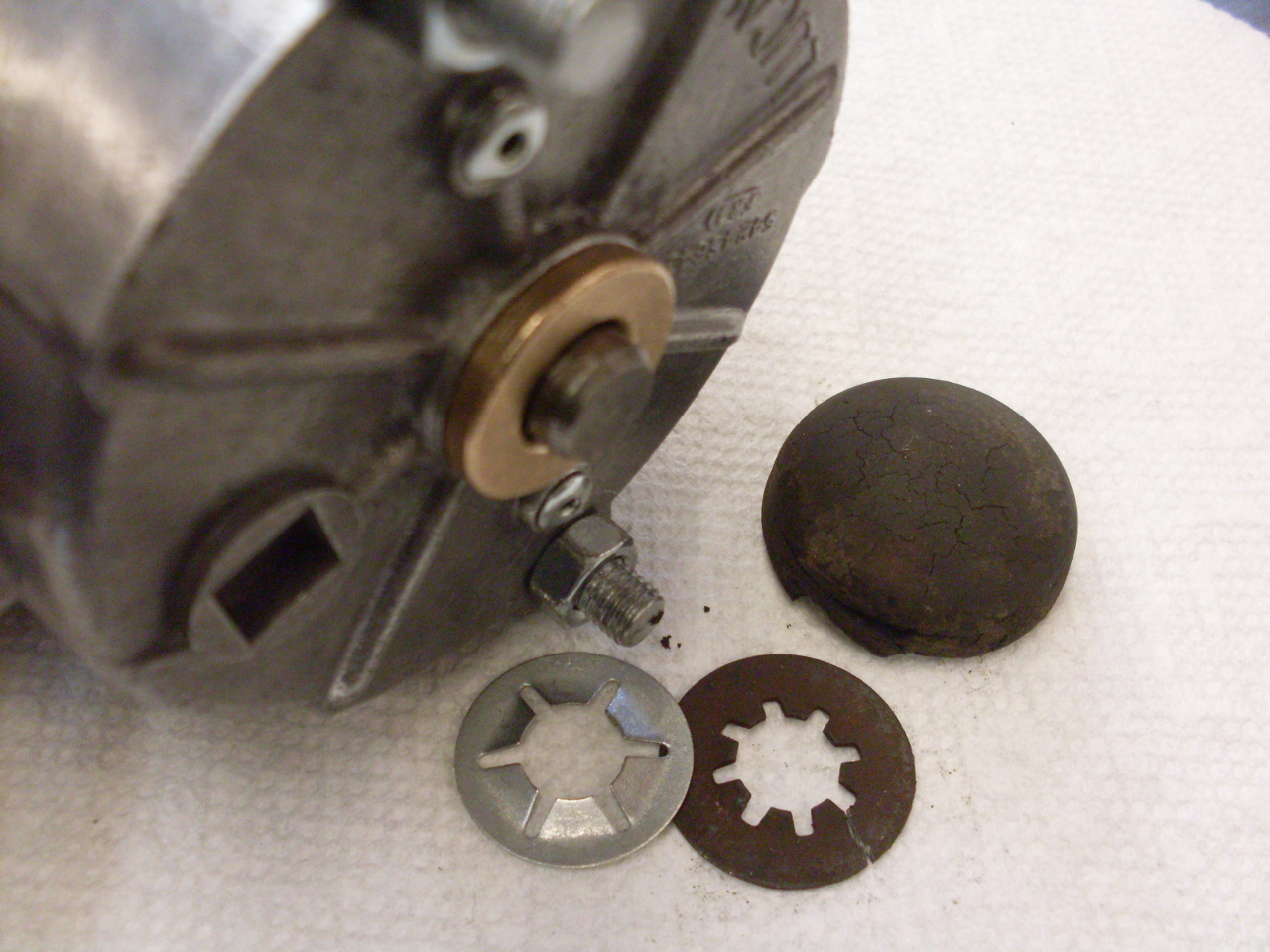
To
clean and lubricate the helical splines on the armature, the drive gear
and the roller clutch drive have to be removed from the armature shaft.
To do that, the thrust collar and "jump ring" have to come off.
That requires a simple drift tool that probably isn't available,
but isn't hard to make. Even so, it's a pissy little job that
takes way longer than it should.
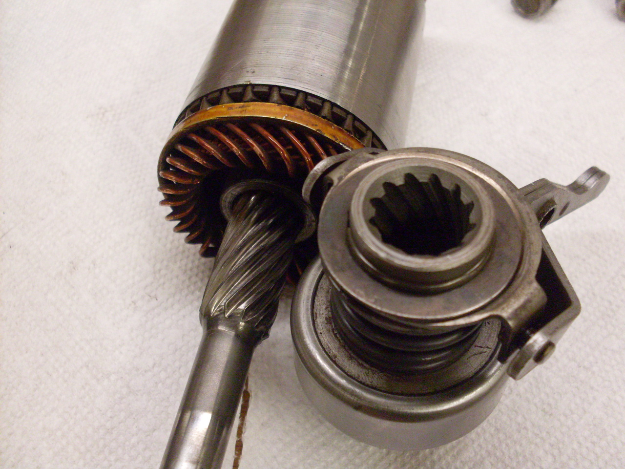
The
face commutator was in pretty good shape, and didn't require any
attention. Brush length and brush spring pressure were both well
within spec.

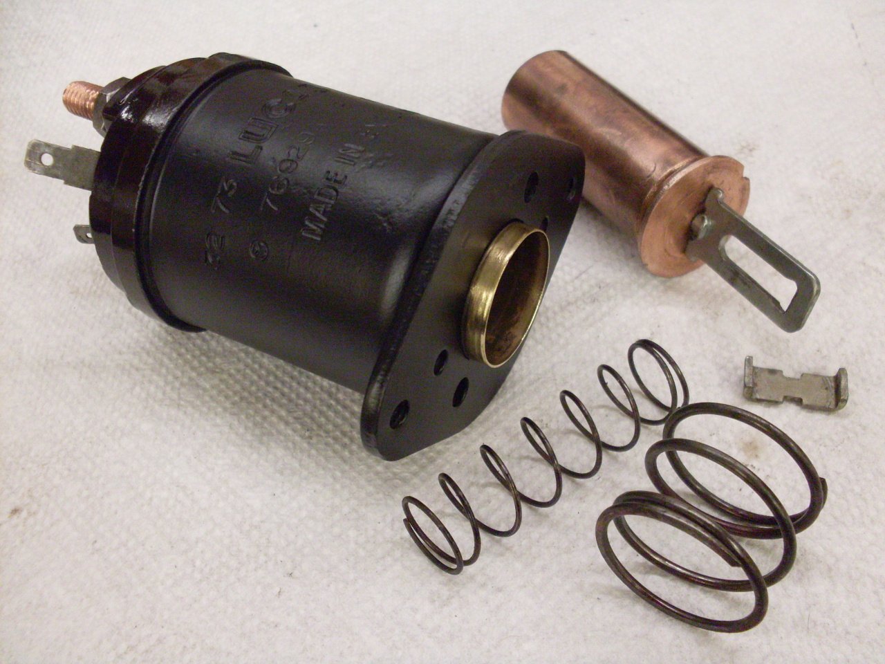
Pretty much just cleaned up the solenoid.

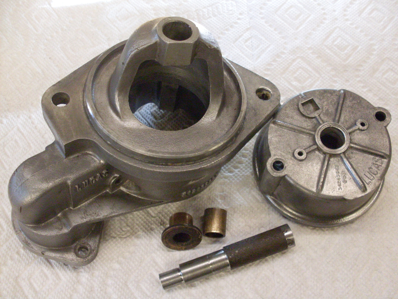
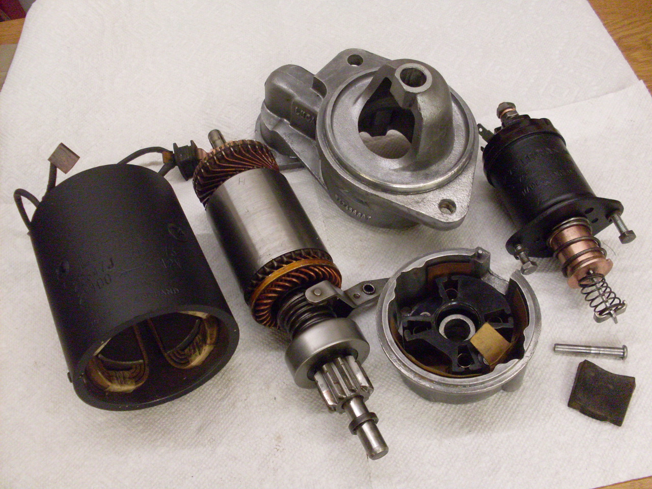
So here are all the major parts ready for reassembly. At this point, I was still waiting for the bushings.
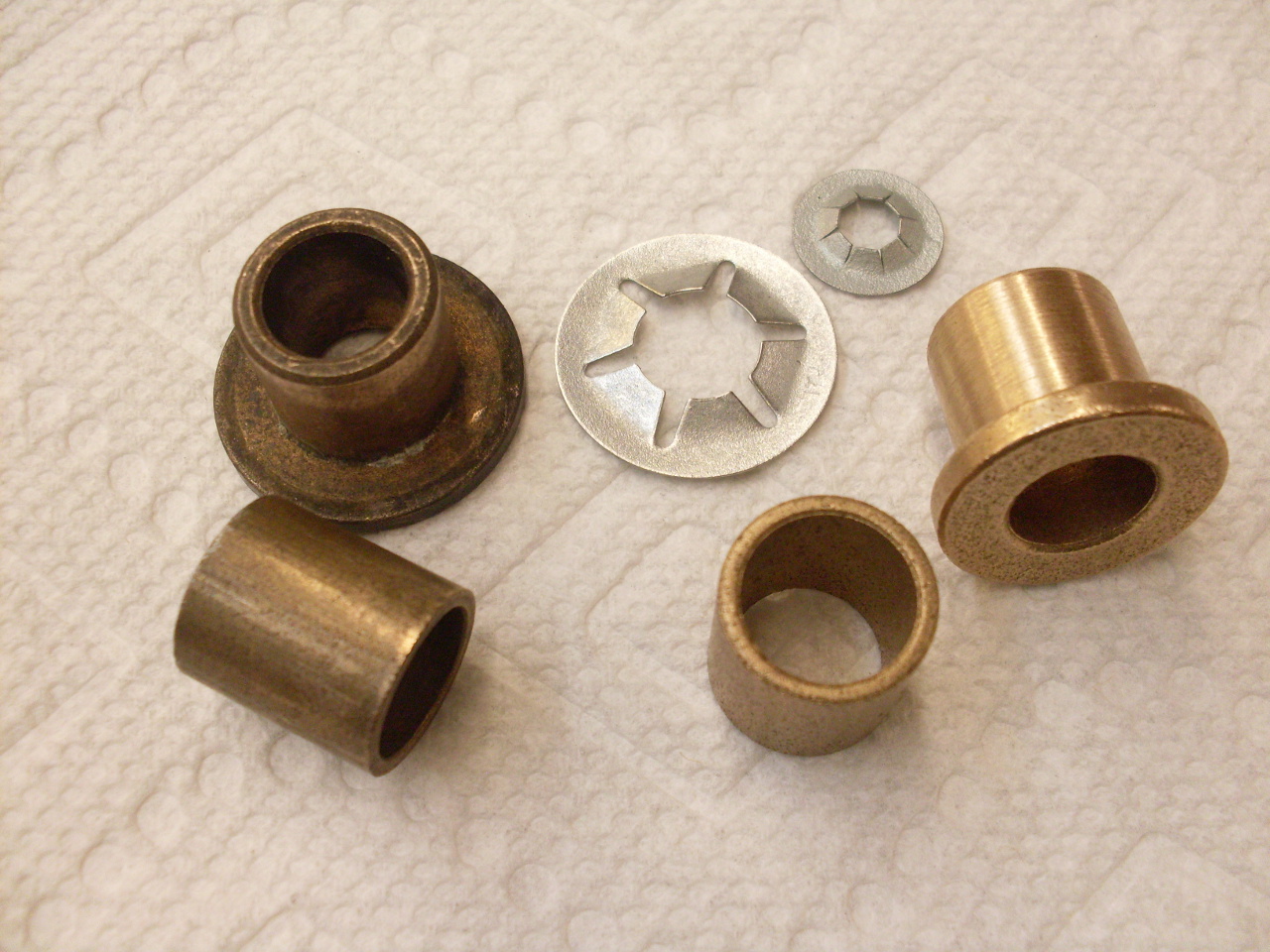
New
parts (on the right). I think these may be available from some
Triumph parts outfits, but I got them from an industrial supply place.
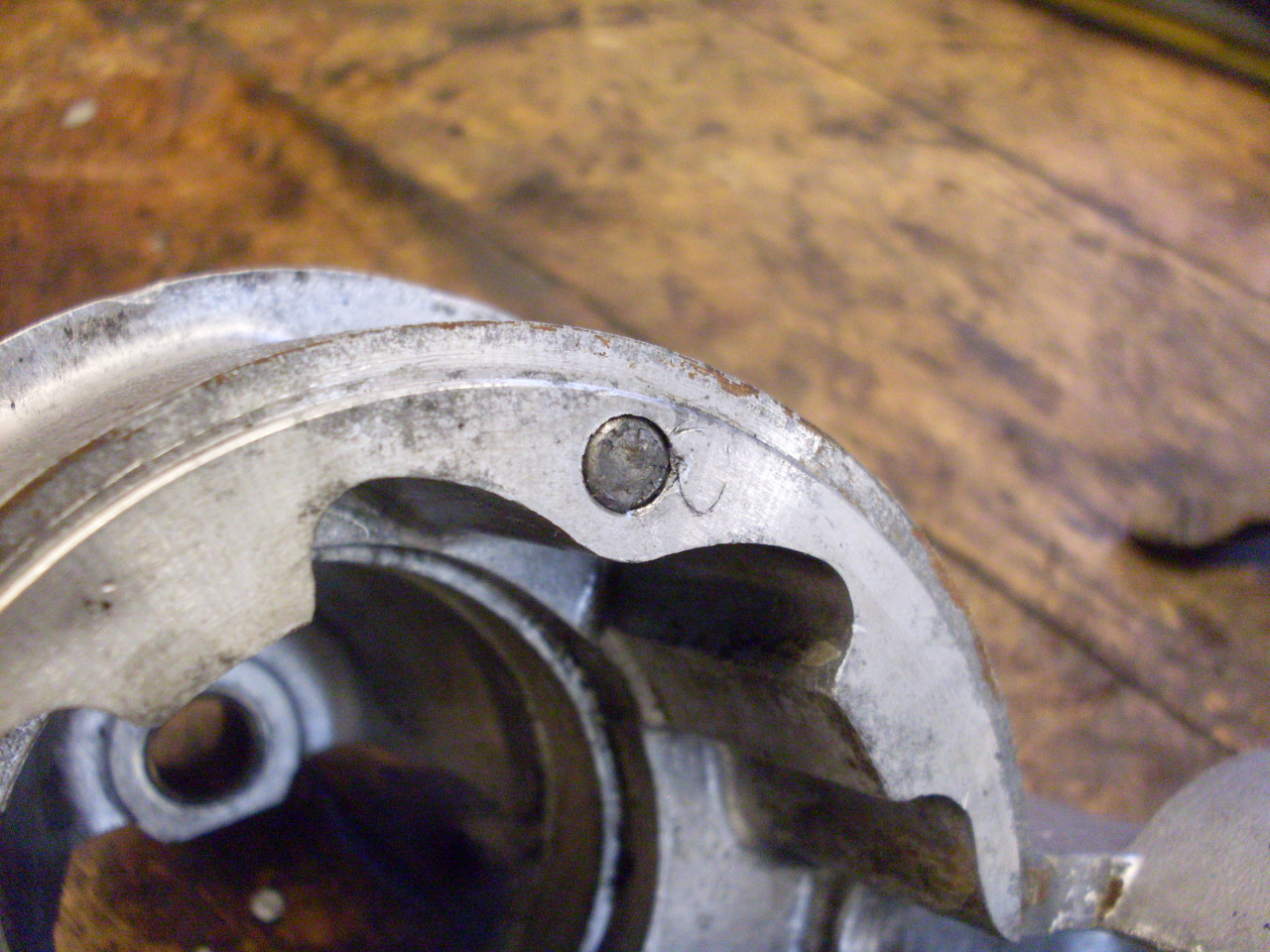
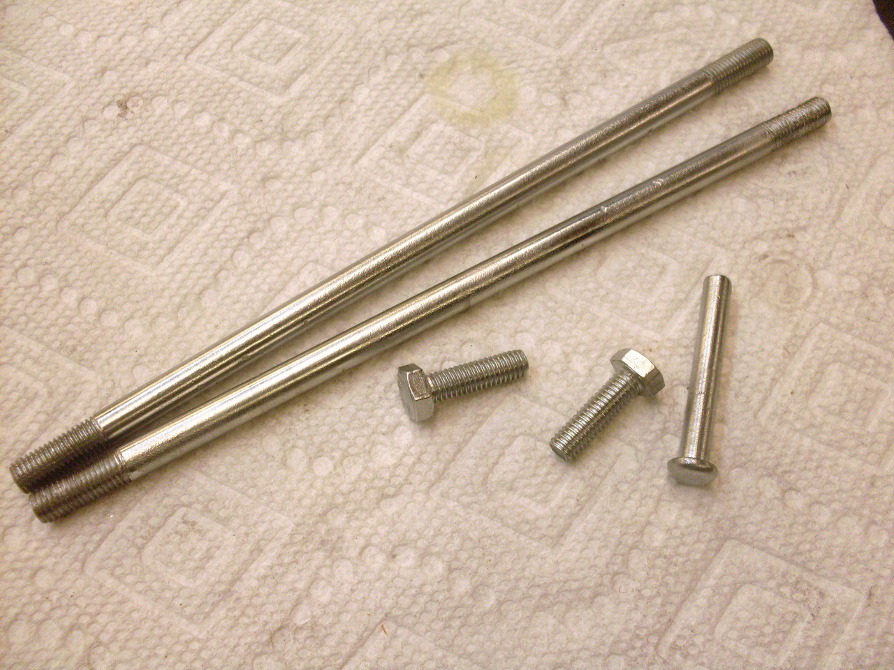
Then
there was the matter of the broken through bolt. I successfully
drilled out the remains of the old one, but wasn't able to locate
replacement parts. The bolts are 7mm metric by about seven inches
long. Even my usual industrial suppliers failed me. I might
have been able to get used ones, but judging from the difficulty I had
getting them out, it was likely that used ones would have jimmied up
straight-slot heads. I decided to make some bolts with threads
on both ends as replacements. I got some 7 mm rod, and found
that I already had a 7mm x 1.0 threading die. I've had that
metric tap and die set for probably 30 years, and I'm pretty sure this
is the first time I've needed the M7 x 1.0 die.
I
also have been fooling around with home zinc plating recently, so I
plated the bolts and also the solenoid bolts and the solenoid pivot pin.
The new "spire nut" ("push nut" on this side of the pond) on the solenoid pivot pin.
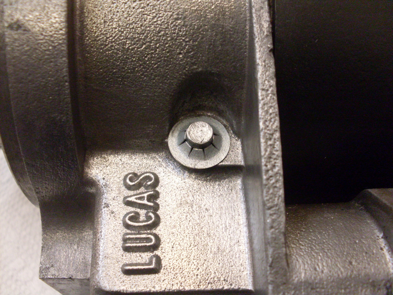
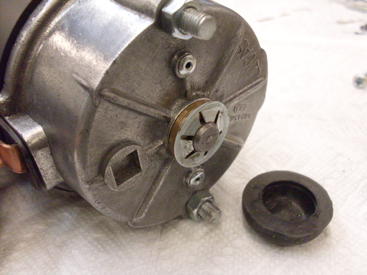
The
only thing lacking is the rubber cover for the end of the armature
shaft. Originally, it was held on by gripping the spire nut.
The new spire nut has a smaller OD, which is actually moot right
now, since the cover is too rotted to grip anything anyway.
Still working on what to do for this.
Final
assembly goes on the shelf for eventual installation. I guess I
should test it first. Total cost for this rebuild was under $10,
plus a few hours time.
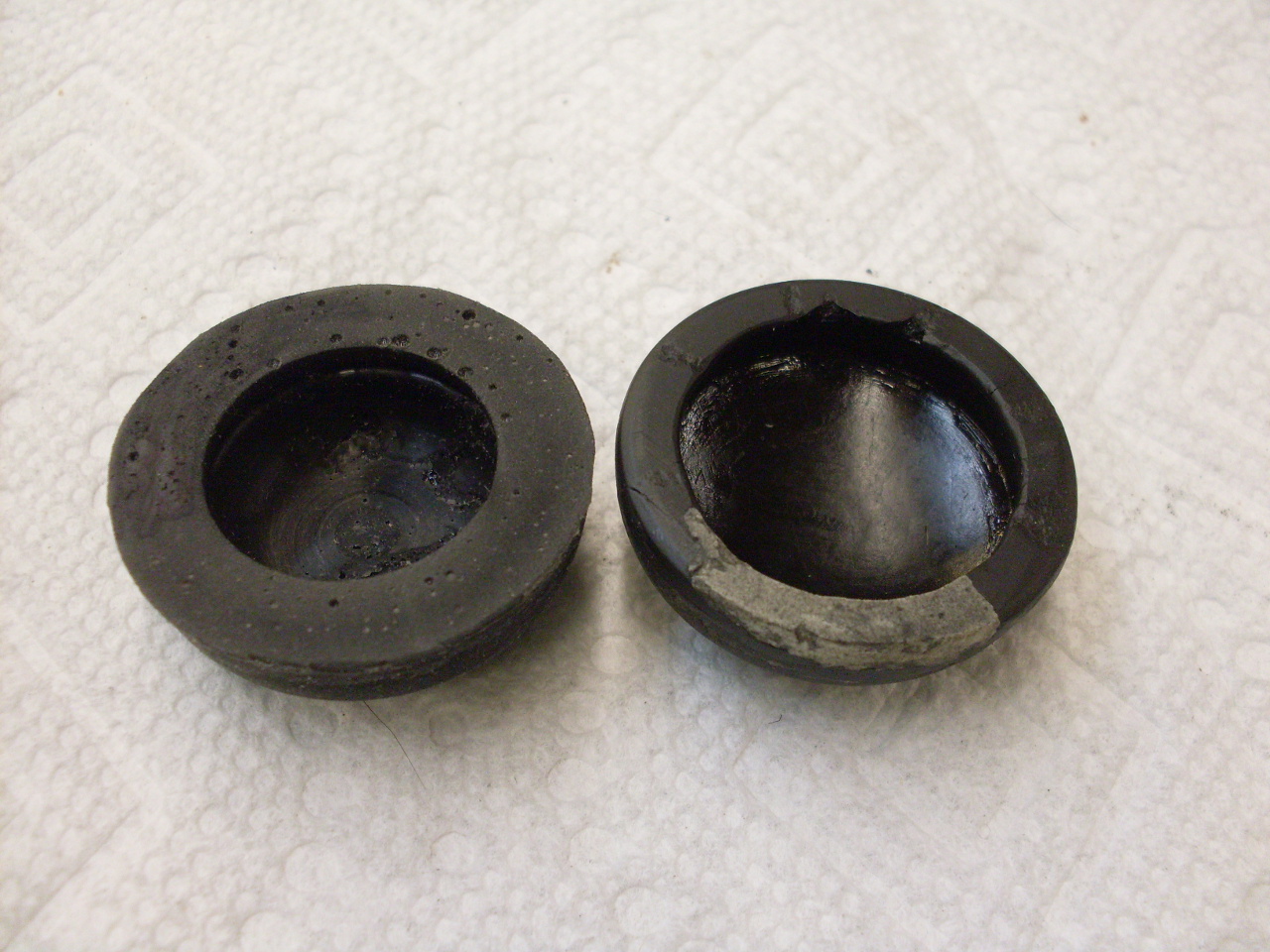
Update, December 3--
I
wasn't successful in finding a rubber cap for the end of the armature
shaft, so I resorted to casting one. Here is the cast rubber part
(on the left in each pic) compared to the old one. The thicker
wall on the new one was necessary because the new spire nut was smaller
in diameter than the original.
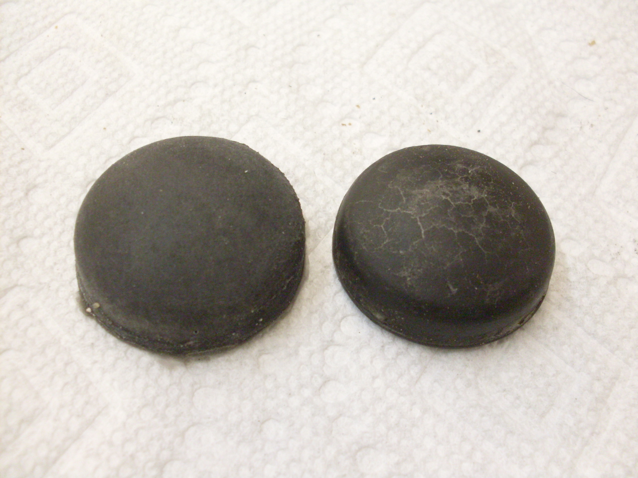
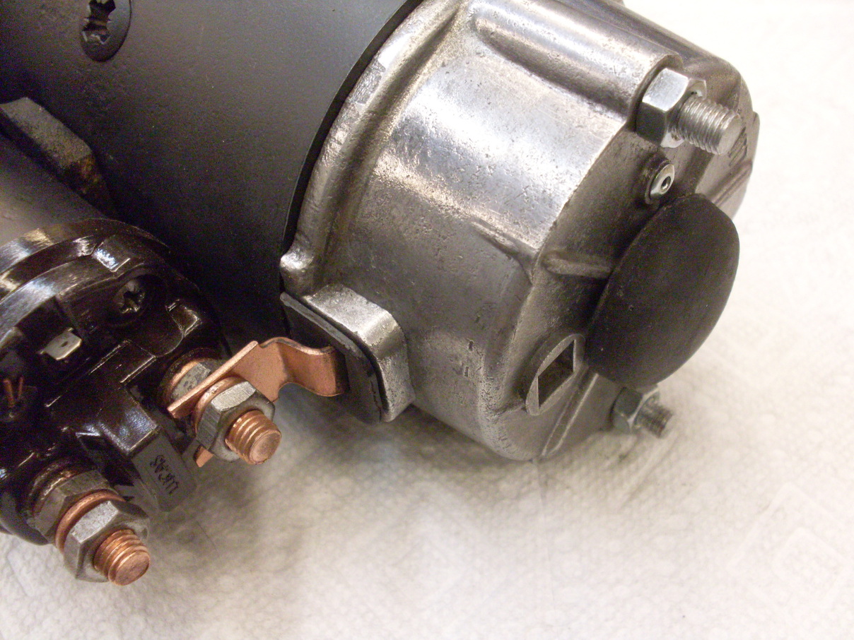
Here is the new part installed.
For those really interested in the casting details, go here.
Other Pages
Comments to: elhollin1@yahoo.com