To my other
TR6 pages
January 12th, 2015
Gauges
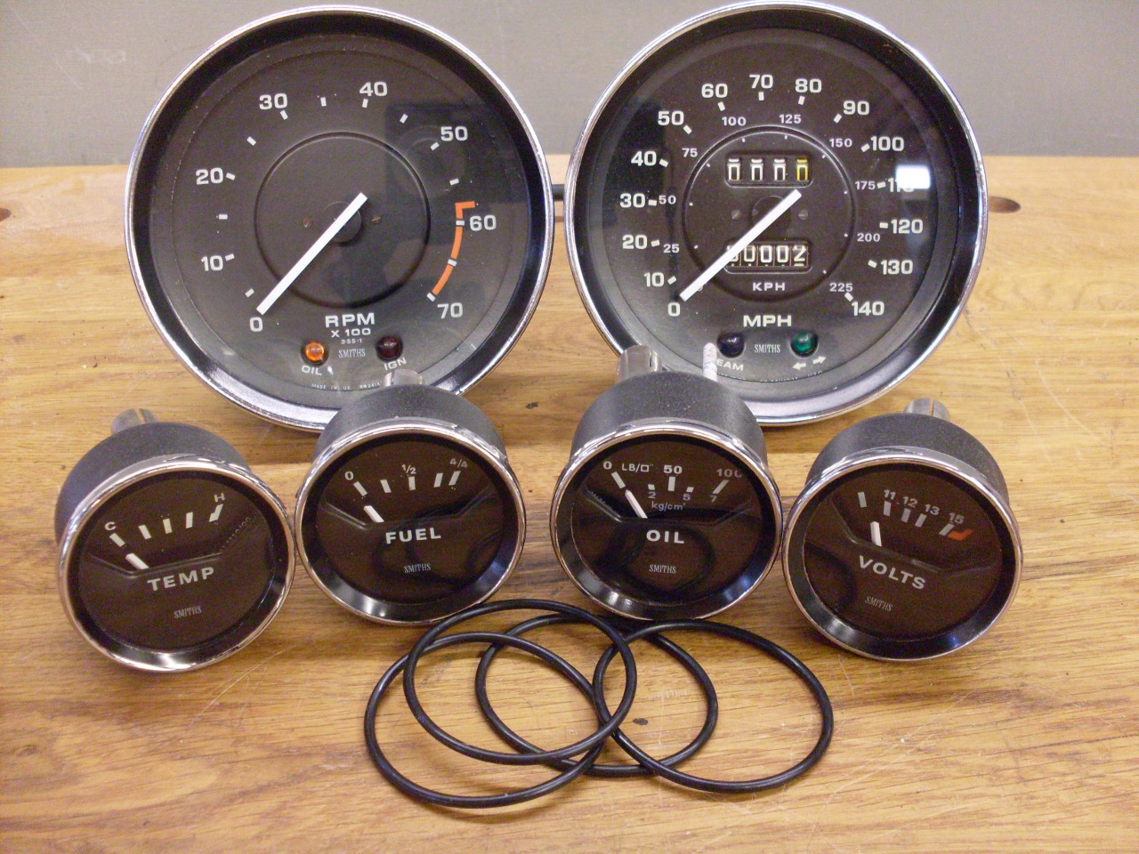
Besides
the speedometer and tachometer, the TR6 of this year had a complement
of four gauges: fuel level, coolant termperature, system
voltage,
and oil pressure. The first three are electrically operated
while
the oil pressure gauge is mechanical. The three electrical gauges are
mechanically identical inside, and only differ in their scales and
labeling.
I'll describe what I did to the voltmeter here, and just say
that
the others were the same.
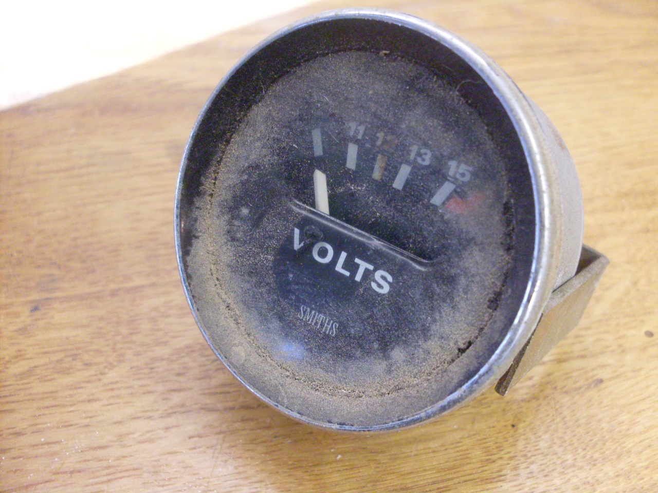
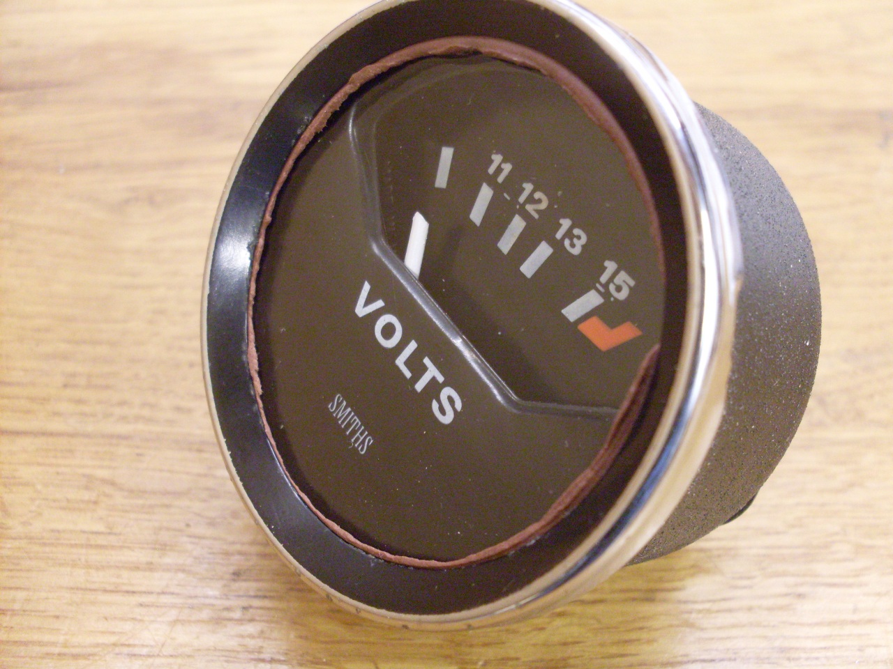
All the gauges were dirty and crusty, but apparently intact and
undamaged. I had no idea if they worked or not.
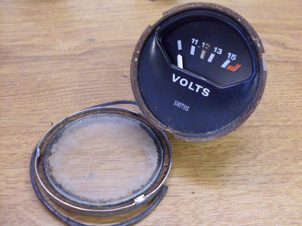
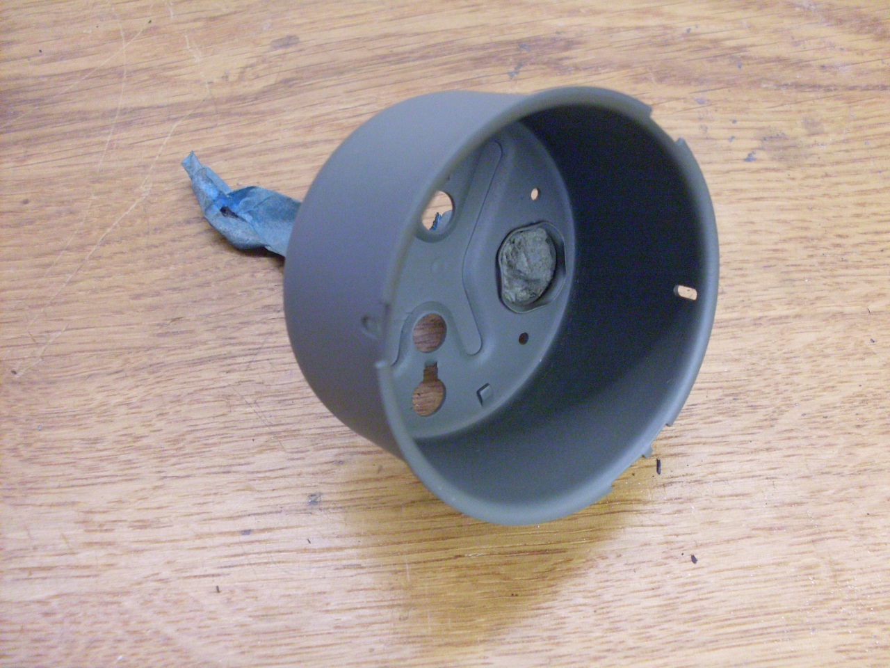
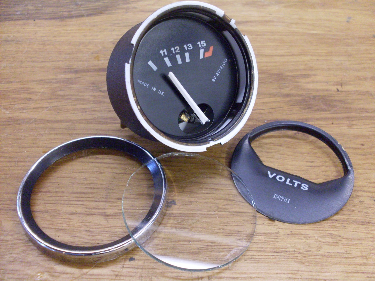
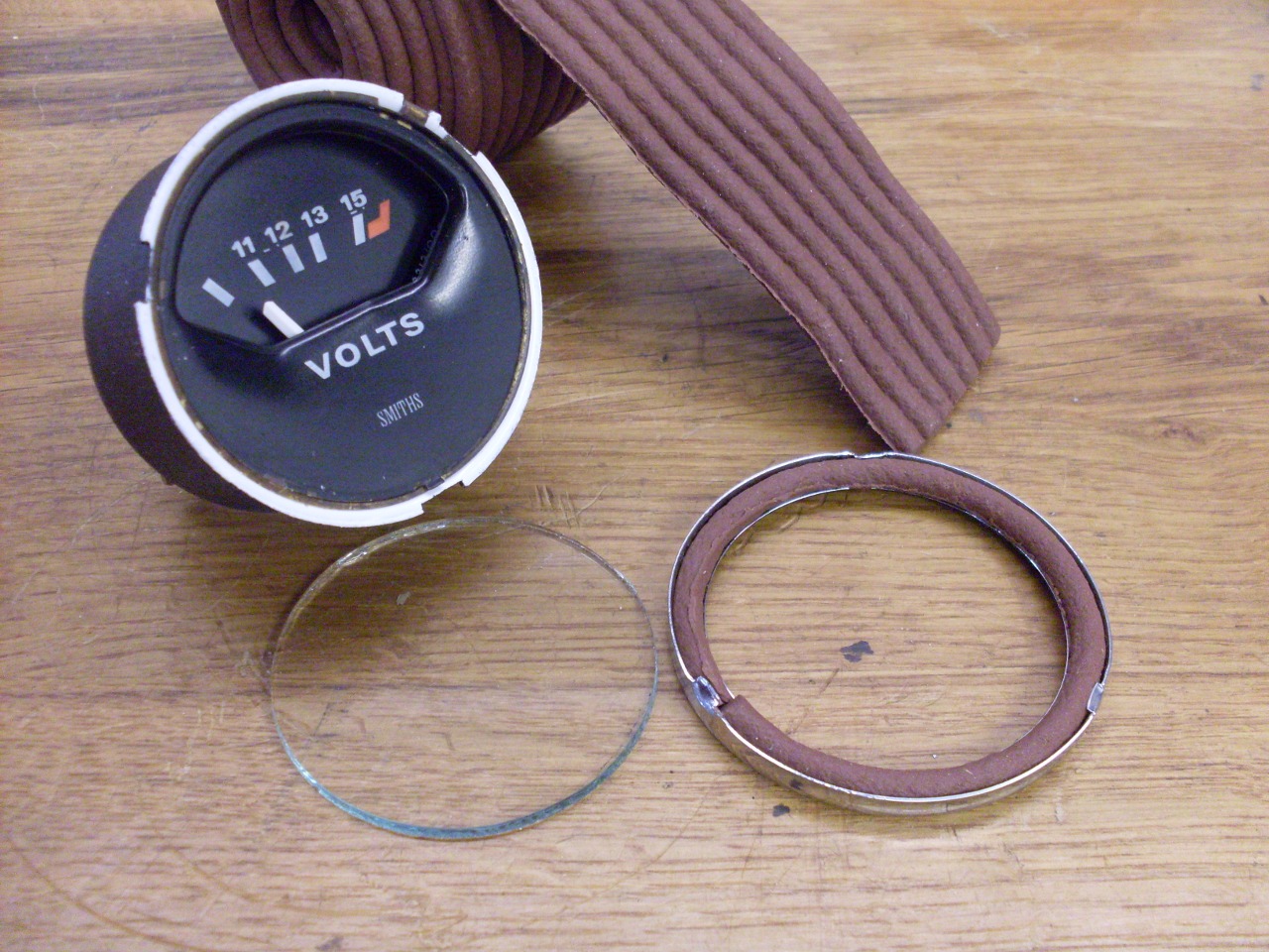
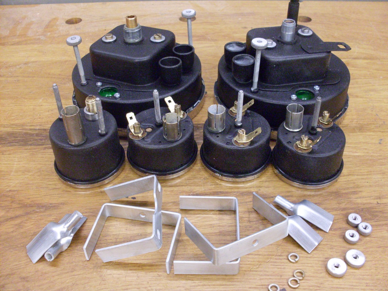
The
front bezels come off by twisting them, bayonet style, until they
release. Smiths used some kind of sealant between the bezel
and
glass that had long since petrified.
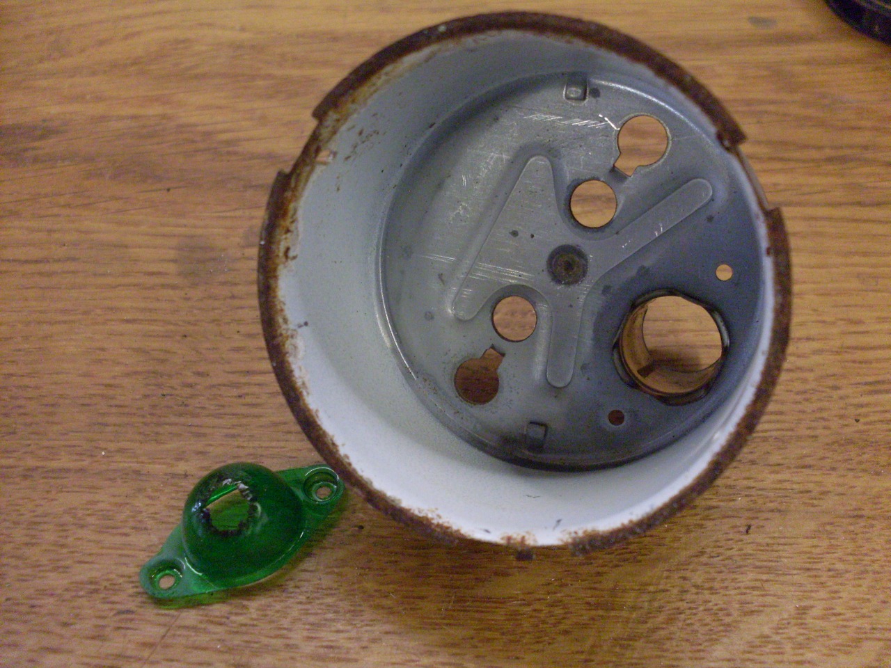
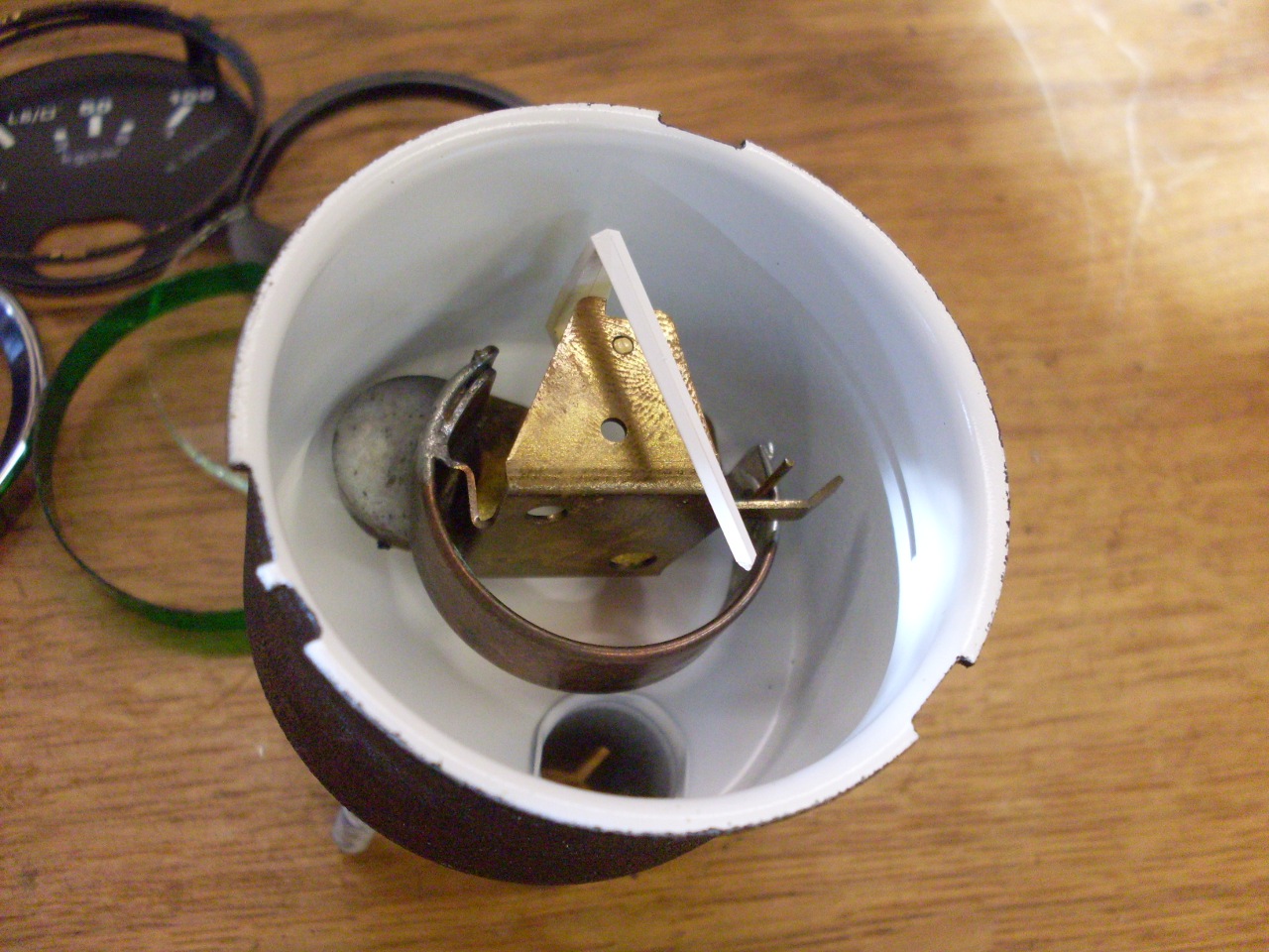
The
innards are released by removing the two barrel nuts on the back of the
body. This reveals the actual meter movement. It
also
revealed that the colored plastic lens for the gauge illumination bulb
had been fried. This was the case in all of the gauges.

I worked on the cases first. I removed the toasted lenses.
There isn't much hope of finding good replacement for these,
but I wanted to preserve the green illumination for the gauges.
I looked into a few alternatives. One was to use
LED bulbs. These can be had in many of the popular bulb
sizes, and they come in a range of colors. Dimming can be an
issue with LEDs, and even for those that claim to be dimmable, it
typically can't be done with a rheostat based dimmer that the
incandescents use. Even with a proper dimmer suitable for
LEDs, the dimming action is often different than for incandescents,
especially at low levels of illumination.
I also considered making lenses from green colored film. I
had some film, but didn't get very far on this idea.
Another option was to convert the electrical gauges to use the
filtering suystem used on the oil pressure gauge. The oil
gauge uses a strip of green plastic to cover the openings in the side
of the dial. These openings are how the light from the bulb
in the case gets to the dial. I think this would have worked.
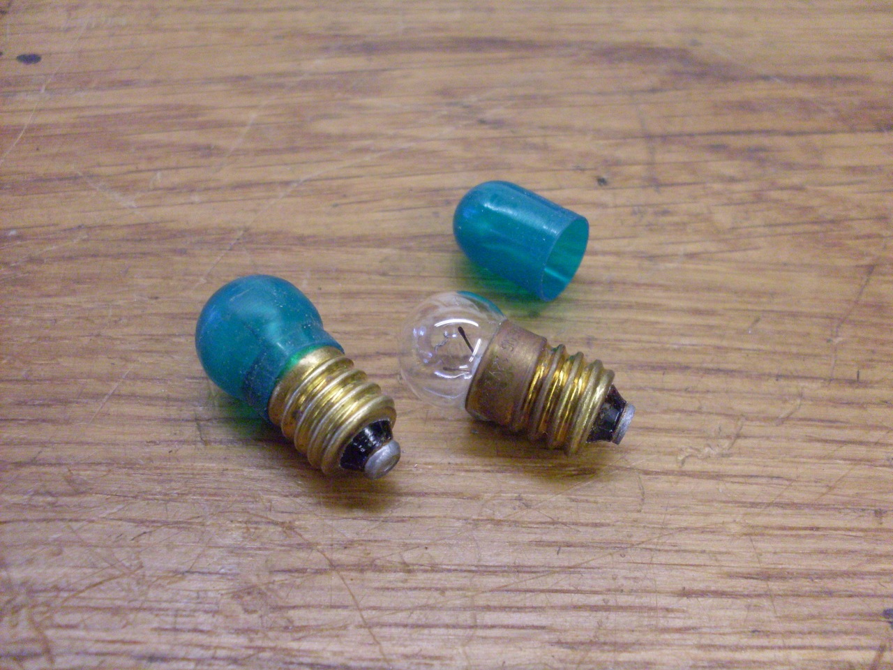
The solution I finally landed on was to use little green covers for the
bulbs. These covers are made for this purpose, and I bought
them from a supplier of gauges and gauge accessories.
The cases were blasted, dipped, primed, and painted.

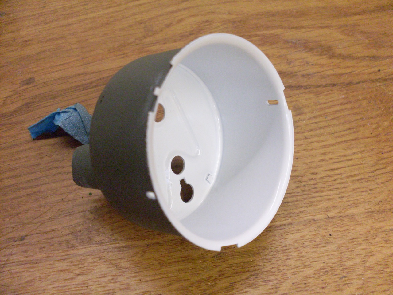
The dials were dirty and had some stubborn smudges on them.

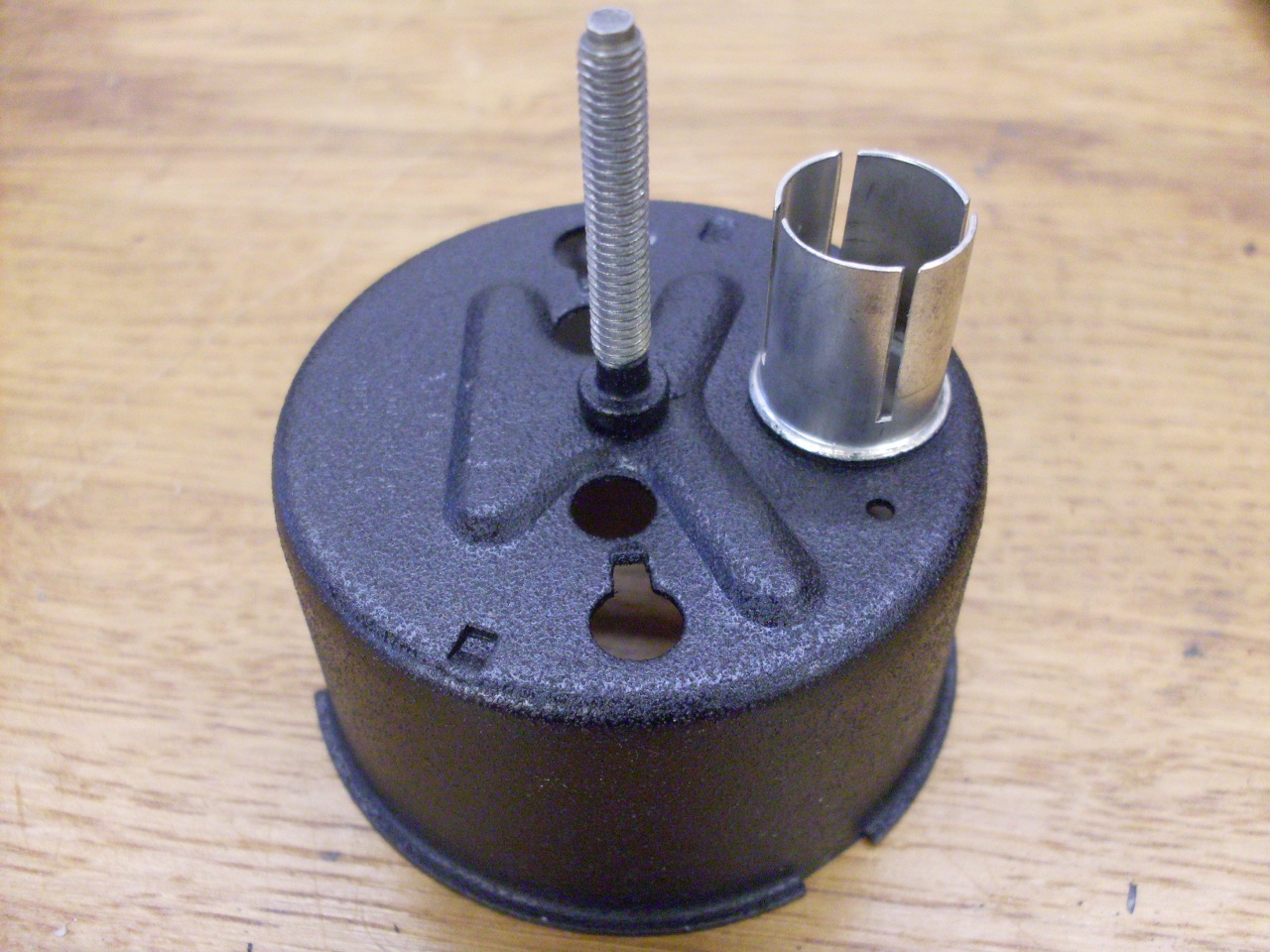
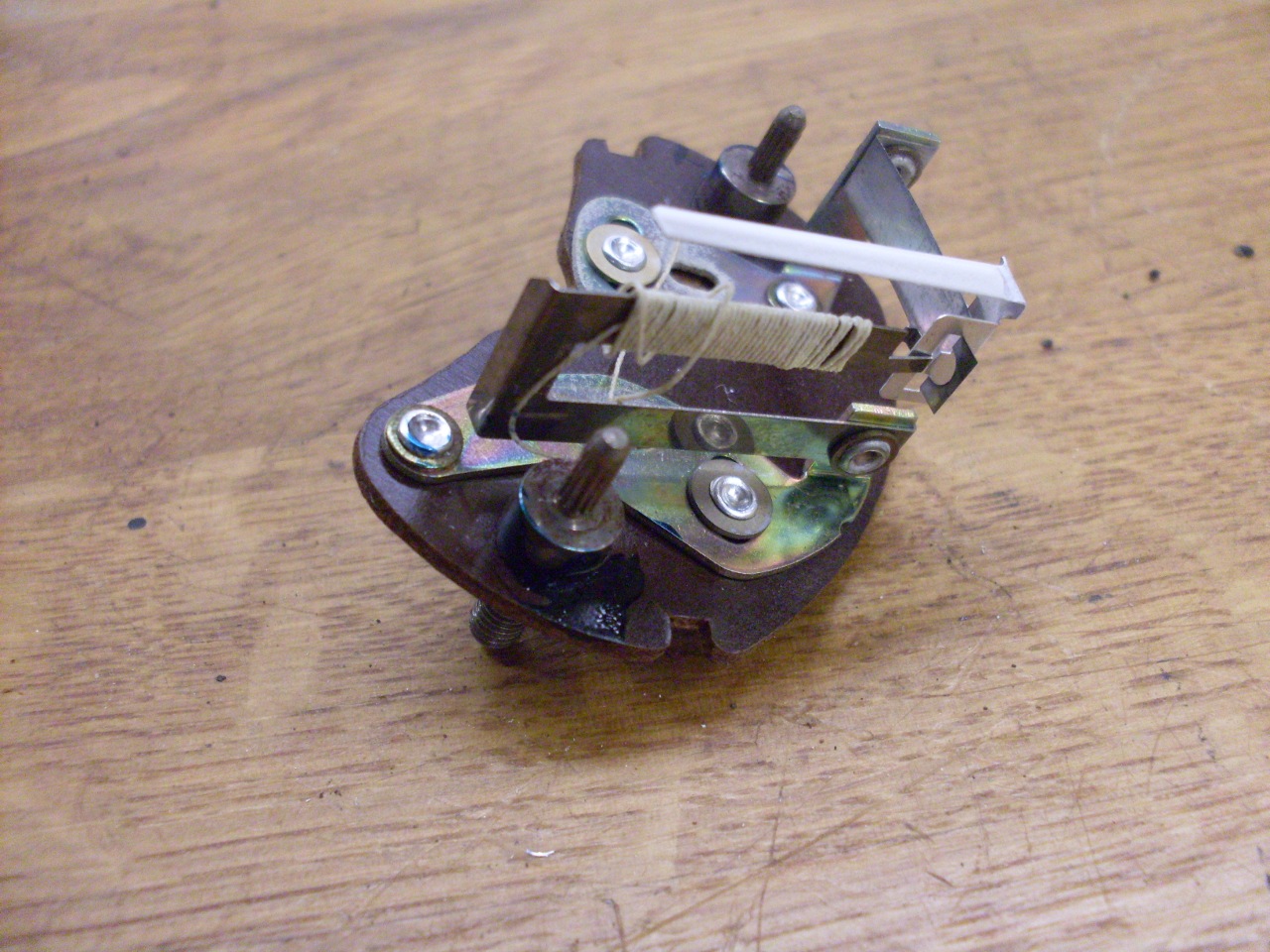
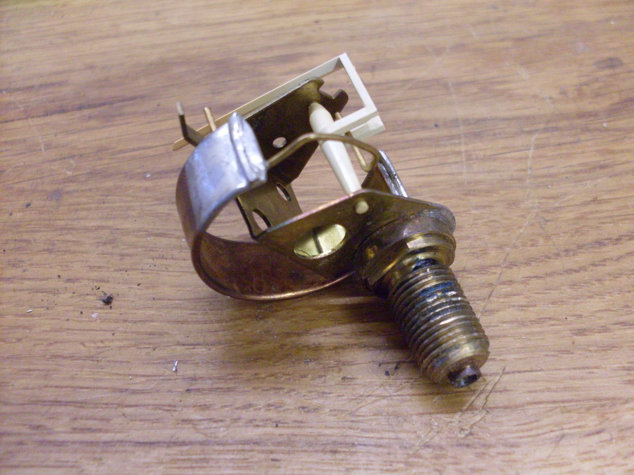
Then I turned to the innards. A quick check to see if the
movement is working.
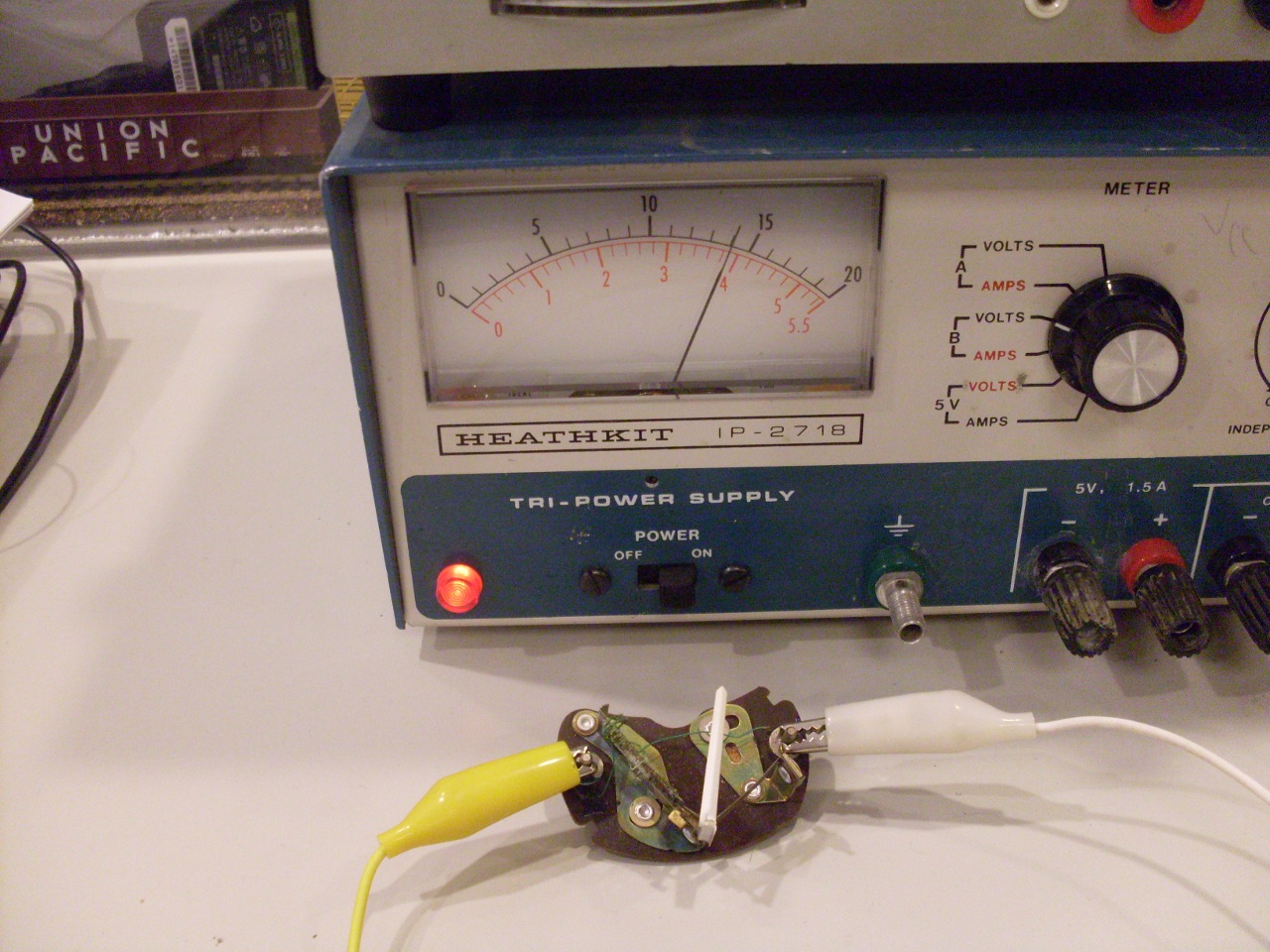
These
meter movements are not like those found in many test instruments.
These work by sending the current to be measured through a
small
coil of resistance wire, where it heats a bimetal spring,
and spring bends as it gets warmer. This bending is
translated into motion of the pointer. This design is
relatively rugged and cheap, but not all that precise or accurate.
It also implies a scale that is non linear, but the main
feature if this thermal approach is that it is very slow to react.
It can take tens of seconds for the pointer to reach a final
position. This may not be a big deal for the fuel gauge or
even the temp gauge, but consider a situation where an intermittent
short in the electrical system causes a voltage drop large
enough to make the lights dim and the engine miss. The slow
voltmeter will ignore this and continue to show a rock steady normal
reading. This is why many people consider these guages not
much better than idiot lights. The temp gauge doesn't even
have numerical markings on the dial.
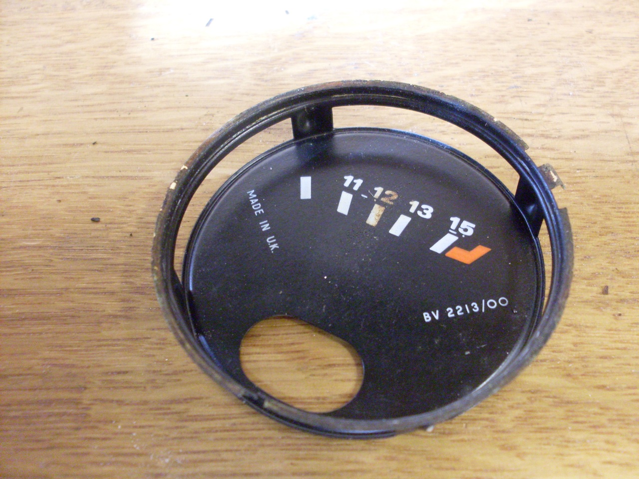
Even though the
construction of the movement is the same for all three electrical
instruments, they aren't interchangeable. The
coil for the voltmeter has a higher resistance, since it may be exposed
to voltages well over 14 volts, while the other gauges would normally
operate under 10 volts due to the voltage stabilizer.
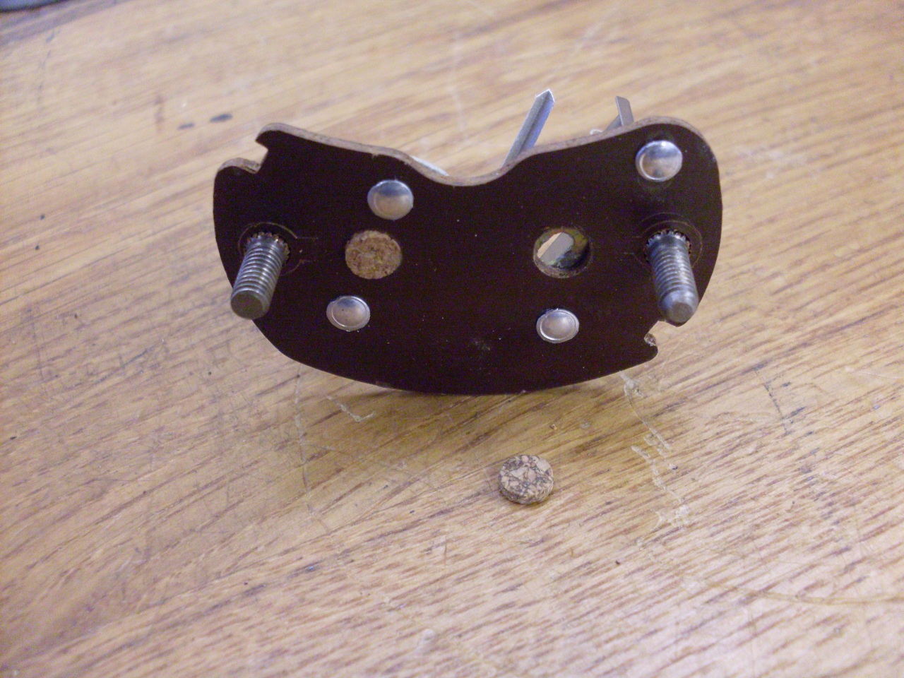
There are a couple of access holes in the rear of the electrical gauges
that offer a way to adjust for proper calibration. I've never
seen any explanation of how to use them, but I fiddled with them a
little to get my voltmeter to be a little more accurate in the center
part of the range. There are supposed to be little cork disks
closing off the access holes, but about half of mine were missing.
A 3/16" hollow punch makes a plug that fits perfectly.
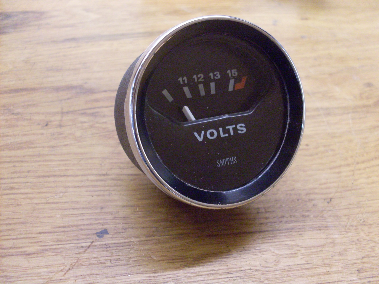
So, with clean cases and working guts, I put everything
back together. I don't know what kind of sealant
Smiths used between the bezel and glass, but I opted to use a stip
caulk compound that worked well. I know there are O
ring seals avilable for this, but I consider the caulk at least as
effective, and I had it on hand. When the bezel is twisted
on, some of the caulk extrudes out from under the bezel. This
is easy to trim off with an Xacto knife, and it indicates a good
seal. I wish I'd had the caulk in black, but I didn't want to
wait for it.
I was able to get the voltmeter to indicate pretty accurately, but
there are other sources of error. There is hysteresis for
one: the gauge reads differently when the voltage is
decreasing than when it is increasing. It's probably due to
slop in the mechanical linkage to the pointer.


The oil pressure gauge is not the same as the other gauges inside.
It is a fully mechanical gauge based on a Bourdon tube, which
is a curled, flattened tube that wants to straighten out when
pressurized. A linkage mechanism amplifies and
transmits the motion of the tube to the pointer.

The oil gauge pointer was pretty yellowed, so I repainted it and all
the other pointers white so they would match.
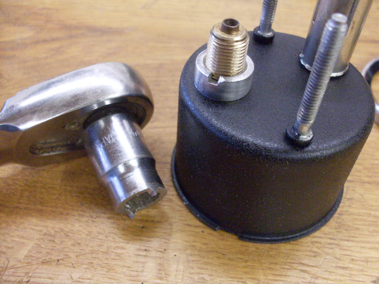
This is a little spanner tool to remove and replace the nut on the back
of the oil gauge.
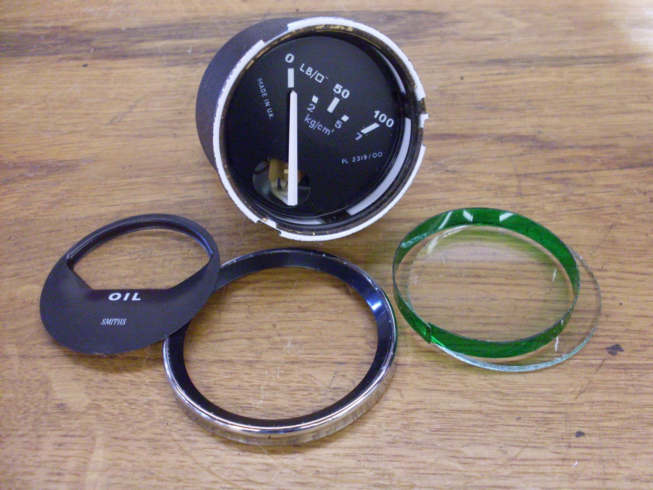
The parts pof the oil gauge, showing the illumination filter strip.
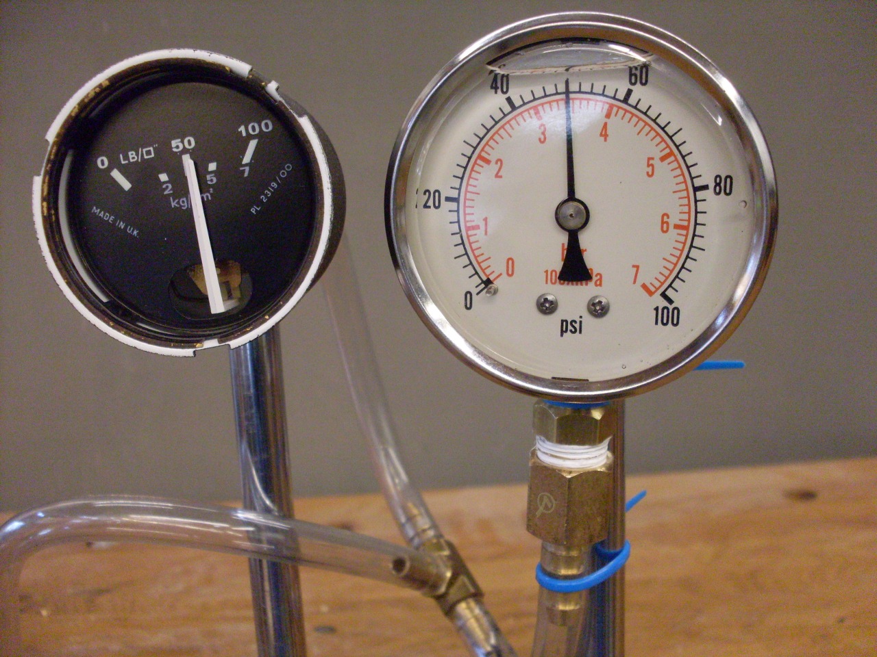
Checked calibration on the oil gauge. It was very close.
Replated the mounting hardware, and these go on the shelf with the speedometer
and tachometer
while I see to a new dash.
One interesting thing on the mounting hardware. The aluminum
finger nuts that secure the oil pressure gauge and the tach and speedo
all appear to be identical. They are not. The oil gauge nuts are
tapped 8-32, while the tach/speedo nuts are 3BA, which is a few
thousandths larger than 8-32, and 34.8 threads per inch. The nuts
can be forced onto the wrong stud, but the threads won't be happy.
Comments to: elhollin1@yahoo.com
To my
other TR6 pages