To my other TR6 pages
December 18th, 2014
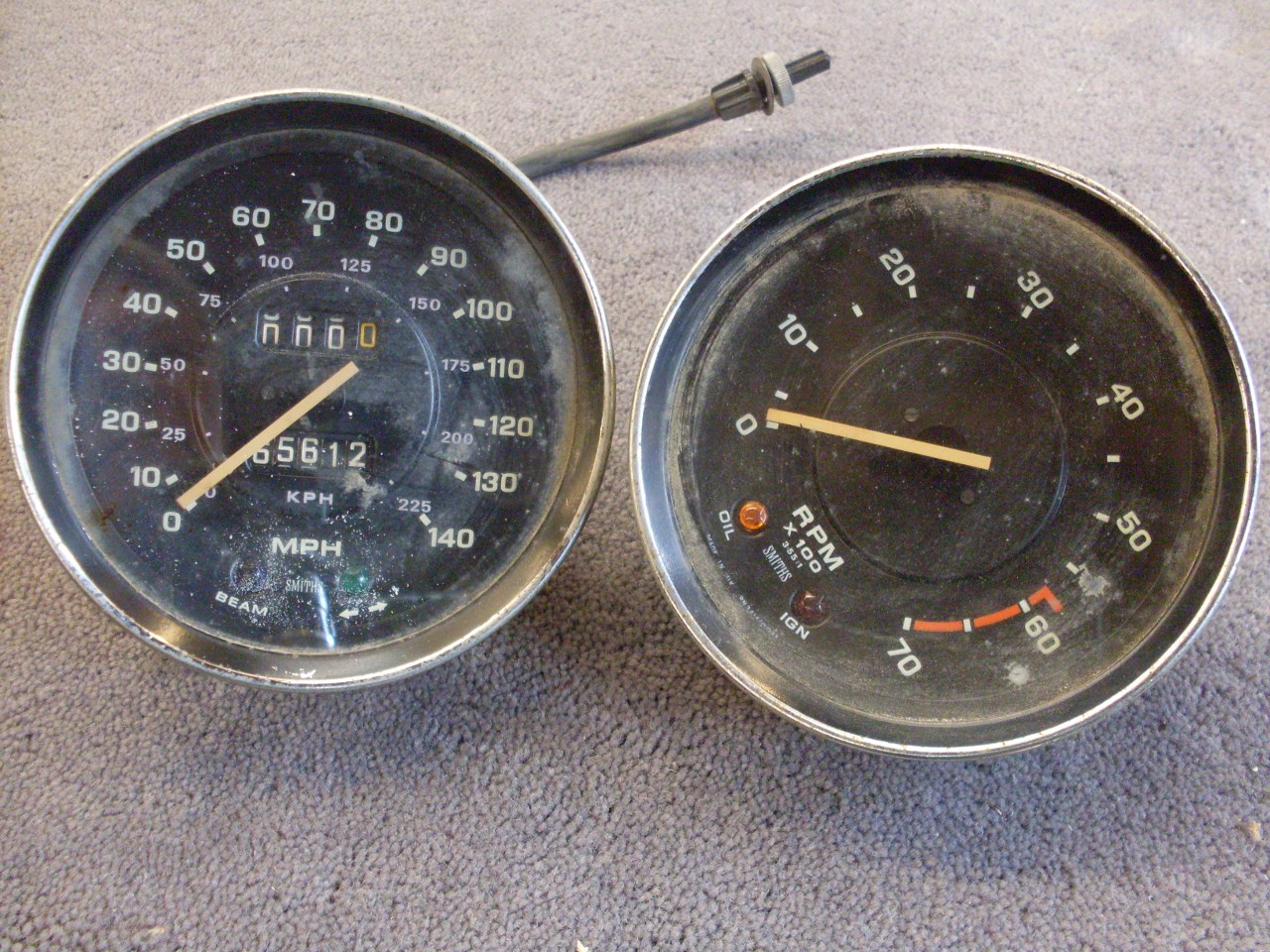
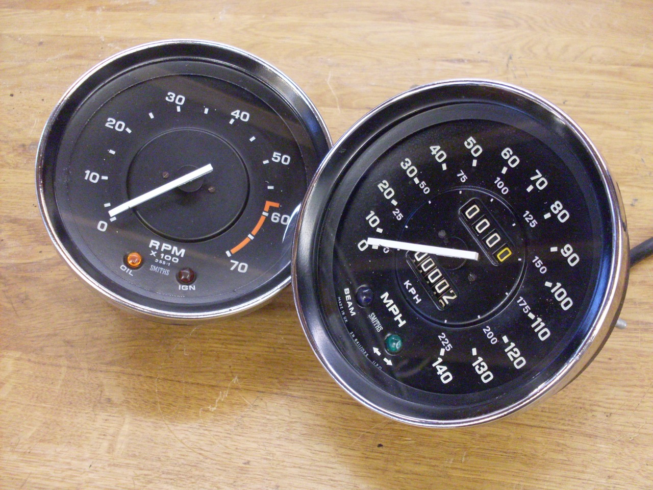
Tachometer and Speedometer
[Click the pics for a better view]
My speedo and tach were both intact, but I remember having some trouble with both of them before I put the car away.
I
started with the tach because it is simpler. When I inserted a
small flat screwdriver into the drive spindle of the tach and apun it
between my fingers, there was sometimes a chatter or stutter to the
rotation, suggesting to me a worn bush.
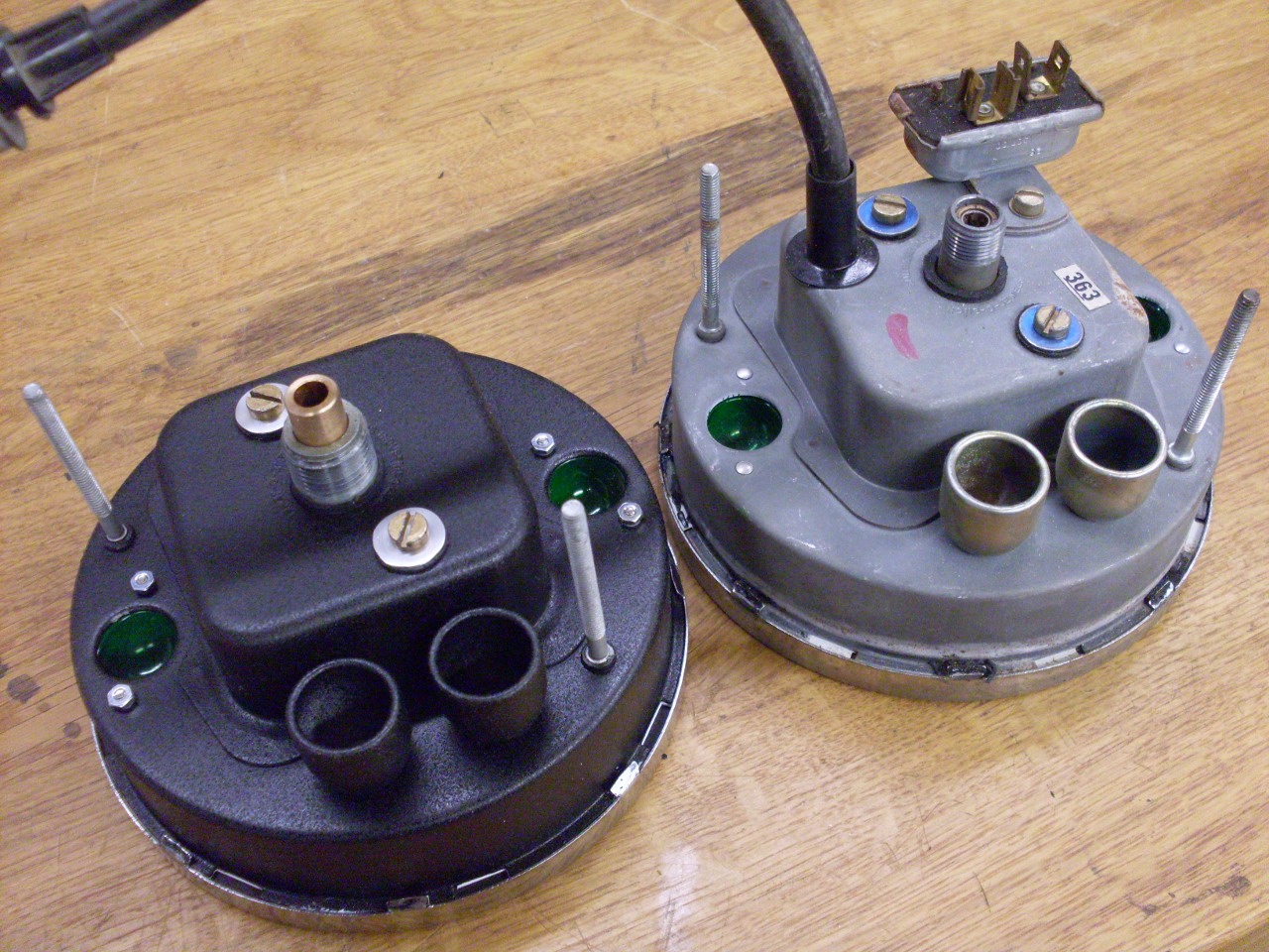
The front bezel twists, and pops off, while the internal mechanism is released by two screws in the back.
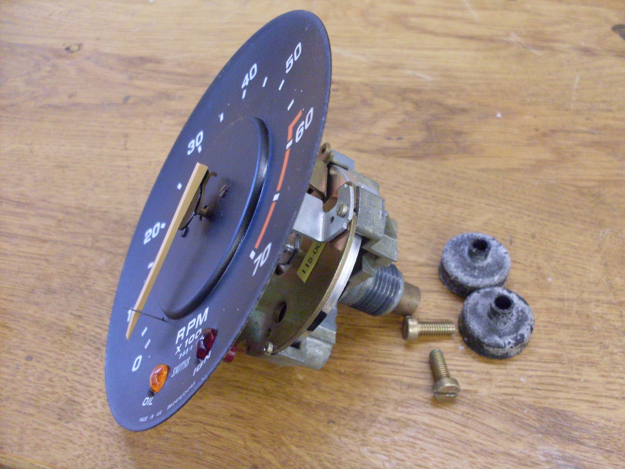
Two more small screws release the front face after the pointer is carefully pried off.

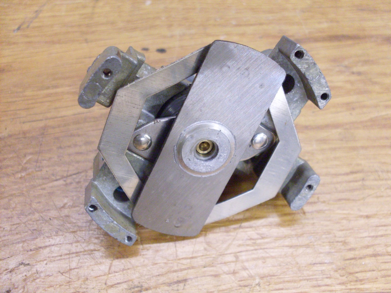
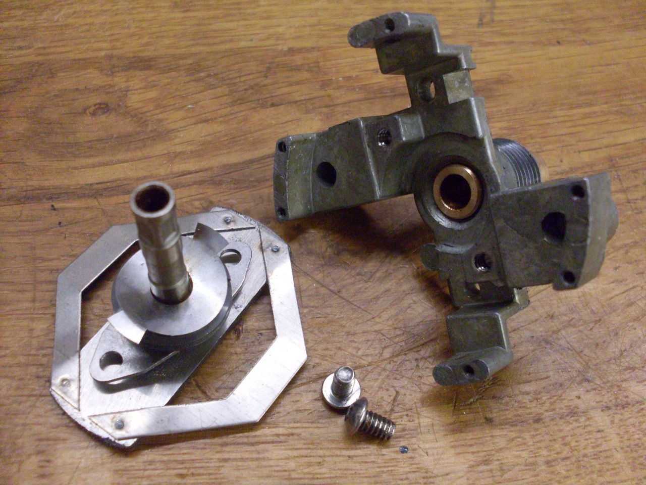
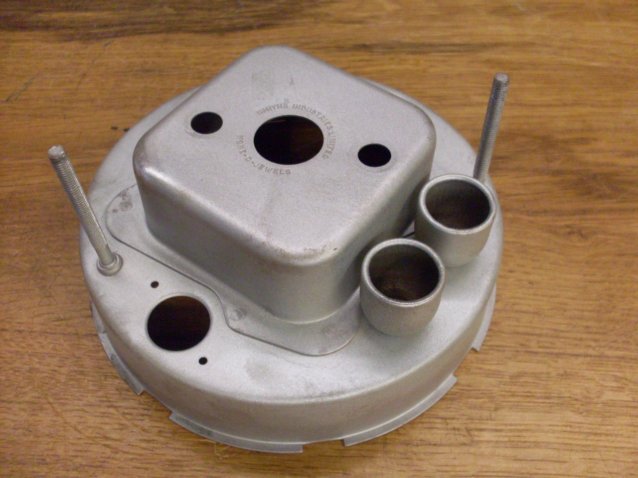
The
innards reveal how the tachometer works: When the input spindle
is spun, it turns a bar magnet inside an aluminum cup. The moving
magnetic field of the magnet induces eddy currents in the cup, which in
turn create their own magnetic field. The two fields interact
such that the cup tries to rotate with the magnet with a force that is
proportional to the speed of the magnet. The cup can rotate, but
is restrained with a small spiral spring so that the deflection of the
cup is determined by the speed of the magnet. The pointer for the
tach is attached to the small spindle that holds the cup.
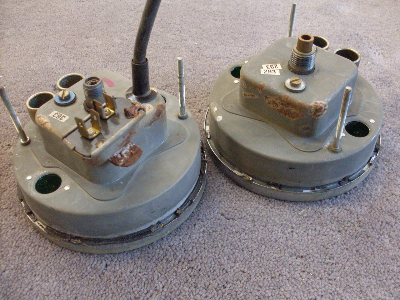
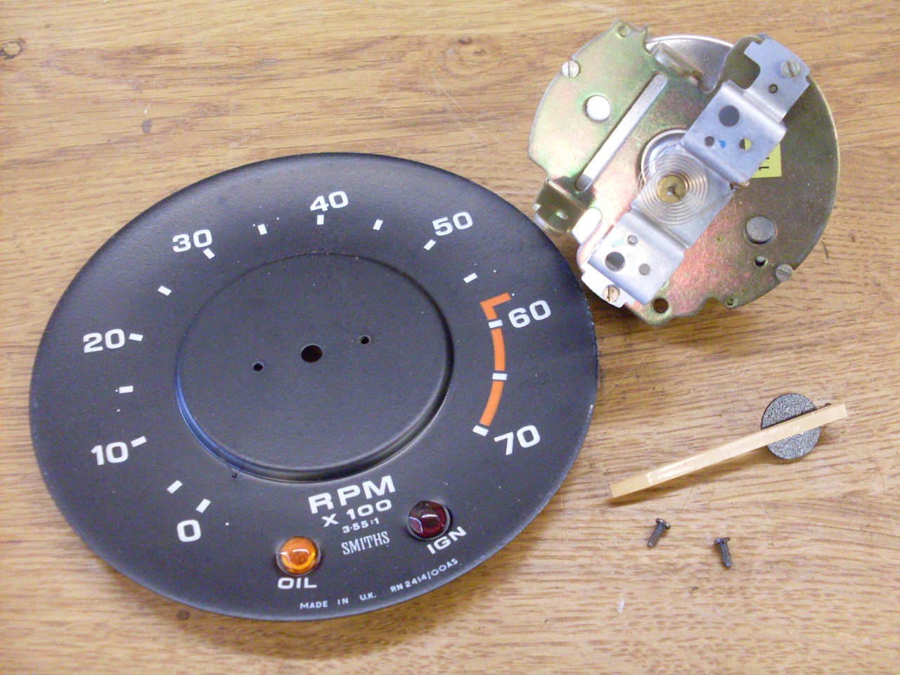
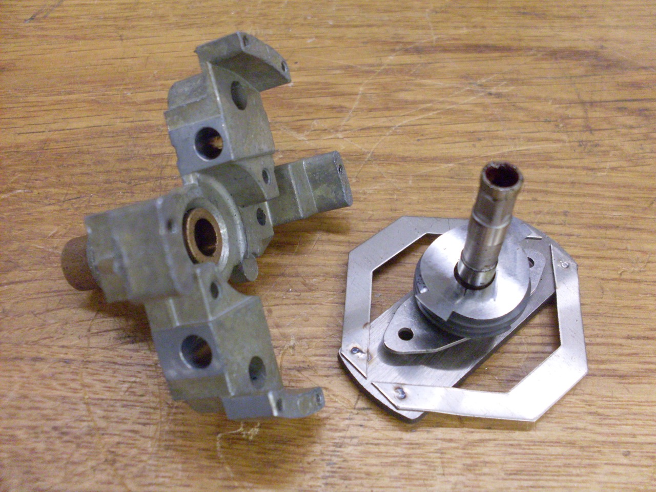
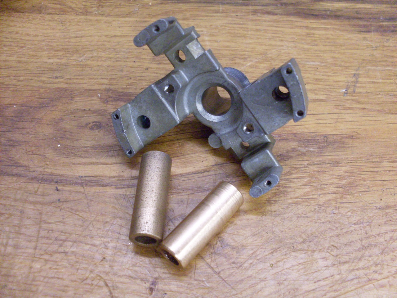
The second picture below shows the magnet and cup separated.

Since
I needed to replace the bushing that the input spindle rides in, I had
to get the spindle out of the bushing. Unfortunately, there was a
keeper on the spindle that was riveted to the main casting. The
two rivet heads are visible in the second picture below.
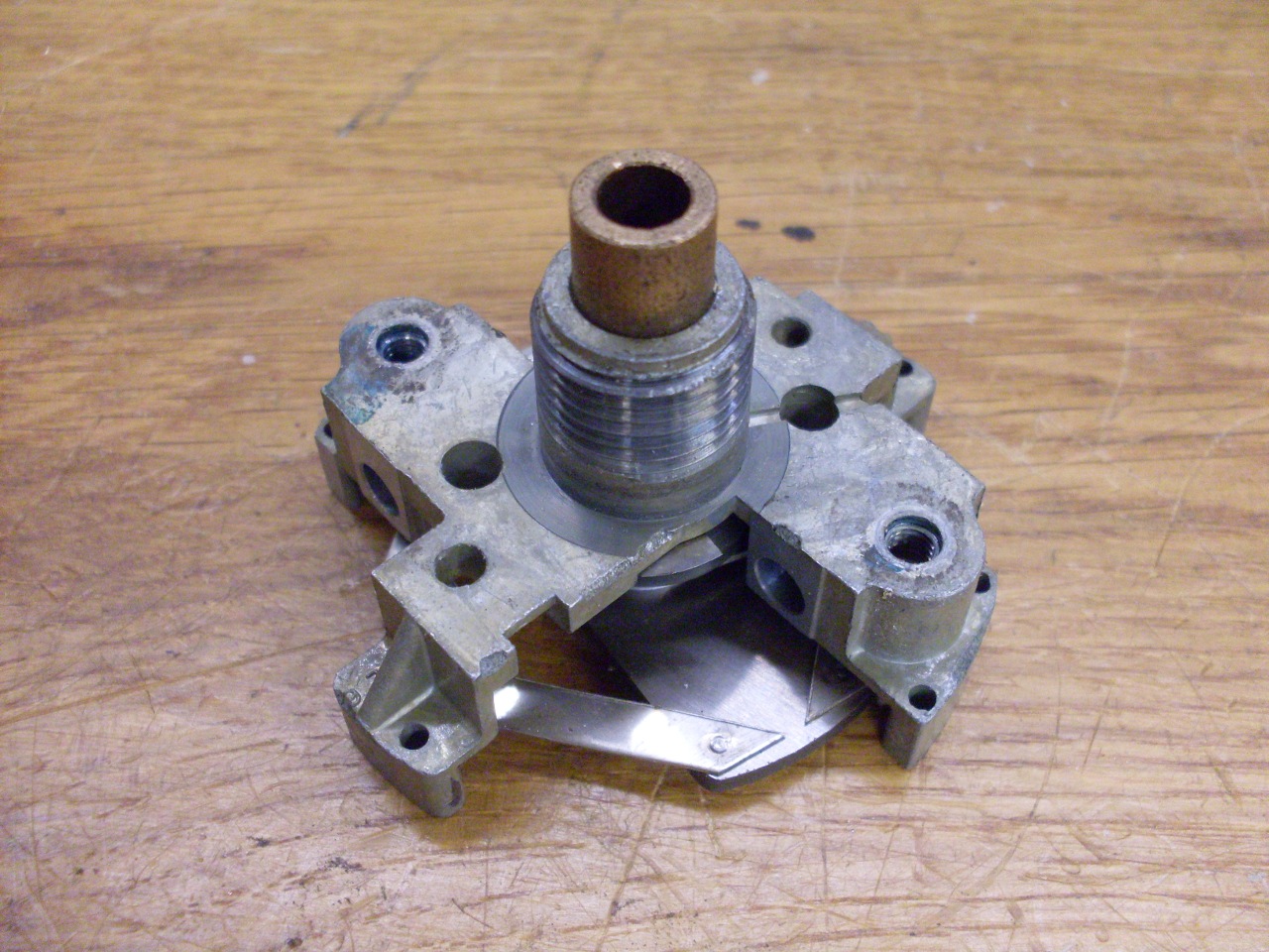
I drilled out the two copper rivets and removed the magnet and spindle.
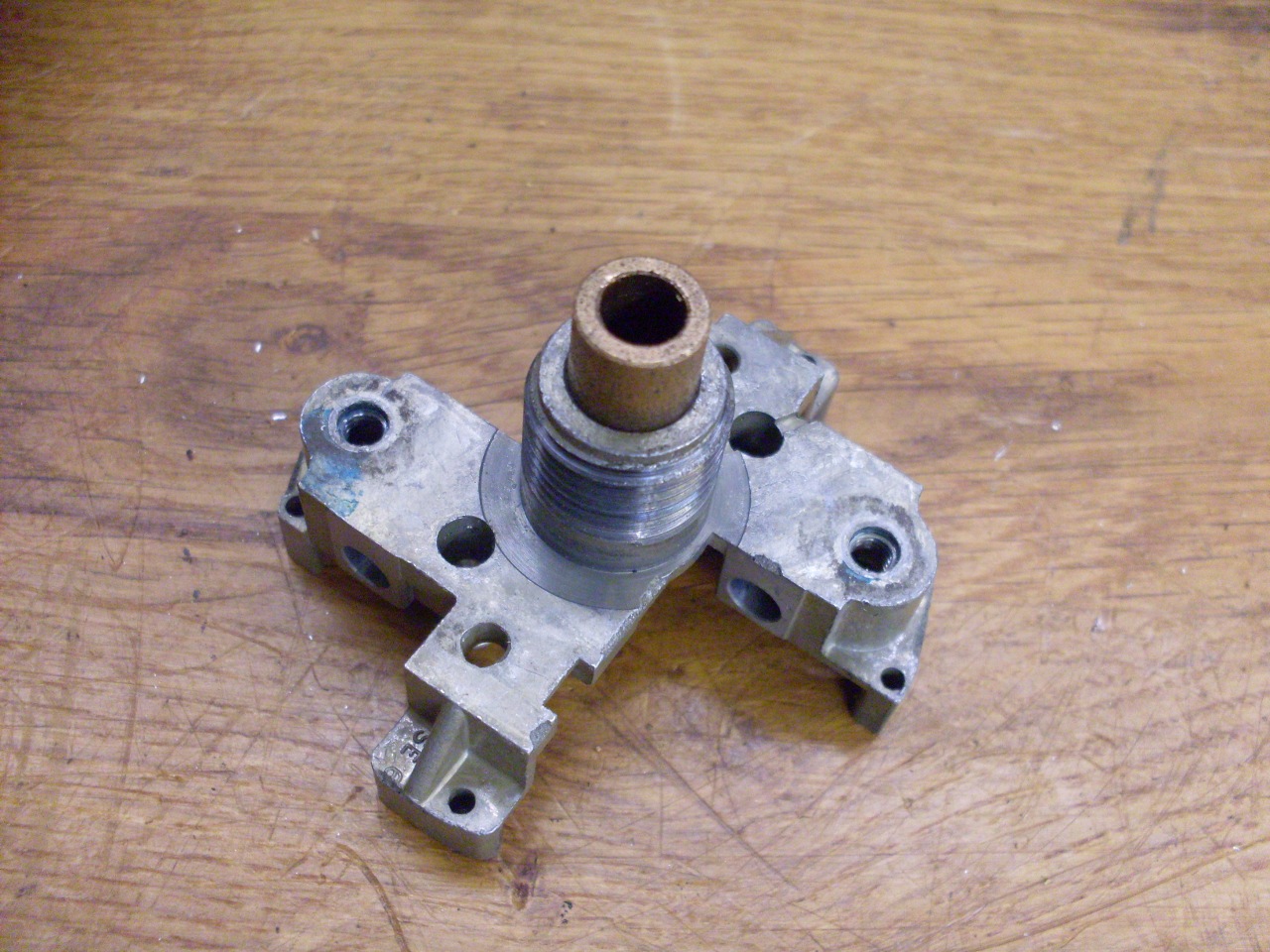
I
wasn't able to locate any replacement bushings, either as replacement
parts or from general industrial suppliers. It is a bit of an odd
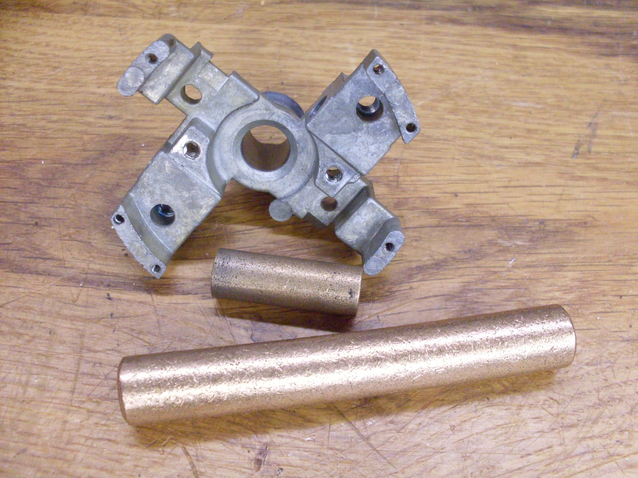
size--3/8" OD and 6 mm ID, and fairly long. My fallback was to
make a bushing. I started with a hunk of raw Oilite rod, which is
what the original bushing appeared to be made from. Oilite is an
oil impregnated pourous bronze, which is ideal for use in places that
probably won't get external lubrication. I brought the bush to
final ID with a 6 mm reamer after it was pressed into the casting.
The spindle fit was good, and showed no more tendency to chatter.
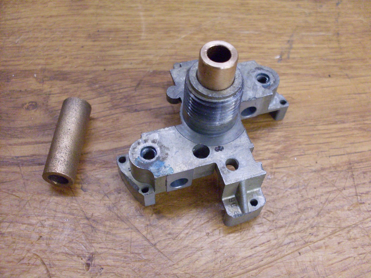
The
spindle assembly then had to be remounted on the casting. I
didn't have the right kind of rivets, so I driled and tapped the rivet
holes for some 6-32 screws. I really should have used smaller
screws since the holes in the spindle keeper had to be enlarged.
Also, I had to reduce the height of the button head screws
slightly so the magnet wouldn't drag on them. It seemed like a
good idea to use non-magnetic screws to replace the copper rivets, so
the screws were non-magnetic stainless.
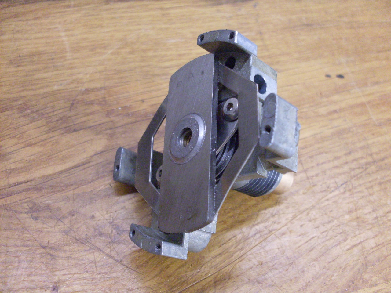
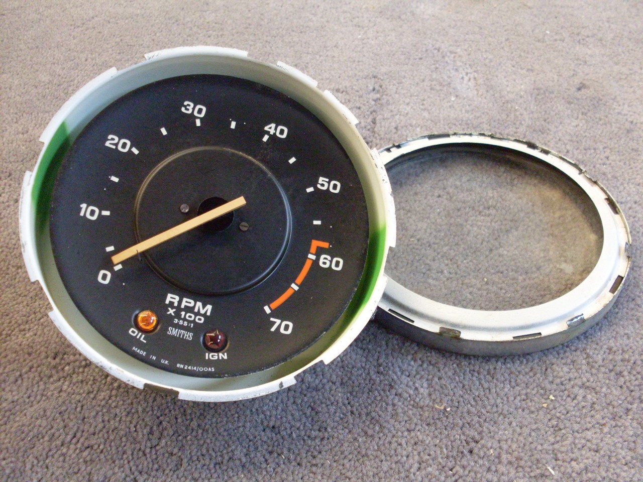
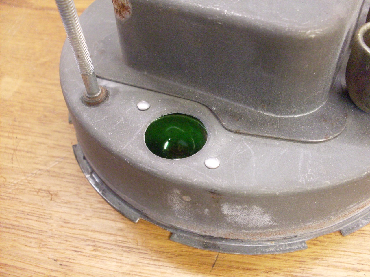
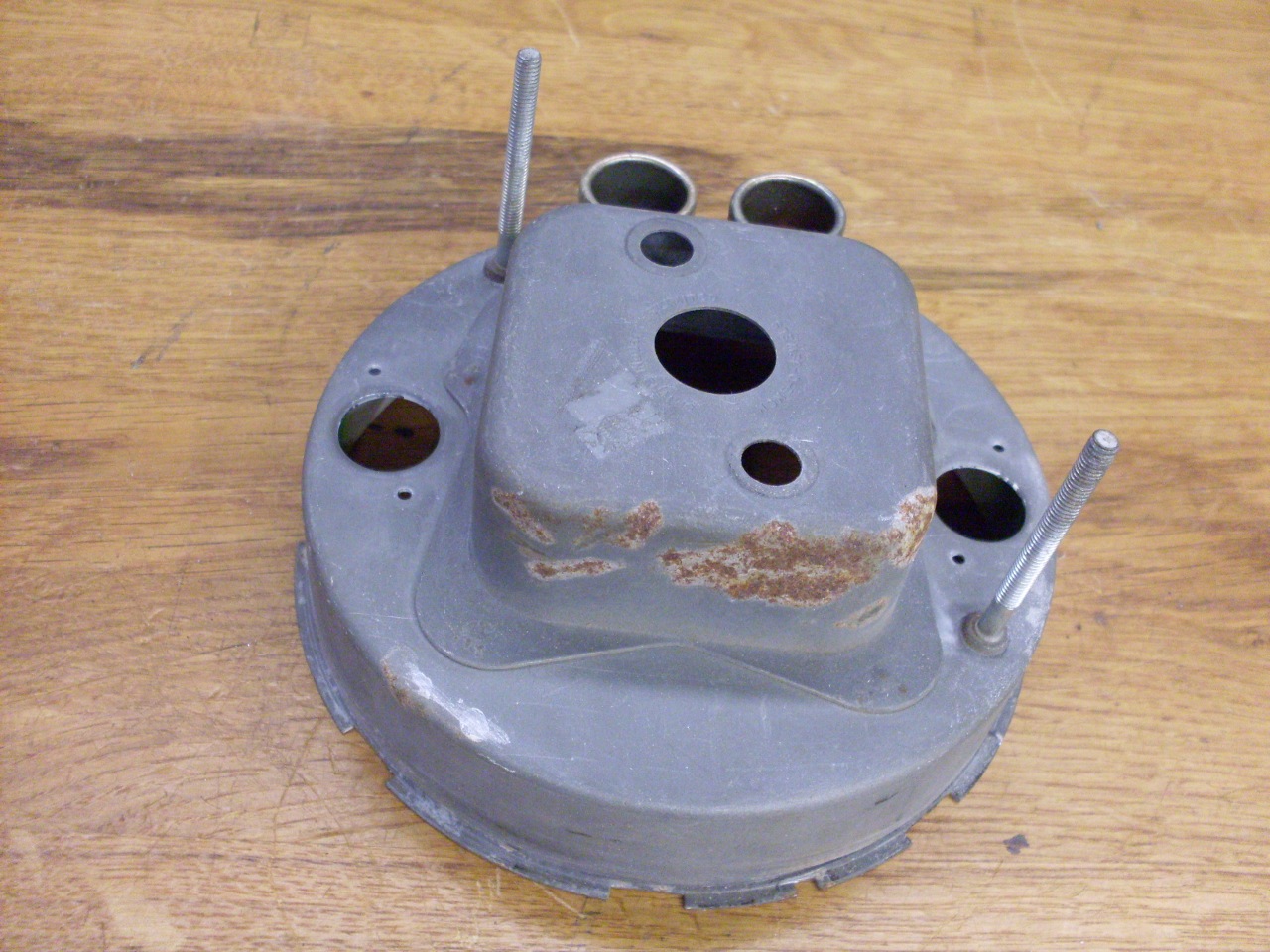
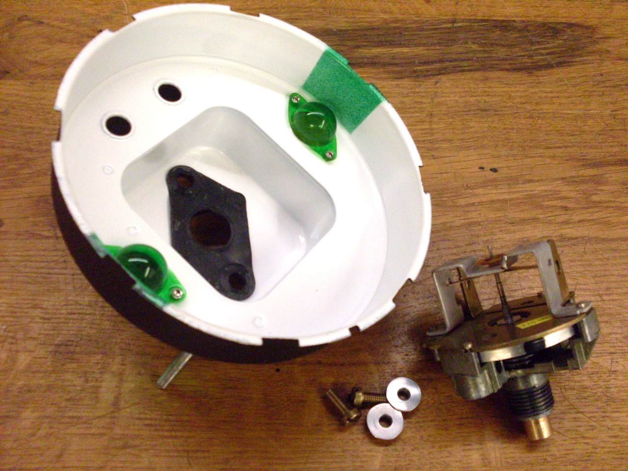
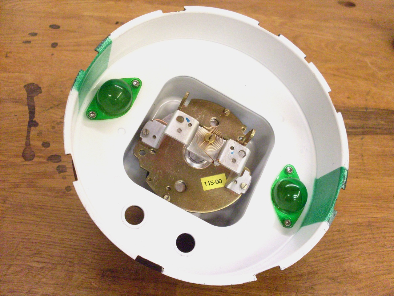
With
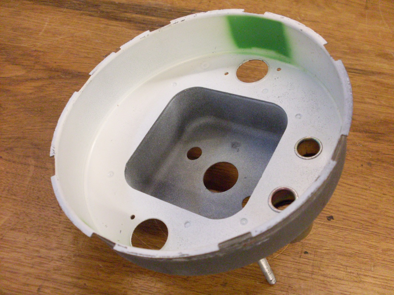
that repair done, I turned to the case. The case was apparently
bare zinc plated steel on the outside, but had some rust. There was
yellowed white
paint on the inside. There are also a couple of translucent green
plastic domes riveted in the case for the instrument lights. I
wanted to bead blast the inside of the case, so the plastic domes had
to go. I expect that the green paint patch was to subdue the
light intensity close to the bulb.
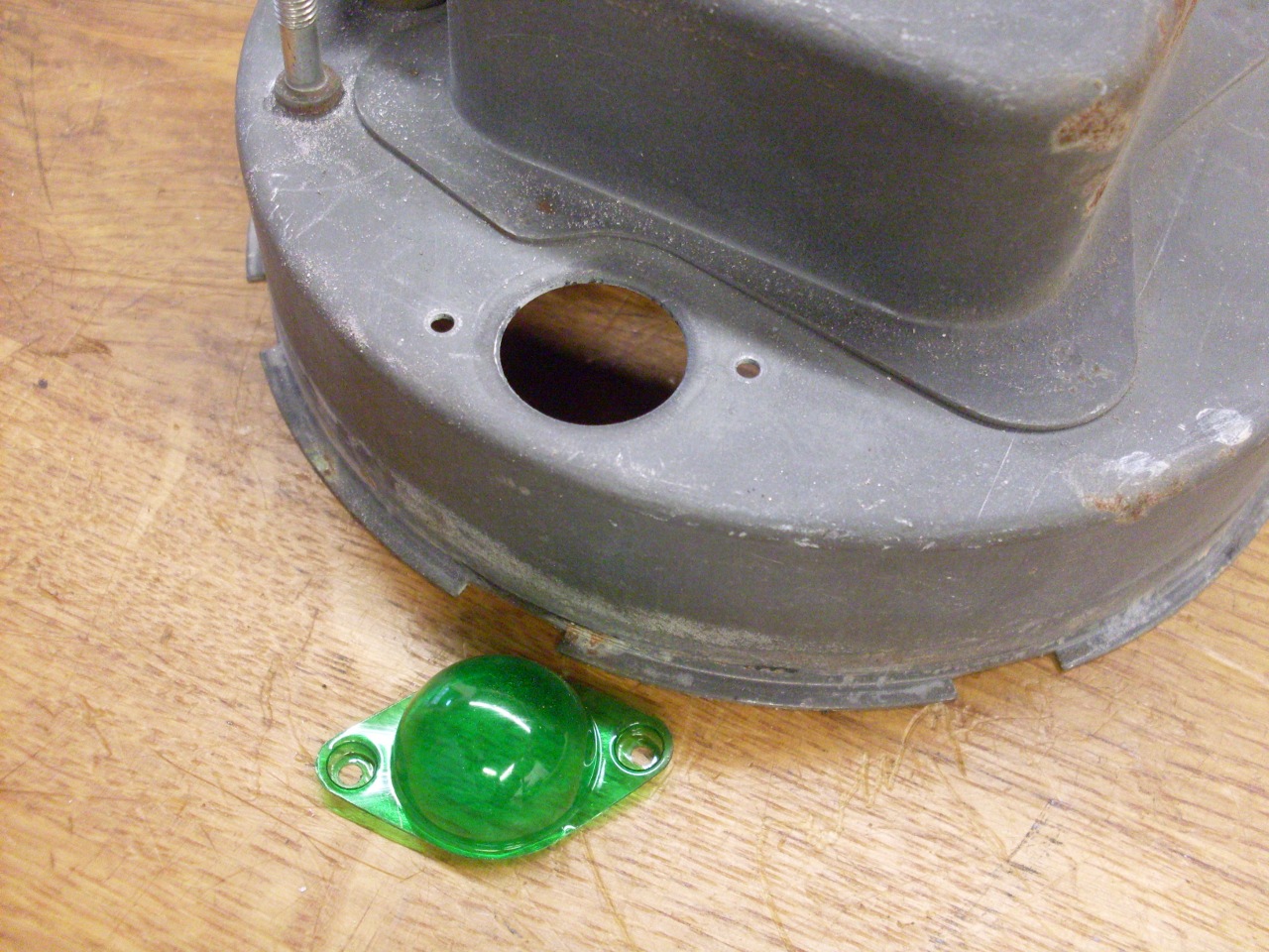
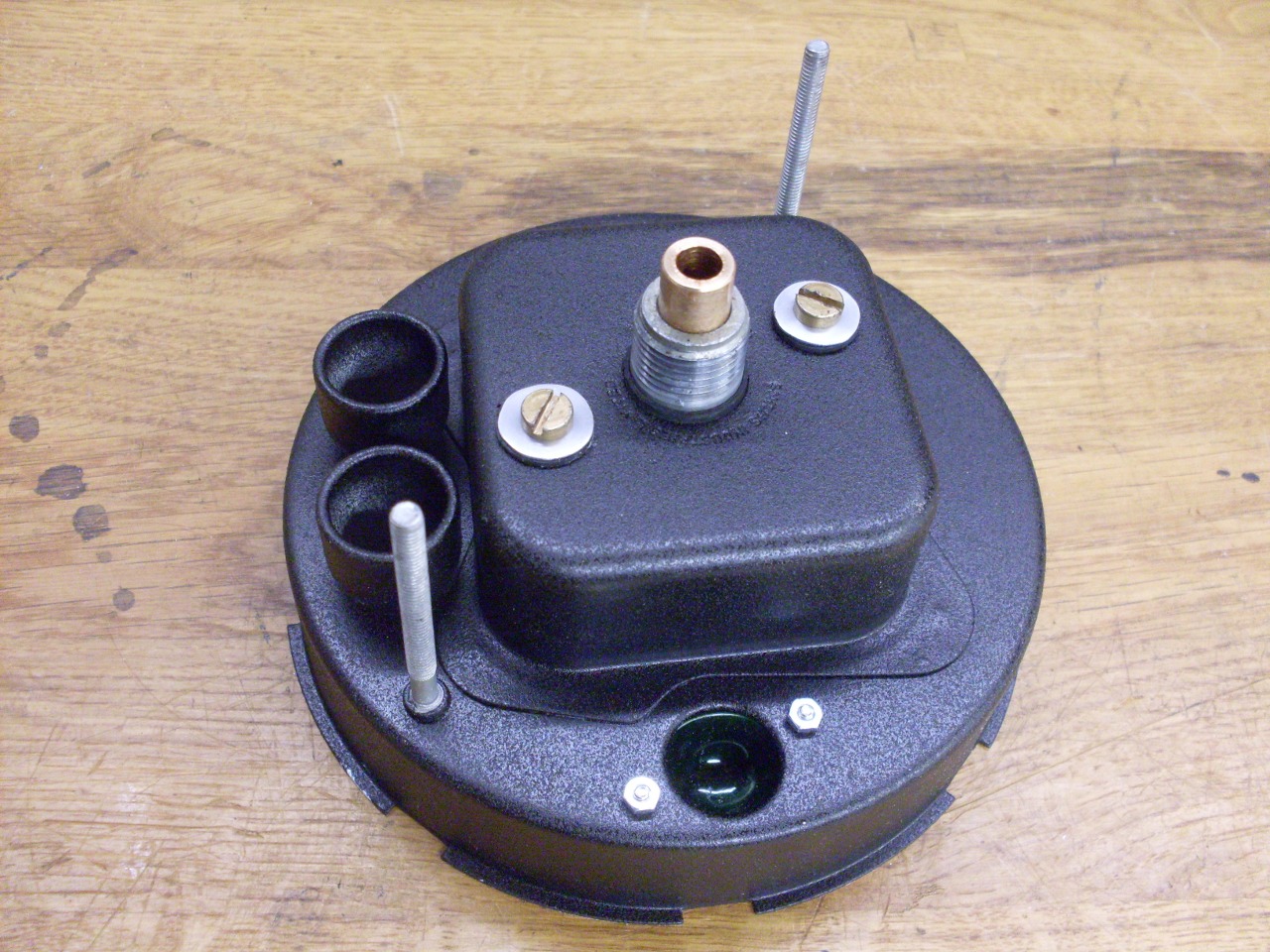
After bead blasting and painting the inside and outside. The little domes were remounted with 2-56 screws and nuts.


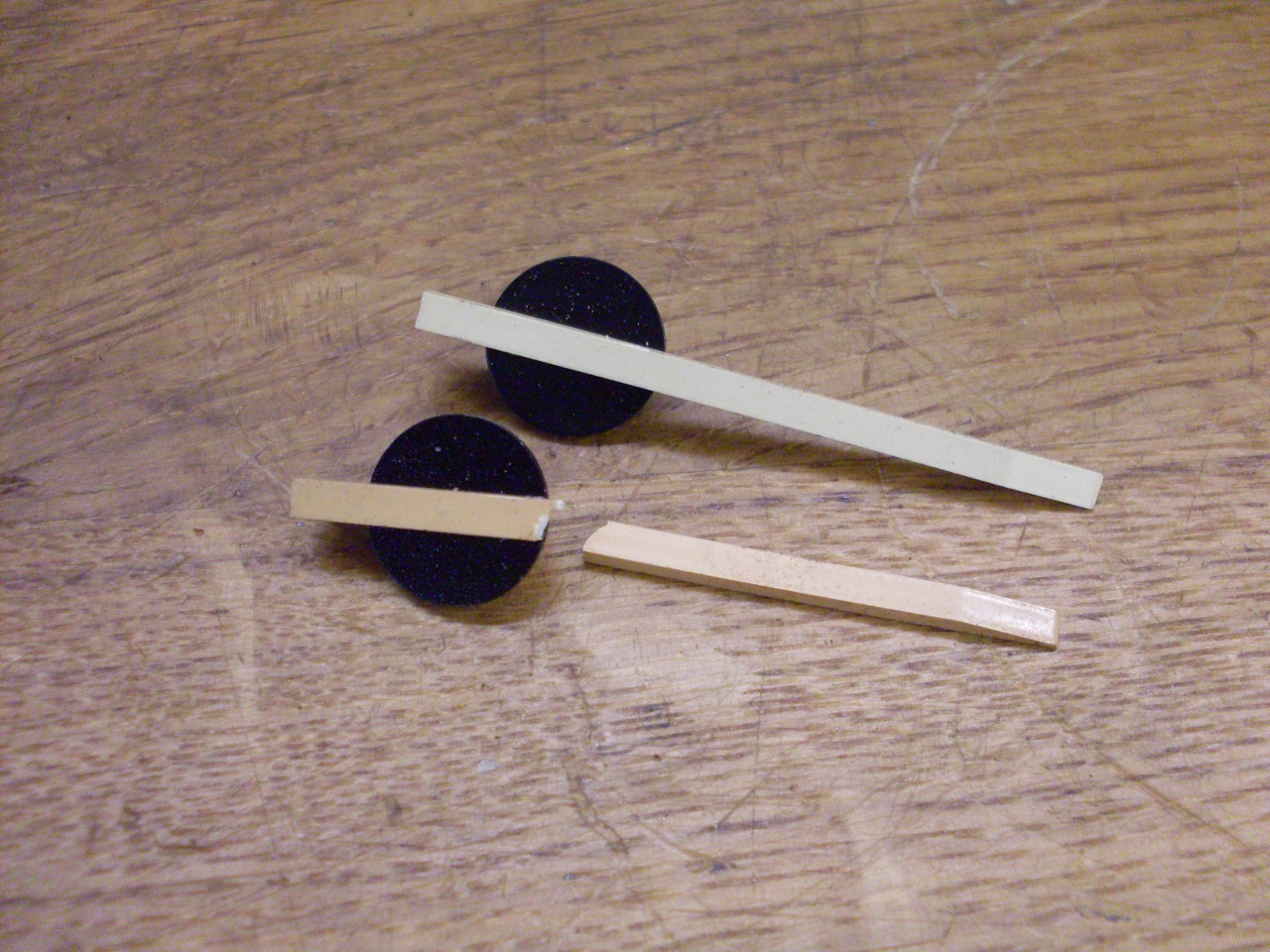
Before
I put everything back together, I wanted to check the operation and
calibration of the instrument. I remounted the dial face, and
when I retrieved the pointer, I was horrified to find it snapped in
two. I'm not really sure how it happened. The pointers are not available new, and used ones are
getting rare. A generous member on one of the popular TR6 forums
kindly donated a junk tachometer for the pointer. I noticed that
the donor pointer was much whiter than mine, but still yellowish
compared the the white lettering on the dial face. Before I
installed it, I masked and painted the pointer a whiter white.
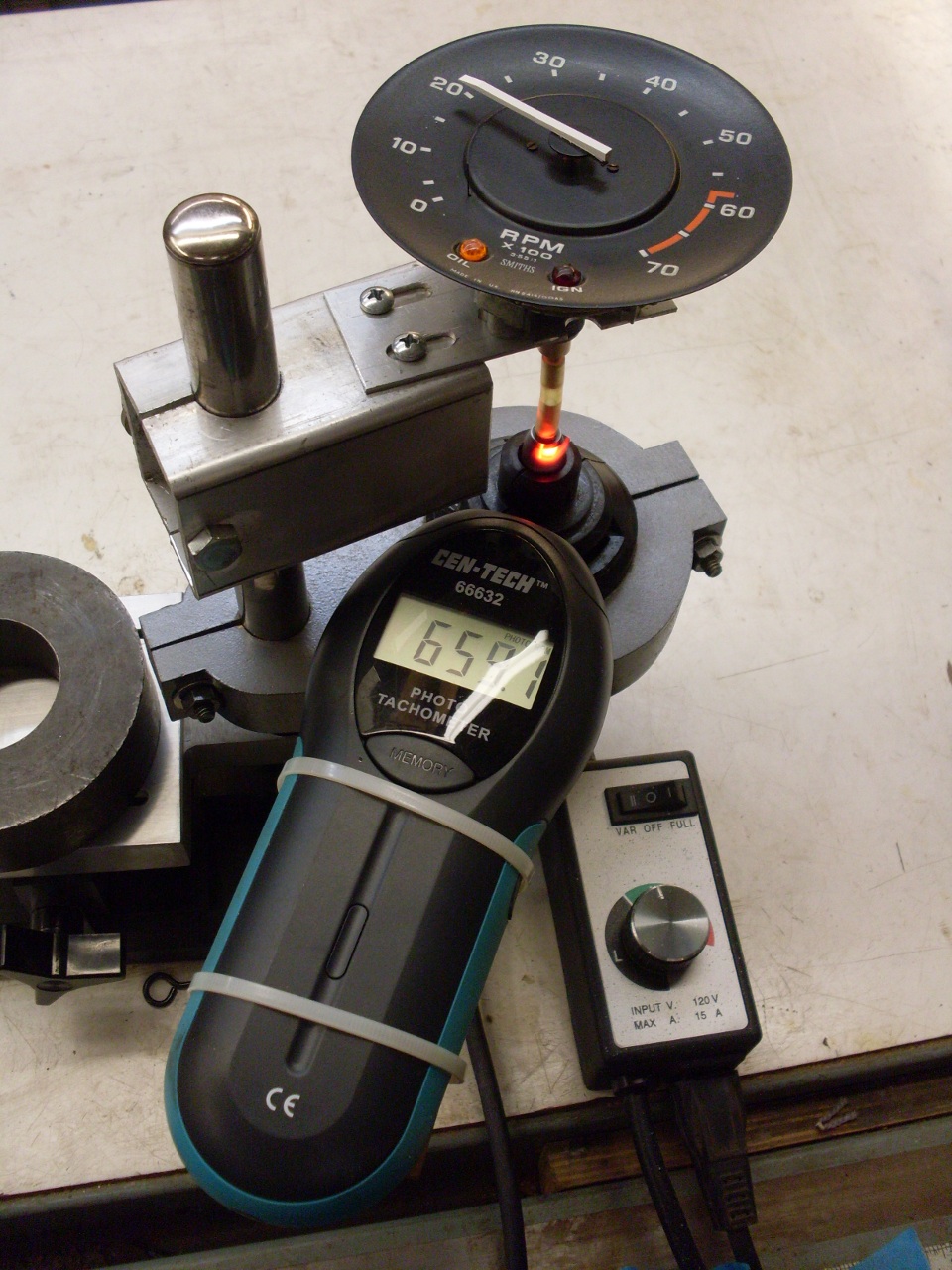
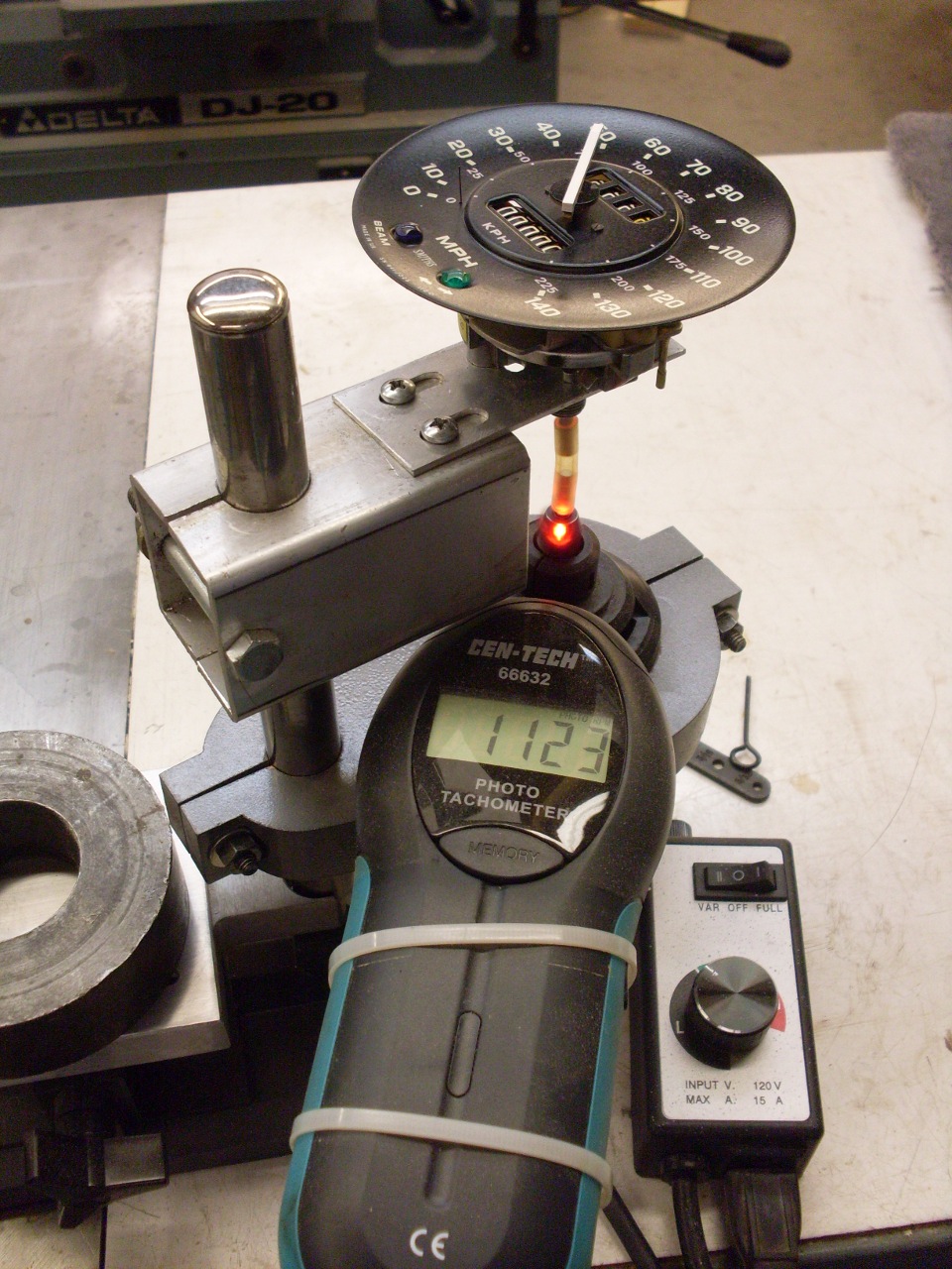
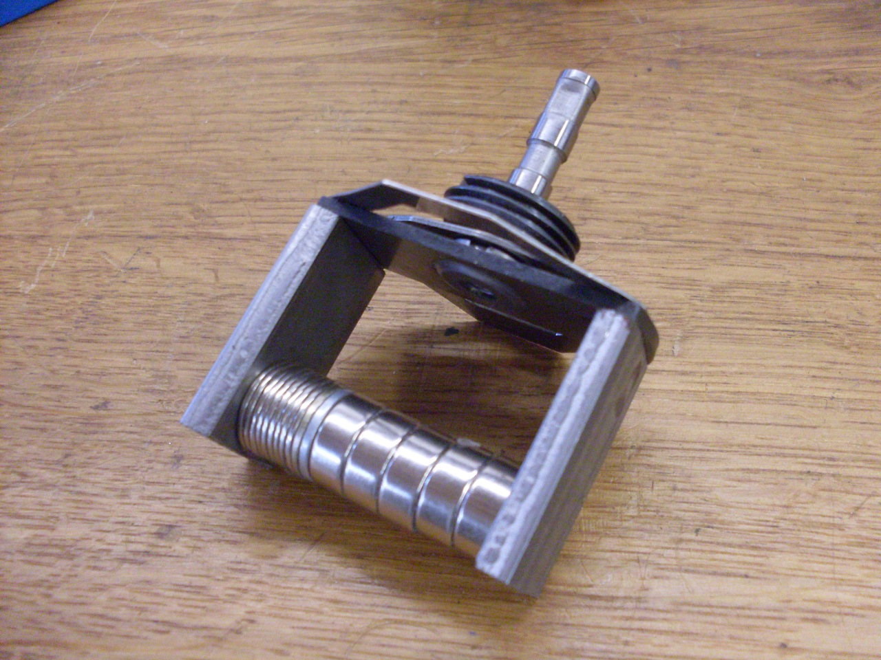
This is a calibration rig I put toghether when I rebuilt the instruments on my Triumph motorcycle.
It consists of a univeral motor (a Sears Craftsman chain saw
sharpener) modified to run in reverse, a speed controller, an optical
tachometer to read out the speed of the motor, and a stand to mount
everything on. I can dial in a speed for the motor, and note the
reading on the instrument. This tach is marked "3.55:1" on the
dial, which means that the indication on the dial should be 3.55 times
the RPM of the tach inner cable. (The tach drive gears on the
distributor have a ratio of 16:9, and since the distributor runs and
half the speed of the engine, the RPM ratio between the engine and the
tach cable is 16/9 x 2 = 3.5555..., which rounds to 3.56. Smiths
made a small math error.)
The
tach operation was smooth and steady. However, graphing the curve
of dial reading vs input speed, the tach was indicating consistently
about 10% low. I have not run across a source that reveals how to
adjust calibration on the instruments, but I did try a few things.
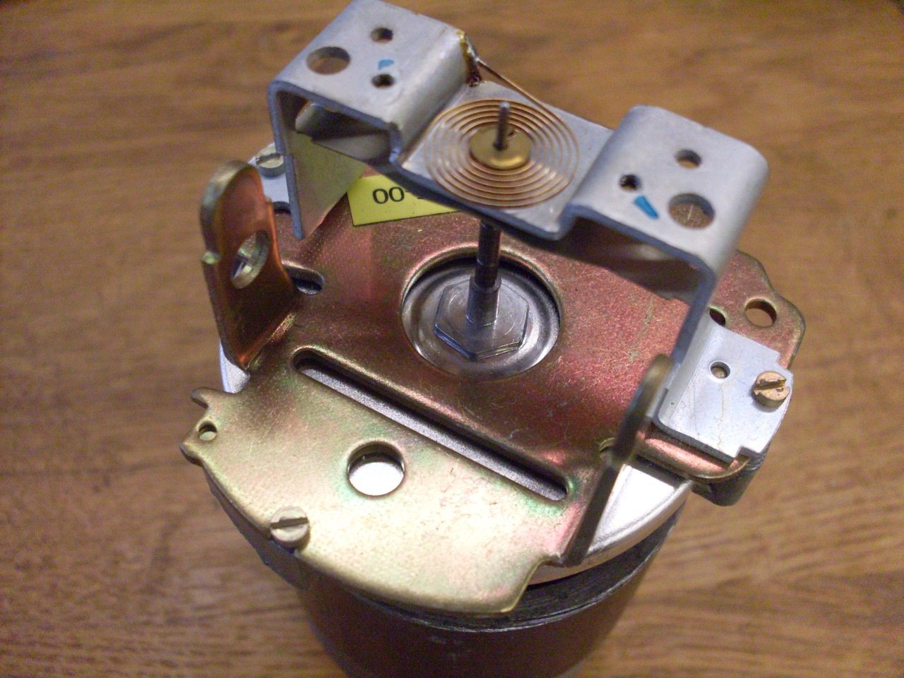
There are some arms that connect the two ends of the magnet, and
they appear to have been bent slightly up toward the disk at some
point. I surmised that this was a calibration adjustment. I
played with this, and it did seem to help a little, but I still
couldn't get the reading to be on the money. I suspect the magnet
has weakened a little in 40 years. Some have gone so far as to
piggyback an additional magnet, but this seemed a little anal, even to
me. In the end, I decided to be content with a good-looking,
smoothly operating instrument that reads a little low. In practice, I rarely use the
tach anyway.
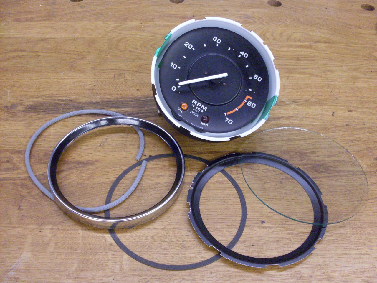
Final assembly continued. The original rubber mounting pad was still in excellent shape.
The
bezel components were still usable except for whatever was in the bezel
next to the front side of the glass. It came out in small shards, and
I'm not sure if it was some kind of gasket or a caulk. I found
some rubber cord used to repair window screens that was the right size
to provide a seal against the glass.
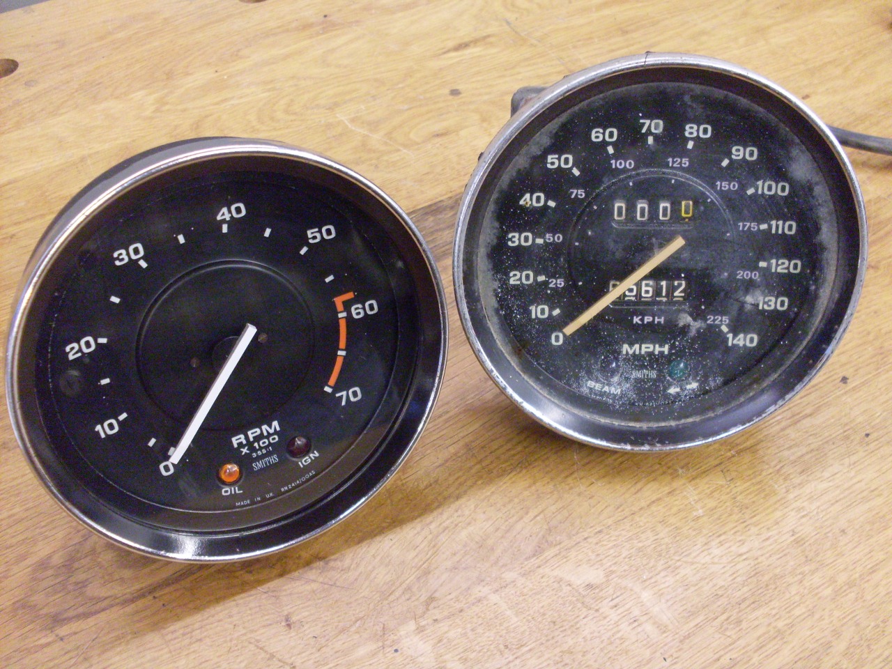
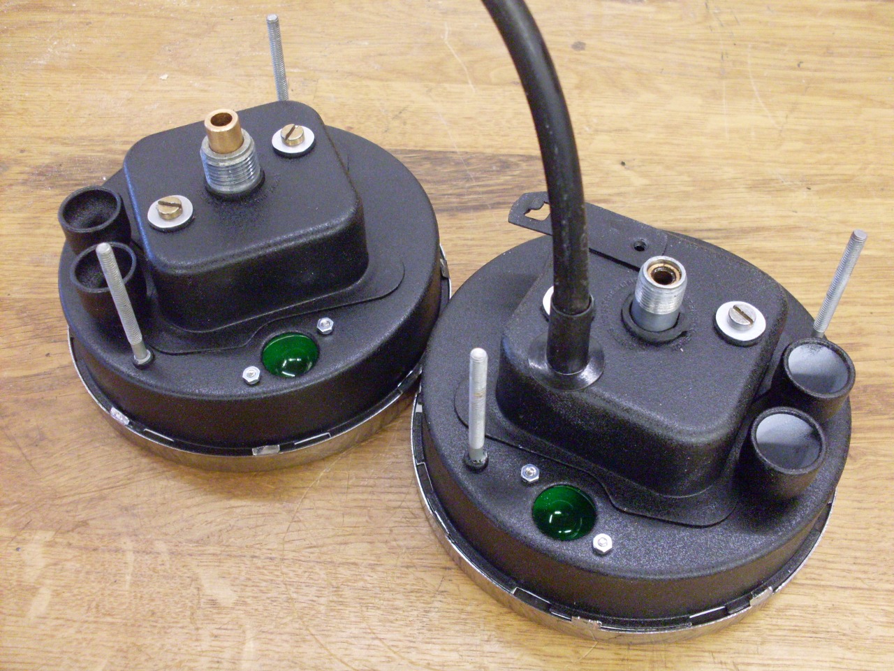
The
speedo is next. It's internal workings are very similar, but it
has all the odomoter gear, too. One good thing is that the input
shaft bushing on the speedo seems to be OK.
I'll update for the speedo if there is anything relavent.
Update--January 7, 2015
The speedometer, though of a design similar to the tach, presented its own special problems.
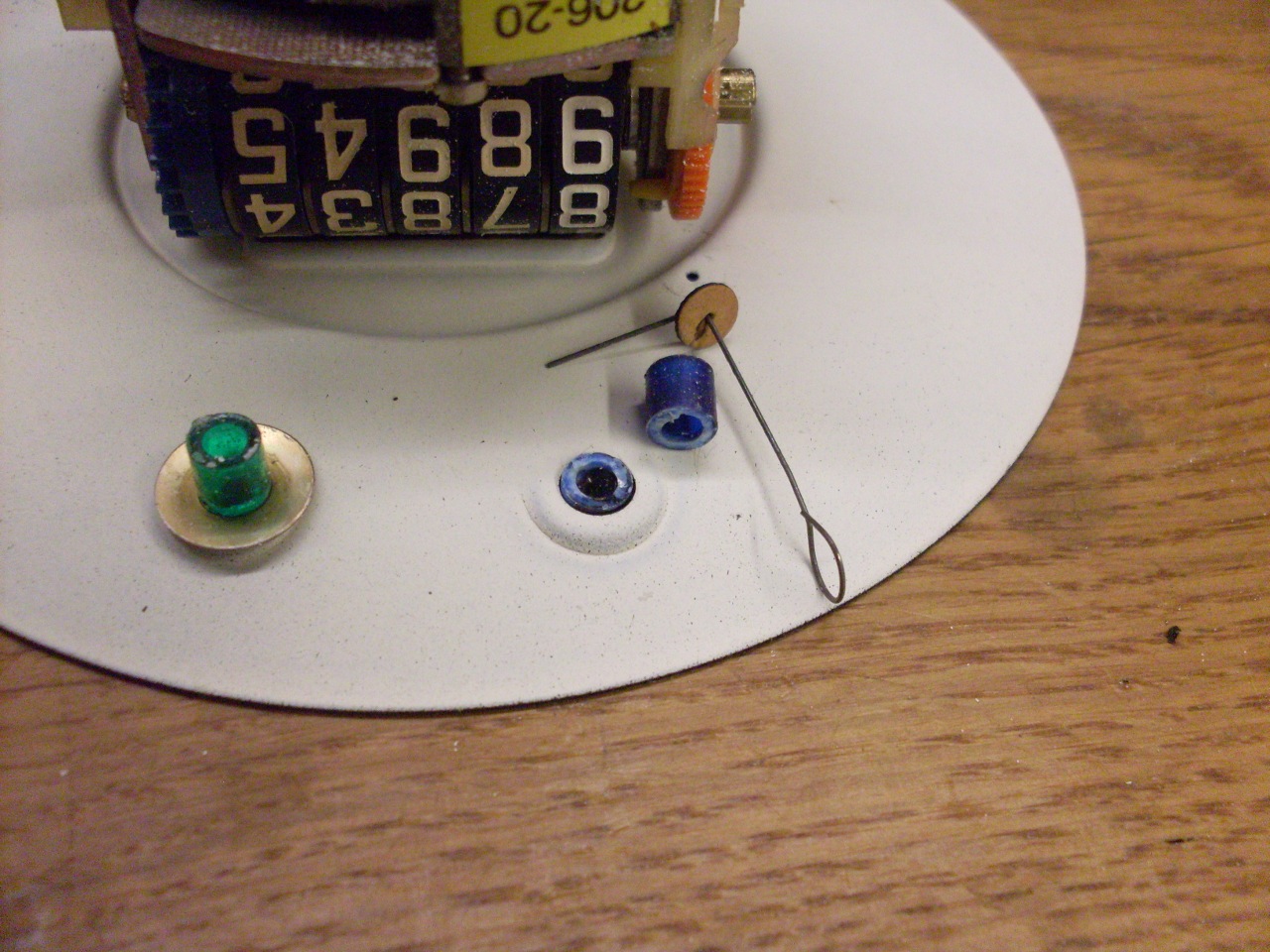
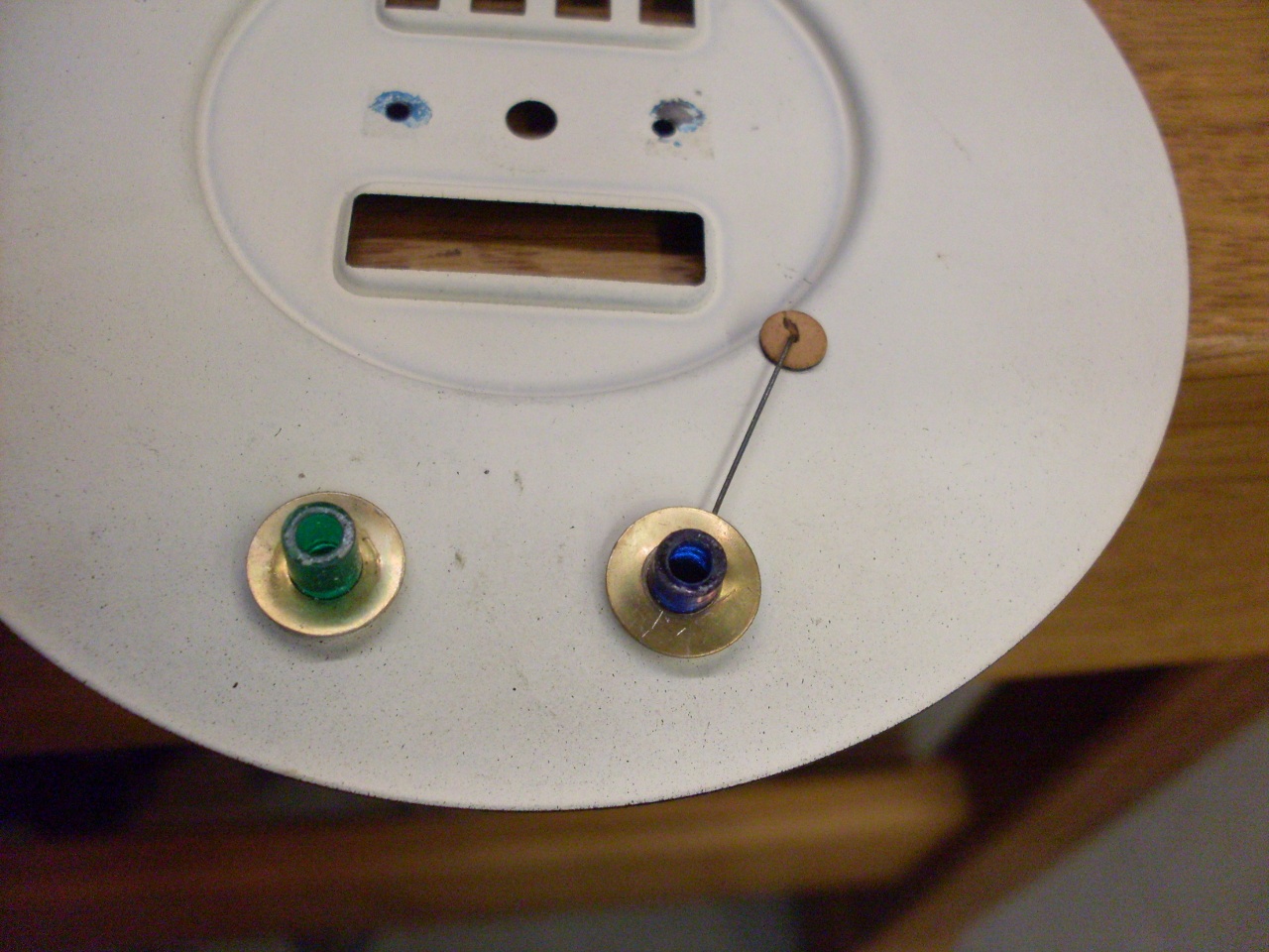
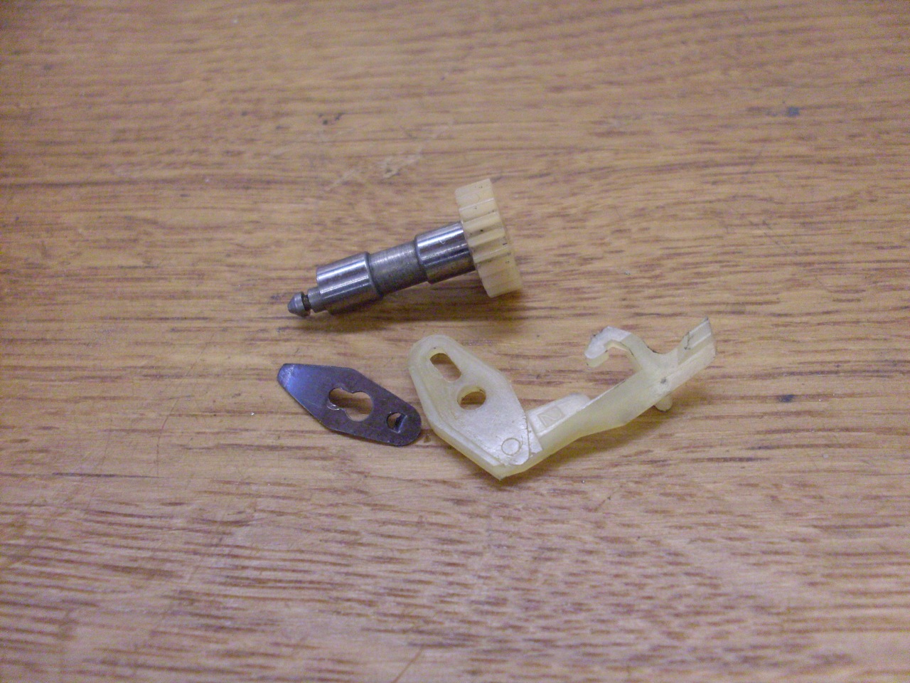
The
first issue explained the rattling sound I heard from inside the case.
The pointer stop wire is normally fixed to the blue lens for the
hi-beam lamp, but the barrel behind the lens had broken, and the wire
and back part of the lens were loose in the case, along with the little
brass washer that holds the wire down.
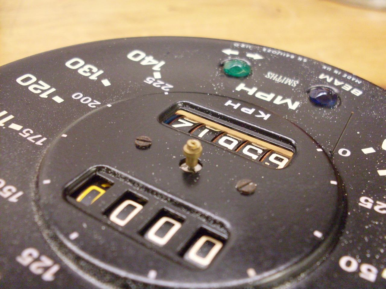
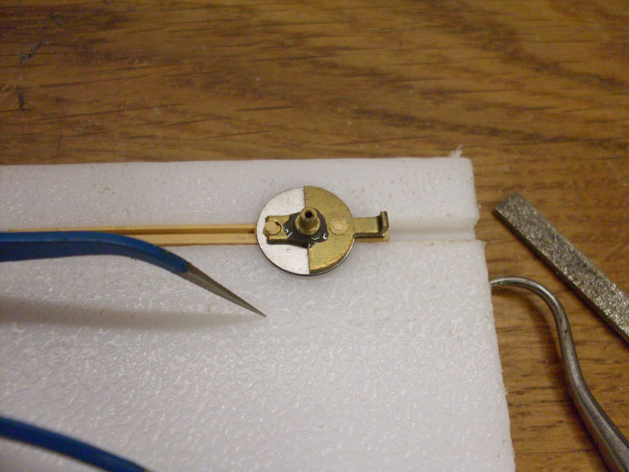
Next
issue came in removing the pointer. That little brass ferrule is
supposed to come off with the pointer, not stay on the spindle.
In my life, I've worked on four tach/speedos--two on my Triumph
motorcycle restoration, and these two. On three out of the
four, I had pointer problems.

Both
of these were fixed with a little of the appropriate adhesive--a
solvent based plastic adhesive for the lens, and a metal filled epoxy
for the pointer (OK, it's JB Weld).
I did also decide to replace the input bushing like for the tach, but the speedo bush has a different OD.
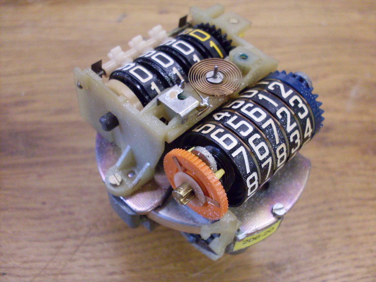
I really wanted to clean the odometer wheels. This is
simple for the trip odometer because they can be rotated with the reset
shaft. However, there is no way to turn the main odometer wheels
on a later instrument other than through the input shaft (which would
take a while), or by removing the wheels.The stack of wheels has a lot
of tiny internal parts that caused some hesitation, but I forged on
anyway. There was a while there where I was really sorry I did
that. After a tense hour or so, everything was cleaned and back
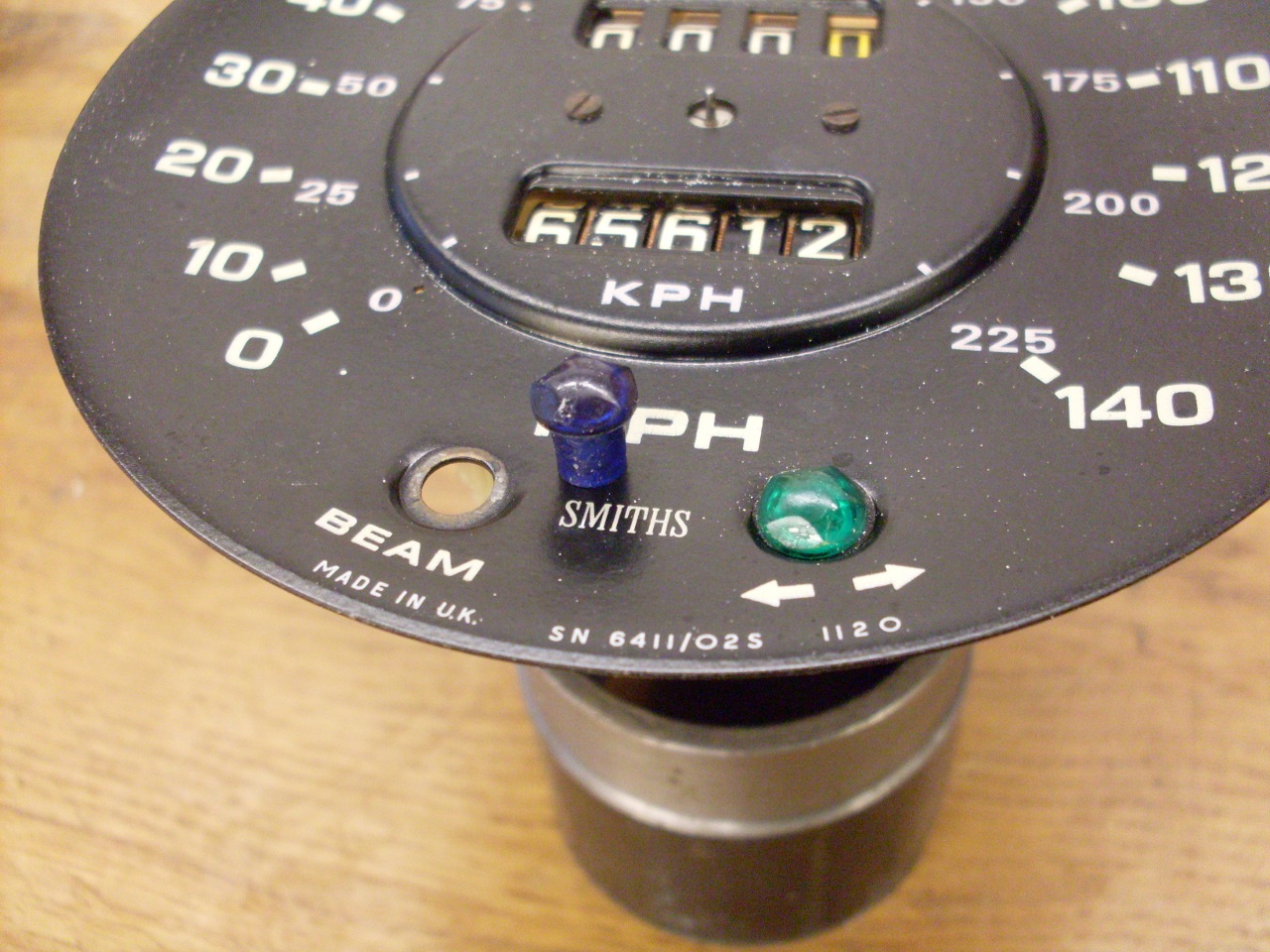
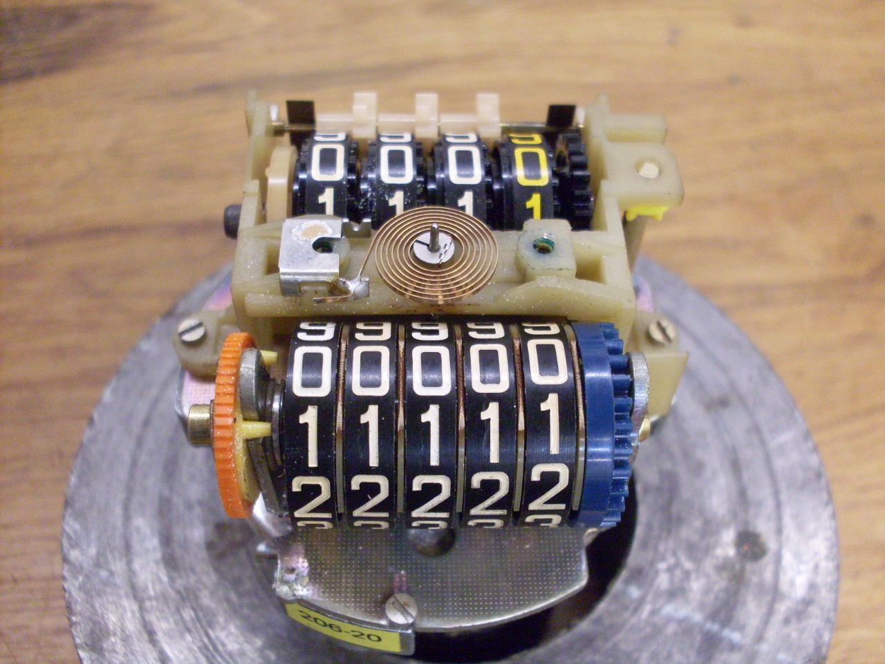
together. I decided to set the wheels back to 00000, since the
number that was on there had no significance anyway--the speedo cable
was broken for much of the time I drove the car.
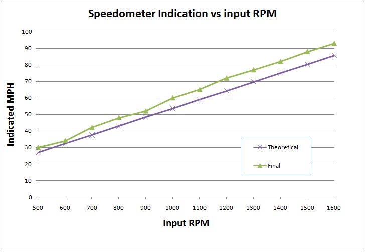
Then on to calibration. I took a deeper dive into calibration than with the tach, and it payed off.
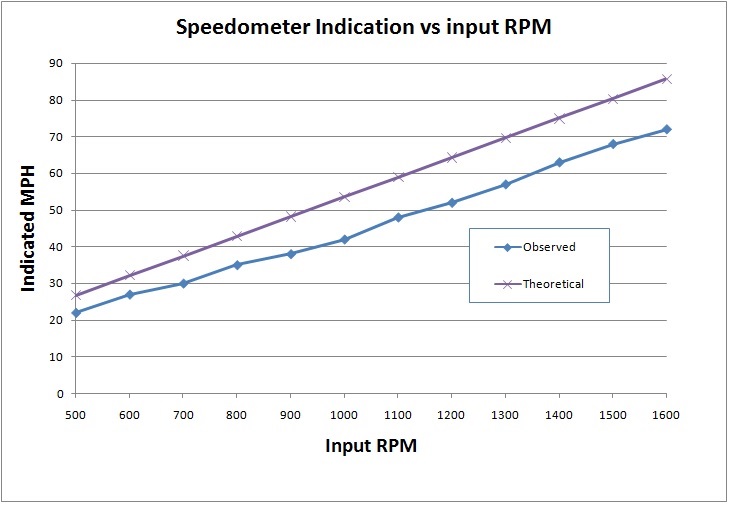
I
graphed the response curve for the instrument so I could compare it to
what it should be. Most speedos have a number on the face that
indicates how many revolutions of the cable should be needed to
register one mile on the odometer. A little thought will suggest
that this number is also the RPM of the cable that should register 60
MPH on the dial. In my speedo, this number was 1120. This
allowed me to generate the response line that the instrument should
have.
My speedo read nearly 20% low throughout its range.
Since the operation of the pointer was smooth and free, without catches
or oscillations, I thought I could rule out a mechanical problem, at least to start. A
weak 40-year old spring would probably make the readings high rather
than low. This left the magnet. Older magnet materials exhibit a
decline in magnetic strength with heat, shock, and just time. On the
theory that this was the causeof the error, I researched ways to
rejuvenate the magnet. This is mostly done with strong electromagnets,
sometimes using very high current pulses. All that is really neded,
though, is a relatively strong magnetic field to boost the strength of
the magnet.
I
have some pretty strong rare earth magnets, and in playing with them, I
learned something new about magnets: If you have two magnets, one a lot
stronger than the other, their like poles will not repel, they will
attract. This really confused me since I couldn't determine
which was the north and south poles of the speedo magnet by using a
strong magnet. It turns out that this is a known effect.
The strong magnet overwhelms the field of the weak magnet,
temporarily reversing its poles. Further, there can even be some
residual effect on the weak magnet.
After
this learning experience, I checked the speedo magnet with a compass
and found that the compass would react to the speedo magnet's north
pole, but not its south pole. It was as if the magnet didn't have
a south pole. Now, the physicists among us will tell us that this
is really unlikely, so probably I'd just displaced the south pole to
somewhere else on the magnet.
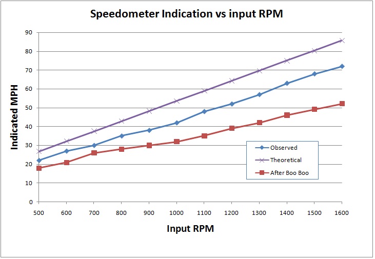
Fearing
that I'd ruined the magnet, I put the speedo back together and re-ran
the calibration check. I'd succeeded in making its performance a
lot worse. It was then reading almost 40% low.
Since
I at least learned that I could manipulate the strength of the magnet,
I thought if I designed the operation a little more intellegently, I
might be able to restore the magnet to its full strength. Knowing
from the compass which was the north pole of the magnet, I made a
strong magnet with known poles that would bridge the speedo magnet.
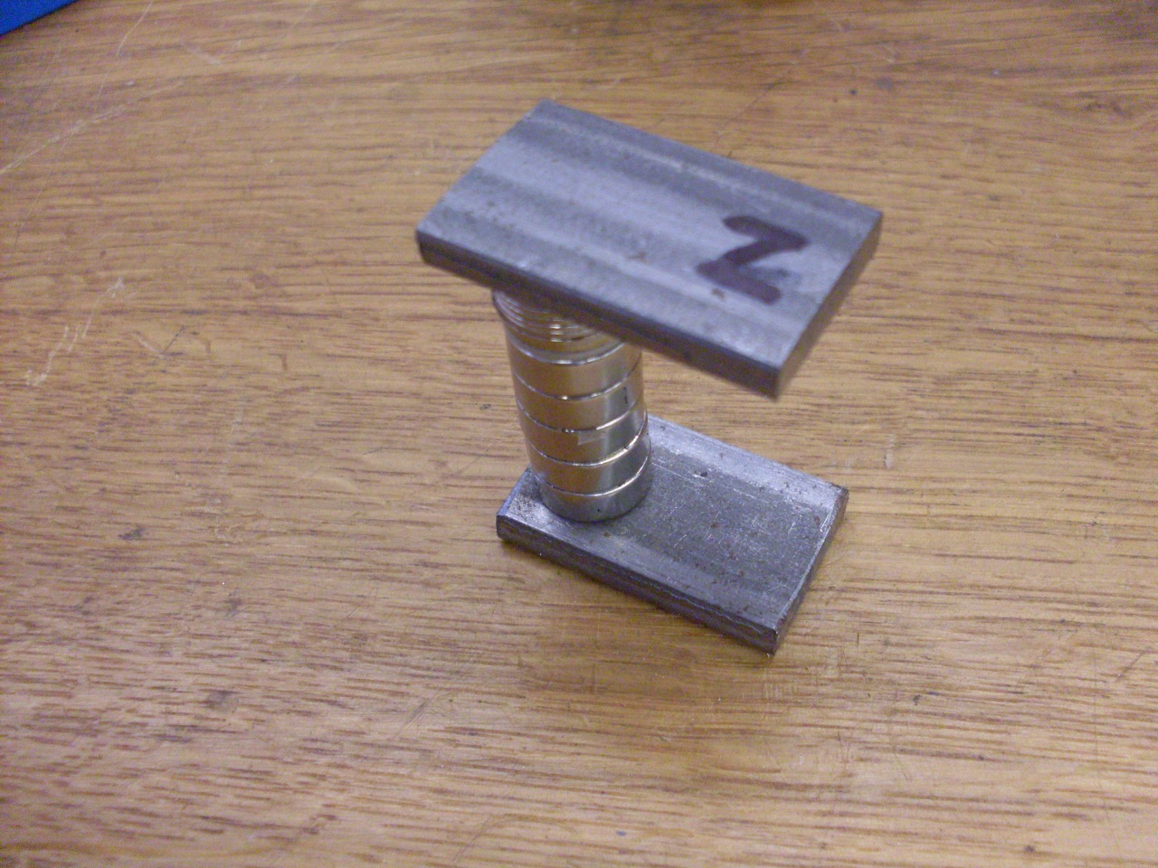
I
applied it to the speedo magnet, and stroked it back and forth for a
while. I really had no way to control or modulate the process,
but I surmised that when the magnets were originally made, they were
probably magnetized to saturation--that is, they were as strong as the
material would allow. If this was true, there wasn't much danger
of making the magnet much too strong.
Back
into the calibration fixture, and I was delighted to see that the
response line was now a little above the theoretical. The speedo
now read a little high, which I believe was the way most speedometers
were in new cars.
This is the way I'll leave it, and I'll re-open the tach to take care of its low readings.
I
did all the calibration without the odometer pawl in place, so none of
it registered on the odometers. I installed the pawl and keepers,
and then ran it in the cal setup to make sure the odometers worked OK.
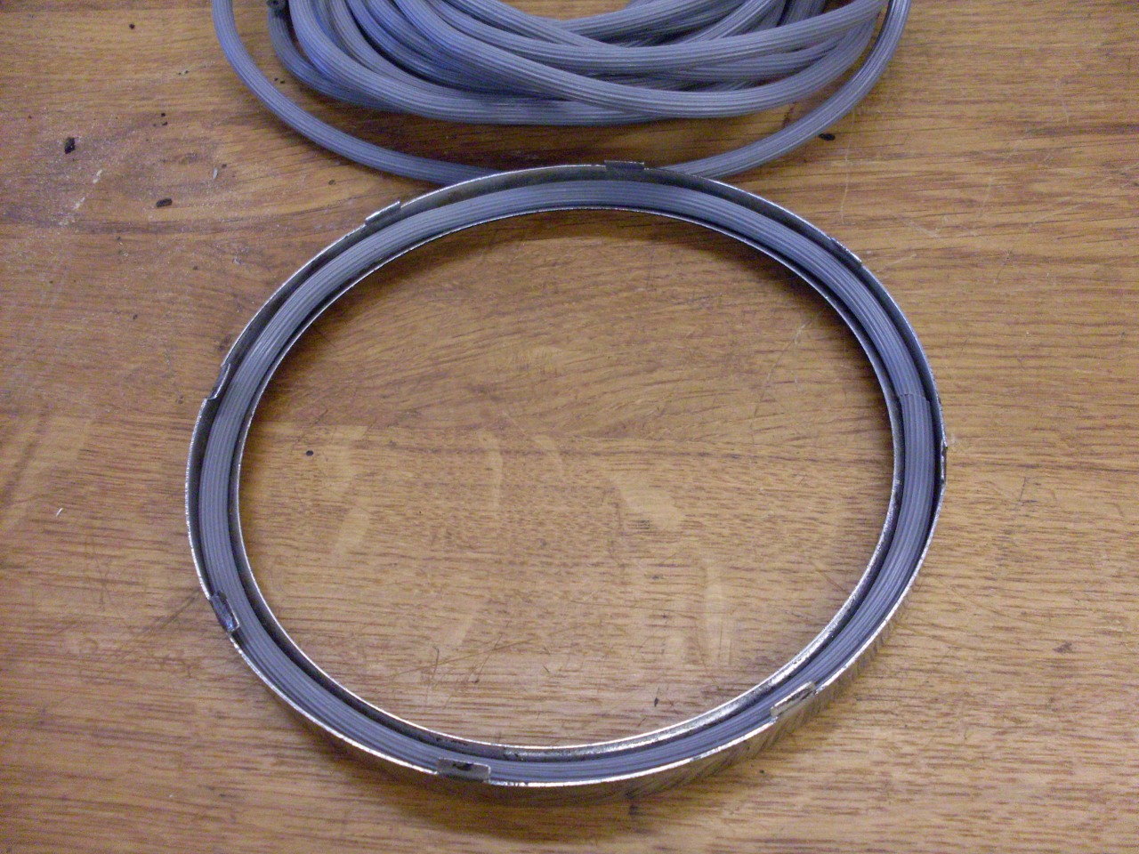
Ready to go back in the case. I use a rubber cord to seal the bezel to the glass.

Ready to go into the dash.
Comments to: elhollin1@yahoo.com
To my other TR6 pages