To my other TR6 pages
September 1, 2014
Rear Suspension
The
TR6, like some of its ancestors, has an independent rear suspension
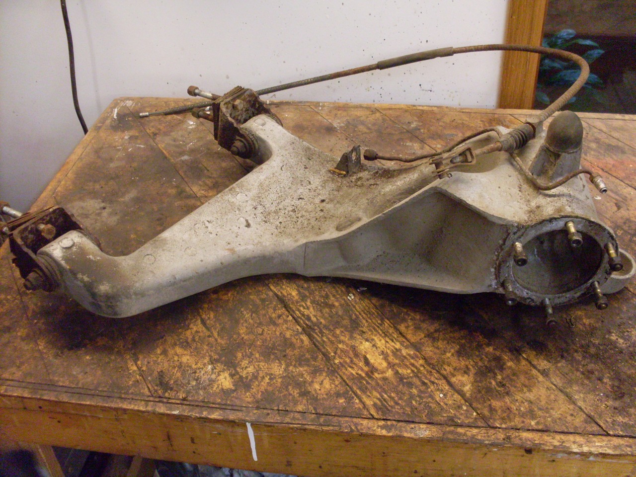
using semi-trailing arms. The arms are largish aluminum
castings that carry, in addition to the wheel hubs and brake backing
plates, a recess for the coil springs, and a bracket for a link to
the lever arm shock absorbers.
My trailing arms were dirty, but otherwise in good shape.
The
trailing arms pivot on brackets mounted to the frame. The factory
rubber bushings can be a chore to remove, but a little shop built
persuader helps a lot. I found that running a 3/16 drill bit into
the rubber through the bushing all the way around made it even
easier. There was some corrosion in the bores, but after
cleaning it out they still measured within spec.

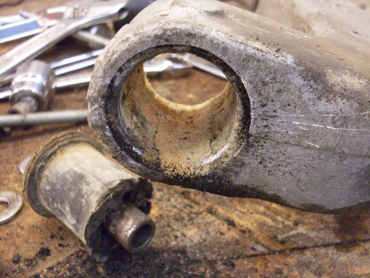
Brackets and bushings removed, ready for cleanup. Also all the rubber bushes and plugs removed from the arms.


I'd
read in multiple sources that the studs that mount the hub to the
trailing arms are prone to stripping. This wouldn't be unexpected
for fairly shallow fine threads in aluminum. A very common fix
(or preventative) is to install thread inserts into these holes.
The threads in my arms all appeared to be fine, but there is no
better time to install an ounce of prevention than when everything is
apart anyway. I decided to proactively upgrade the threads with
Helicoil type inserts.
One often discussed challenge to
installing inserts in the trailing arms is that the arms are such a
large and odd shape, they are just about impossible to mount on a drill
press, and a potential danger of drilling by hand is getting a crooked
hole. I really believe this threat is a little overblown.
There is a straight hole already there, and it only needs to be
enlarged a little, and then tapped. The larger drill bit will try
to follow the original hole, and anyone who has handled a hand drill
before will know how to let it find the path of least resistance.
Likewise with the tap--it wants to go straight down the hole, and
will only go off track if there is some outside force deflecting it.
On
the other hand, these trailing arms are not cheap if they need to be
replaced due to some unforseen problem in drilling or tapping, so some
kind of insurance seemed like a good idea. There are some
guide jigs available commercially to help with this, but they
aren't cheap. If buying the jig were the only option, I'd
probably just do it by hand, and be pretty sure it would come out
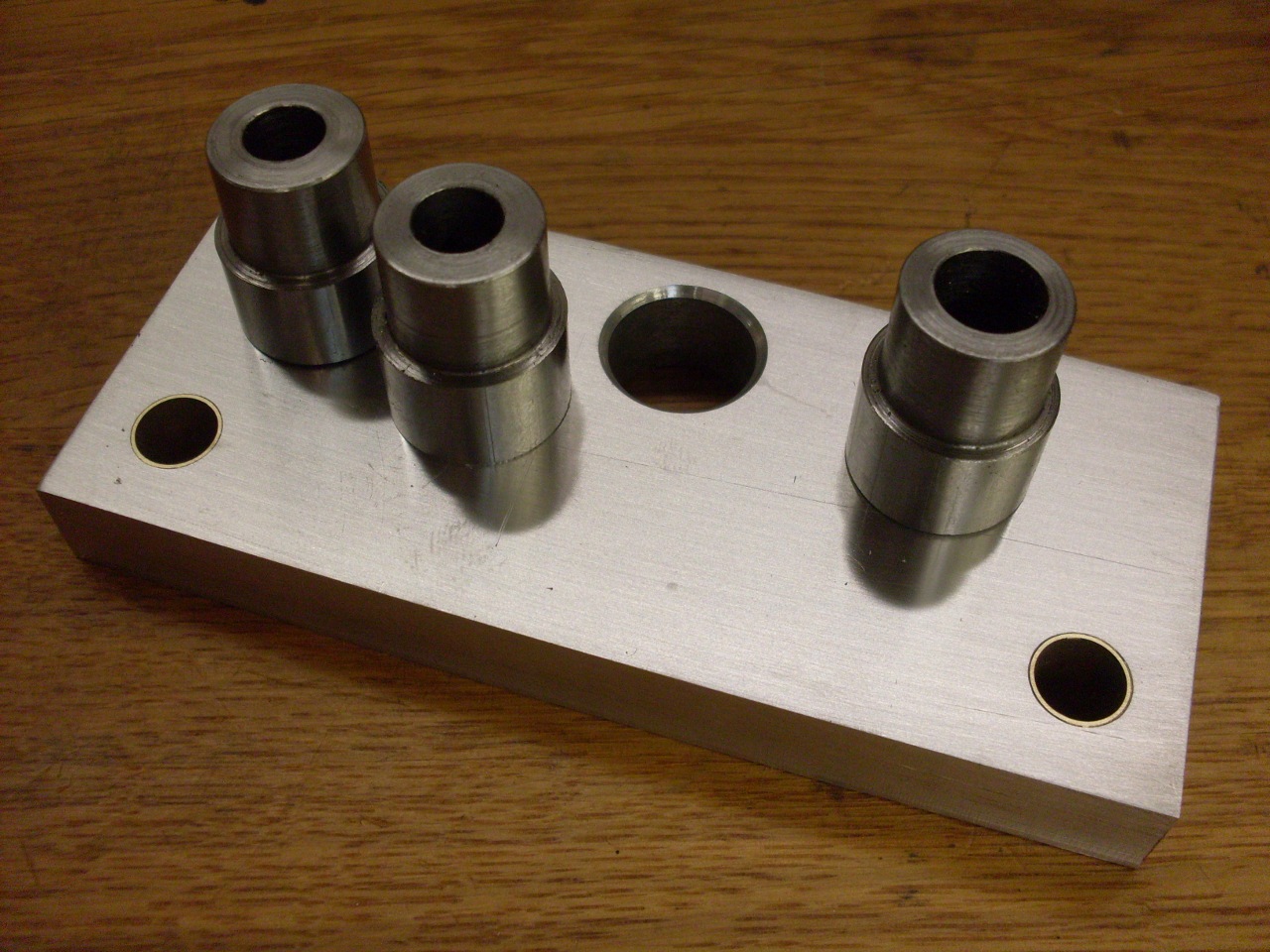
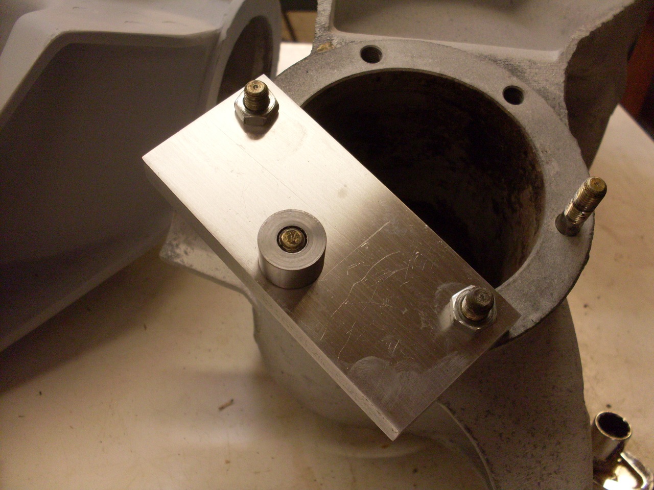
fine. In the end I made my own small dril/tap guide. Unlike
at least one commercial offering, mine only guides one hole at a time,
mainly because I wasn't willing to devote a larger piece of stock to
it. Ther jig consists of an aluminum carrier block and three
steel guide bushes--one to go over an original stud to center the jig,
one for the drill, and one for the tap.
I chose to stay with 5/16" studs, but to install inserts for course threads instead of fine.
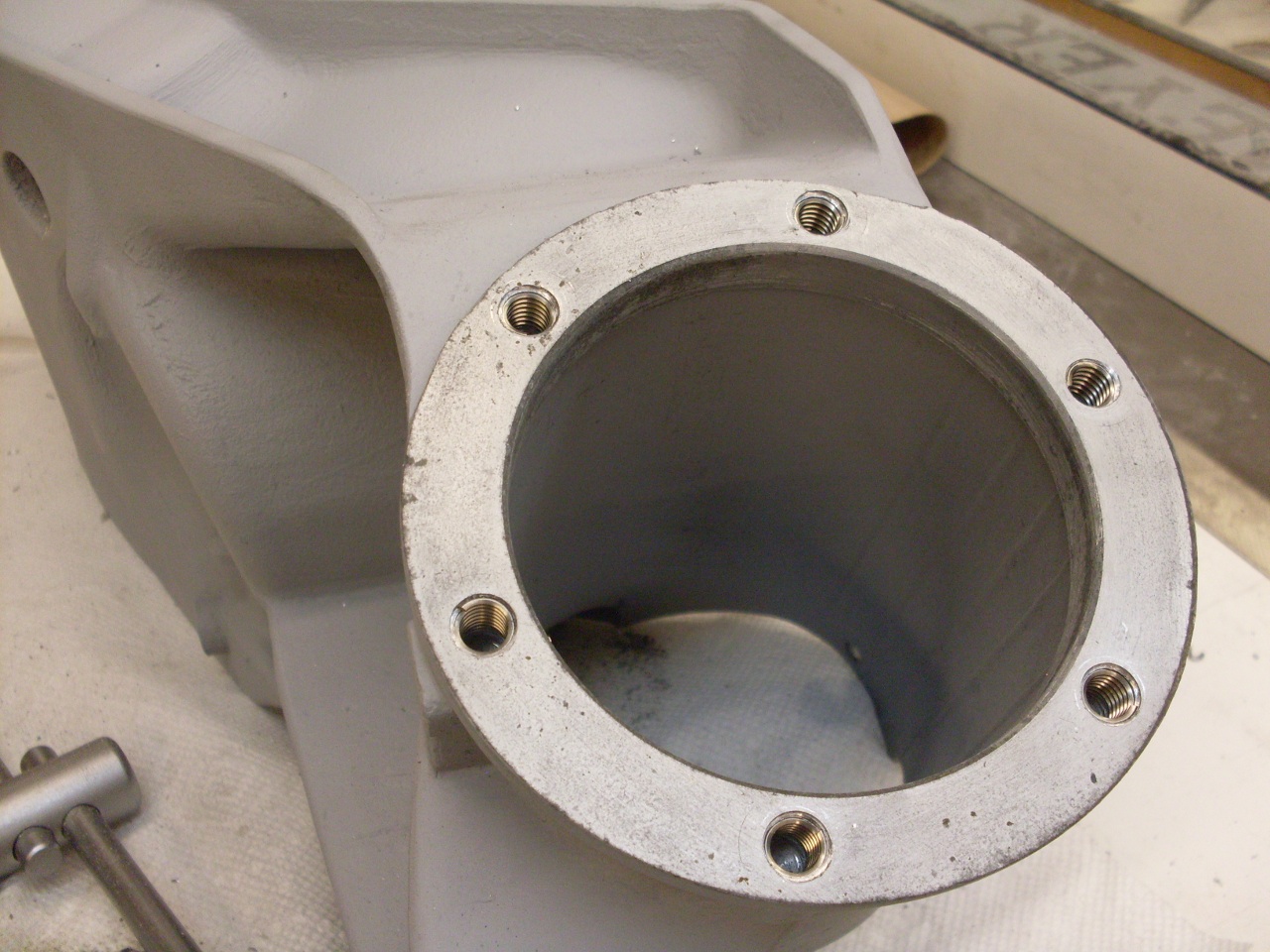
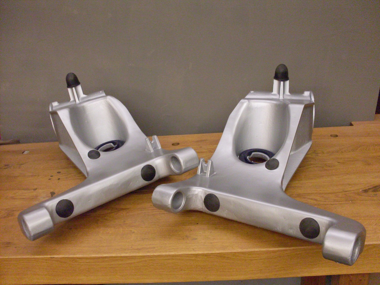
Here are the trailing arms, cleaned up, painted, and plugged.
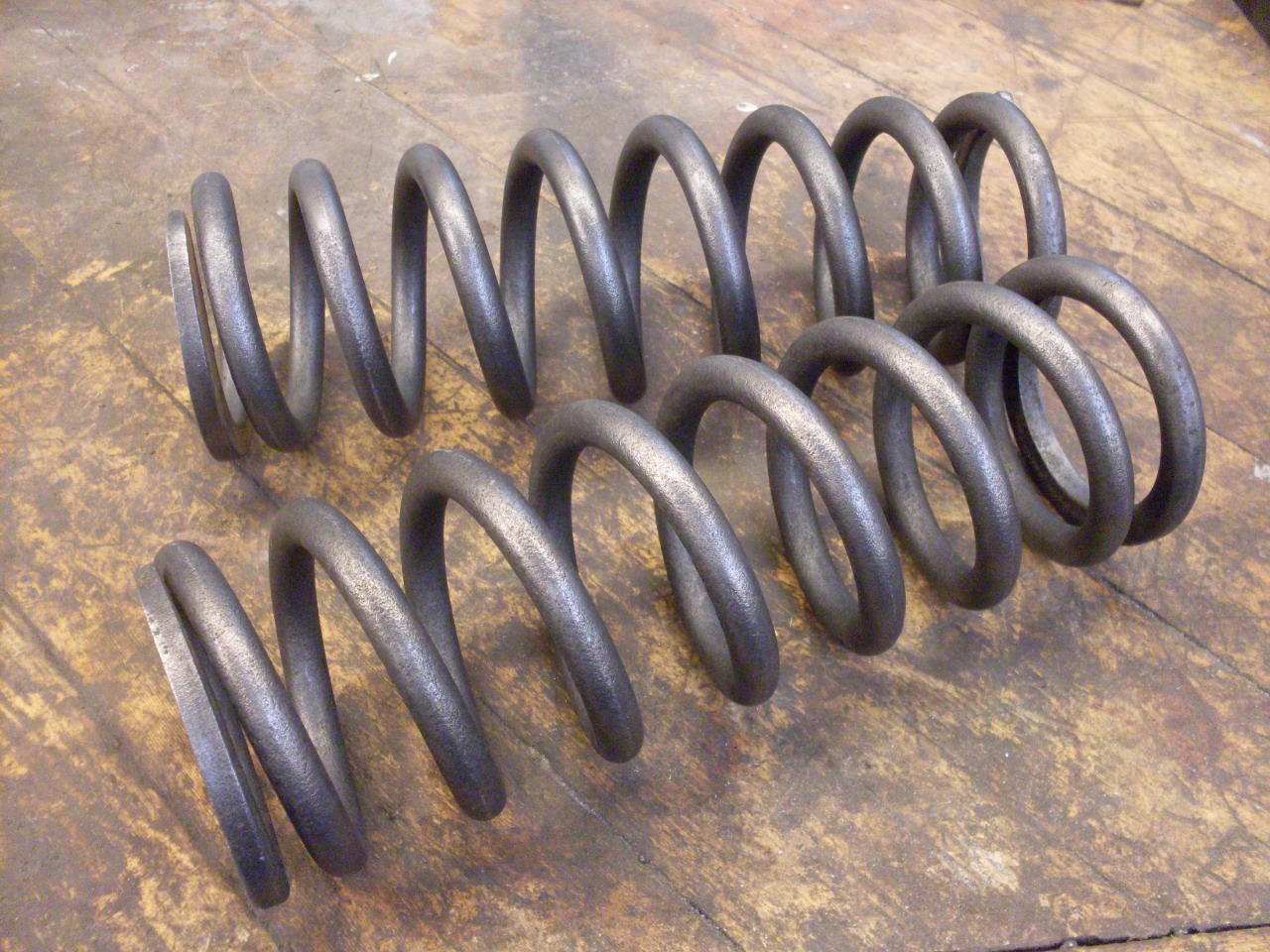
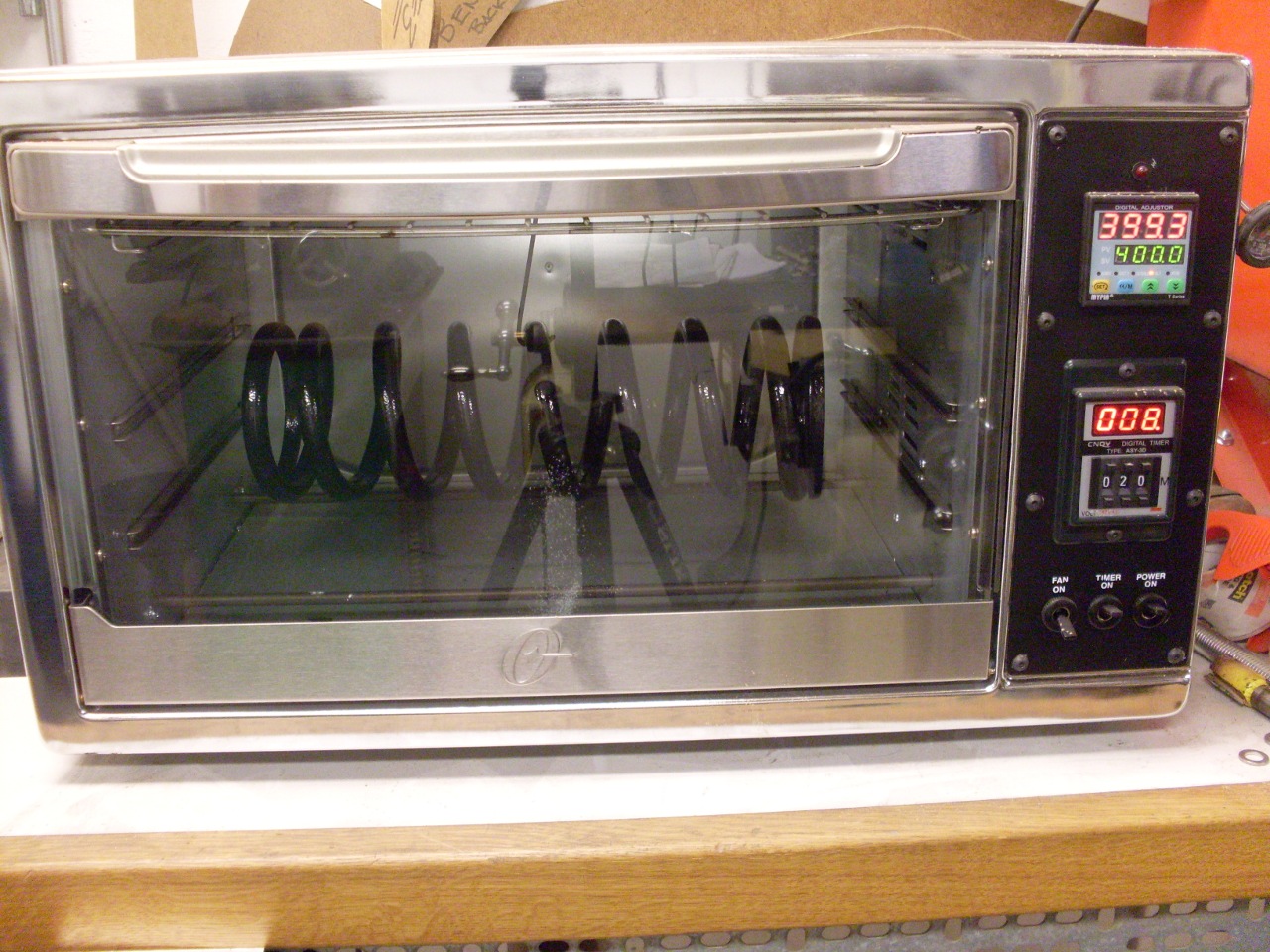
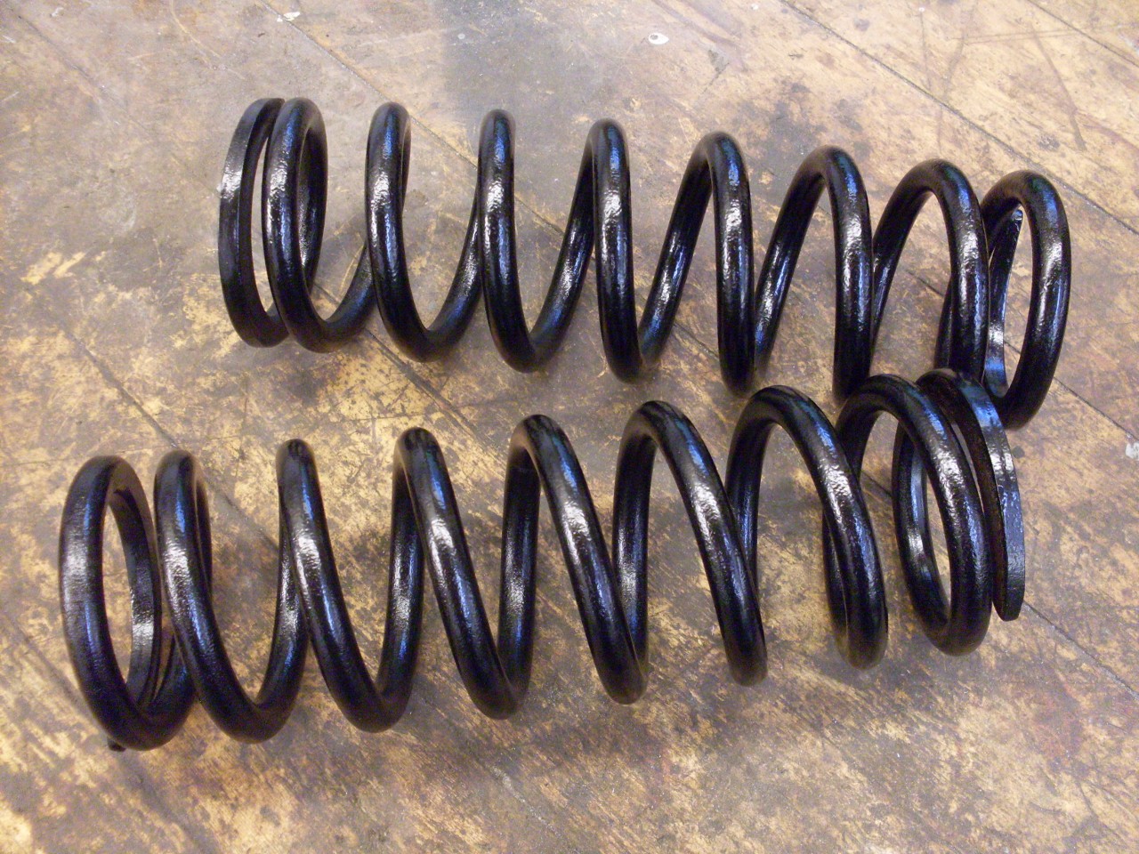
The
springs measured a little longer than the spec allows. After a
quick query on one of the forums, it appears that everyone's
springs are longer than spec, so I didn't worry about it. The
pics show the springs after derusting, in the powder coat oven, and
ready to install.
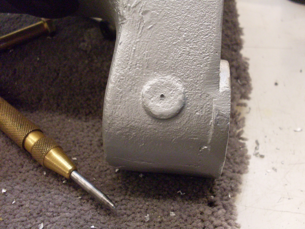
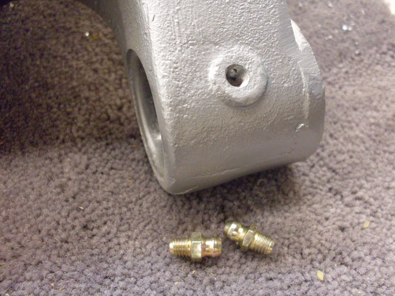
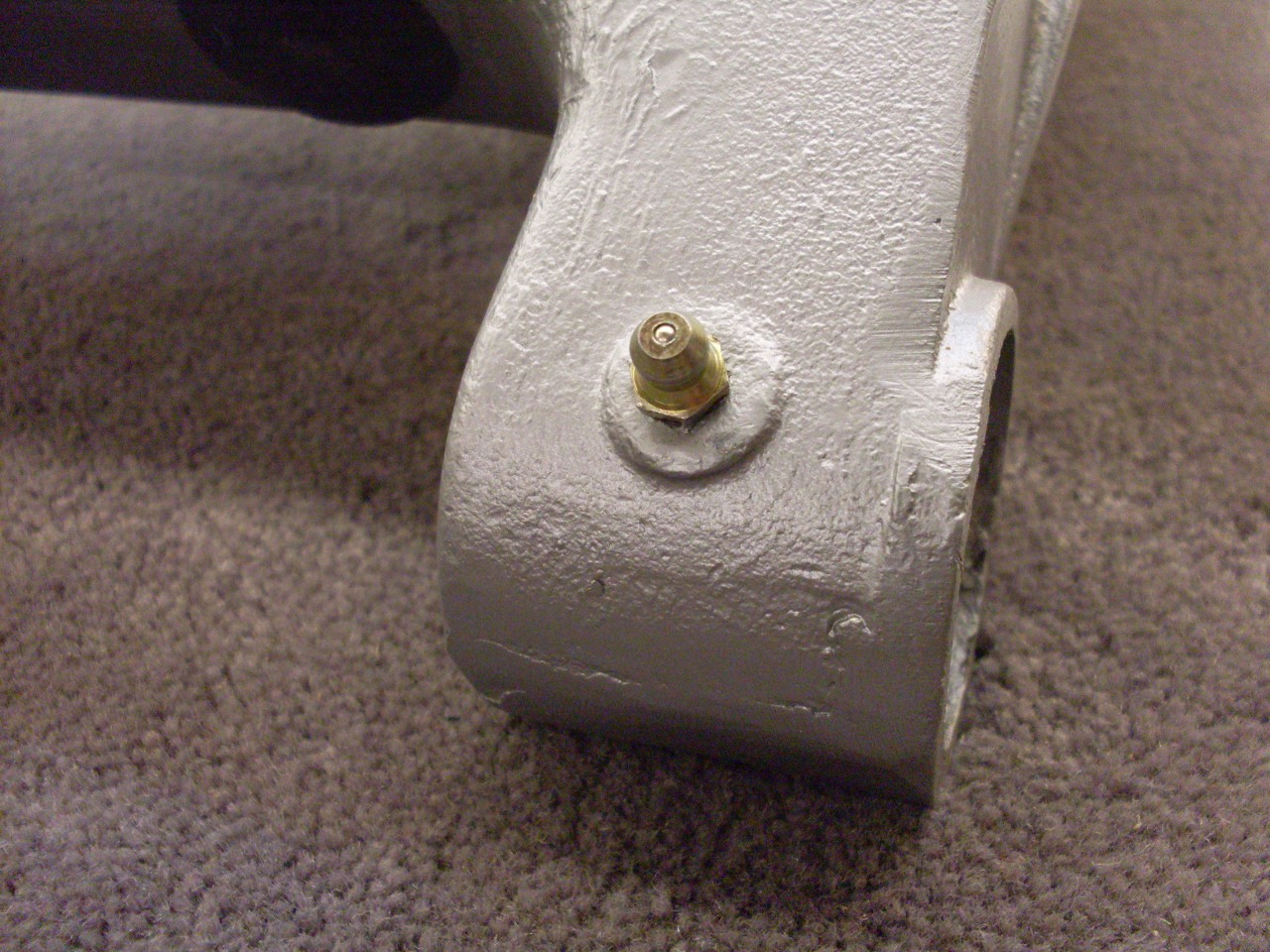
I
planned on using urethane bushes in the trailing arms as opposed to the
original rubber, mainly for longevity. Since urethane bushes,
unlike rubber, need lubrication, I installed grease zerks on the bottom
side of the bush bore. There is already a nice land there in the
casting, as if it was an option the factory wanted to leave open.
Now
comes the interesting part. The original design of the TR6
rear suspension didn't provide any means to adjust wheel camber.
A number of enthusiasts have devised schemes to correct this
omission, and there is at least one popular aftermarket product that
addresses it. A quick look at some of the geometry of the
trailing arm mounting points can help illustrate the challenge of
camber adjustment.
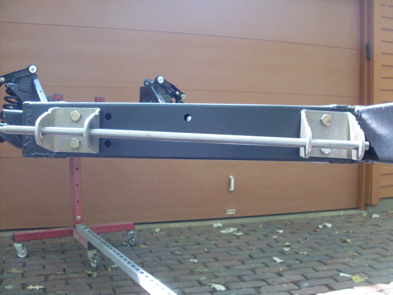
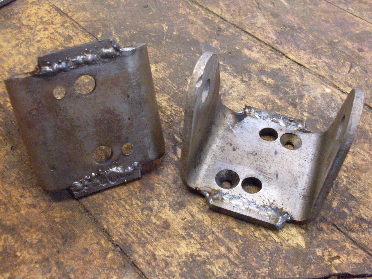
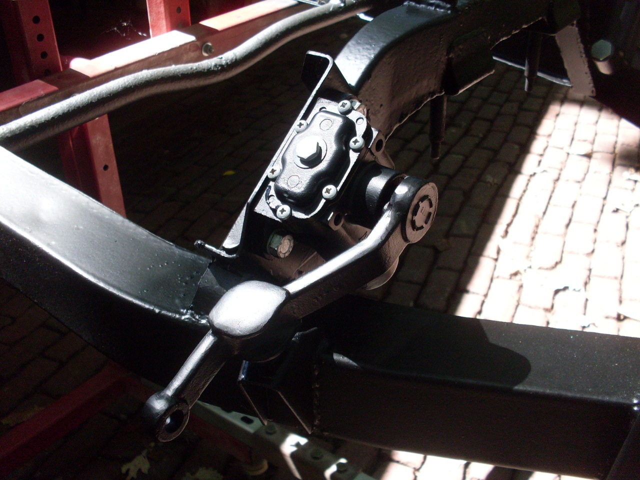
The inner and outer brackets that hold the
trailing arm are different parts. The main difference is the
height of the pivot pin holes relative to the frame attachment points.
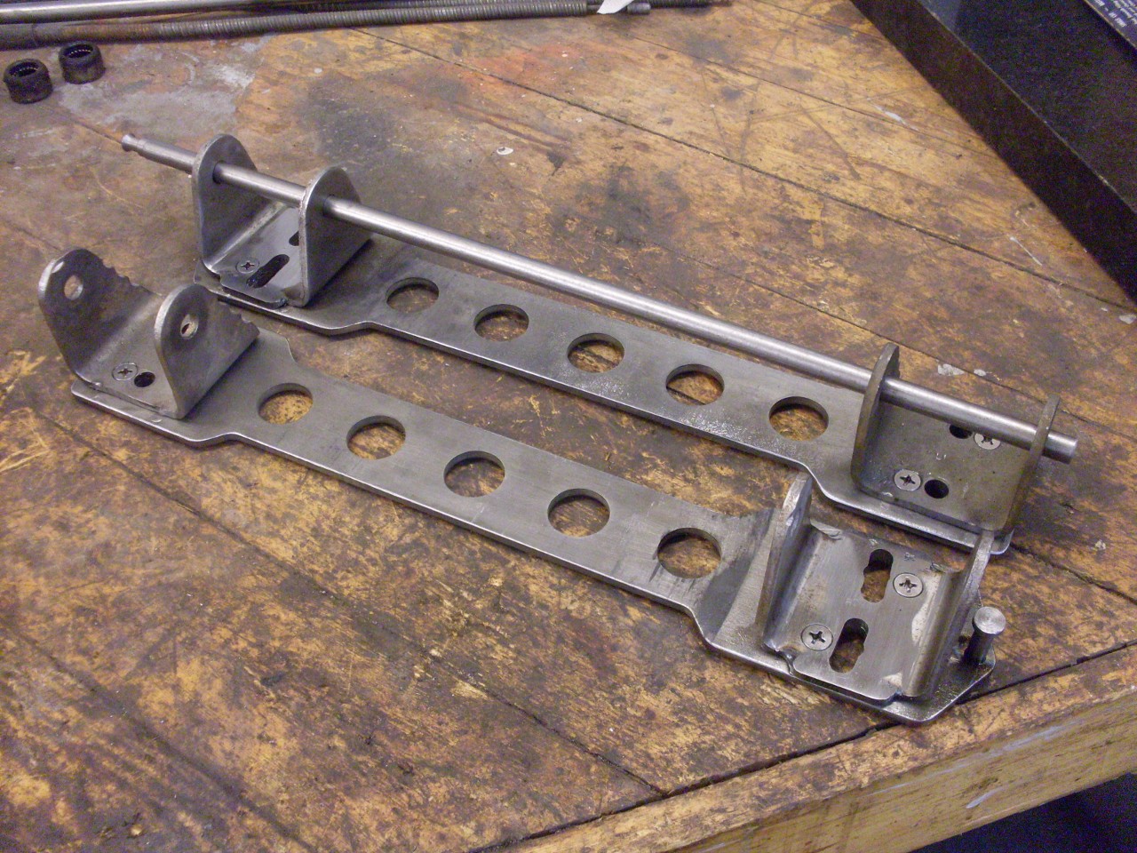
This pic shows a 7/16 rod run through the pivot bolt holes in the
two stock brackets. It is easy to see that the rod is not
parallel to the plane of the chassis rails. A close look will
also reveal that both brackets are slightly cocked to the right to
allow the pivot bolt holes to all be colinear. There is just
enough slop in the frame and bracket holes to allow this.
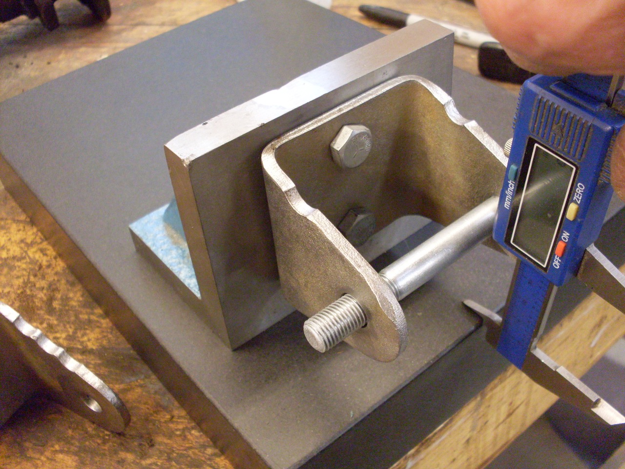
Measurig
the difference in height of the pivot pins and applying a little trig,
we find that the pivot angle is about 1.8 degrees relative to the
plane of the chassis members. One way to change the wheel
camber is to adjust this angle.
There is a very nice analysis of camber geometry and a method for adjusting it at the Buckeye Triumph
site. The method involves swapping out brackets with different
pivot heights. While I'm sure this approach can be very
effective, swapping brackets is a pretty time consuming task, and
finding the right combination might take several iterations.
There
is also a product available that includes brackets with pivot pins
that can be adjusted vertically to give a range of angles. The
product is popular, and many users endorse it, so I assume it works
adequately. I consider it pretty pricey, though, and it does have
a few quirks that give me at least a little pause. For one, I'm
not sure if the brackets can provide the colinerarity of the pivot pins
through the entire range of adjustment. That is, with one bracket
pin higher than the other, will they be colinear? If not, it
appears that the pivot bolt must be cocked a little inside at least one
of the bushings. If the pins are colinear, then it looks like the
pins must be cocked a little in the brackets, which could affect how
well the bolt holds. I should say that I have not examined these
brackets up close, so it is possible that these things are addressed in
ways I'm not aware of.
In the end, I decided to make up an experimental adjustment system that soothes my worries.
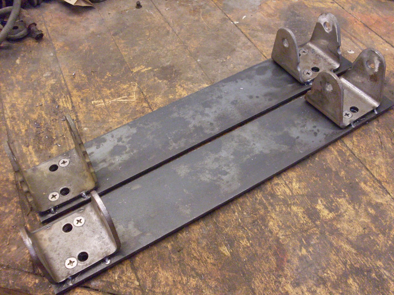
I
got a couple of pieces of 3/16 x 3" steel, and cut them a little
shorter than the trailing arm mounting members on the frame.
These serve as a carrier plate that the trailing arm brackets
will attach to. With the 7/16 rod on place to keep the brackets
lined up, and the carrier plate drilled to allow the bracket mounting
bolts through, I tack welded the brackets to the carrier.
Then
I drilled, tapped the carrier, and countersunk the brackets for flat
head screwas to hold the brackets on the carrier in the aligned
position. I then ground away the tack welds so the brackets and
carrier could be separated.
I
had to weld little extensions to the outboard brackets to allow a
larger adjustment range. It might have been easier just to make
new brackets.
Then
the mounting holes in the carrier plate and outboard brackets were
milled to a short arc centered on the lower inboard mounting hole.
The carriers were also shaped and lightened a little. The
idea here is that the carrier, along with the brackets, can rotate a
few detgrees around the lower inboard mounting hole, but since the
brackets are fixed to the carrier, the alignment of the trailing
arm pivot holes remains constant. The upper inboard mounting hole
also has to be elongated slightly. There is also a little
adjustment pin welded in at the far outboard end of the carrier.
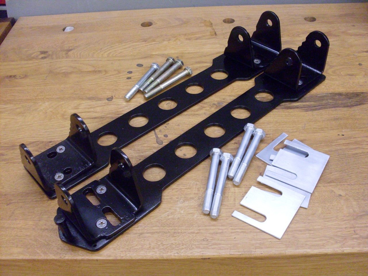
Everything
was then powder coated or plated. All four of my trailing arm
brackets had four shims from the factory. The new carrier does
the job of three of them, so I still needed to install one shim.
The shim also proivided a little space between the carrier and
the frame member.
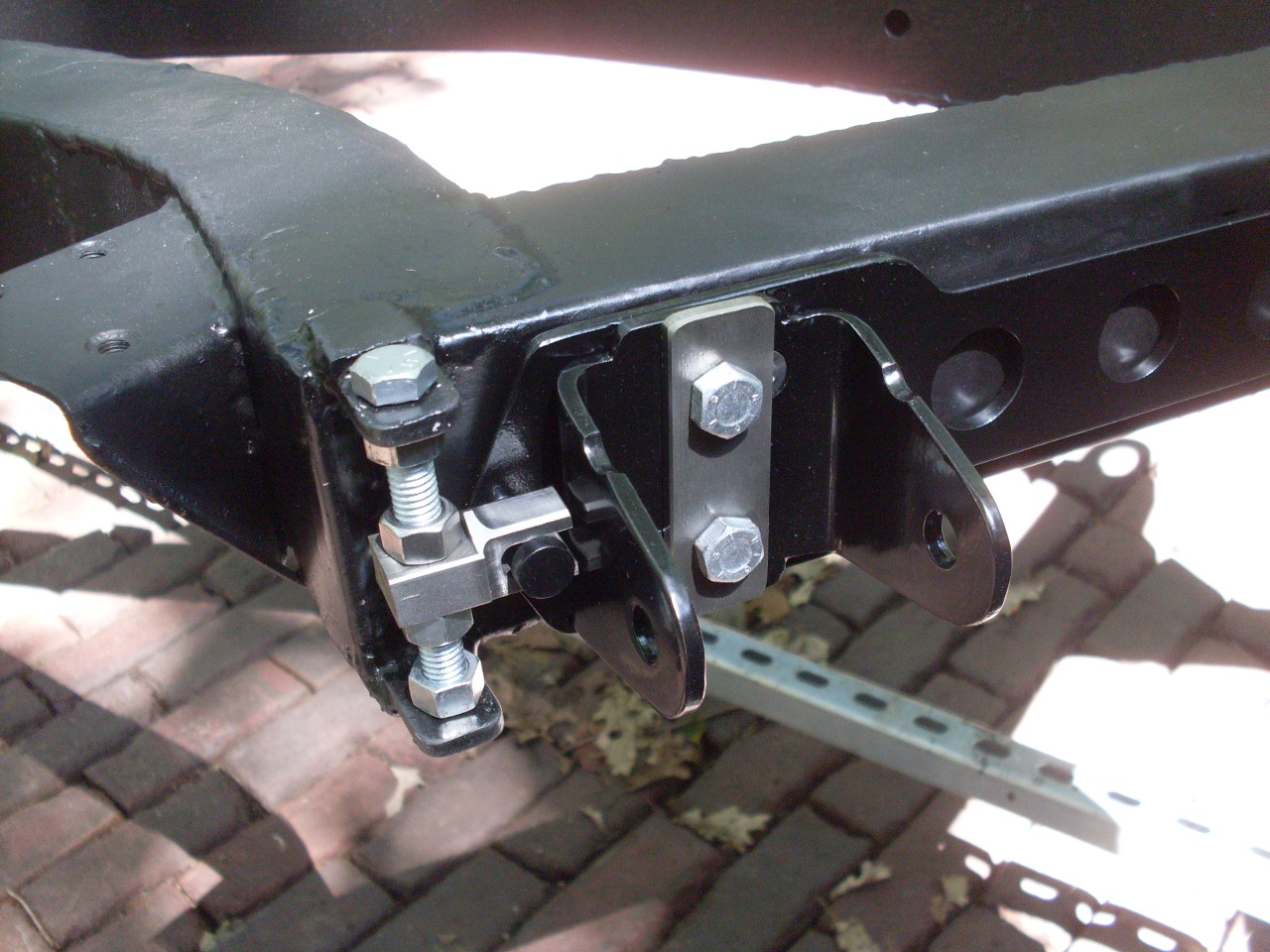
For an adjustment mechanism, I welded two little ears to the frame at the ends of the trailing arm mounting members.
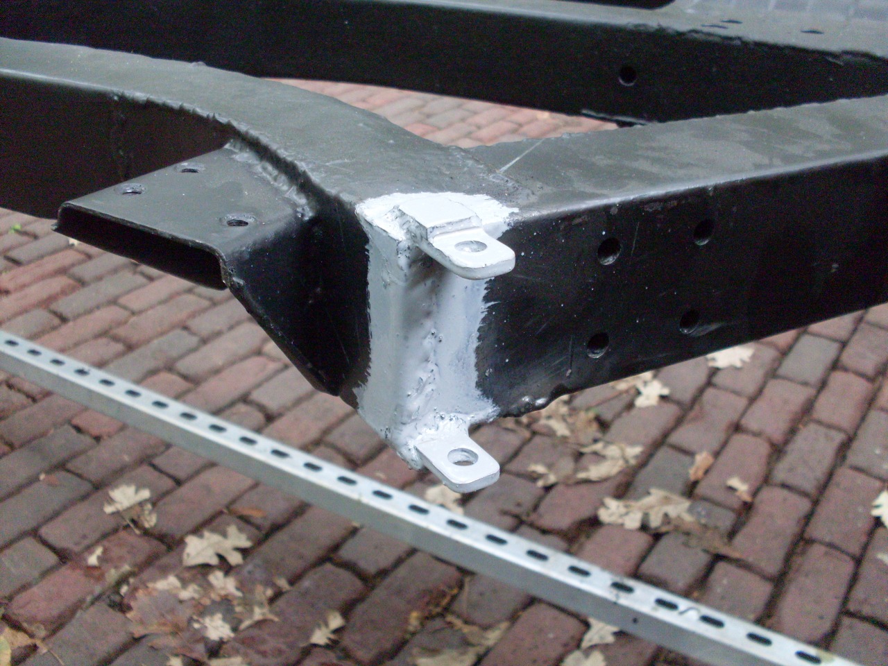
The
adjustment mechanism itself is just a long bolt, held in place at each
end. There is a little stainlesss block that can be moved up and
down the bolt with a nut above and below. The block engages the
pin at the end of the carrier plate.
With
the parts of the experimental gizmo finiished, I had to turn to the
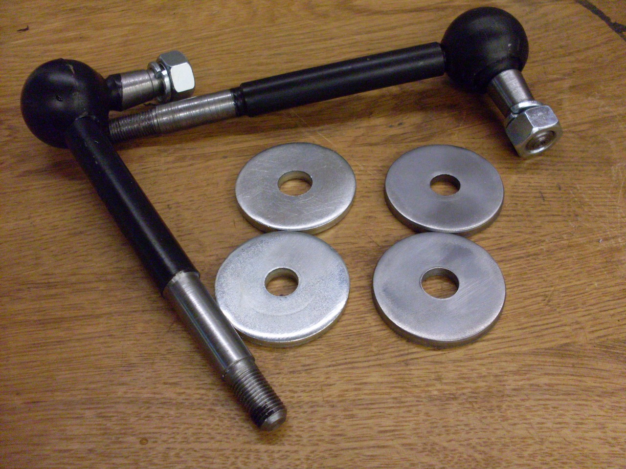
other pieces of the rear suspension. The shock links are an
integral part of the suspension. They hold the rear end of the
trailing arm up. I noticed on the two links I bought that one had
zinc plated washers, the other had plain washers. The difference
can just be seen in the picture, but it was a lot more obvious in
person. I get a little tired of being the suppliers' QA
department.
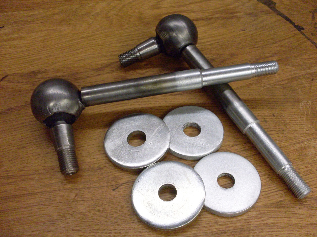
Also
the paint was pretty pathetic on the links--it would easily scratch off
with a fingernail. In a few steps that I admit might be a little
anal, I stripped the paint (it didn't take much), plated the lower
parts of the links, and painted with real primer and paint.

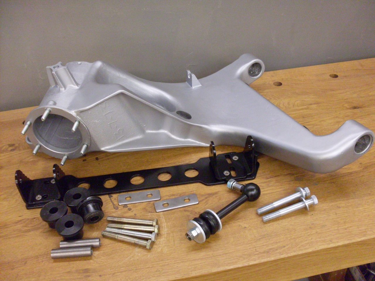
So here are most of the parts for the suspension.
Mounted the lever shocks.
A cargo strap worked OK as a spring compressor.

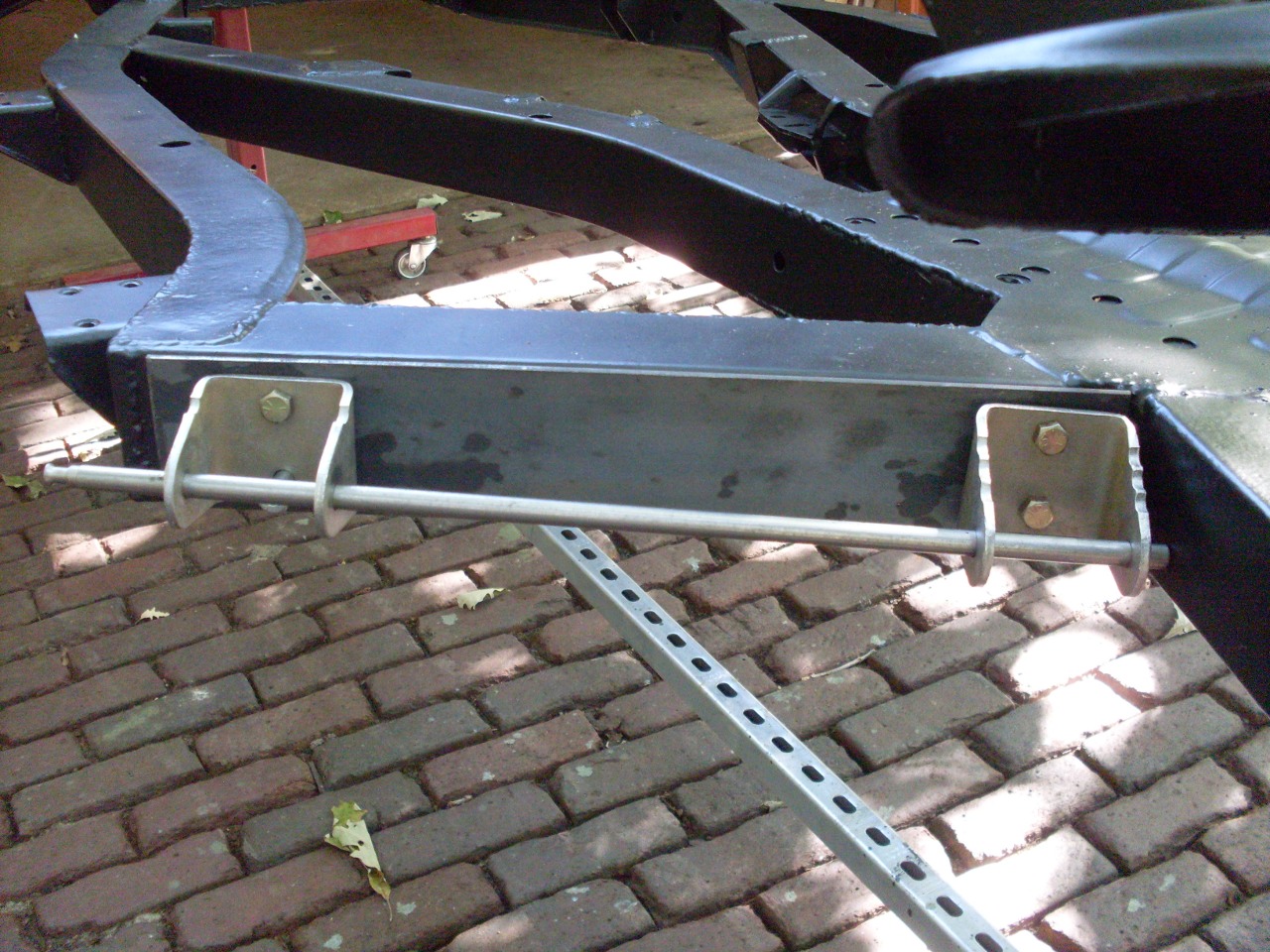
On the frame. I used a nice hefty stainless washer plate to bridge the arced holes.
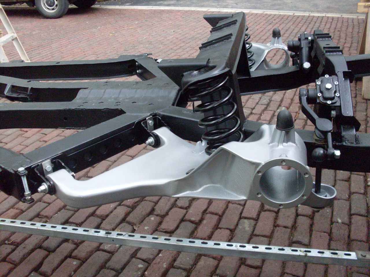
A
closer view of the camber adjuster. I've got it set in the
middle--about what the stock brackets would give--until the suspension
is fully loaded.

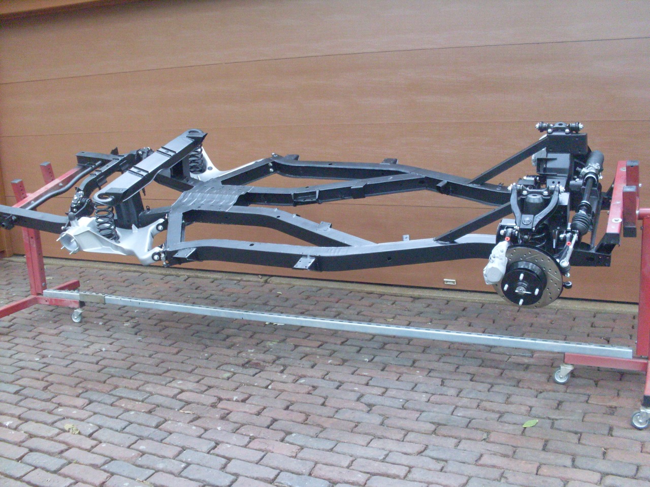
Getting impatient to get this thing on its own feet.
Comments to: elhollin1@yahoo.com
To my other TR6 pages