To my other TR6 pages
August 11, 2014
Rear Lever Shocks
[Click the pics for a better view]
In anticipation of assembling the rear suspension soon, I dug out the rear shocks.
The
TR6, like many British cars of the era, used Armstrong lever type
dampers (shock absorbers to us Americans). These units use two
adjacent cylinders with pistons that move in a see-saw fashion
controlled by the lever arm, which is in turn attached to the trailing
arm of the rear suspension. Hydraulic oil is pumped back and
forth between the cylinders, but is restricted by a metering valve.
The metering valve is seperately adjustable for each direction of
oil flow, thus allowing for independent setting of damping stiffness
for jounce (bump) and rebound motions.
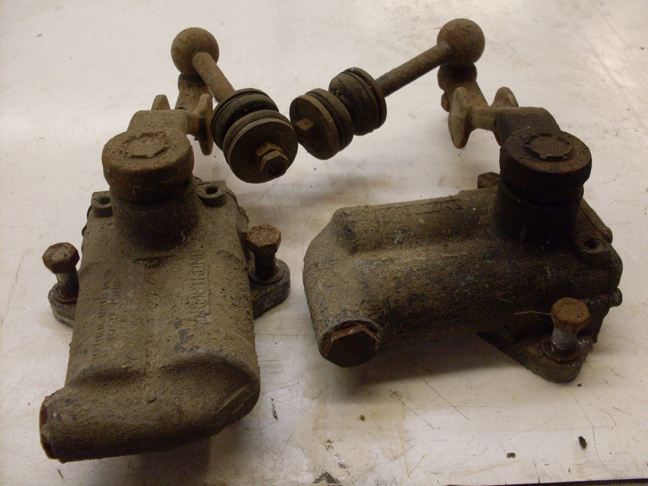
The
shocks were grimy and dirt-caked, but the main thing I was looking for
initially is evidence of leaking from around the lever arm shaft.
I didn't really see any, but I delayed any celebration until I
could look at them more closely. There was no doubt that the links were deceased, though.
After
some
cleanup and bead blasting, I checked out the action of the lever
arms. Firm but smooth motion throughout the 90 degree arc of the
arms told me that these units might just be serviceable. The
units may not be originals, but early 80s replacements. If so,
they didn't have many miles on them. When I removed the caps, I
was really happy to find both shocks still filled to the top with oil.
Though
these shocks are not considered DIY repairable, I was prepared to give
it a try anyway if necessary. A typical failure mode is leaking
around the arm shaft, which apparently has a rudimentary bearing and no
real seal. Commercial rebuilders often machine the body to accept
a better bearing and a true oil seal, which is what I would have
attempted. This was moot, though, since the shocks apparently
didn't need any repairs.
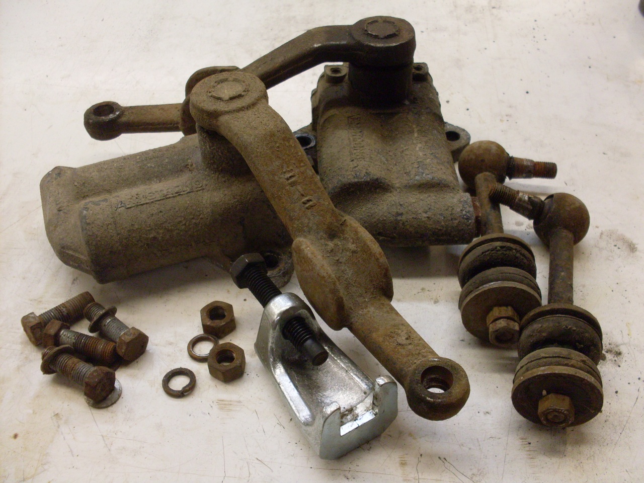
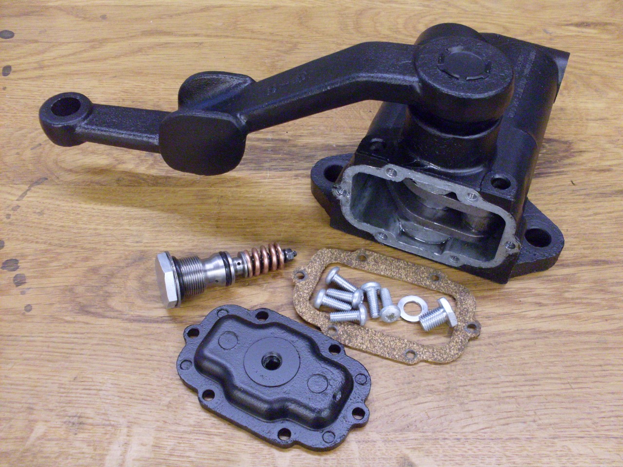
I
did decide to flush out the units and replace the 30+ year old oil with
fresh fluid. It would also make sense to replace a few rubber
parts along the way. The fluid gets drained by removing the body
cap and the valve assembly and pumping the arm over a catch basin.
The body caps get a routine linishing to maks sure they are flat.
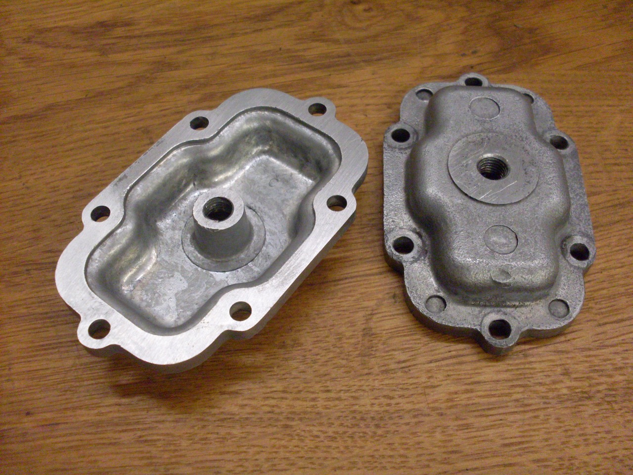
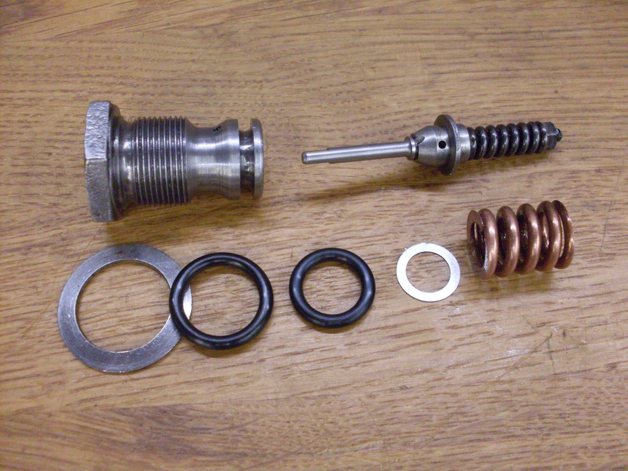
The
valve assembly has two O rings--a smaller one to make sure the flow
from one cylinder and the other goes through the valve and not around
it, and a larger one to seal the valve assembly in the body. The
O rings are industrial sizes -111 and -113, respectively. I
didn't do any adjustment of the valve at this point, but if I had, the
jounce damping is controlled by the shims under the large copper
colored spring. while rebound stiffness is set by turning the nut at
the top of the smaller, longer spring. The pic shows the assembly
with new O rings. The one shim was from the factory. This
must vary, since the valve on the other side didn't have any shims.
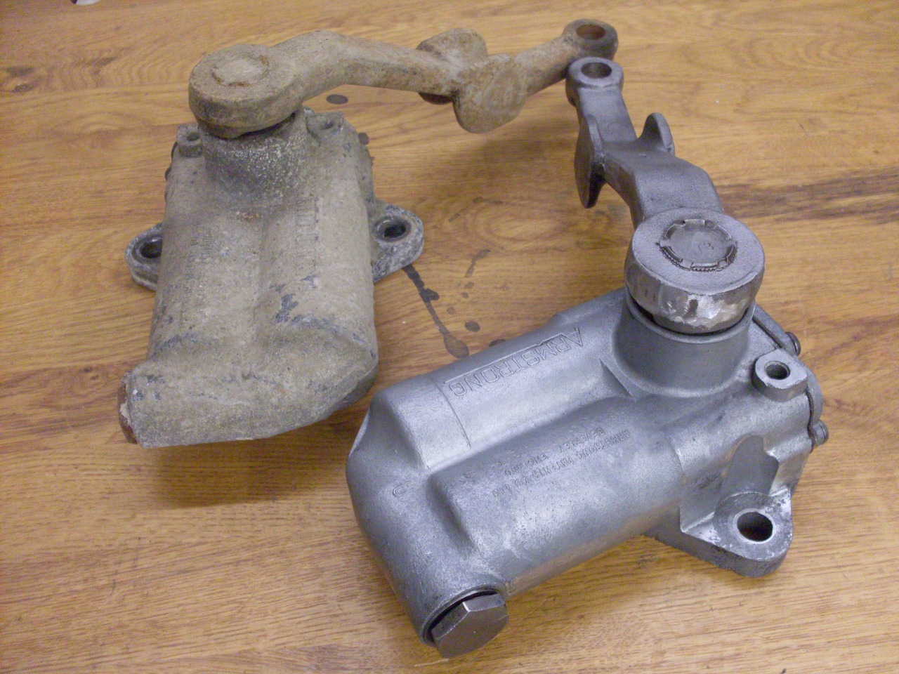
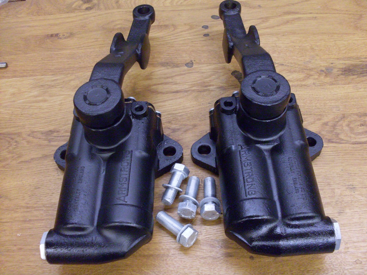
After
draining, and flushing a few times with mineral spirits, I primed and
painted the bodies, replated the hardware, and made new cork gaskets
for the body caps.
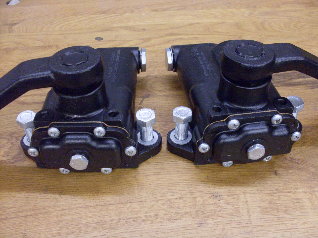
These are the units ready for refilling.
I
found the quickest way to refill the shocks is to fill the cylinders
first through the valve cavity. With the shock mounted sideways
and the valve removed, oil is put into the valve cavity, and the arm
pumped. This is repeated until the level of oil in the cavity
doesn't fall with movement of the arm, and no more bubbles are seen.
The movement of oil from one cylinder to the other can be plainly
seen in the cavity. The valve assembly is then inserted and
tightened.
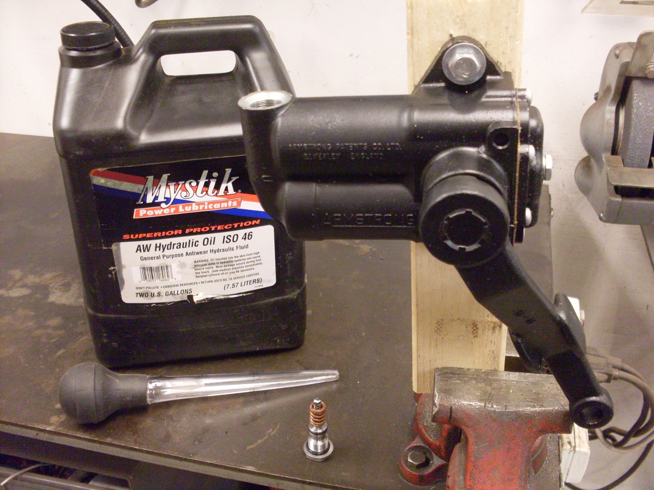
Lastly, the reservoir is filled.

Now it's on the shelf for these dudes until I need them for the rear suspension build.
Comments to: elhollin1@yahoo.com
To my other TR6 pages