To my other TR6 pages
January 22, 2018
Battery System
With the wrap up of the wiring,
the only piece of the electrical system left to do was the battery and
its associated parts. I didn't think there was much to change in
the battery system untill I got down to some of the details.
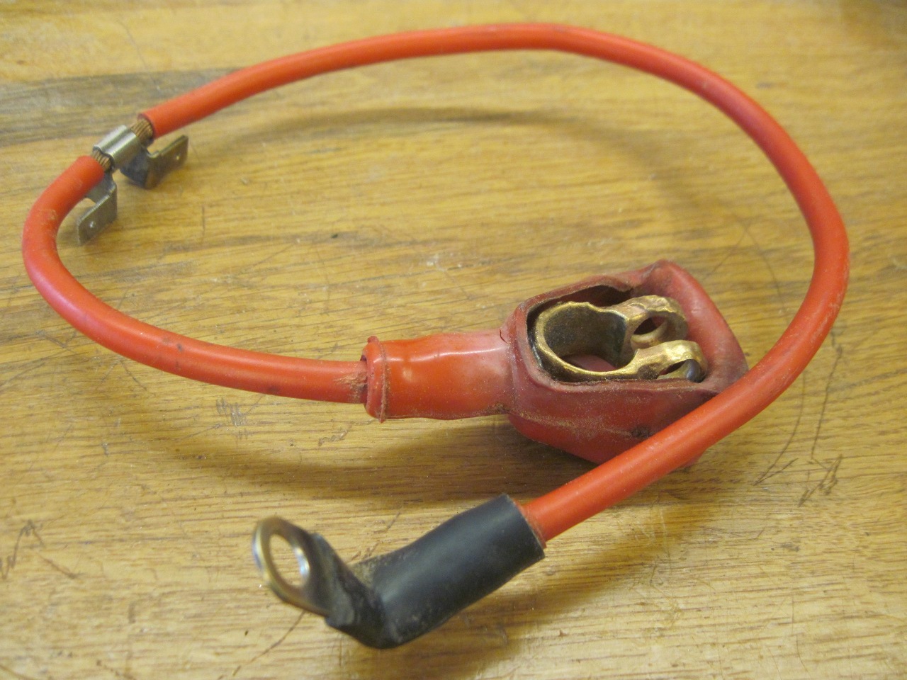
First,
I dug out the battery cables. The positive cable looks to be
about 6 gauge wire with a crimped tap along its length with four spade
connectors. This is where the alternator connects to the battery, and
where all of the electrical loads except the starter source their
power. The battery terminal connector was roughly cast or forged
brass or bronze.
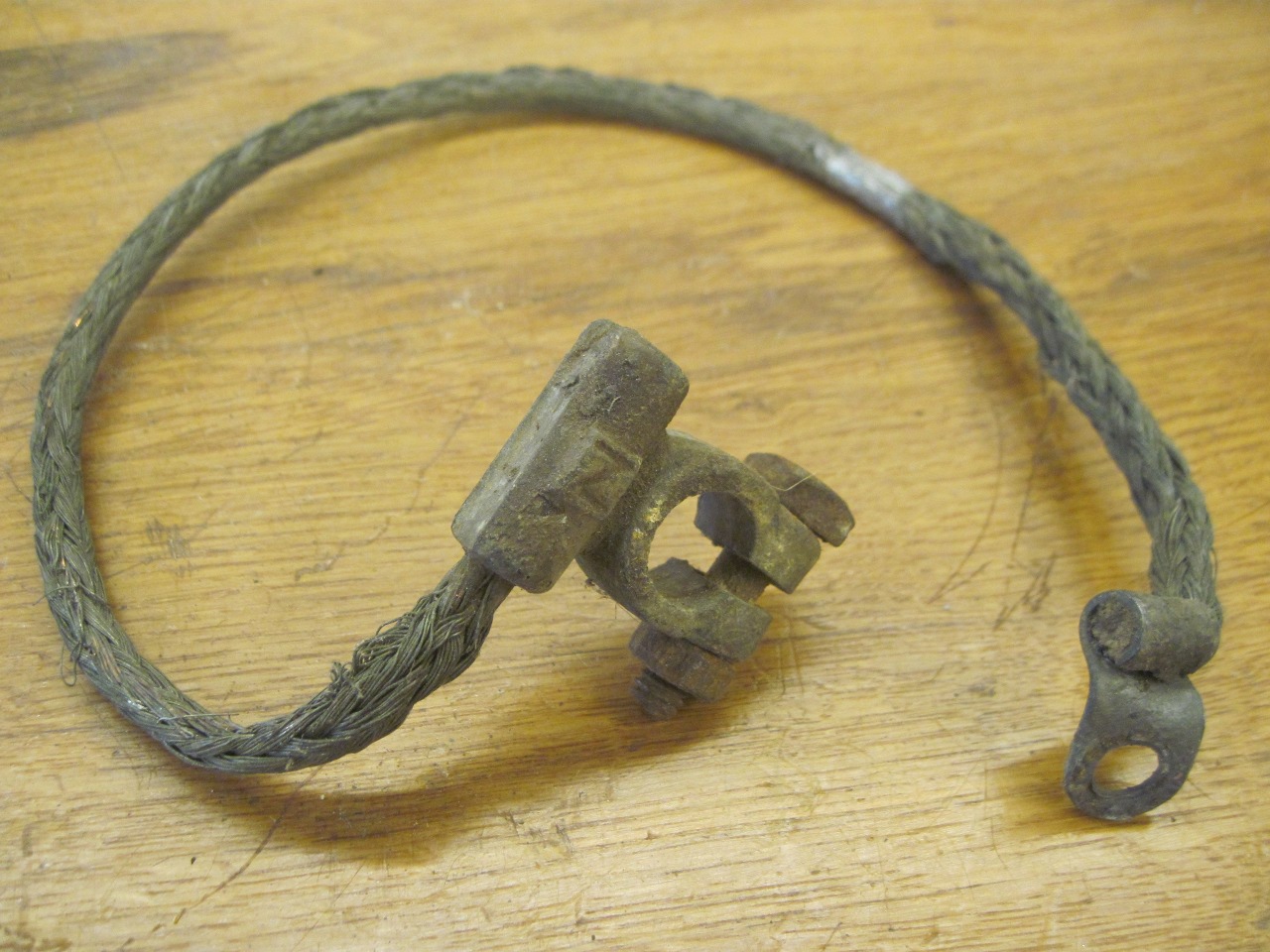
The ground
cable was heavy tinned copper braid that ran from the battery negative
terminal to a bolt on the rear plate of the engine. Crimped and
soldered along the way was a tap that was bolted to the firewall to
provide the return path the the body. The tap on my cable was
missing.
I
thought I could replace and maybe improve the battery cables by making
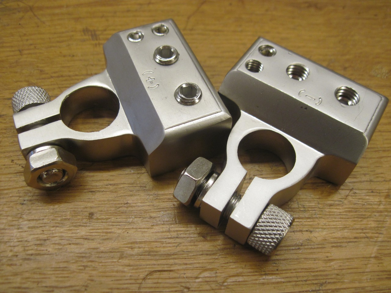
my own. I started by looking for battery terminal connectors.
I bought a set of these, based mainly on the glowing marketing
copy, plus the fact that liked the idea of all connections being
made directly to the connector, thus eliminating those taps on the
cables. The description of these items implied, or maybe I just
assumed, that they were made of tinned copper or brass. I was
disappointed to find that they are actually made of a coated pot metal.
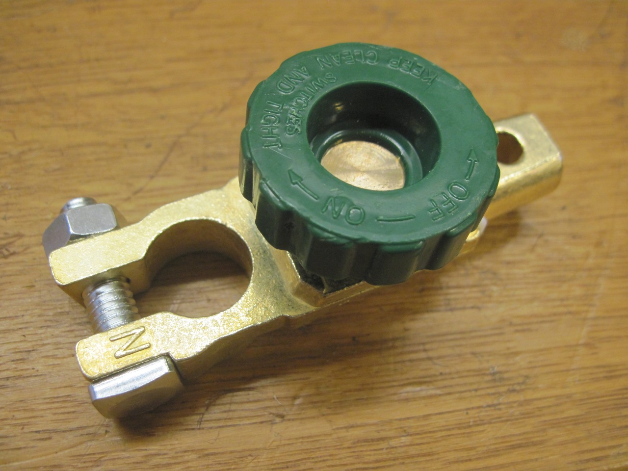
I
also wanted a main battery shutoff. I ordered one of these, and
was disappointed to find that under the nice but misleading brass color
was more pot metal.
Now
when I started this little project, I had no earthly intention of
making my own battery terminal connectors, but as I continued my
search, I really couldn't find exactly what I was looking for.
Then, while I was pawing through my scrap metal bin looking for
something else, I hit on this sizable chunk of copper and,
well, the deal was sealed.

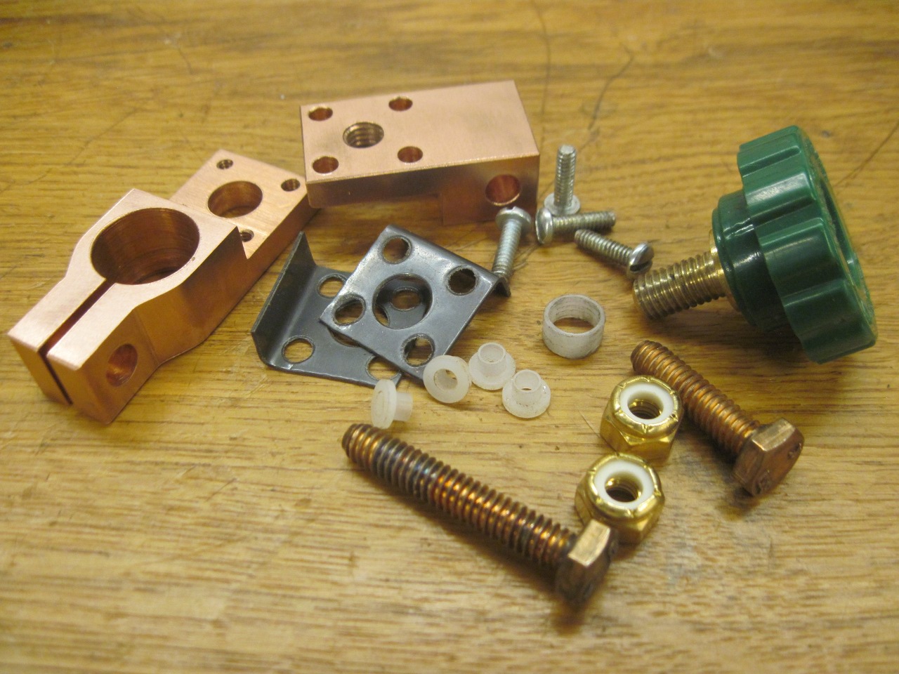
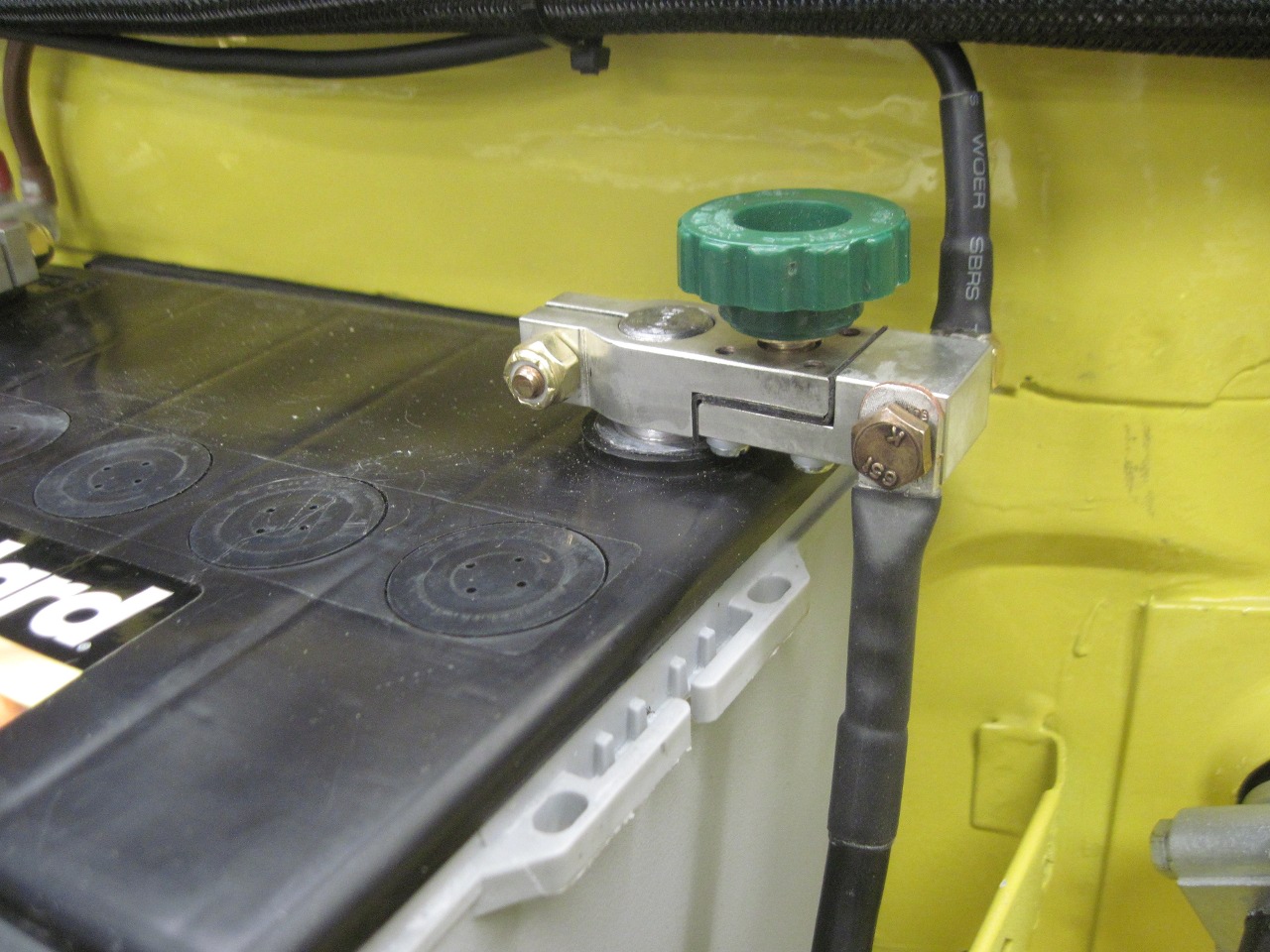
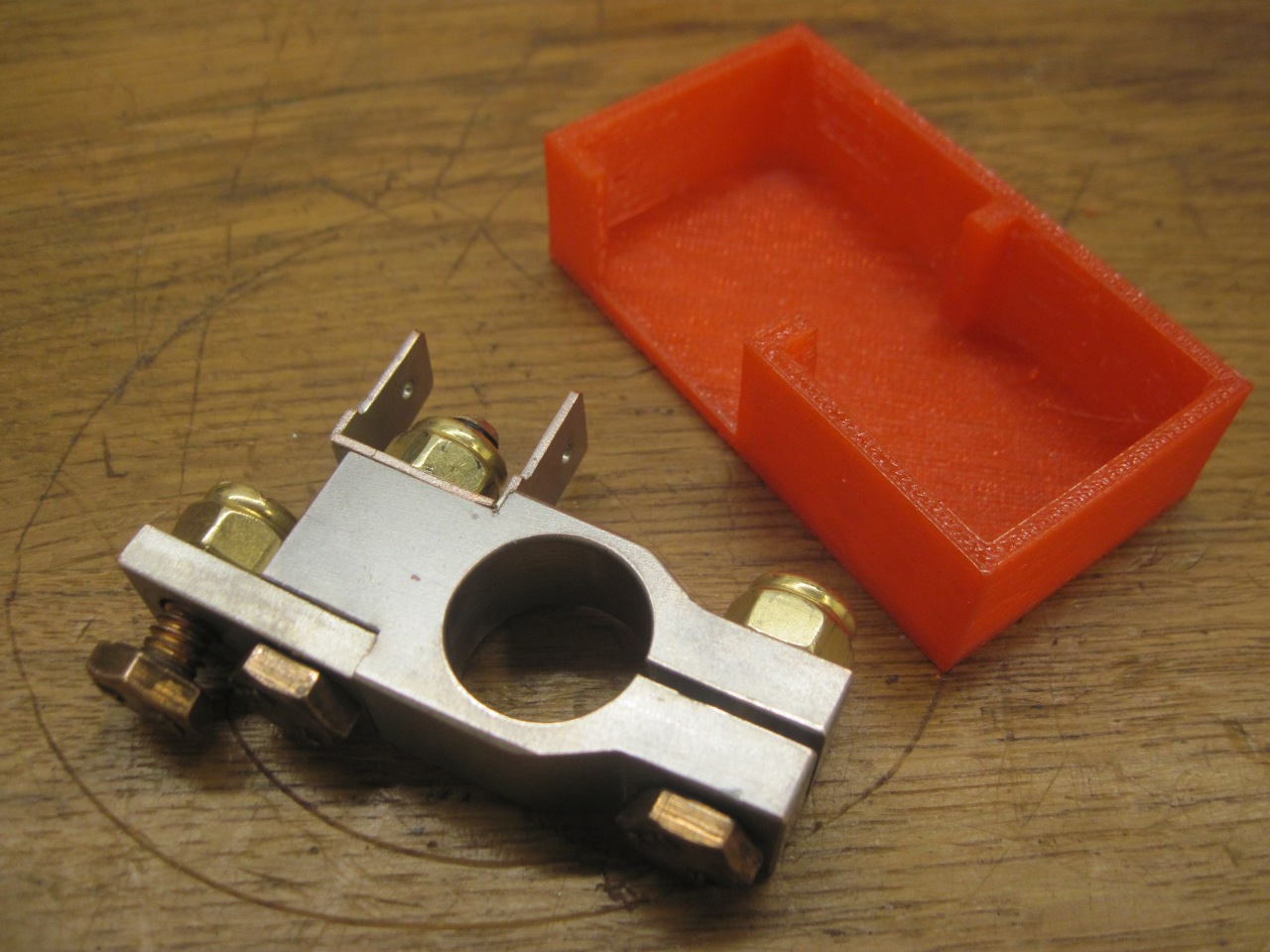
For
the negative terminal, I sort of copied the design of the
shutoff I bought, but with improvements. On the store-bought
piece, it is just the shutoff knob that holds the parts together.
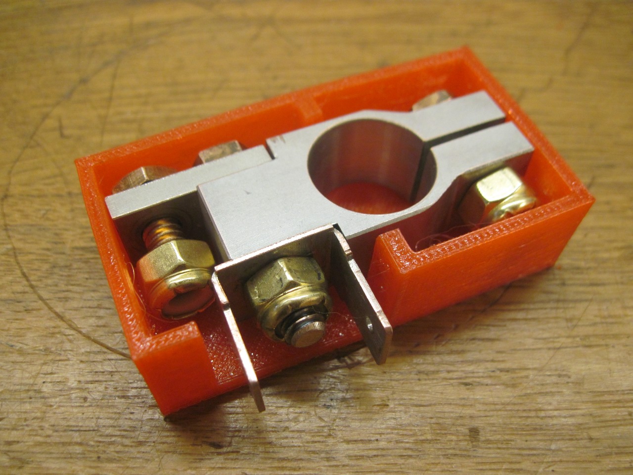
In my design, the two conducting parts are held together with
insulated screws, so the knob can be completely removed and the unit
stays solid. Also. the battery cable connects directly to the
piece with a terminal lug, instead of using another barttery clamp as
in the store-bought unit. I robbed the green knob from the
commercial unit to use in mine.

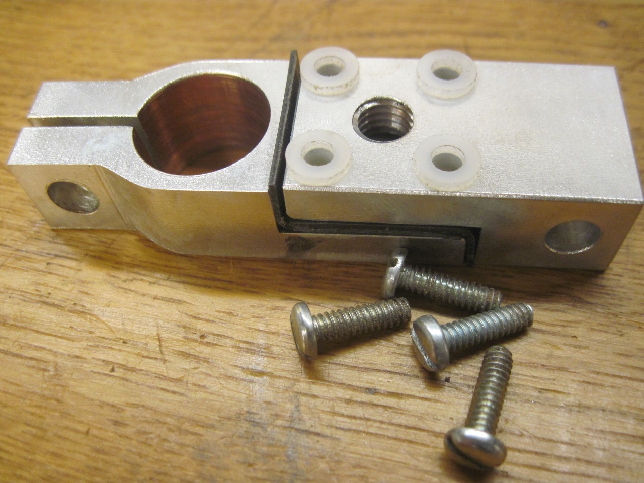
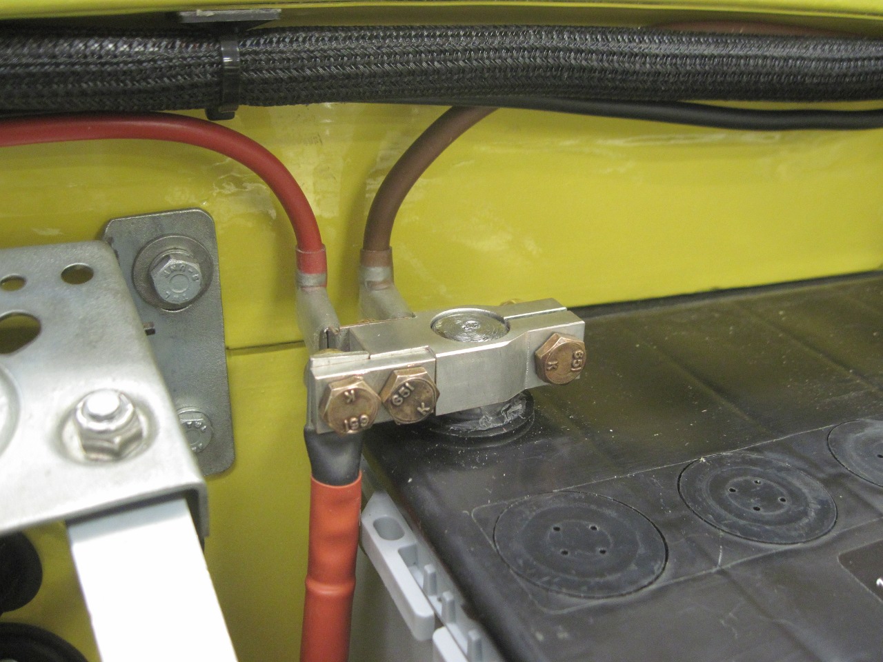
Foir
the positive terminal, I moved the connection points for the alternator
and system loads to the terminal body, instead of a tap on the cable.
The terminals look silver colored because they are coated with
tin to prevent copper oxidation.


OK, now for the battery itself.
The
battery for the TR6 was nowhere to be found, but I believe the stock
TR6 battery is a group size 24. To do some mock-ups, I stole
a battery out of one of the other cars, but it was smaller, so I jhad
to make up the difference with spacers. During these trials, I
decided that I'd really like the battery terminals to be at the rear of
the battery, sort of under the cowl. To me, it looked a little
more tidy that way, but it would require that the positive and negative
terminals be reversed. Group 24 batteries can be had with reverse
polarity, in which case they are designated Group 24F. The
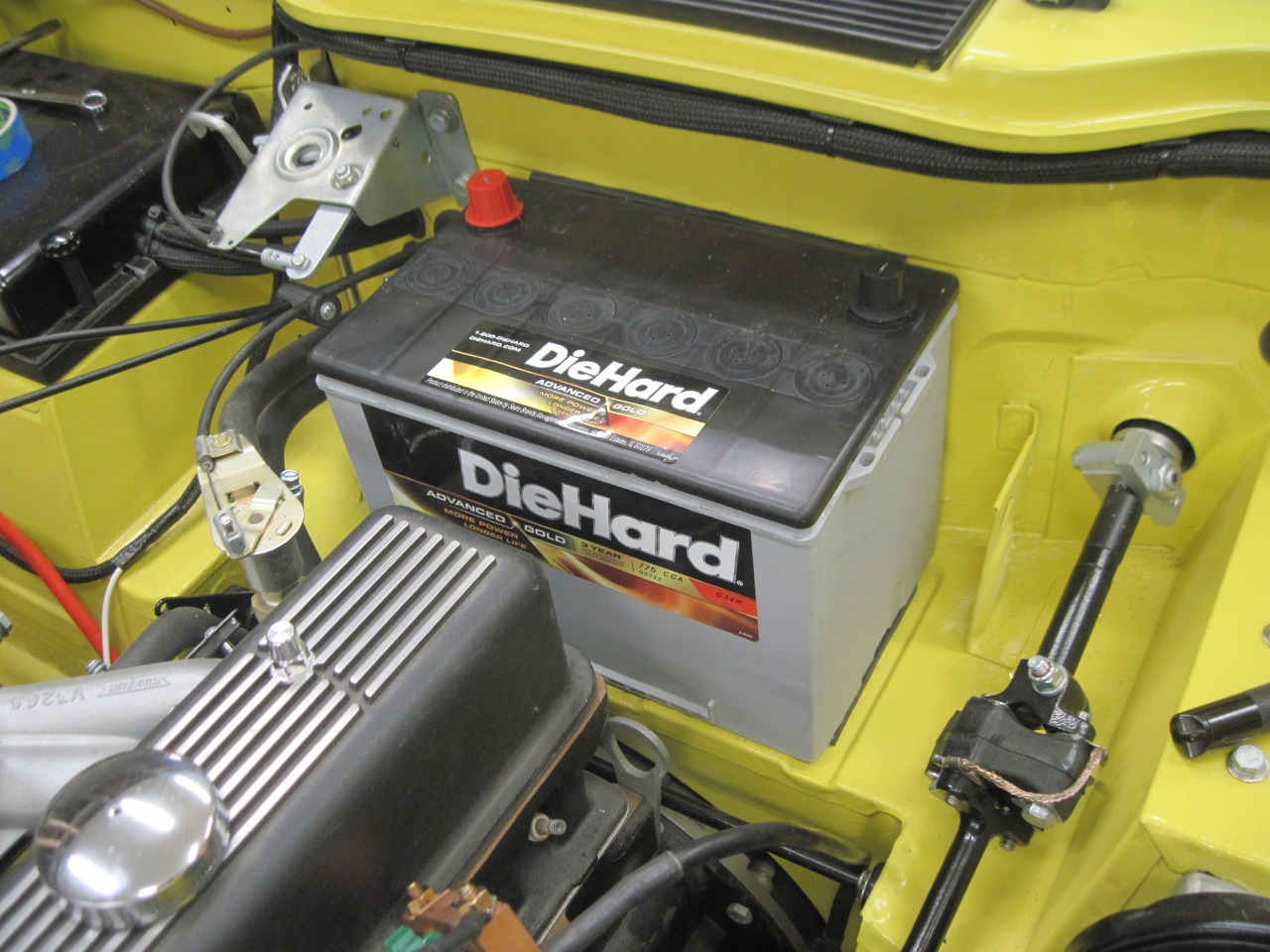
problem then became that the 24F battery is pretty tall, and the
clearance to the cowl was uncomfortably close. My solution was to
move to a Group 34 battery, which shares the footprint of the 24
battery, but is an inch shorter. Luckily, the 34 battery is also
available in a reversed polarity version called, inexplicably, Group
34R. After finally convincing the guy at Sears that I really did
want a 34R battery and not to worry about what car it was going into, I
got the battery.
This is an AGM (Absorbent Glass Mat) battery.
AGM batteries are more expensive than flooded cell lead acid
batteries, but are lower maintenance, and much less leak-prone.
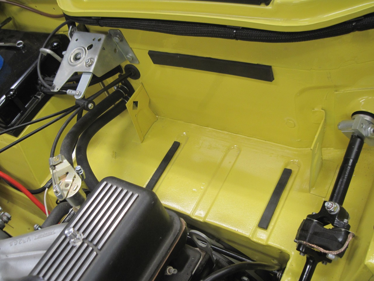
The rubber strips hold the battery off the paintwork.
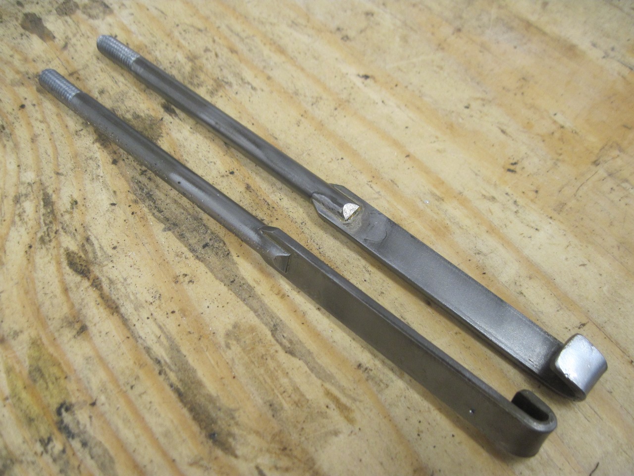
I
knew there must be some sort of battery hold down arrangement in one of
my boxes of assorted parts, and I finally found it. It looked
pretty acid-eaten, and even after I cleaned it up, it wasn't pretty.
The cross bar was severely pitted and the tension rod threads
looked to be just about stripped.
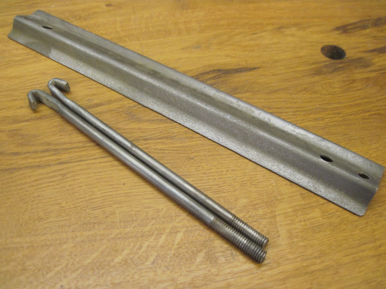
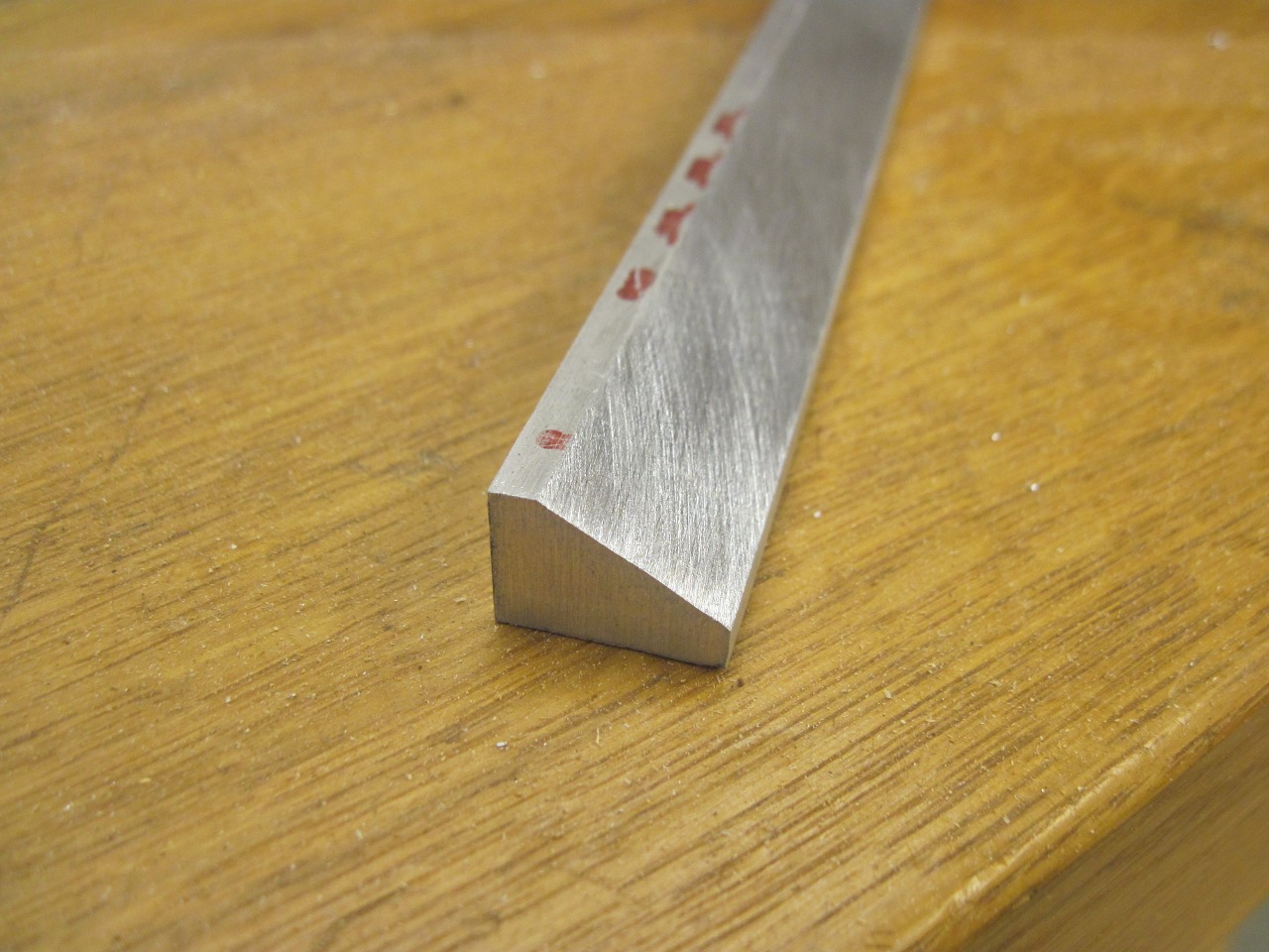
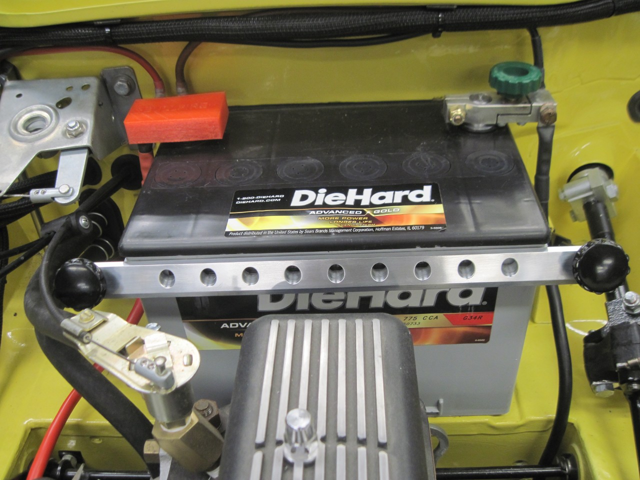
I made a new crossbar out of aluminum, but it looked sort of--I don't know--plain, I guess.
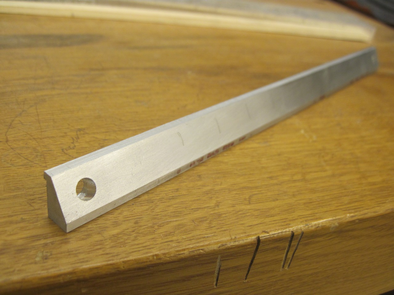
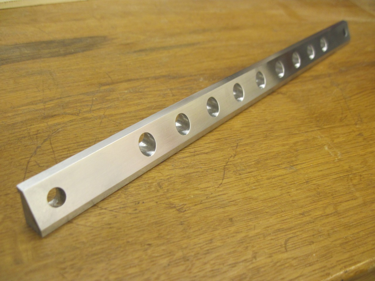
That's it! Some go-fast racing holes!
Some new tension rods and some nice plastic knobs.

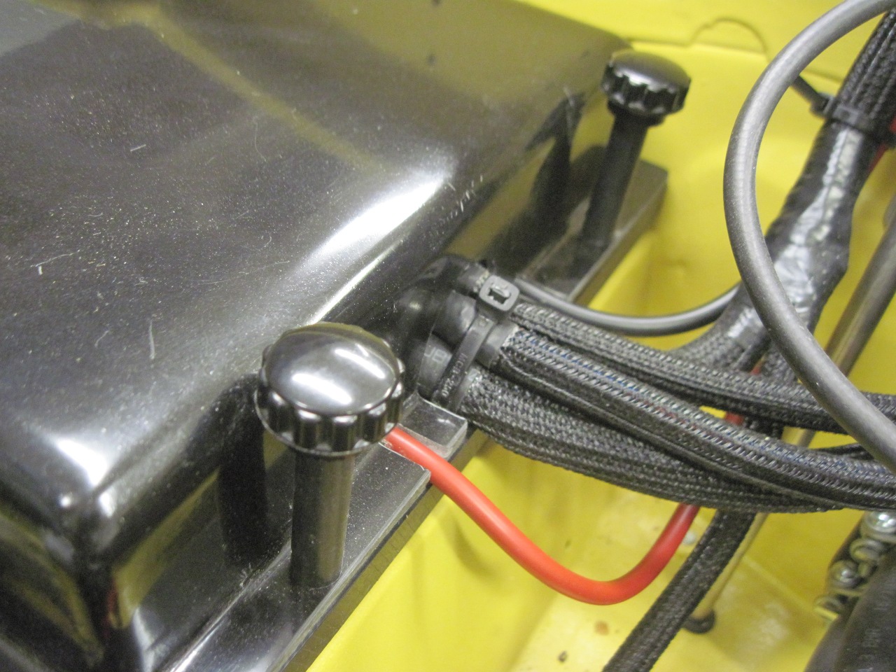
Finally
putting everything together. On the positive terminal, the
smaller red wire is 8 gauge to the Power Module. The brown one is
120 strand (approximately 8 gauge) to the alternator. The large
red is 4 gauge to the starter. On the negative, black 8 gauge to
the Power Module, and black 4 gauge to rear engine plate. No need
for a connection to the body since it is no longer used for any ground
returns.
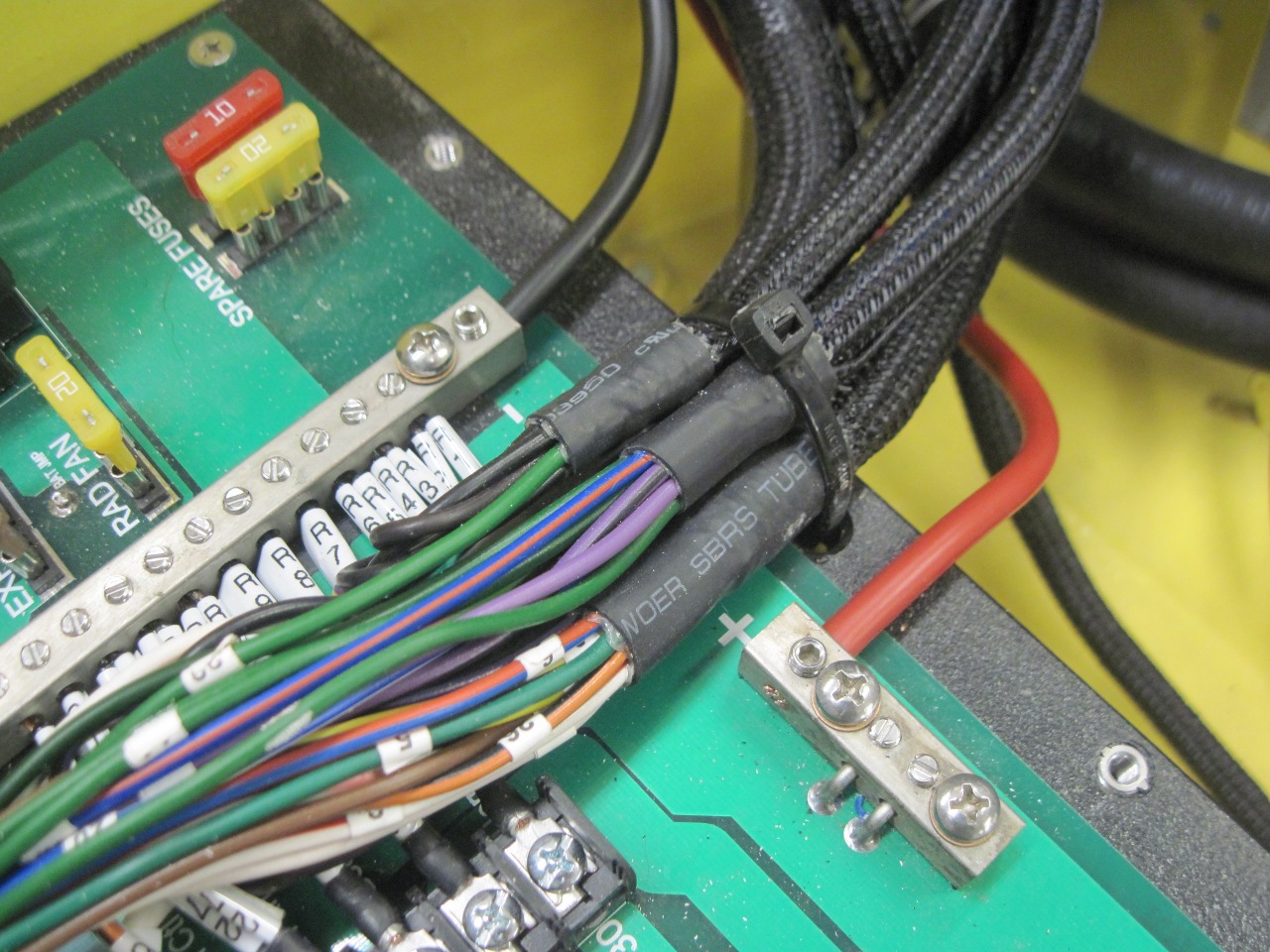
The Power Module get its input power connections.
The last touch. I love this 3D printer!
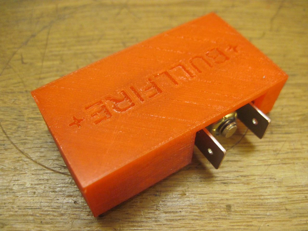
All done.
Before
I closed the shutoff switch, I thought it prudent to put an ammeter
across the switch to see if there would be any current flow. It
read a couple of hundred milliamps. I didn't understand.
Everything on the dash was switched off. I studied the
wiring diagram. Where could this current be going? Long
story short, my doors are not installed, and the door switches were
closed. The interior lights weren't bright enough to se in the
daylight. That was good for over an hour. Glad I didn't
start taking things apart.
This was a fun one. Even the
obsessive part with the battery terminal connectors was enjoyable.
In principal, with a little more plumbing, I could try to start
her up. I'll probably wait until Spring, though.
Comments to Ed at: elhollin1@yahoo.com
To my other TR6 pages