To other pages
December 15
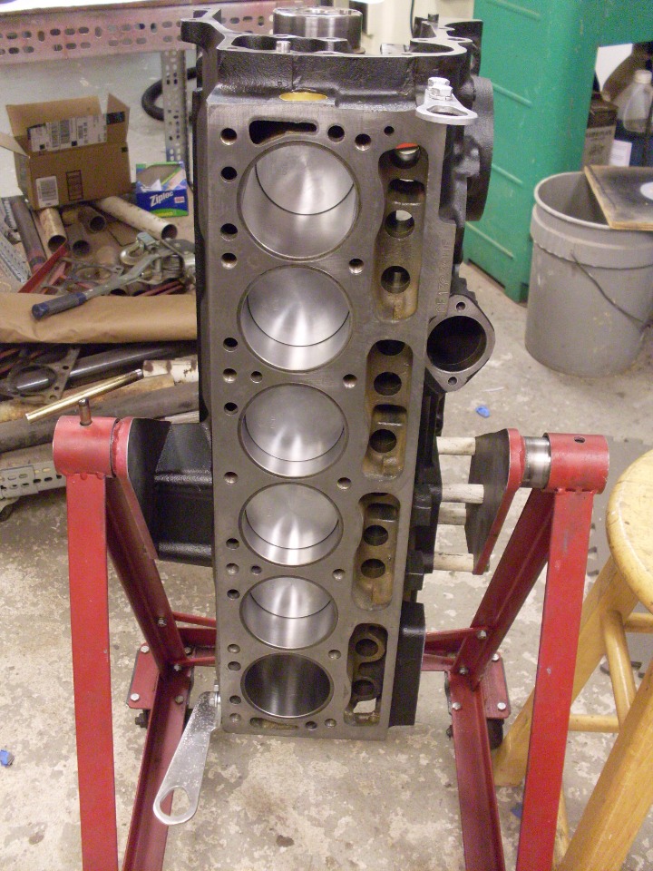
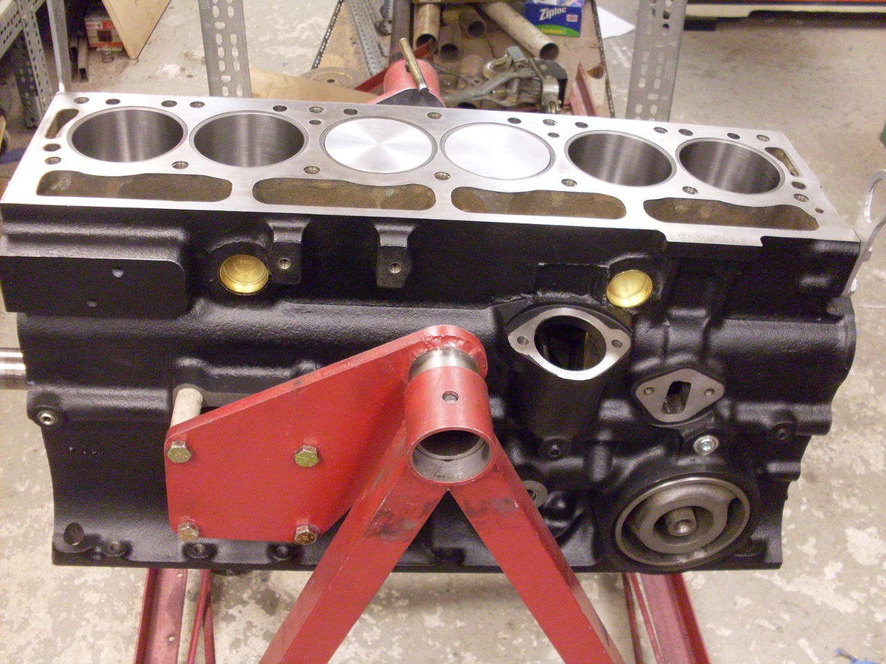
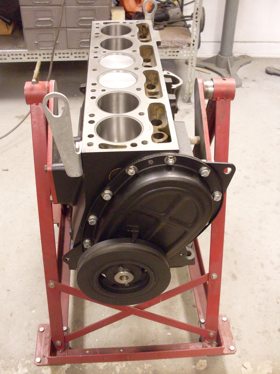
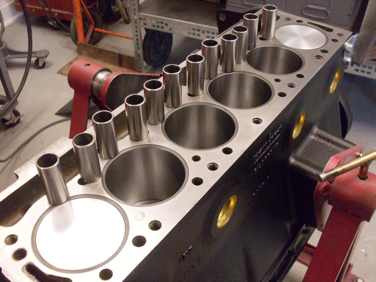
Block Assembly
[click the pics for a larger view]
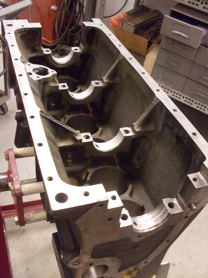
I
got the block back from the machine shop, and am getting it ready to
install the crank and pistons. First, I wanted to give it a coat
of paint. I masked the machined surfaces and shot it
with Duplicolor high temp engine primer and paint:
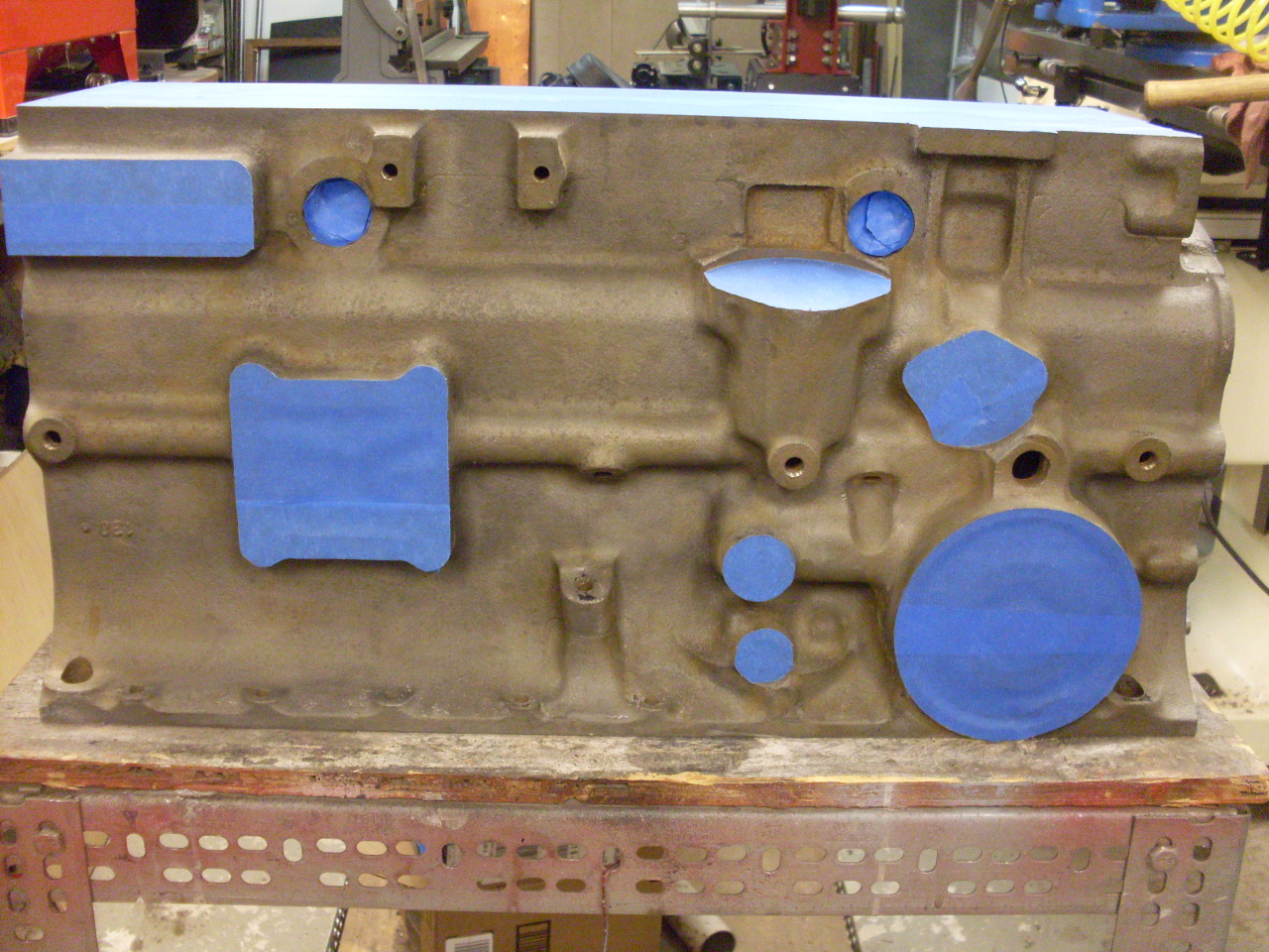
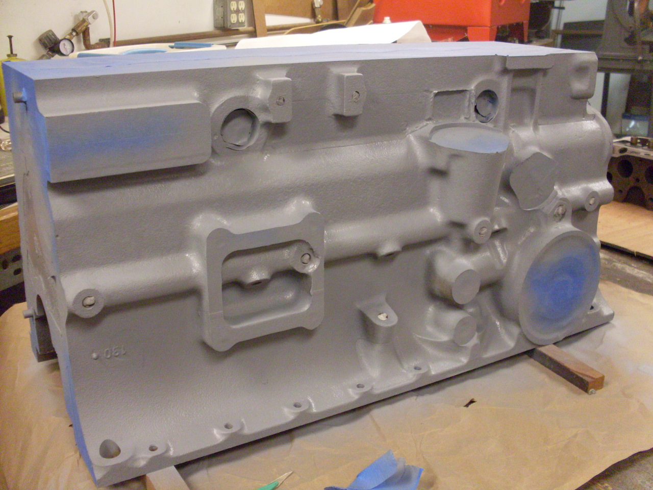

I realized after this that not all of the machines surfaces should have been masked, but I'll take care of that later.
After
the paint was cured, I spent some time with various sizes of taps,
chasing the threads in all of the bazillion or so threaded holes in the block.
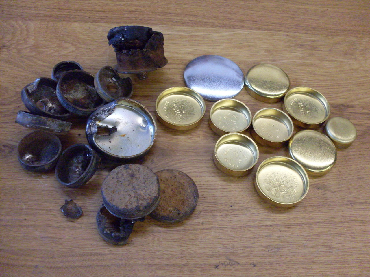
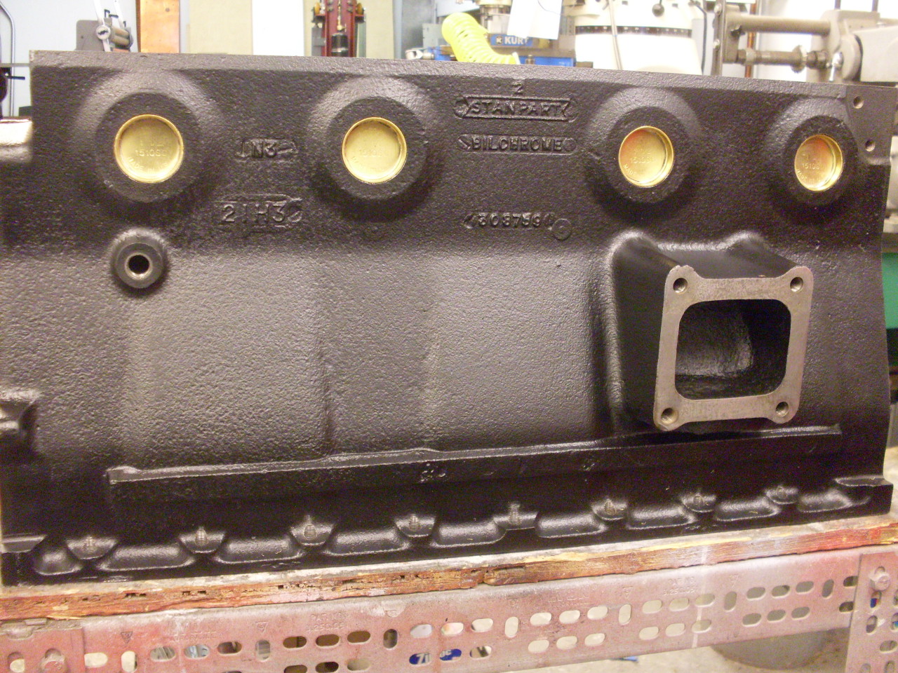
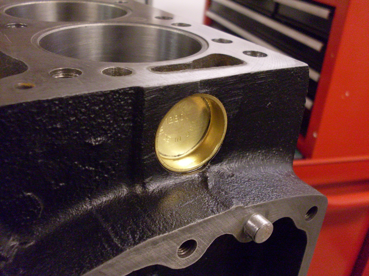
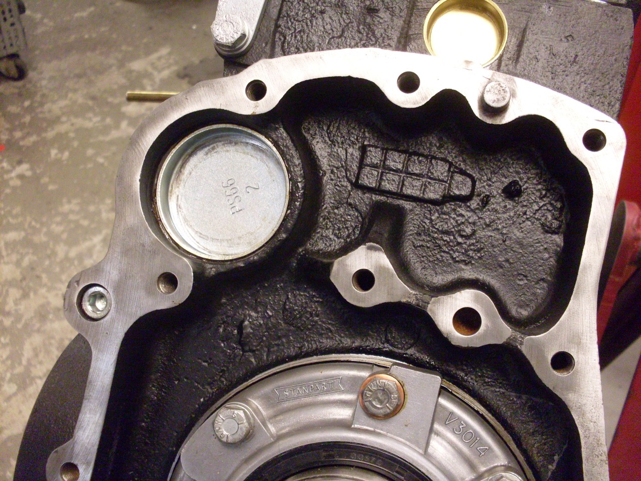
Next
up were the core plugs. I opted for brass ones, partly in the
hope that they will corrode slower than the steel ones, and partly
because I like the looks. On the previously leaking core hole, after
I cleaned it up and measured it, I decided that it could still be used
as is if I added some sealer to the joint as insurance, which I
probably would have done anyway. One of my favorite sealers is
Permatex #3D, and I used it to seal the core plugs and the oil gallery
plugs. Core plugs were driven home with appropriate sized sockets as drifts and a dead blow hammer.
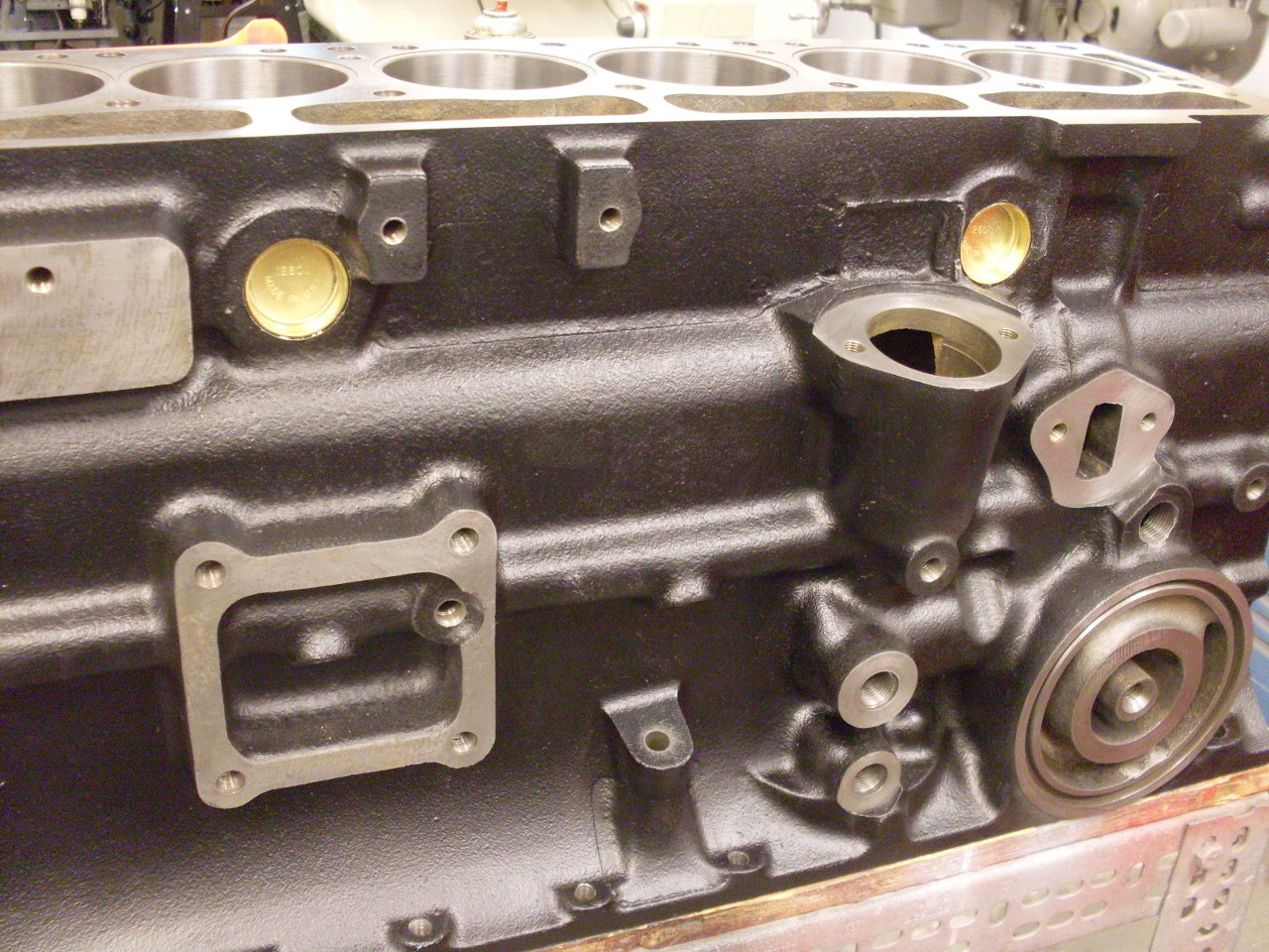
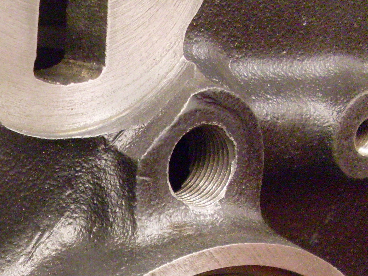
Then,
the oil gallery plugs. I carefully cleaned all the oil passages
with small wire brushes, then blew them out with compressed air.
There are seven 1/8" pipe plugs on the left side of the block
along the main oil gallery. Three of them cover drillings that go
up to the intermediate cam bearings, and the other four cover drillings
that dog-leg down to the crank main bearings. The rear end of the
main oil gallery gets a 1/4" plug. The front end of the main
gallery had the soft metal plug that was drilled out. The hole
was already tapped for a 1/4" pipe plug, but not deep enough. The
plug has to end up at or below the surface of the block so it doesn't
interfere with the front plate. (There is a hole in the front
plate that looks like it was intended to accommodate the plug, but it
doesn't line up. The gasket agrees with the plate. Not sure
what the story is there.) A 1/4" pipe tap took care of the
problem. I was careful to blow out all the chips from that
operation.

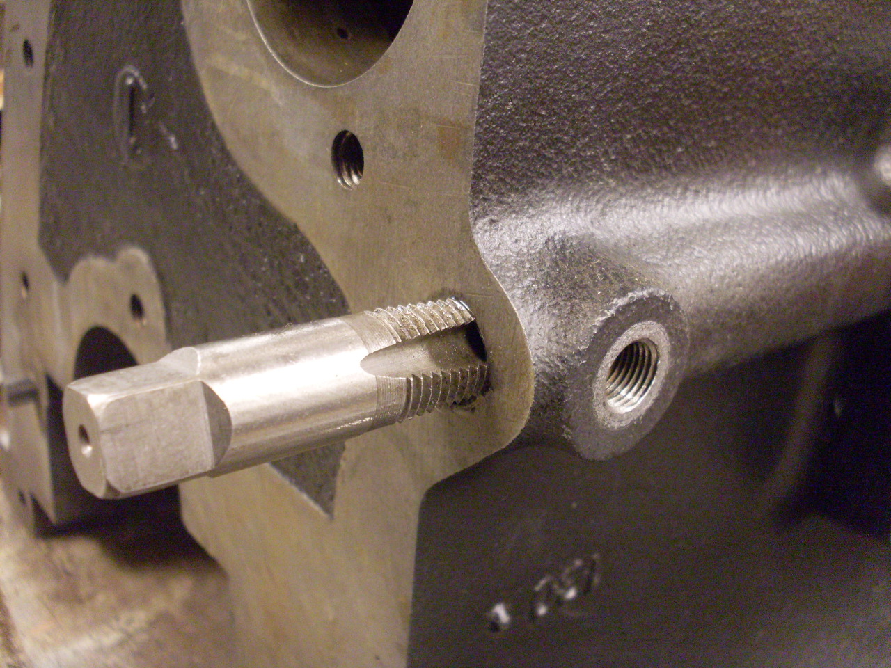
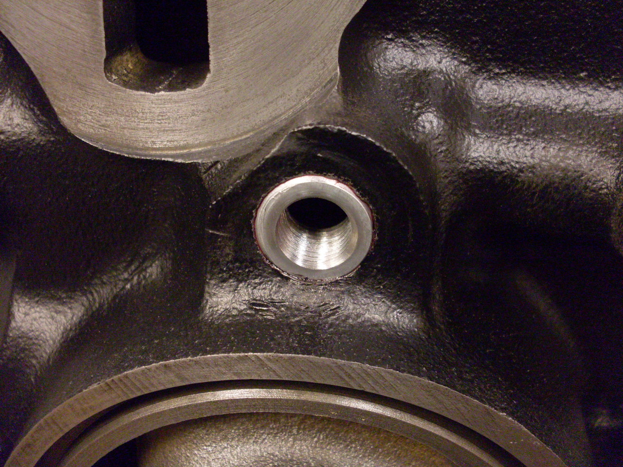
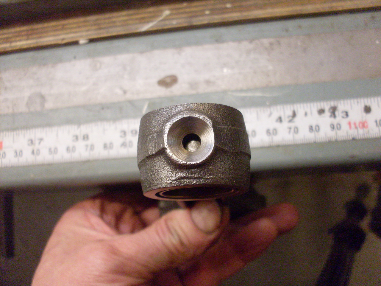
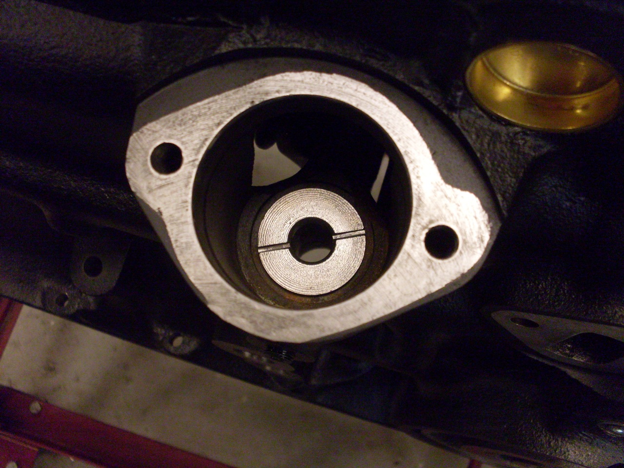
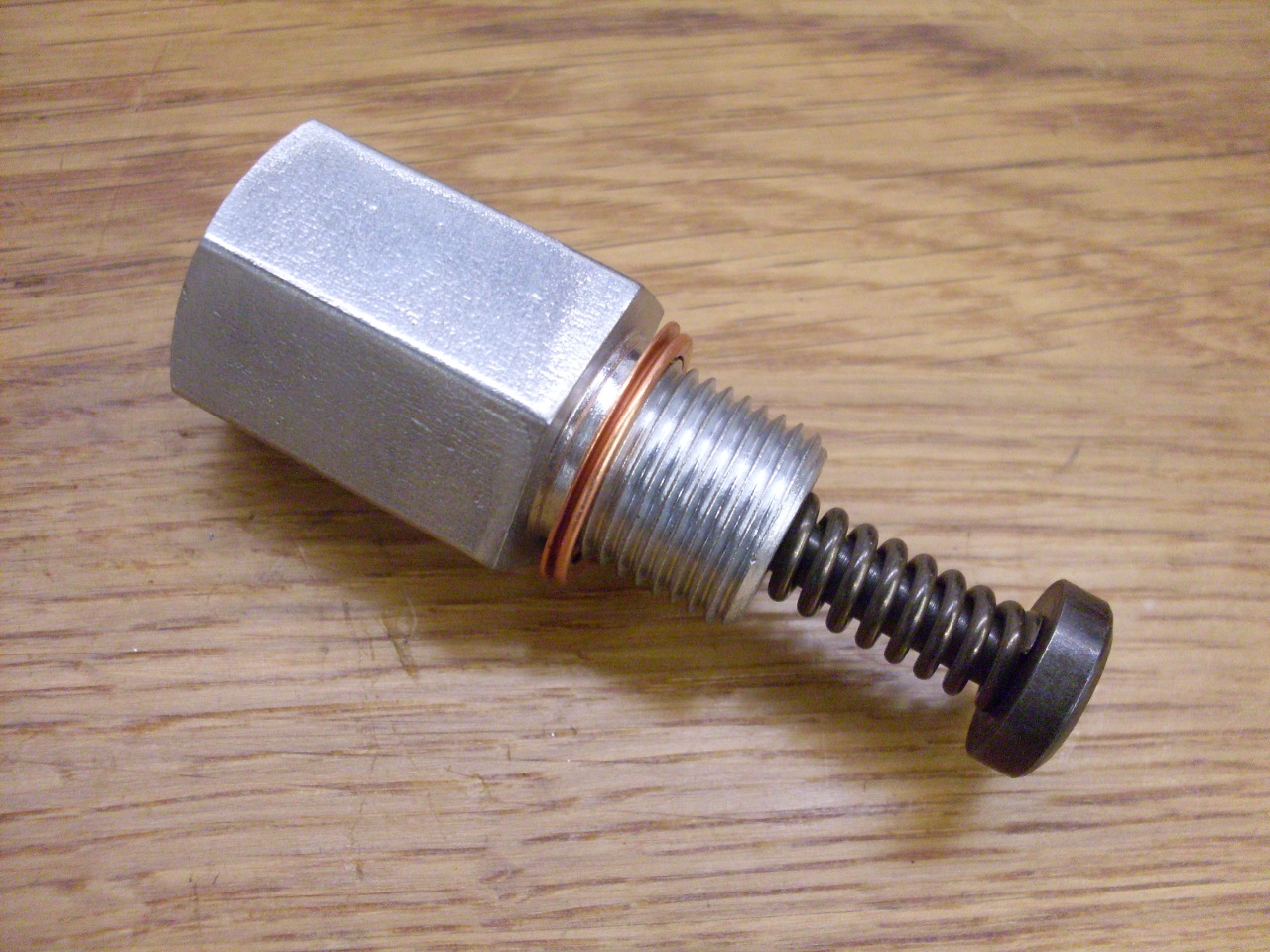
Then
there was the other hole that had the drilled out soft plug. This
one was threaded 3/4-16, which is not a pipe thread. It is a
straight thread normally seen in hydraulic fittings or on drain plugs.
In either of these applications, a seal would be accomplished
with some kind of sealing ring against a machined surface. Since
there wasn't a sealing surface around this hole, an off the shelf plug
wouldn't work.
I
solved the problem by making an adaptor from a 3/4-16 bolt. I cut
it off short and drilled and tapped it to accept a 1/4" pipe plug.

I
installed the adaptor in the block with red (permanent) Loctite.
This will help some future rebuilder by preserving the removable
plug.
Installed new plugs along and at each end of the oil gallery.

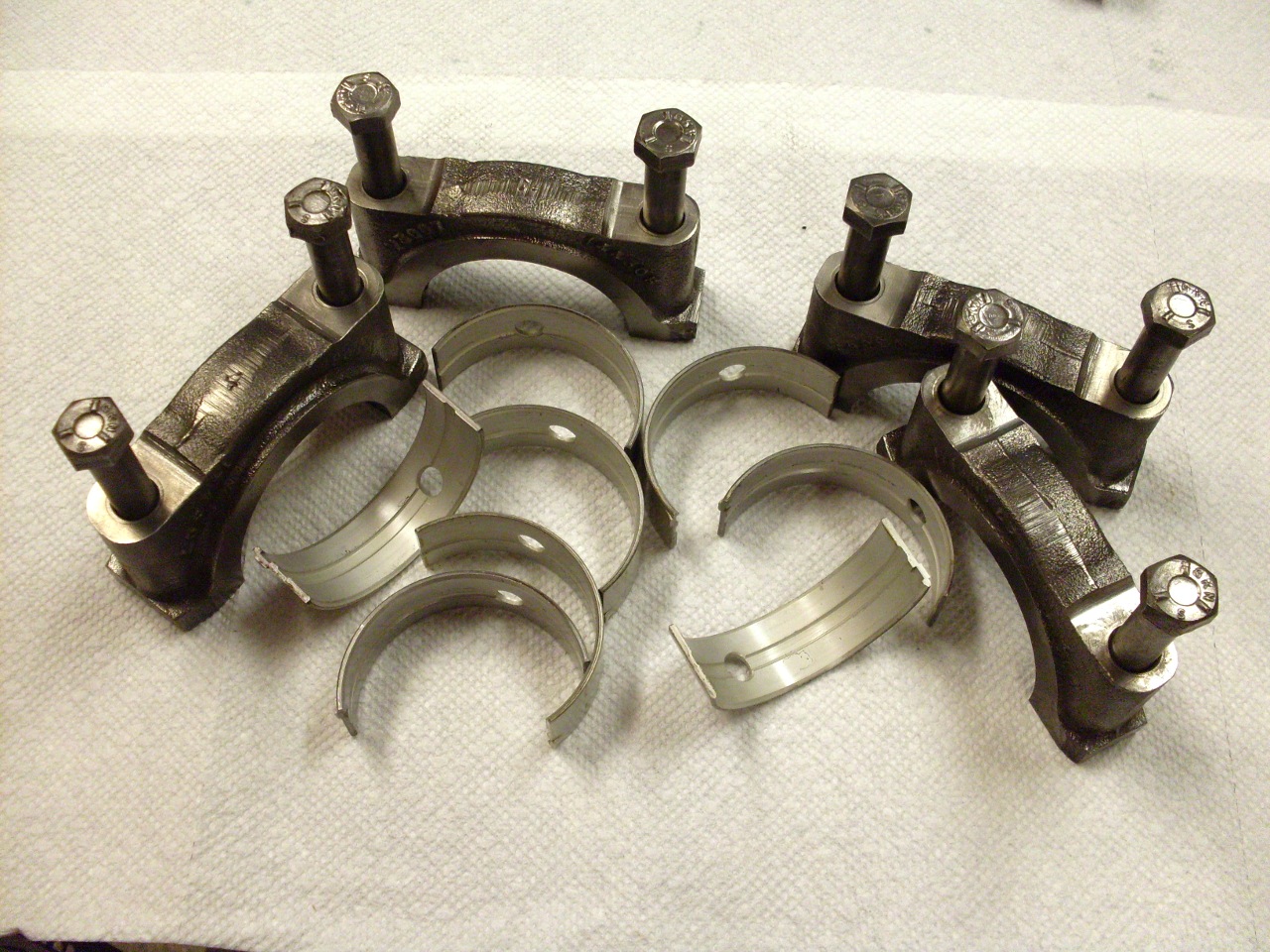
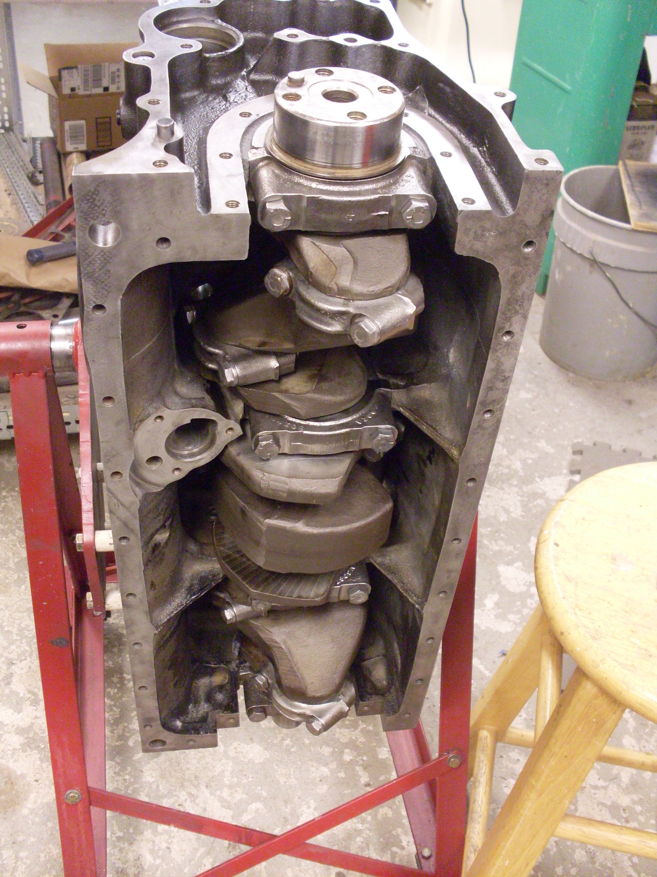
Cleaned
up the main bearing caps, unboxed the new tri-metal -0.010 main
bearings, and snapped half of them into the block. Applied a
generous amount of assembly lube, and gently lowered the freshly
reground crank in place.

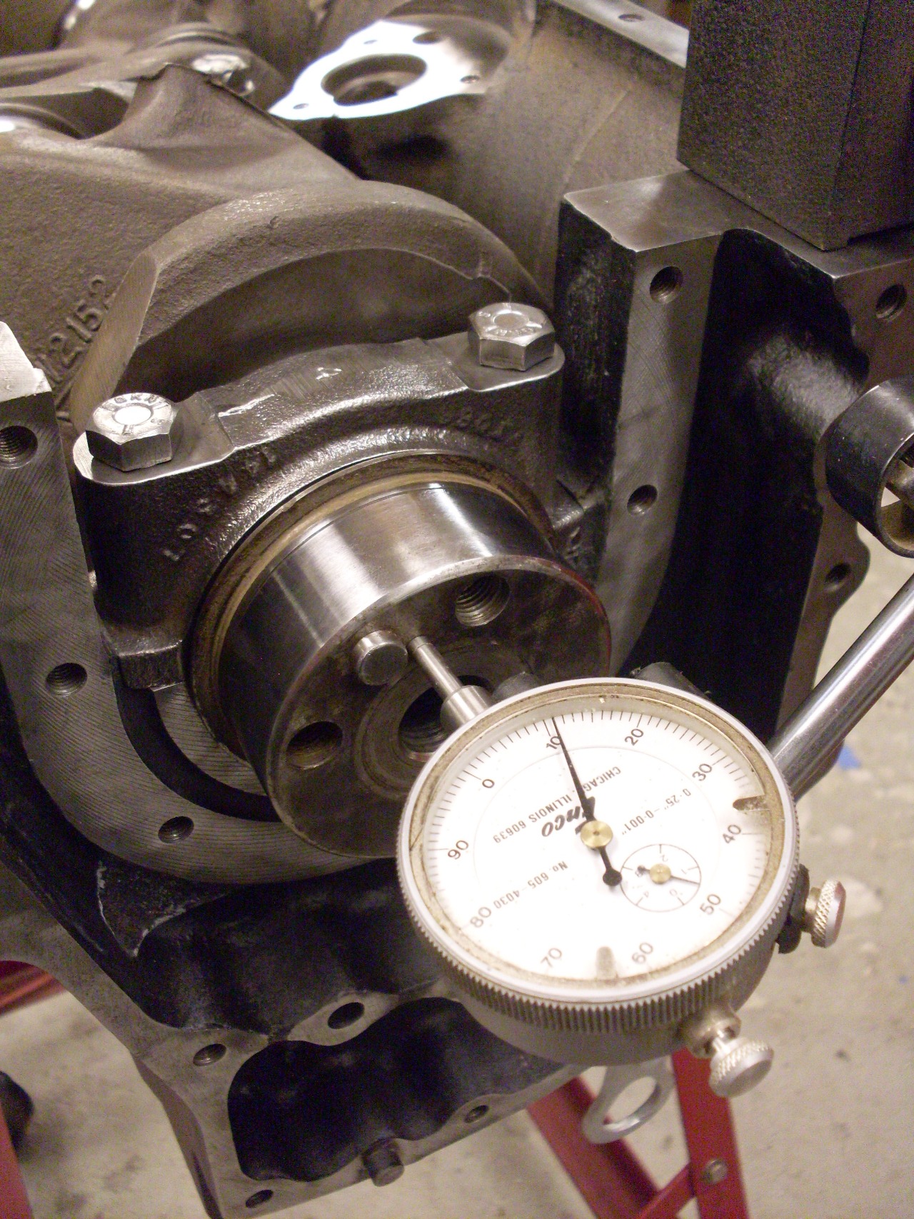
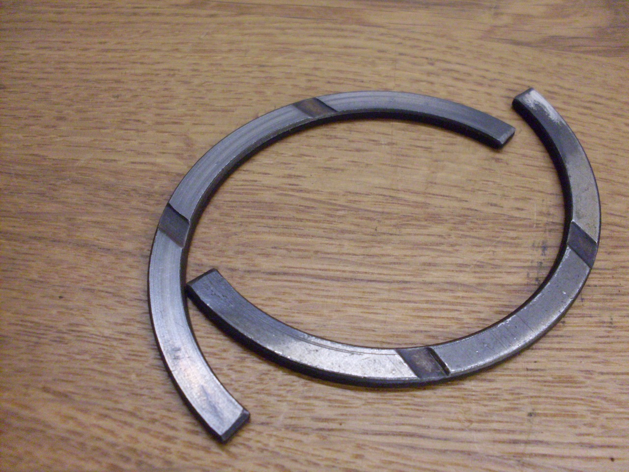
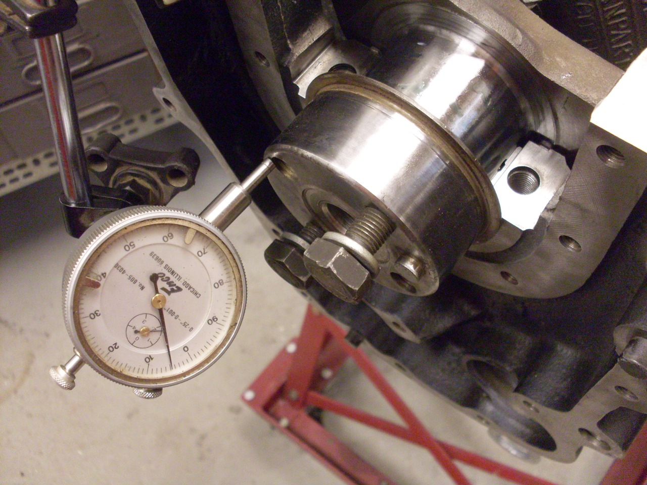
Before installing
the main bearing caps, I slid in the old thrust washers so I could get
an end float reading. It repeatably read 0.011"--out of spec, but
it could have been worse. The thrust washers actually look to be
in pretty good shape and measure 0.090 and 0.092, but I'll order a
standard and a +0.005 set and find a combination that brings me back
into spec.
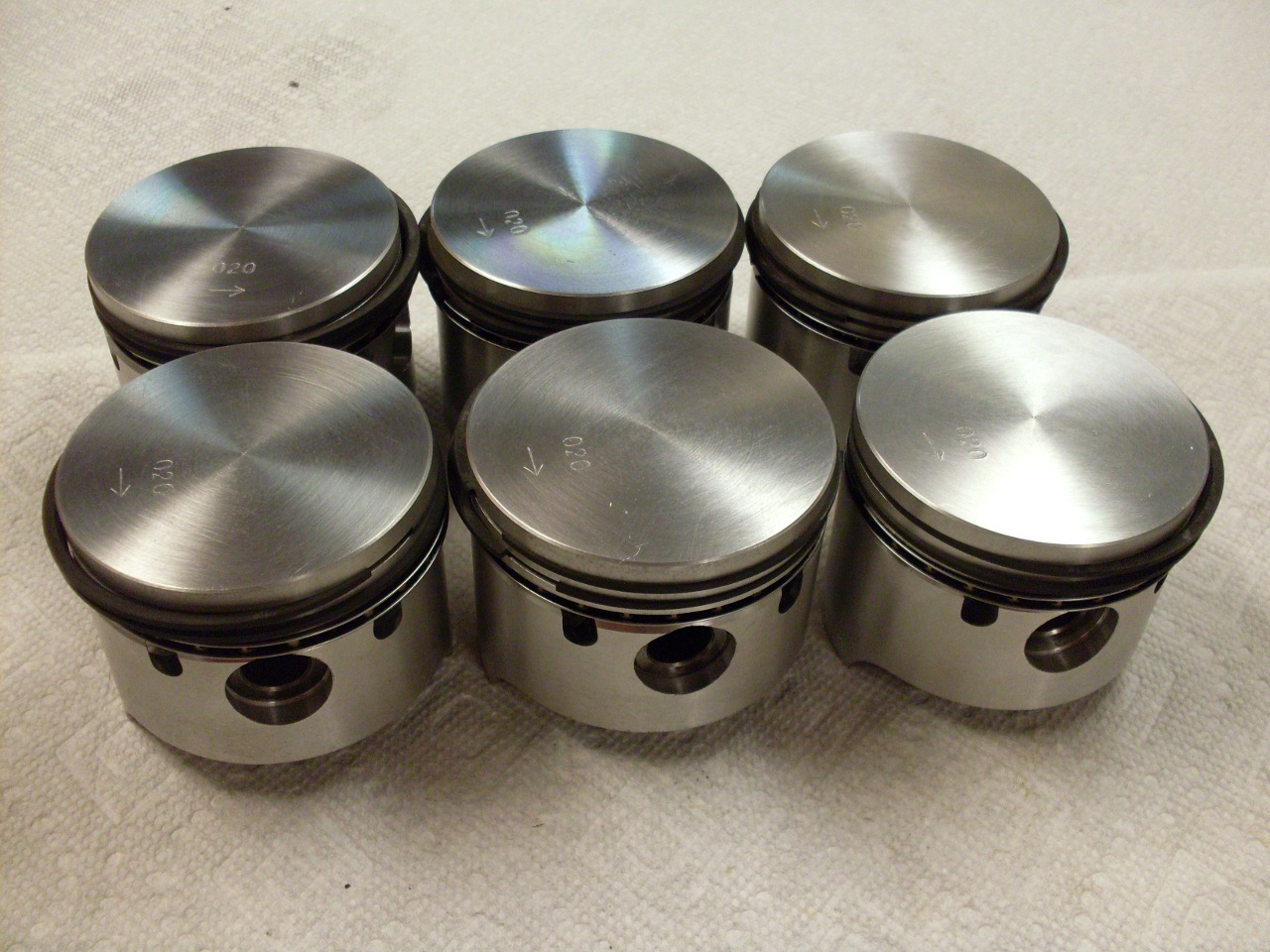
Installed the rings on the pistons. The last one went a lot faster than the first one.
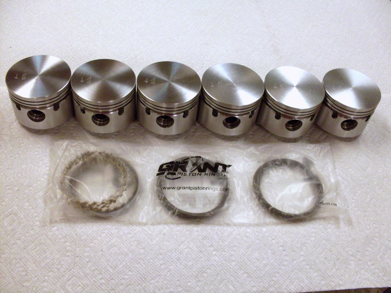
As
I was checking the small end bushings for size, I noticed that one of
them had shifted a little but so that the lubrication hole in the top
of the rod was apparently blocked.

I
wondered how this bush (which still measured well within spec by the
way) managed to survive. Finally, there are two answers to this.
First, though the oil hole appears to be totally blocked, if the
little conical well at the top of the rod is filled with WD40, it will
slowly leak out, and appear inside the bush, showing that there was
still a path for lubrication, even though it wasn't visible.
Second, these are full-floating wrist pins, which means that they
are not designed to be held rigidly by either the rod or the piston.
Even with no lube on the small end bush, the pin is free to turn
in the piston, and probably does on some pistons. In
fact, the specs for wrist pin and small end bushes allow for a mild
interference fit between the two. The fact that my small end bushes
were still in spec, and in fact didn't show any signs of wear suggests
that most of the relative motion was between the pin and the piston.
After
pushing the errant bush out and reinstalling it, I did a
rudimentary bend and twist check on a surface plate, and then assembled
the pistons to the rods.

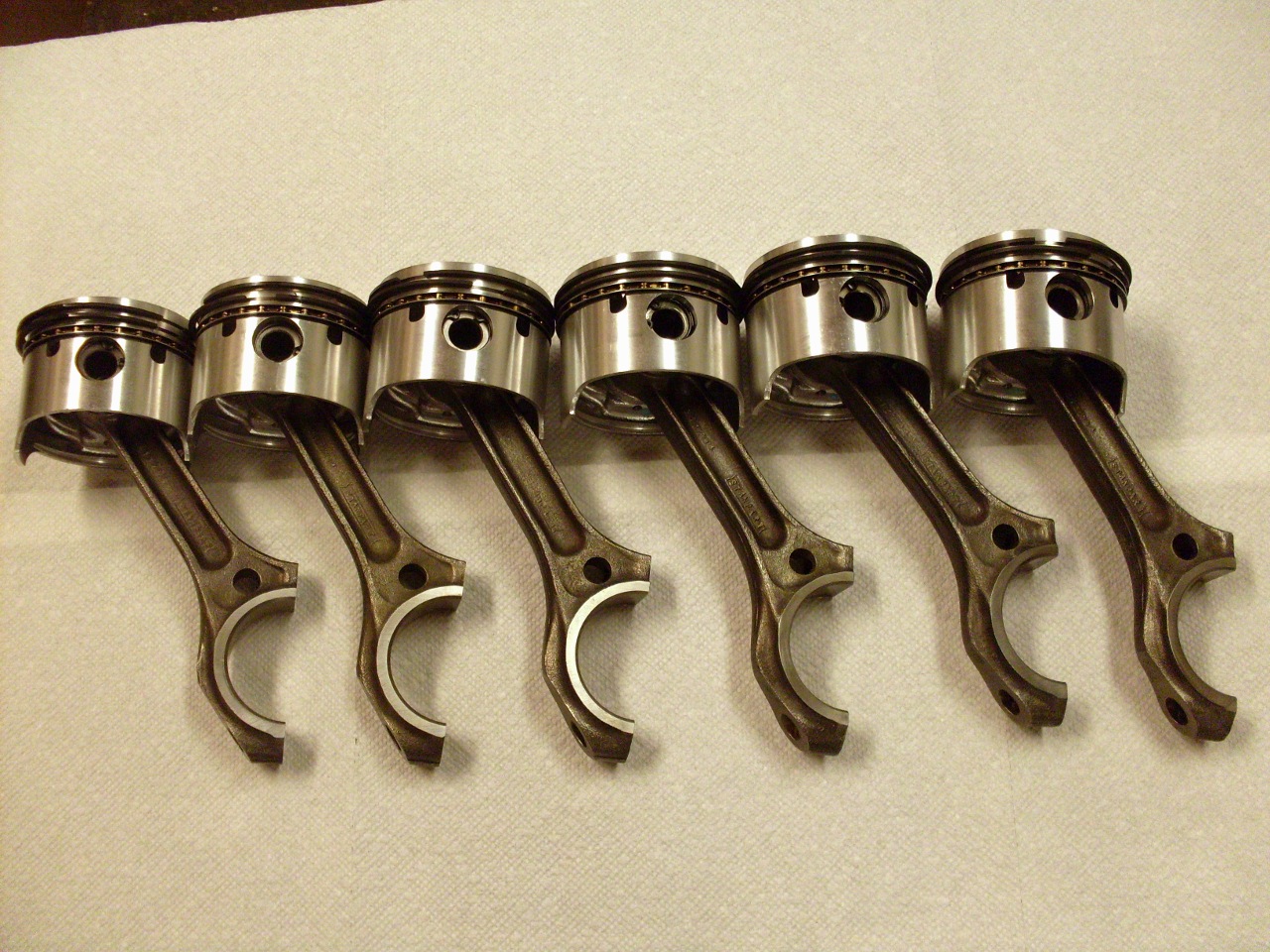
Installed
the pistons, being careful to put the rods on the same crank pin they
came off of. After each piston, I turned the crank to make sure
nothing was bound up. It got progressively tighter and tighter,
but with all six pistons in place, the crank still turns (with some
effort).
Update
January 14th, 2014
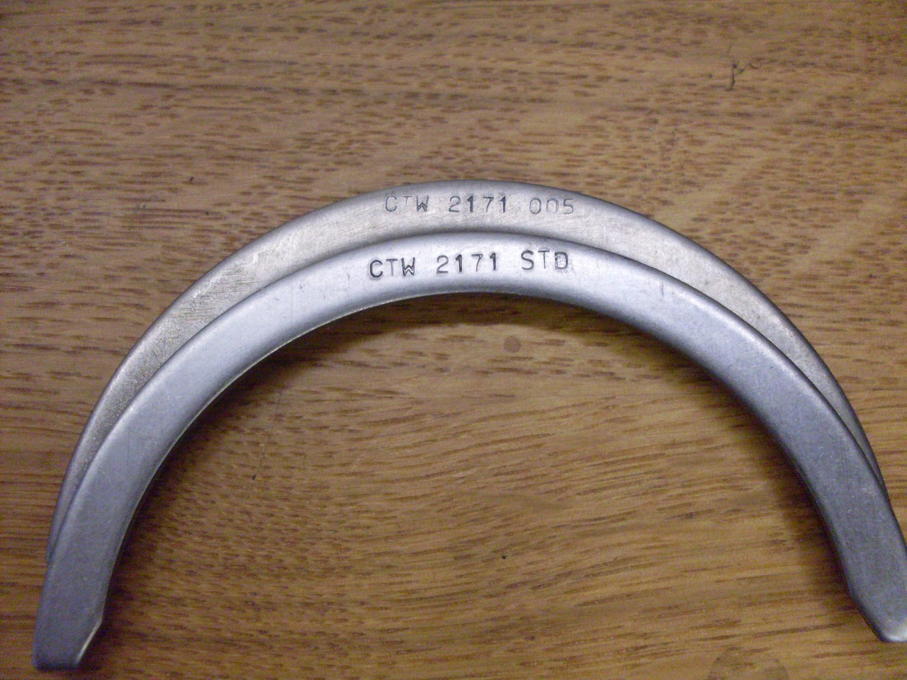
I
got the thrust bearings, and installed one standard and one +0.005"
item. This brought the end clearance down to just under 0.005".
There are folks who opine that the TR6 thrust bearings are such a
weak link in this engine that they should be upgraded to a bigger,
stronger, shinier part. There are other folks who are willing to
provide parts that fit that description. I sometimes wonder which
group came first. This car has 65K+ on the odometer, but probably
closer to 85K on the engine considering alll the speedometer troubles I
had. The 0.011" end float I had was certainly out of spec for a
new engine or rebuild, but still a long way from any real danger of
catastrophic failure or permanent damage. The thrust bearings
were in no worse shape than my rod bearings. Maybe it's the way I
drive, but I'm not really seeing the weak link theory.
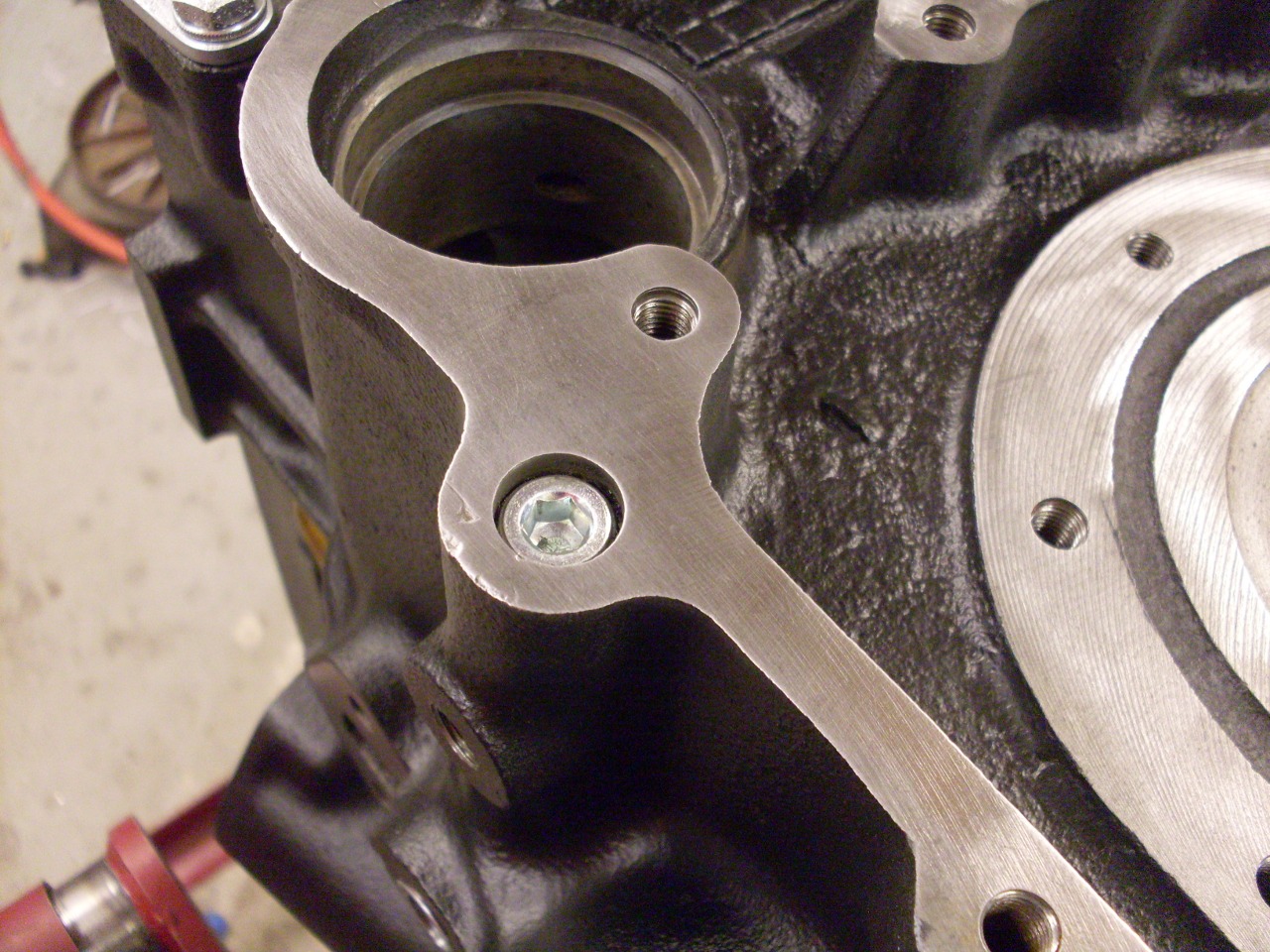
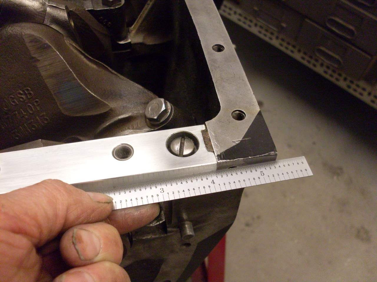
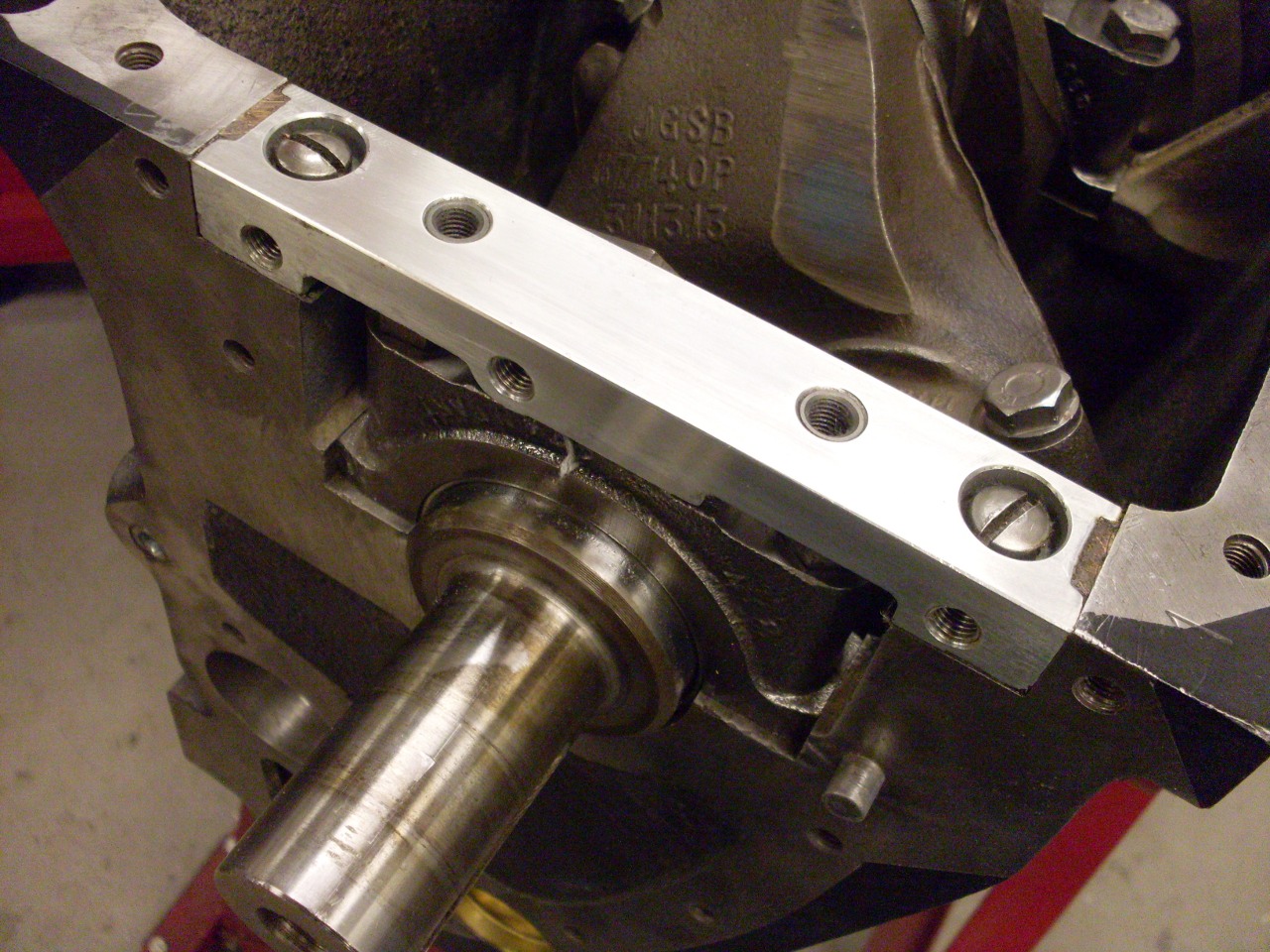
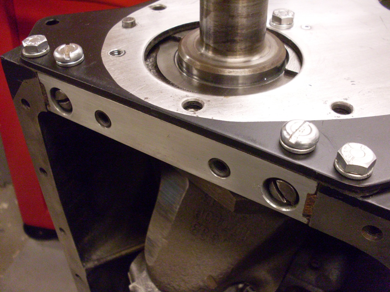
Next
up was the front sealing block. It is the part that bridges over
the front main bearing and forms part of the oil pan and front plate
sealing surfaces. I fixed up the stock block with some thread
inserts (see details here).
Using home-made gaskets (because they fit better thant the store
bought ones), and home made wood end seals (ditto), I lightly snugged
the block down, and adjusted it to be flush with the engine block at
the front, then torqued it to spec.
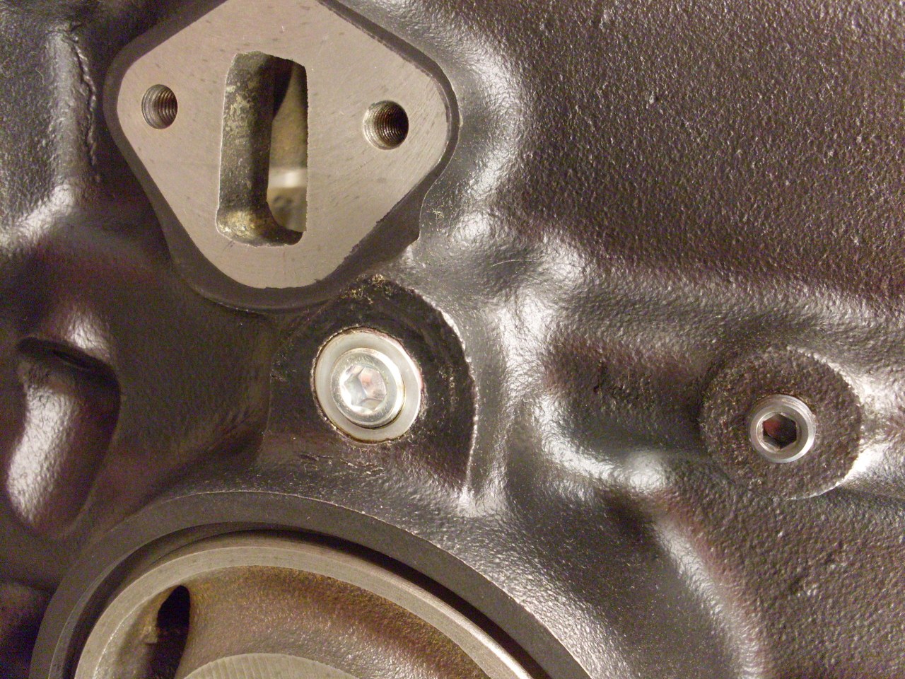
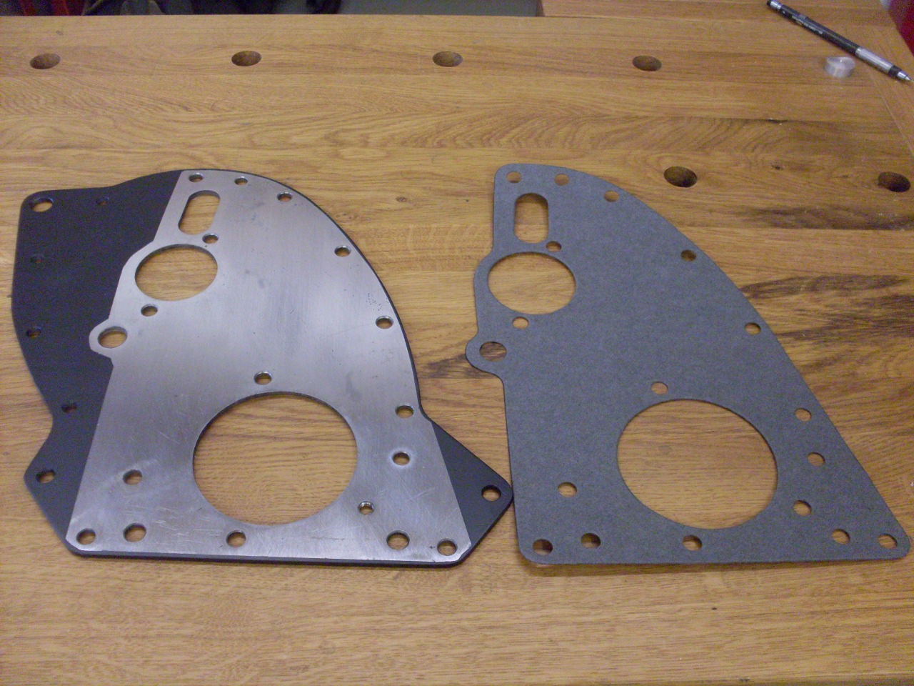
Then
came the front plate. I like to pre-prime and paint all the
surfaces that will be exopsed to the elements. I run the paint
slightly under the gasket so there isn't a bare gap.
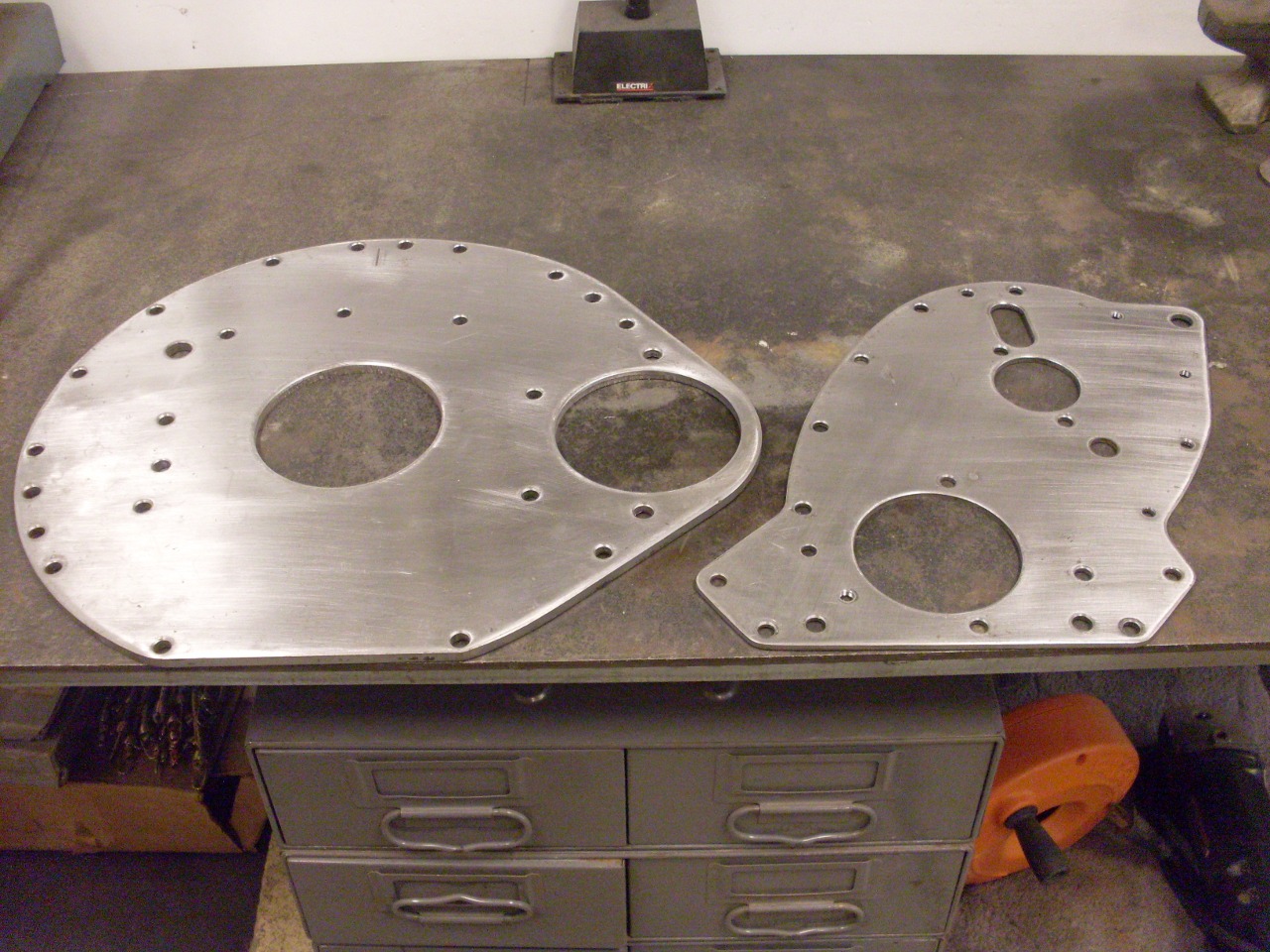
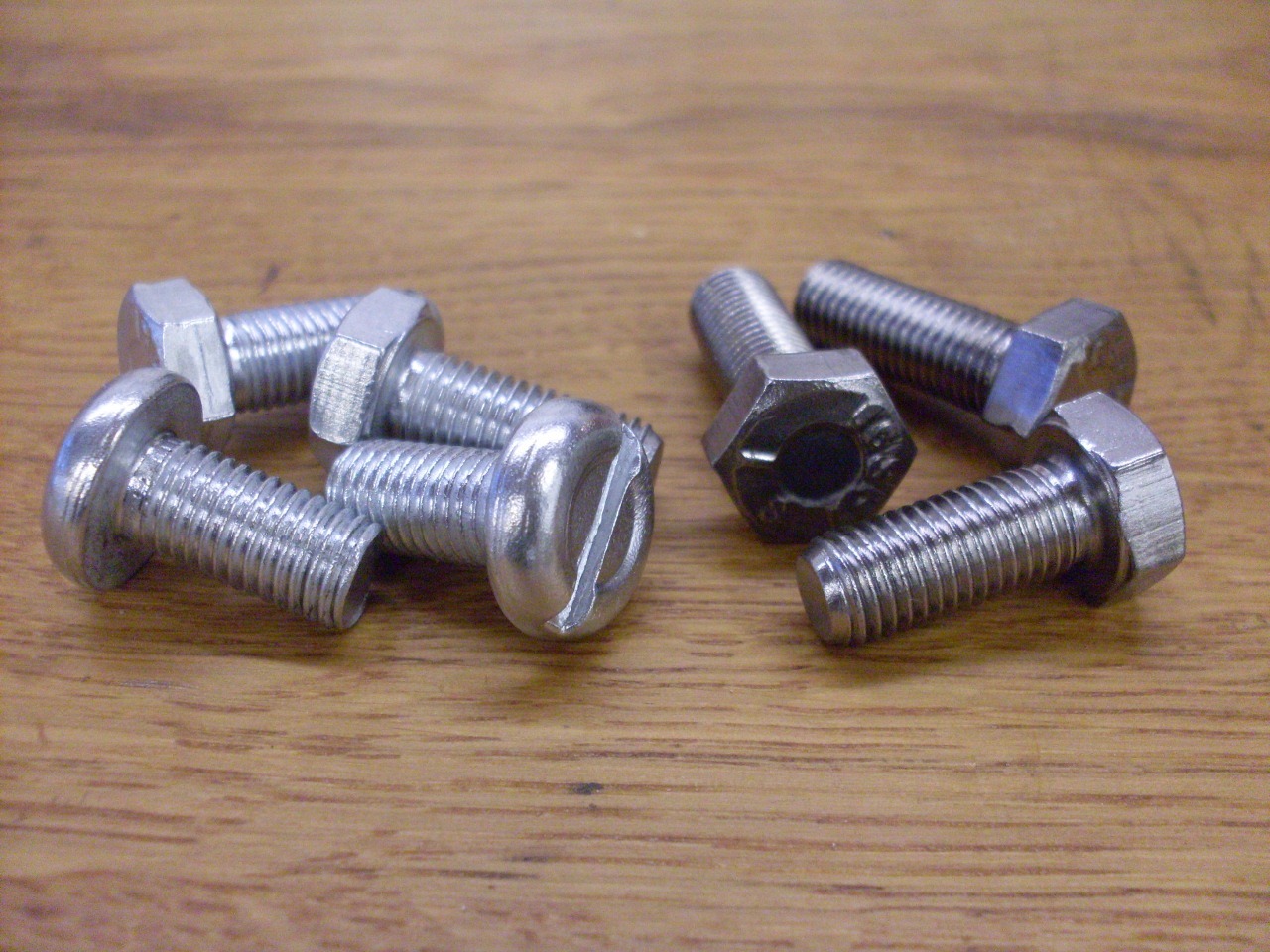
The
four screws on the left in the first pic are the ones that go along the
bottom of the front plate. They are exposed to the environment,
so I replated them. The other three are inside the timing cover,
so plating isn't necessary. I re-use original hardware when I
can, except for lock washers and lock nuts.
I
don't have the cam yet, so I can't do the timing gears or cover.
I put in all the screws hold the plate flat against the block
(and so I don't lose them).
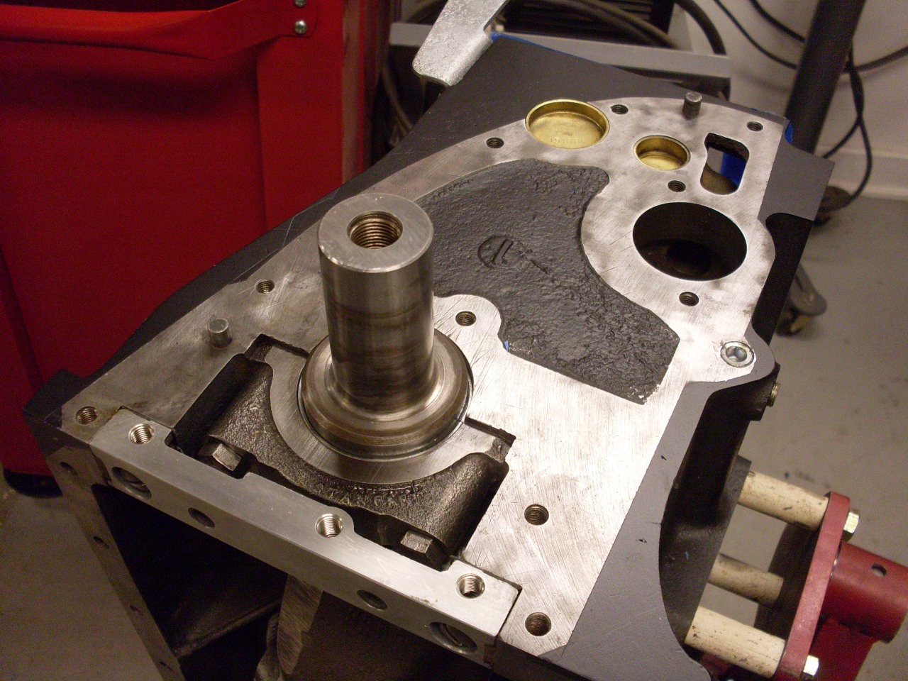
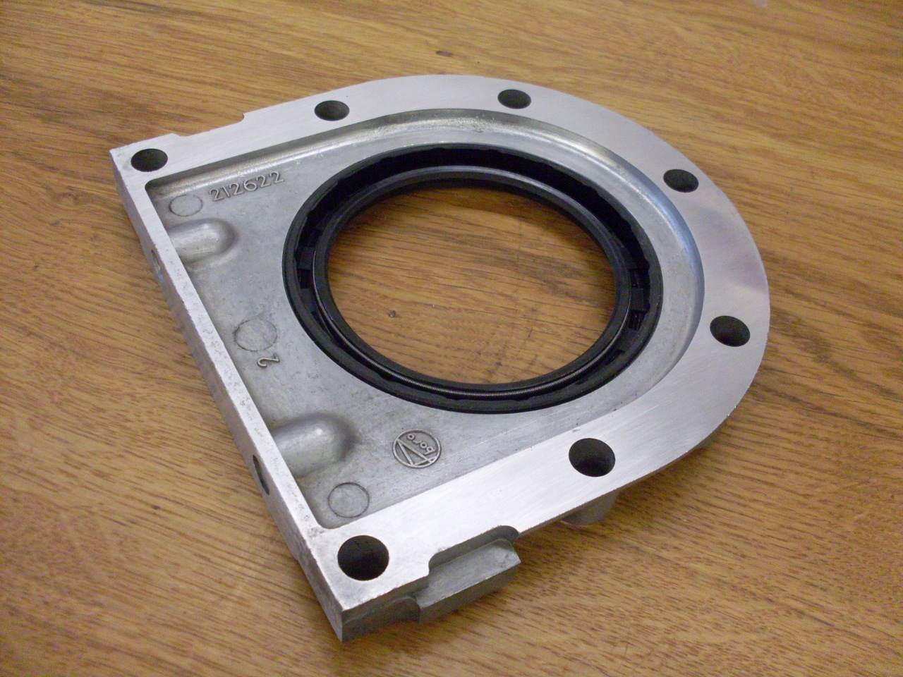
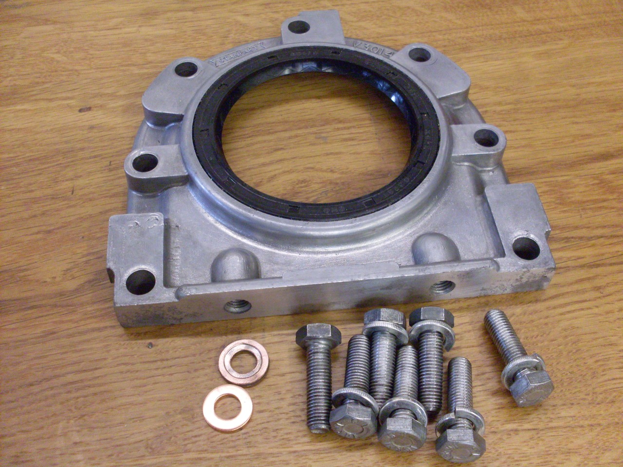
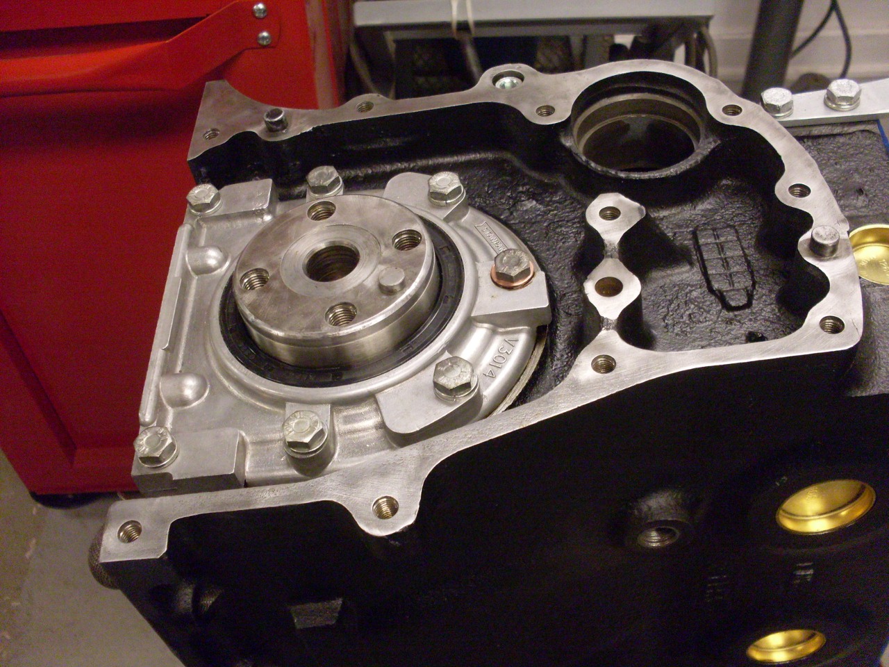
At
the other end of the block, we have the rear seal housing. It
gets a new rear seal, of course. The housing was linished a bit
just to make sure it was flat. The top fastener on the housing
goes into a hole that opens into the crank case, so it needs a
provision to make it fluid tight. Triumph's answer was a copper
washer. I used a new washer, but copper in this kind of
application needs to be annealed before installation. Heating it
to red heat then letting it cool accomplishes this.

Before
the rear seal can be installed, there is an important item that needs
some attention. The rear main seal rides on this feature at the
rear end of the crankshaft. Near the small flange is a
groove that was worn by the previous seral. This is not a good
sealing surface for the new seal.
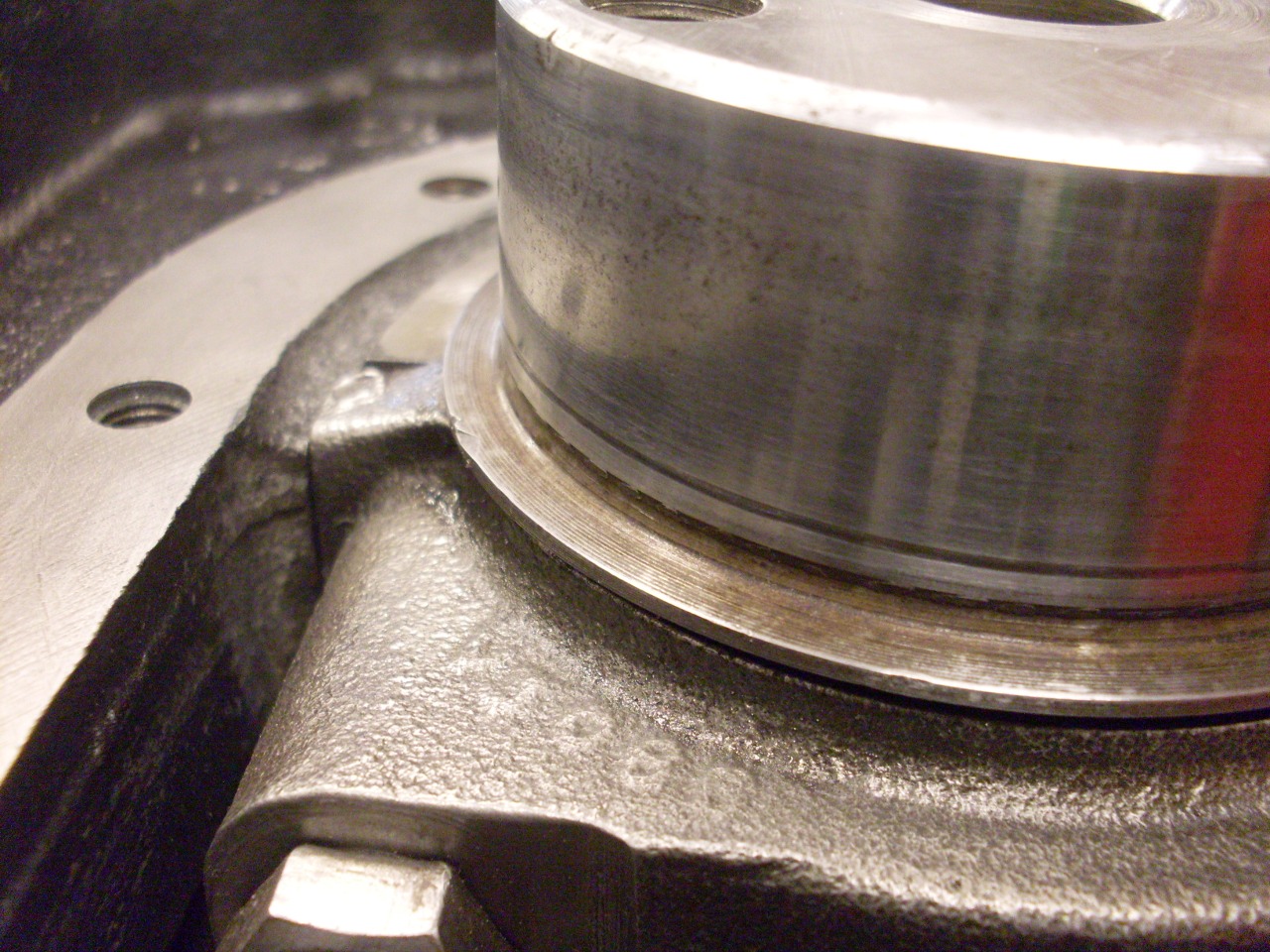
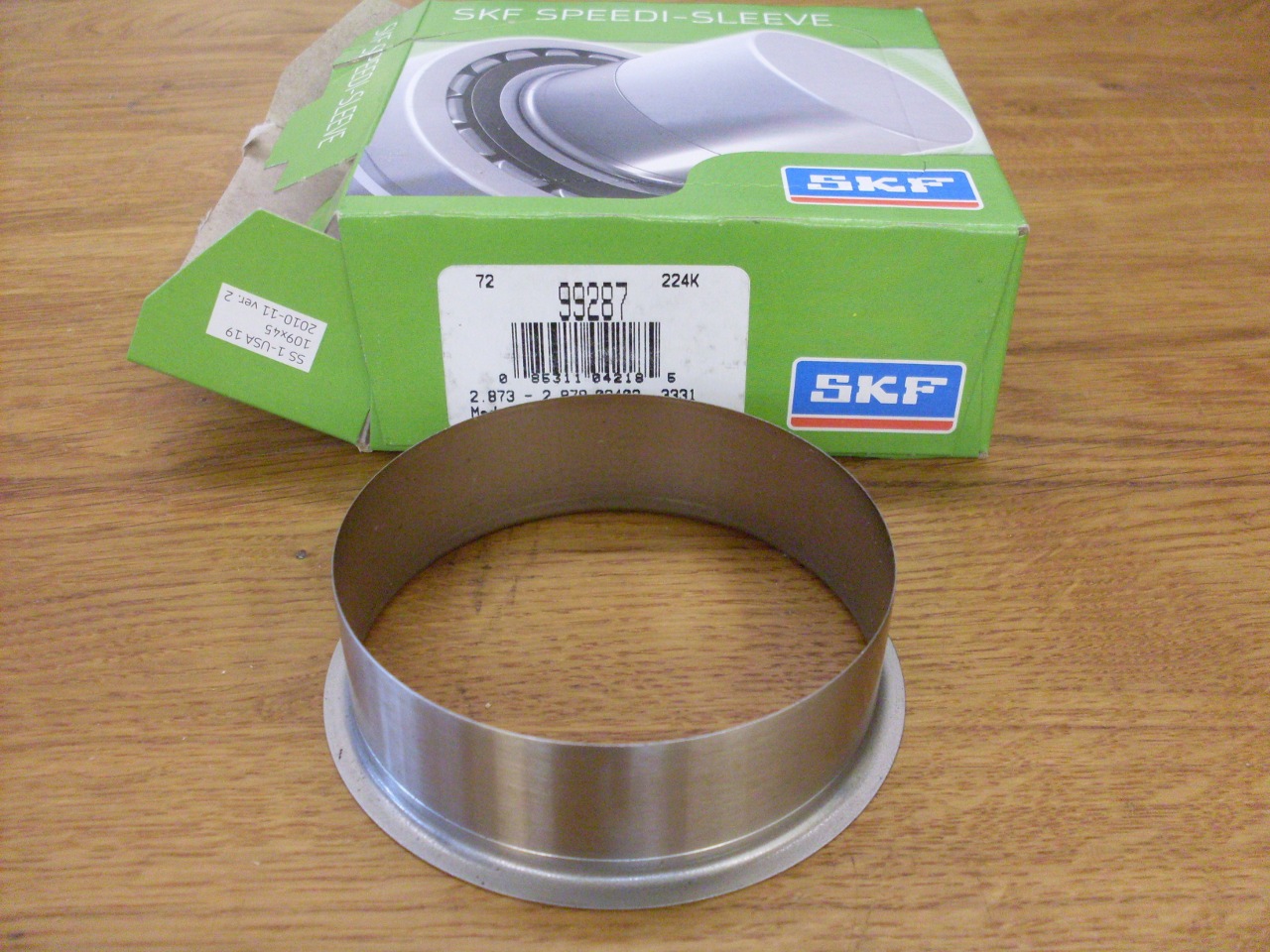
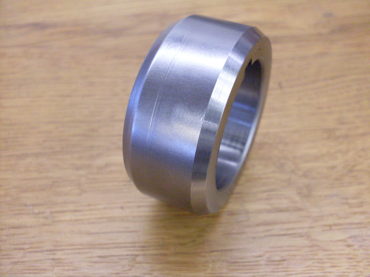
One
common way to mitigate this problem is to put a thin sleeve over the
crank end for the new seal to ride on. This paricular one is
called a Speedi Sleeve, but there are other brands available. The
sleeve is very slightly smaller than the shaft, and has to be driven
on. I put a little sealant inside th there is no leak path there.
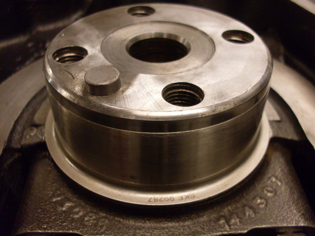
The rear main installed and housing torqued down.
It
occurred to me after I did this that there may have been a simpler and
cheaper alternative to the Speedi Sleeve. The rear seal housing
doesn't have a positive locating step or flange on its ID.
Because the housing is thicker than the seal, there is
probably at least a 1/8" range for the position of the seal. It
might have been possible to find a position for the seal in the housing
that would put the seal lip on an unworn part of the crank. I'll
have to remember this for next time.
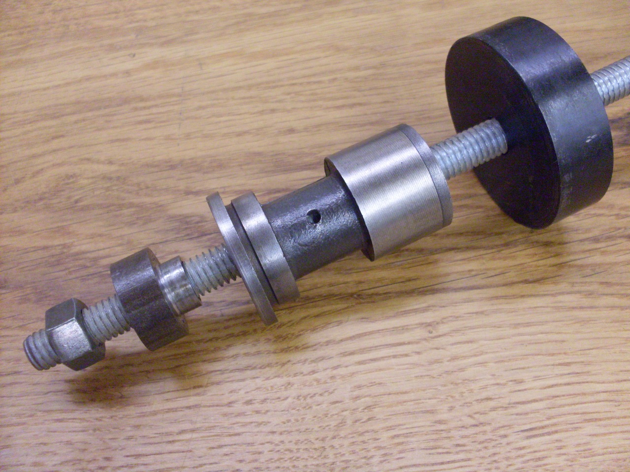
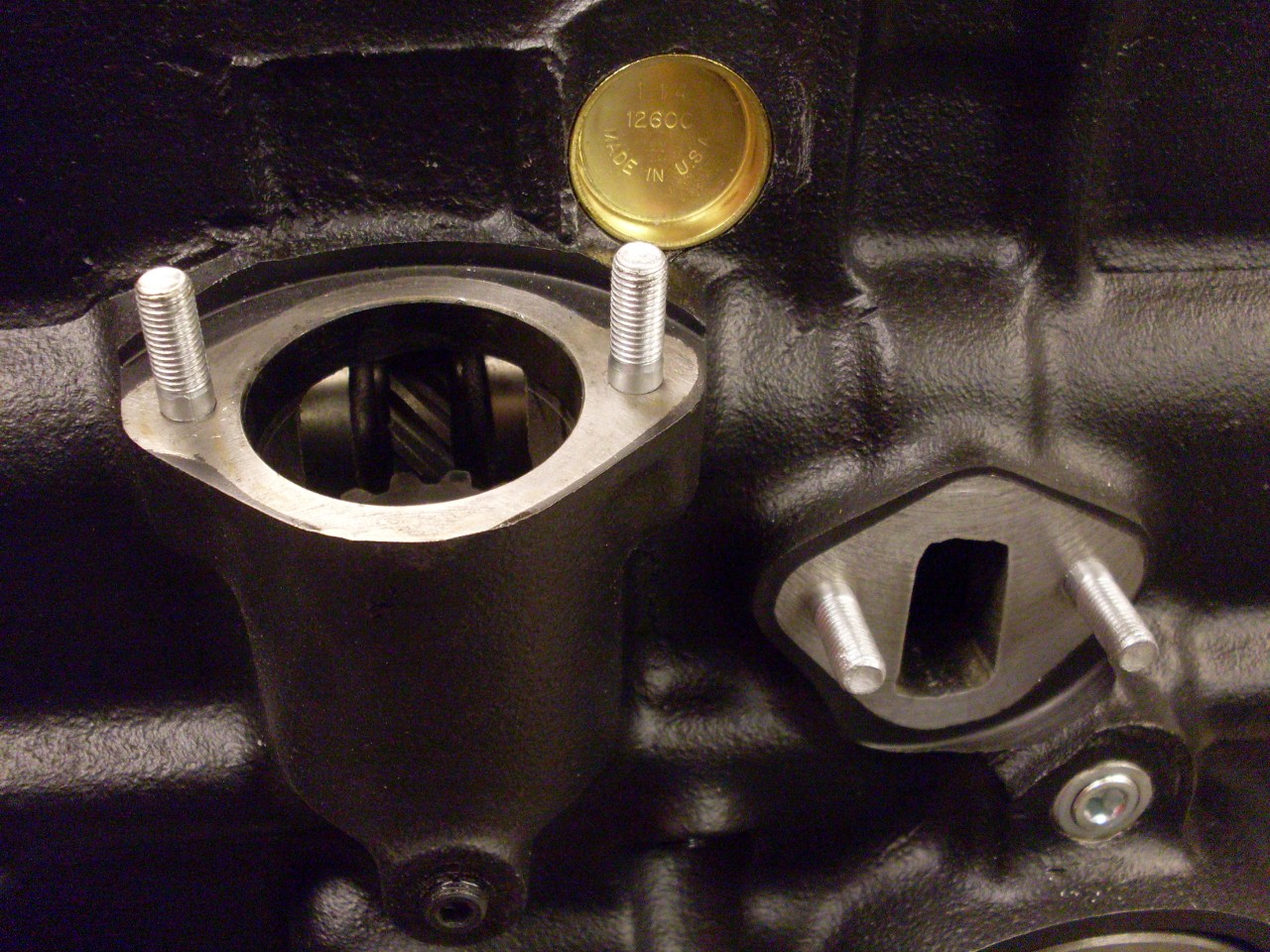
A few more odds and ends.
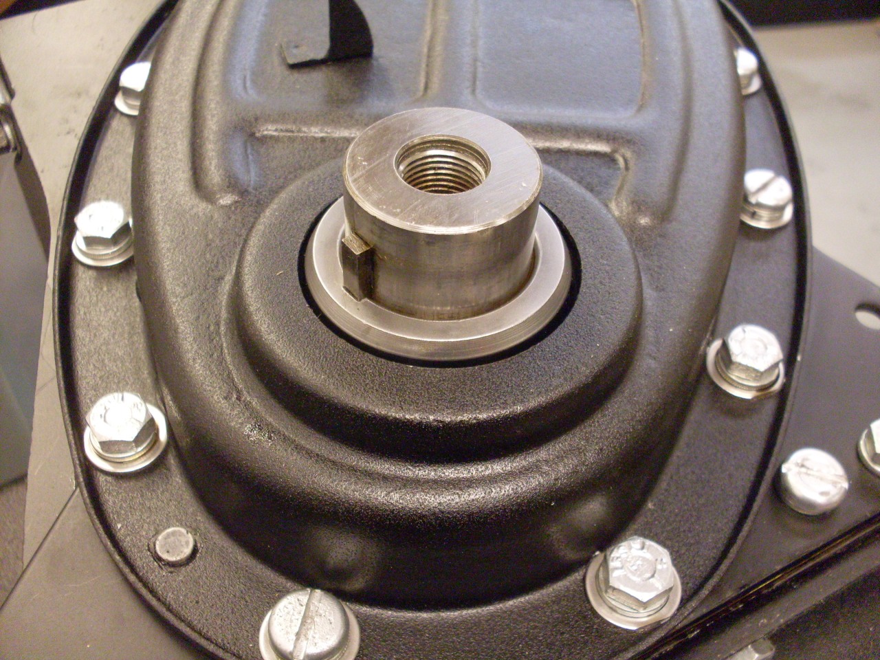
One is the oil pump drive bush. This is a cast iron piece
that is pressed into the block, and carries the shaft that drives the
oil pump. This is a sort of fragile part that is hard to
replace, so I wanted a safe way to install it. Rather than
pounding it in with a drift as the manual suggests, I fashioned a press
that would slowly pull it into place. Worked llike a charm.


Then installed the oil pump:

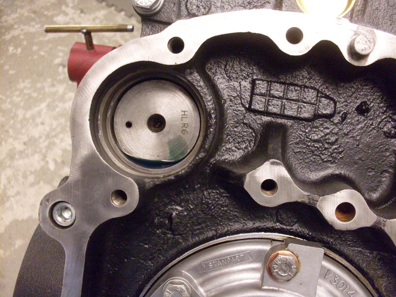
Feb. 6, 2014:
The new camshaft finally arrived (the one in the back):
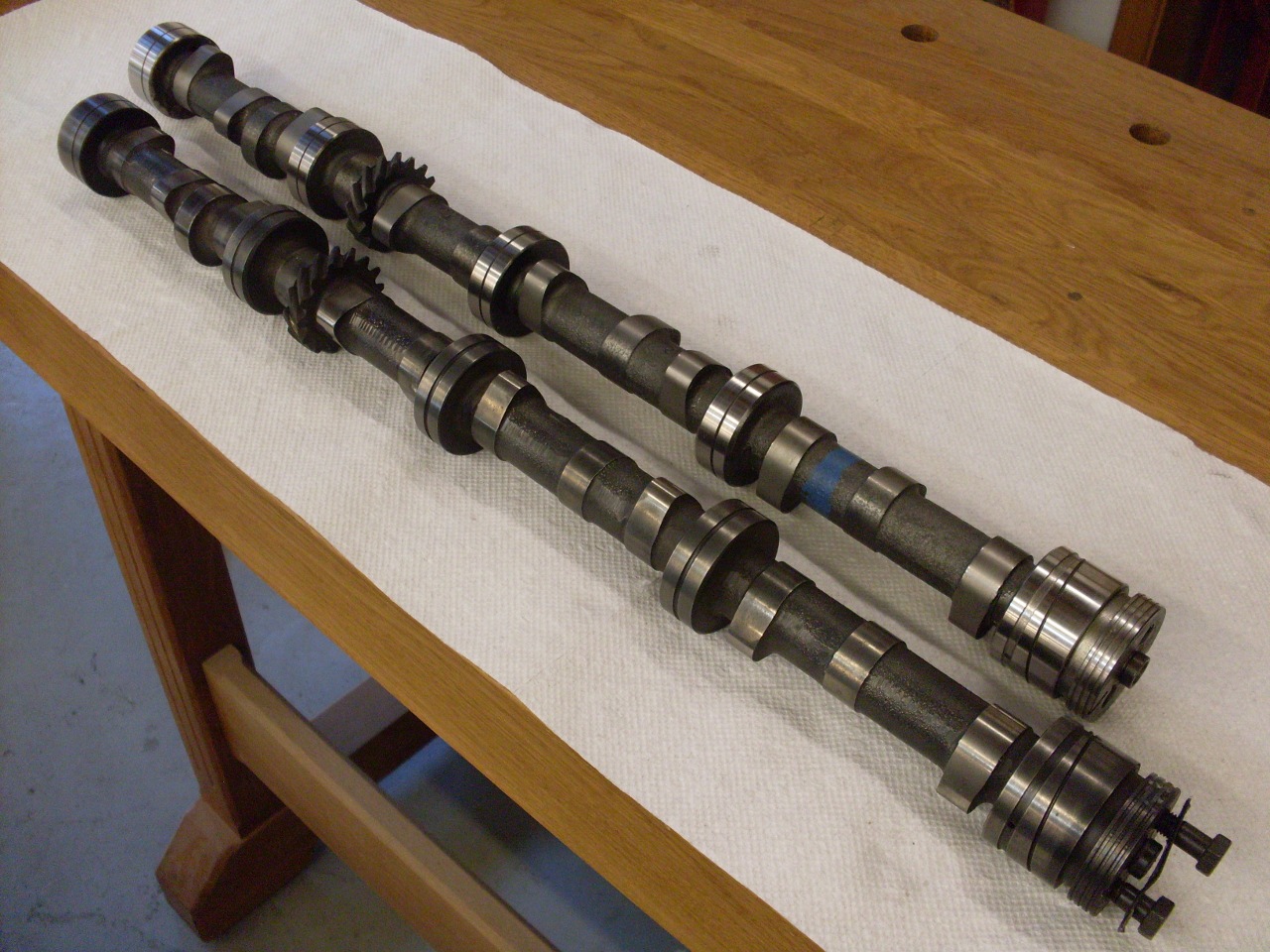
The
cam went in without incident until I tried to torque down the keeper.
I slid my old cam keeper into the slot of the new cam and
measured the clearance, which would translate into cam end float, and
it was 0.011" or so--out of spec range of 0.004-0.008. So I
got a new keeper. With the cam installed with the keeper screws
finger tight, I got about 0.005" float. This was fine with me,
but when went to tighten the keeper down, the cam bound up and wouldn't
turn. So into investegative mode I went. First, the new
keeper was significantly thicker than the original--0.189" vs 0.181".
The new one also didn't look quite as nicely finished as the
original. But on the other hand, the clearance in the cam groove
was OK in it's free state. It was only when under the stress of
tight fasteners that the binding occurred. Eventually, I was able
to determine what was happening. When the
fasteners were tightened, the keeper was distorting. It's mid
section
was arching up by a few thousandths.

In
retrospect, this isn't too surprizing. The keeper is being
tightened down to the block's front plate, which appears to be a piece
of ordinary cold rolled steel that's been worked quite a bit--certainly
not a precision surface. Under the plate, which is only about
0.160" thick is a 0.031" gasket, which of course has a little
resiliency. Tightening the keeper screws could easily distort the
surface of the plate a little. The distortion can get magnified
through lever action to produce what I was seeing--when the fasteners
were tight, the keeper clearnce was 0.005 near the fasteners, and zero
in the middle. This explained one other thing--the only evidence
of wear on the old keeper was right in the middle, where the buckling
was happening.
I wasn't sure I could do much about the arching
of the keeper, but I could allow for it with a thinner plate. As
luck would have it, my old, thinner plate worked just fine.
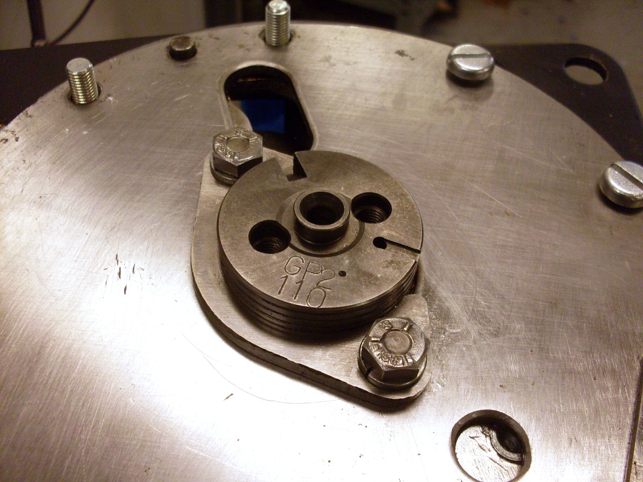
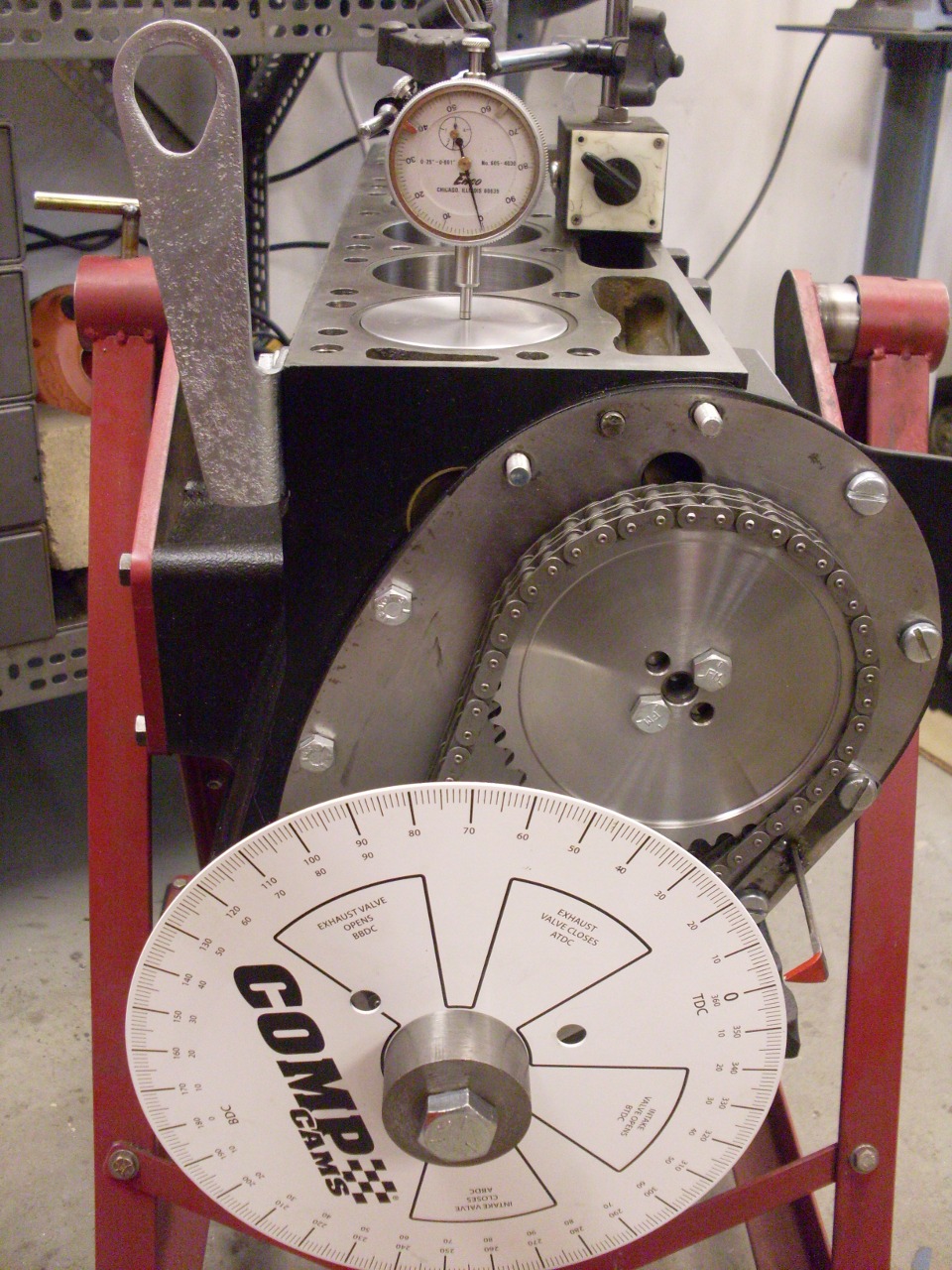
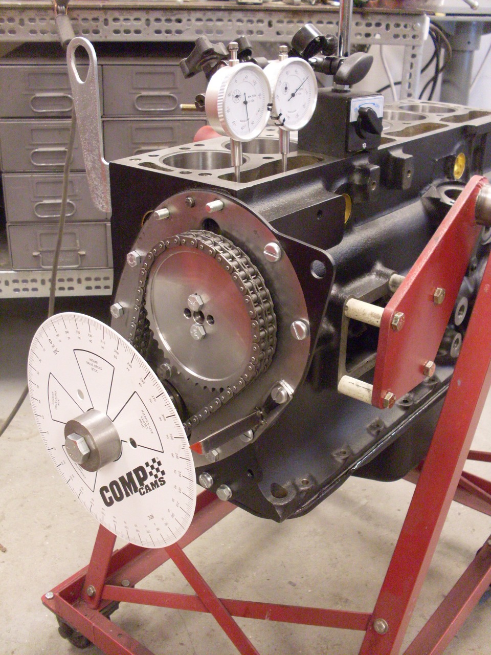
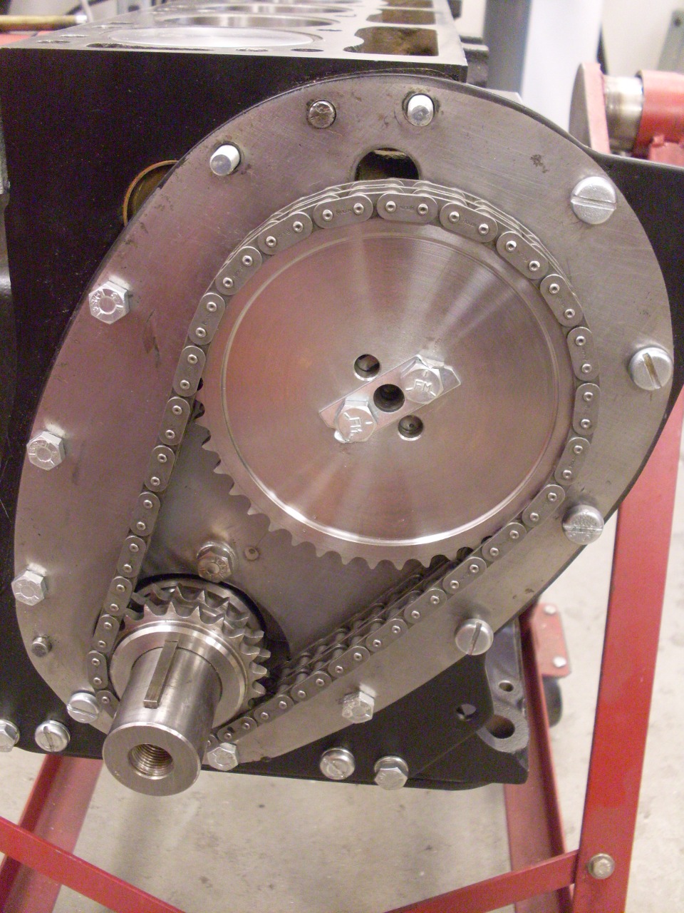
Next
up was cam timing. There are plenty of very good tutorials on TR6
cam timing on the web, so I won't get too far in the weeds here, but
rather just show some of the setups I used.
The
GP2 is a symmetrical cam. This means that the intake and
exhaust lobe profiles are symmetrical around crank TDC for nominal cam
timing. This makes possible a way to time the cam by setting the
point at which the intake and exhaust lifters are at the same height
(with the exhaust lifter on the way down, and the intake lifter on the
way up) to occur at crank TDC. So the process is to first
know where crank TDC is, second, know where the cam "crossover" point
is, and arrange the timing gears and chain such they happen at the same
time.
First the timing gears need to be trued up by making sure
their front surfaces are in the same plane. Shims are put under
the crank gear to move it up. Mine took only one of the two
original 0.006" shims.
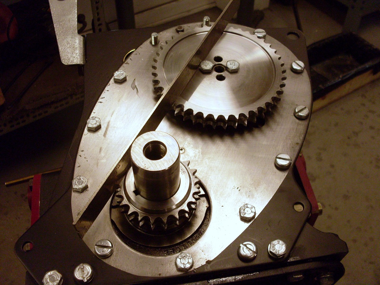
I
made a sturdy pointer to screw onto the front plate. I've seen
pics of foot-long pieces of baling wire wrapped around a head bolt used
as a pointer. The process can be intimidating enough without
throwing in more uncertainty.
To
find TDC, I used a dial indicator on the #1 piston. Since the
vertical movement near TDC is very insensitive to crank movement, a
good way to do this is to tighten a degree wheel on the crank (at a
random position to start), and note the degree readings for a certain
piston position on both sides of TDC. TDC will be halfway between
these readings. Set the crank there, loosen the degree wheel,
move it to TDC, and tighten.
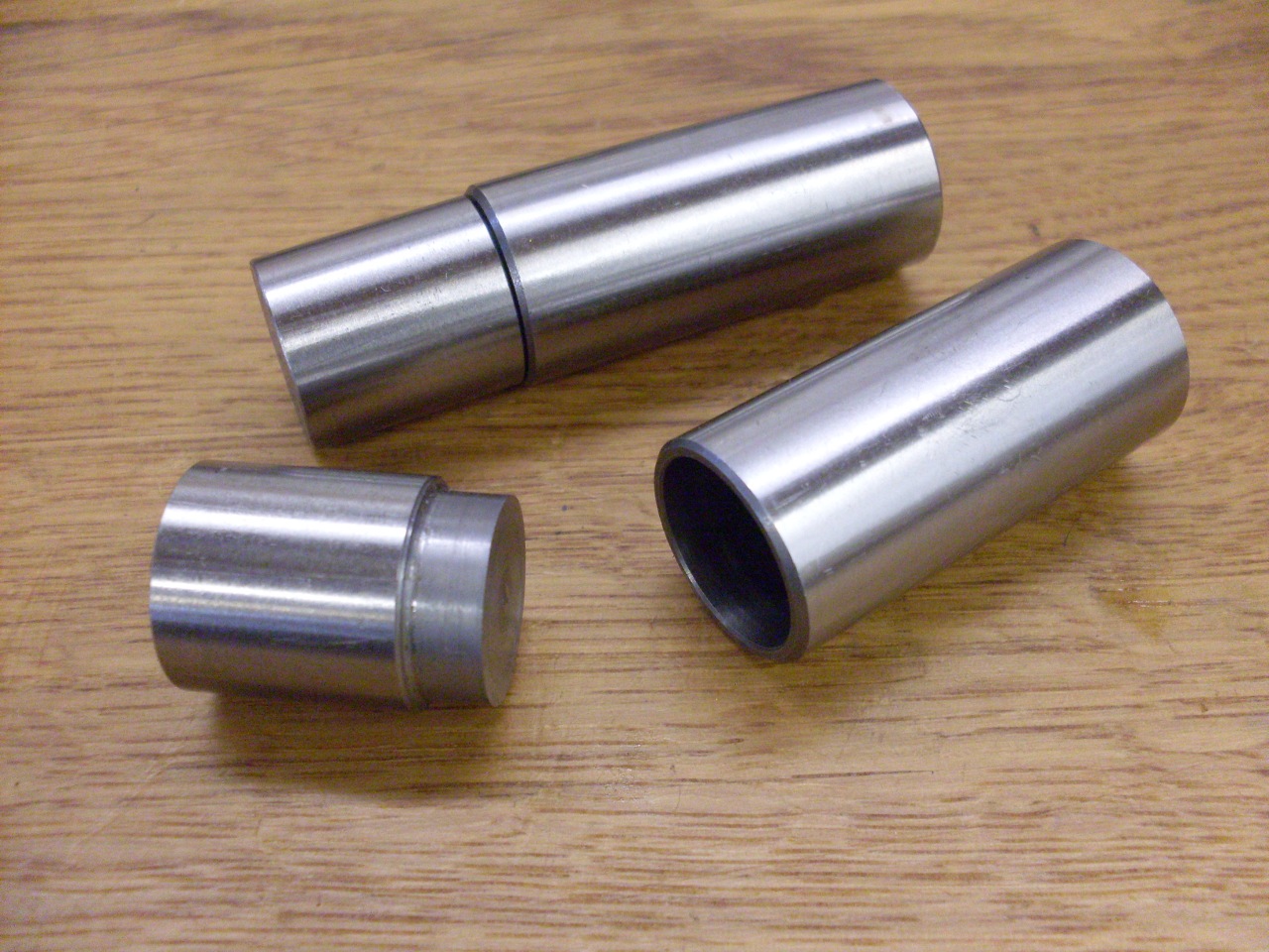
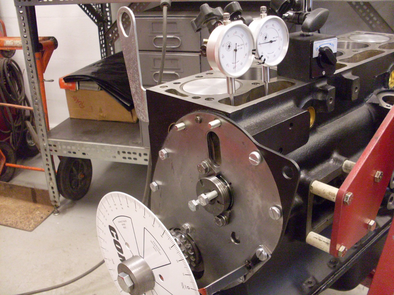
To make finding the cam crossover point a little easier, Imade these little slugs that fit nicely into the top of the lifters.
Then
I positioned two dial indicators on the slugs and set the indicators to
zero at the lifters' lowest positions. Once I got
comfortable with what was happening on the indicators when I turned the
cam, it was easy to see where the crossover point is--same reading on
the indicators, but with one increasing, the other decreasing.
The
last part was really the trickiest--getting the chain on so that the
crank and cam are synchronized. On each trial--and it took
several--with the chain on, I turned the crank until the cam got to the
crossover, and then I noted the crank degree reading, which should
nominally be TDC. If it was way off, I had to figure out how many
teeth which way to shift the cam wheel in the chain.
Since
there are 42 teeth on the cam wheel, each tooth represents about 8.6
degrees at the cam, or double that at the crank (and the degree wheel).
This suggests that on a bad day, the cam timing may be impossible
to set any closer than 8.6 degrees from TDC. It's actually not
quite that bad. There are two pairs of holes in the cam wheel 90
degrees apart, so shifting to the other pair will move the cam 1/4
turn, or 10.5 teeth. The option to use that extra 1/2 tooth means
that on a bad day the cam may not be capable of getting closer than 4.3
degrees to TDC.
It turns out that these errors may not be
that important except for racing. In fact many builders
intentionally set the cam timing a few dergrees early or late for the
effects it yields to the torque curve.
As a cross check,
I rotated the crank and noted the point on the degree wheel when the
intake and exhaust lifters were showing 0.050" lift both on opening and
closing. I compared these numbers to those on the cam datasheet.
My end setting was a cam timing about three degrees BTDC.
Note
that I used the cam lobes on the
#1 cylinder for this process. This finds TDC for the
exhaust/intake
stroke for that cylinder. Well, TDC is TDC for the crank, but the
cam, which turns half as fast, makes the distinction between
exhaust/intake and compression/power TDC. Many tutorials say to
use the lobes for cylinder 6 to
find cylinder 1 TDC. This obviously works, since cylinders 1 and
6 share the same crank TDC. The advantage is it determines #1 TDC
for the compression/power stroke, which is the reference for
distributor timing. Since I'm not setting up my distributor right
now, it made no difference, and it was a little easier having all the
indicators close to the degree wheel.
Took off all the measuring gear, and now I think I have a timed engine.
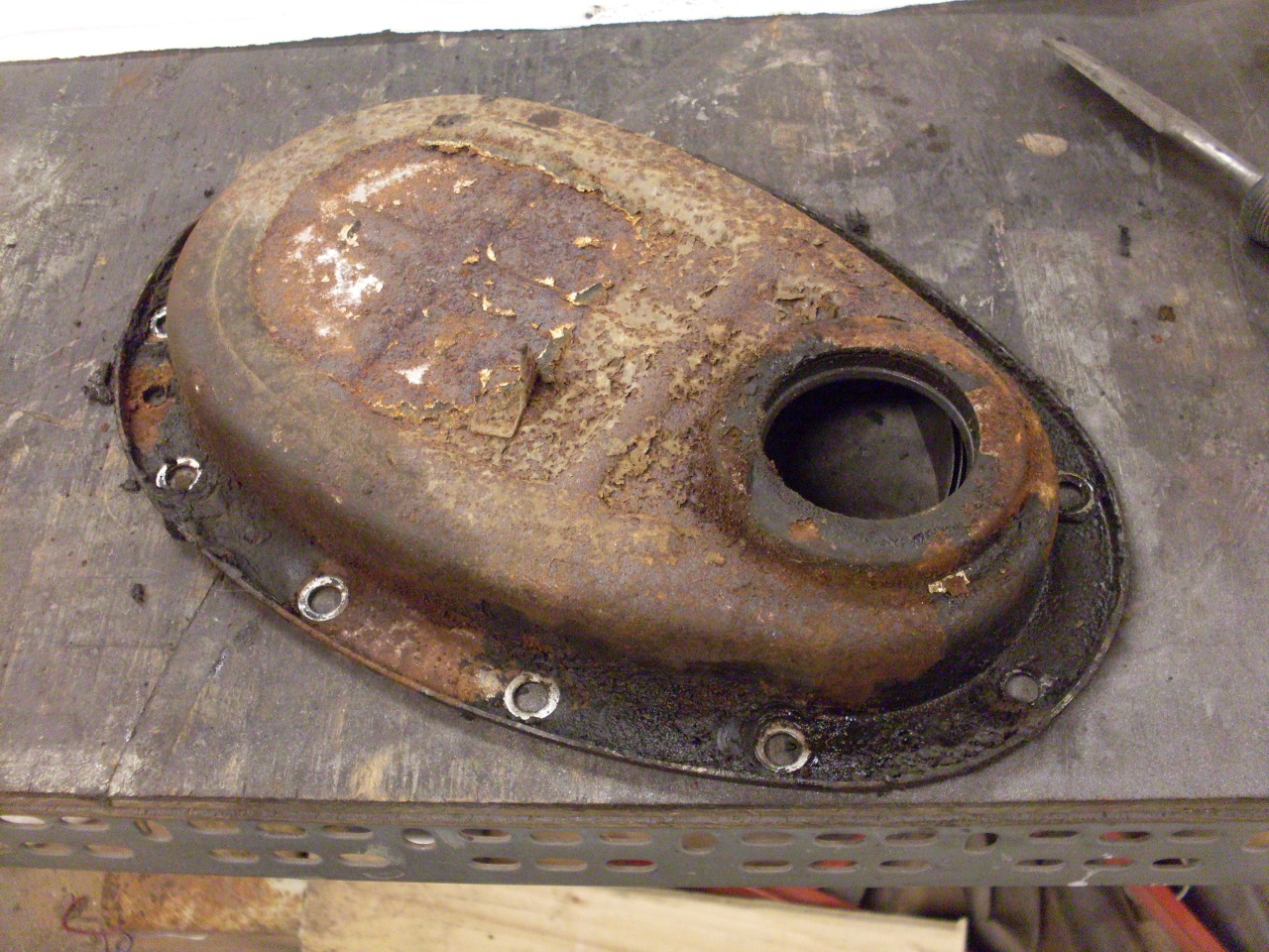
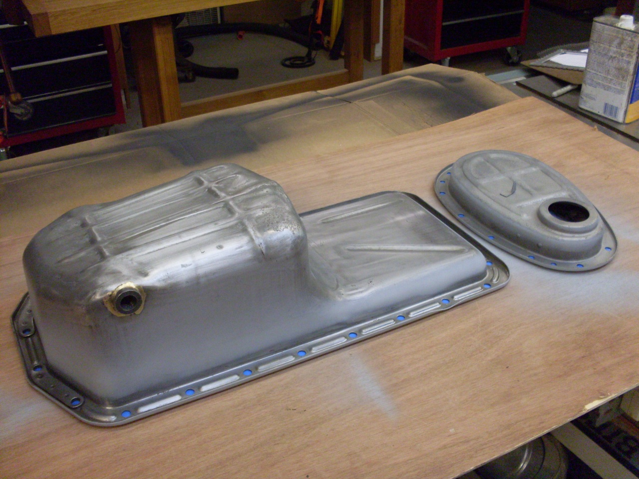
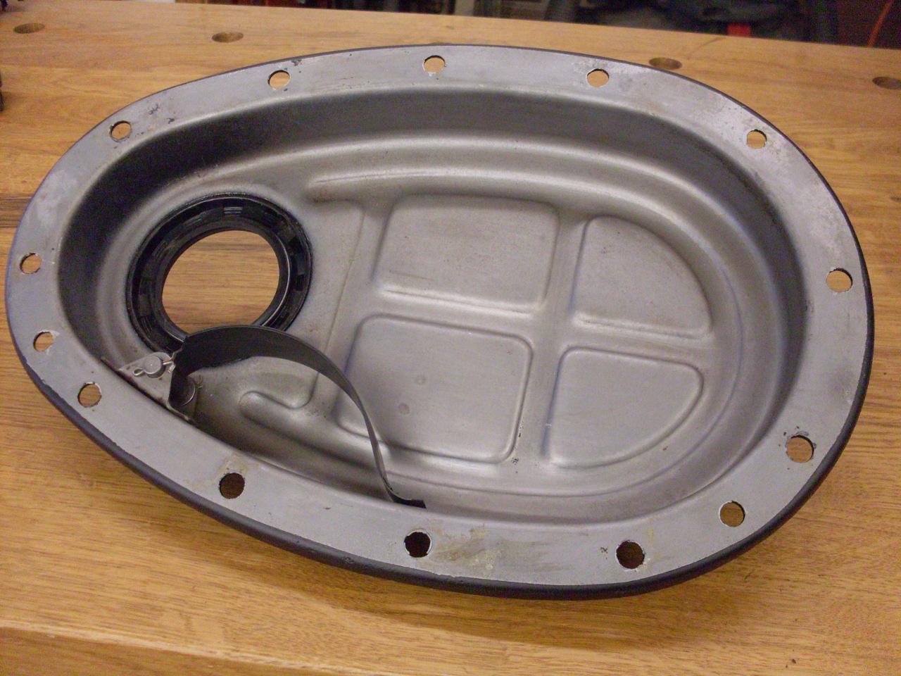
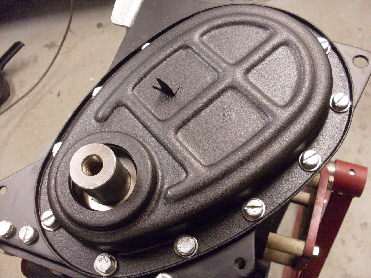
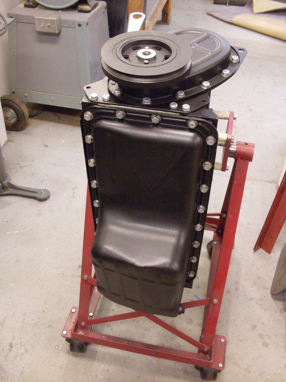
Cleaned
up, primed, and painted the oil pan and timing cover. The timing
cover was pretty severely rusted, and removing the rust left some deep
pits. I tried a heavy bodied filler primer to try to hide most
of them.
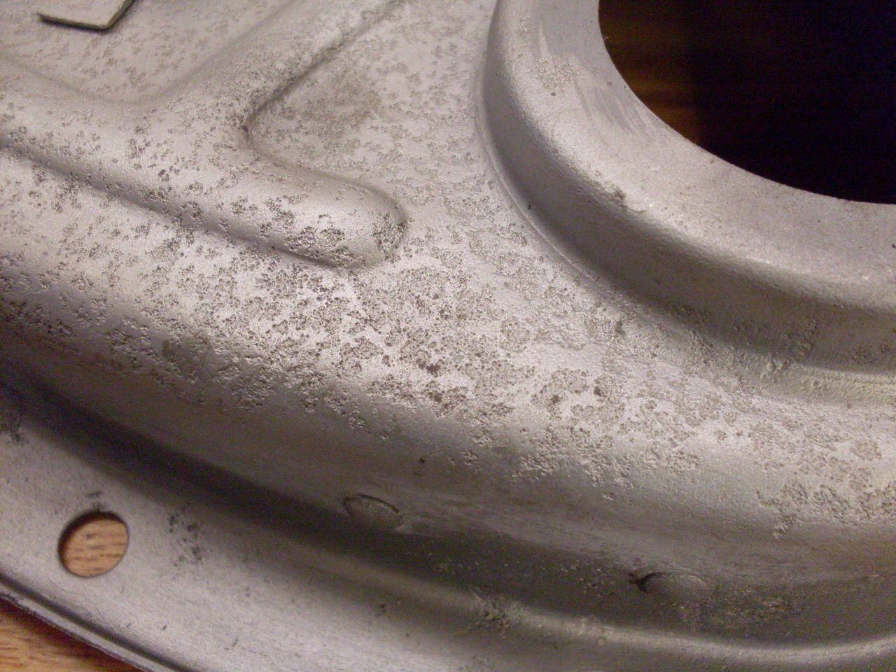
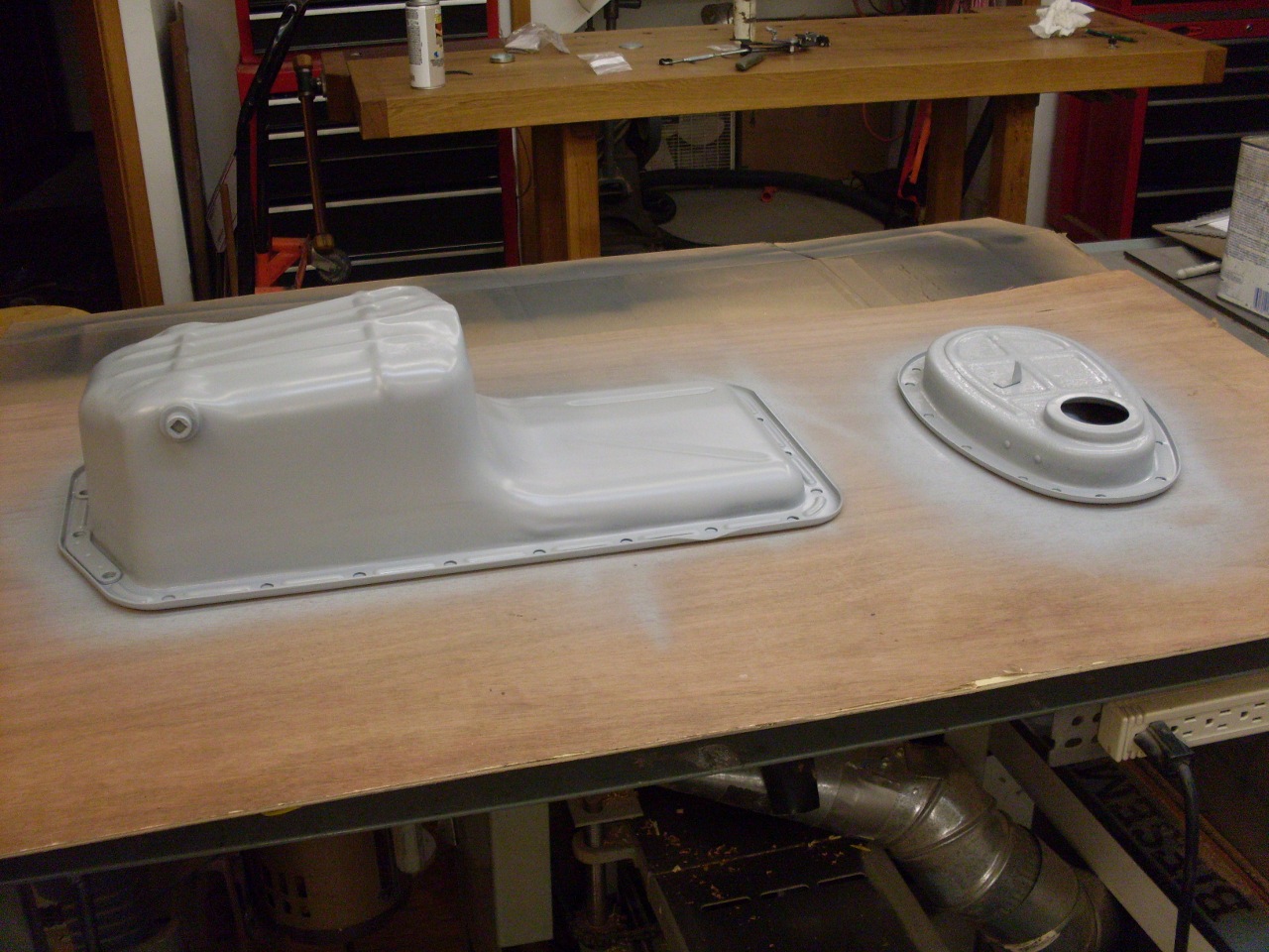
After
the primer-filler and black engine paint, some of the pits were still
showing on the timing cover, so I shot on a coat of black textured
paint sold for truck beds and such. It is claimed to be very
abrasion resistant. I think it looks cool, and it really hides
the pitting. The second pic shows the sump painted with engine
paint, and the replated original hardware. I liked the finish on
the timing cover so much, that I later sprayed it on the sump, too.
.
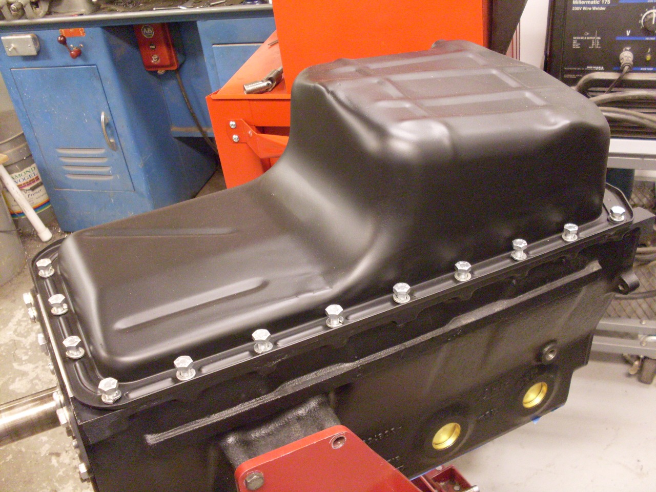
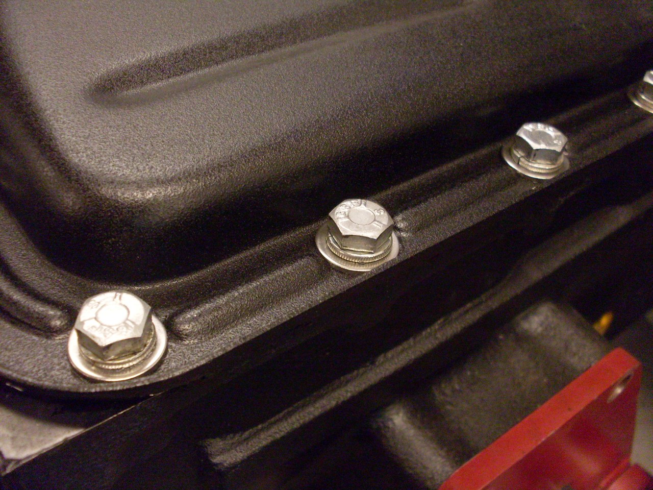
I
put some stainless flat washers under the sump hardware both to spread
the pressure a little, and to keep the lockwashers from breeching the
paint.
The
original timing chain tensioner was pretty grooved, so I reluctantly
used the new repro unit. Installed a new front seal, too, of
course.
Mounted
the timing chain cover. Some of the fastener holes for the cover
(and the sump, too) open into the crankcase. On these, I put a
thread sealant.
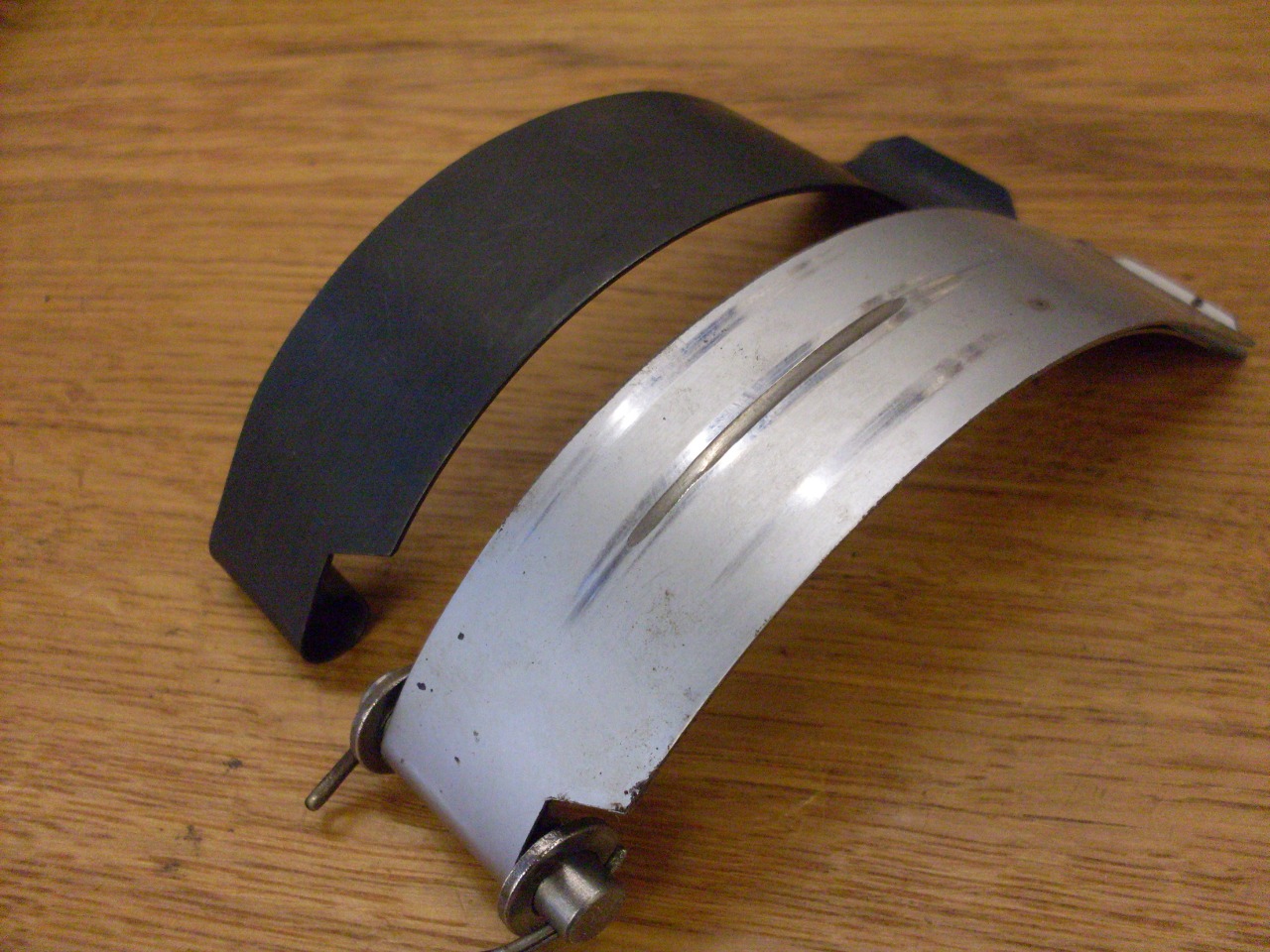
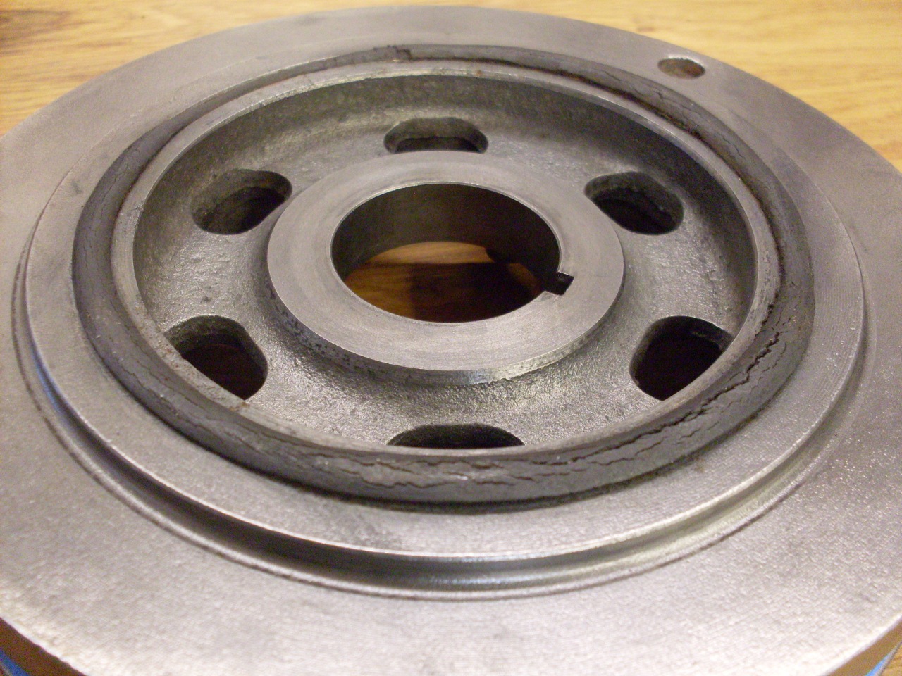
There
is a spacer that runs on the crankshaft nose that the front oil seal
seats on. Mine had a very slight groove where the old seal wore
into it. Rather than getting a new spacer or using a
Speedi-sleeve, I didn't see why I couldn't just reverse the
spacer. The only difference is the size of the chamfer. The
chamfer helps to smoothly insert the spacer into the oil seal, so I
made the smaller chanfer like the bigger one. Now the spacer is
totally reversible, giving a new surface for the seal.
Also,
the front seal seals the outside of the spacer, but there is no seal on
the inside. Even though it is a relatively good fit, it could be
a path for oil to bypass the seal. I put a little sealer inside
the spacer before sliding it onto the shaft.
Last
but not least--the harmonic damper. I'm not one who subscribes to
the notion that some exterior cracking of the rubber on the harmonic
damper indicates that the unit is necessarily failed or degraded.
The exterior rubber is directly exposed to a lot of things that
are toxic to rubber--oxygen, ozone, hydrocarbon vapors, hot oil, etc.
This is not the case for the interior rubber that does the
work of damping. Obviously, if a damper has slipped, or if it
appears loose or wobbly, it's bad, but exterior apperance isn't a good
indicator of the condition of the damper.
The
other thing that makes me cautious about calling a damper bad is the
quality of replacements or rebuilds available. It is considerably easier to
make a damper product look trick or blingy than it is to make it
perform adequately. Damper design is serious science, and there
is much more to it than pouring some rubber casting compound between
two pieces of metal. The tragic thing is that an ill- (or non-)
performing damper may not show any obvious symptoms to us humans, but
the crank will certainly know it. I just wonder how many
aftermarket damper manufacturers or rebuilders have done the rigorous design and
testing to ensure effective damping for a particular application.
If they don't say they have, then they probably haven't.
I'm probably going to use an electric fan, so this is as far as I need to go on the front end.
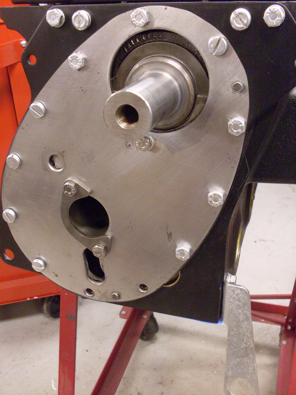
Installed
the distributor drive gear. There is a specific position for the
offset slot in the gear relative to TDC of the crank to ensure that the
distributor ends up in the right orientation so that the tach cable can
be routed easily. Since the gear teeth are helical, the gear
rotates as it meshes. The gear shaft also has to mate with the
oil pump shaft in order to seat properly. It took several tries
to get it right.

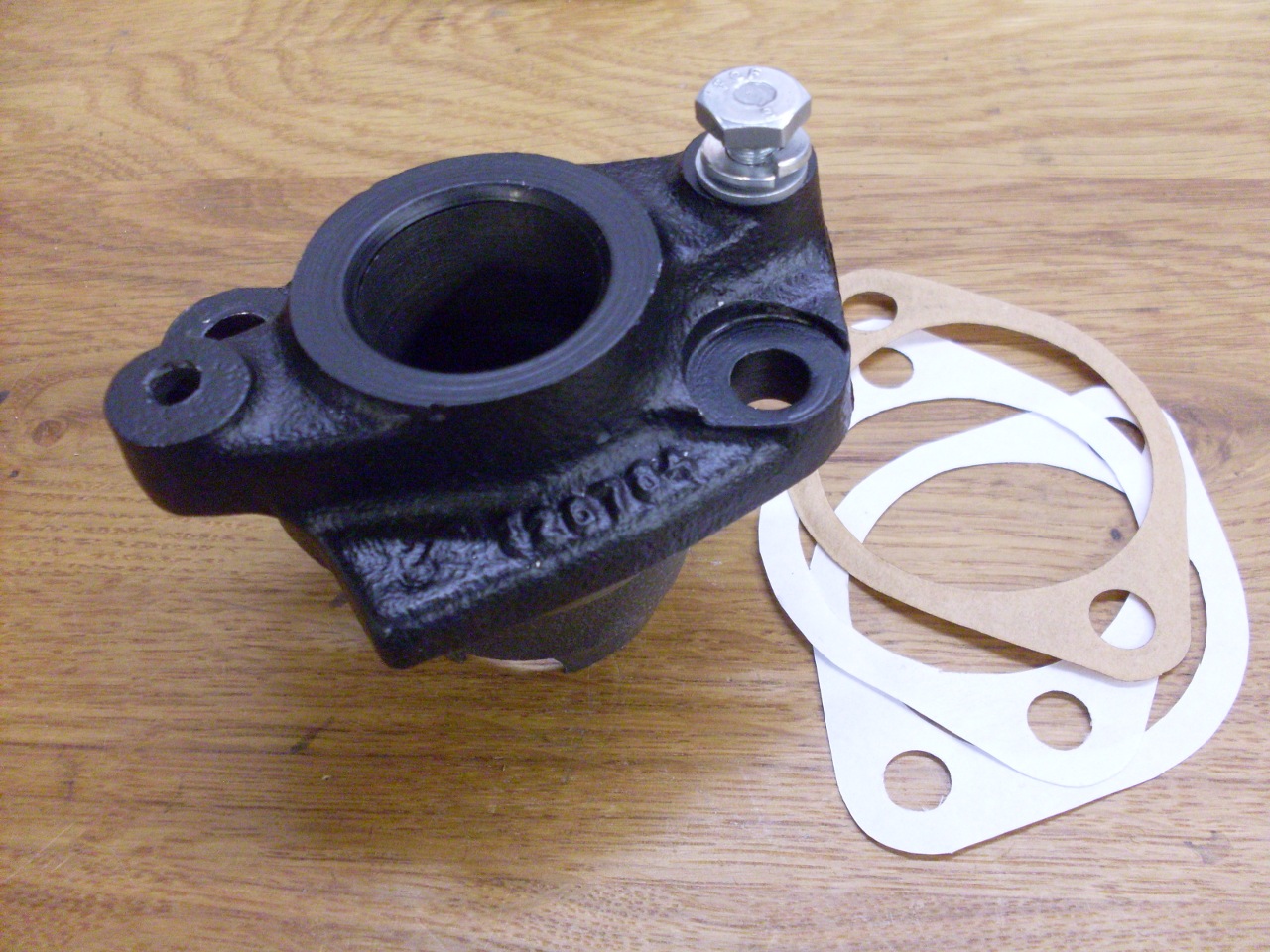
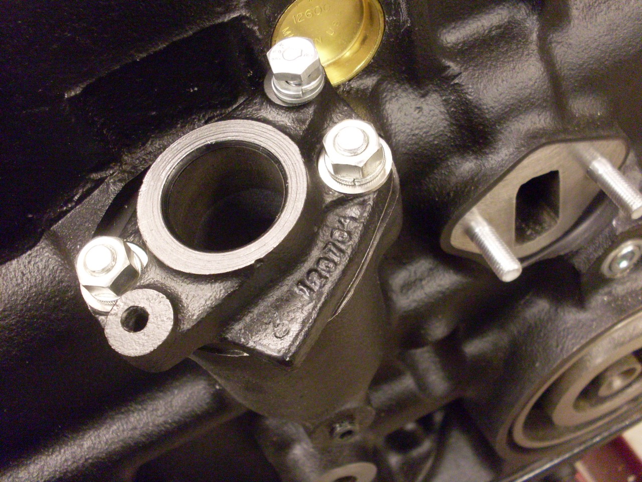
Cleaned up and replated the distributor pedestal and fuel pump mount studs.
The
clearance between the distributor drive gear and the distributor
pesestal is set by a rather odd process that involves adding a
temporary spacer, measuring a gap, and using math to figure the
necessary gasket thickness. The gaskets are actually spacers.
I didn't realize all this when I was ordering parts, so I only
had one gasket. I had to make two more out of 0.004 paper to get
the right clearance. The books don't say so, but using some care,
the final clearance can be measured with a feeler gage down the bore of
the pedestal.
Lubed up all the new cam followers and slid them in place.
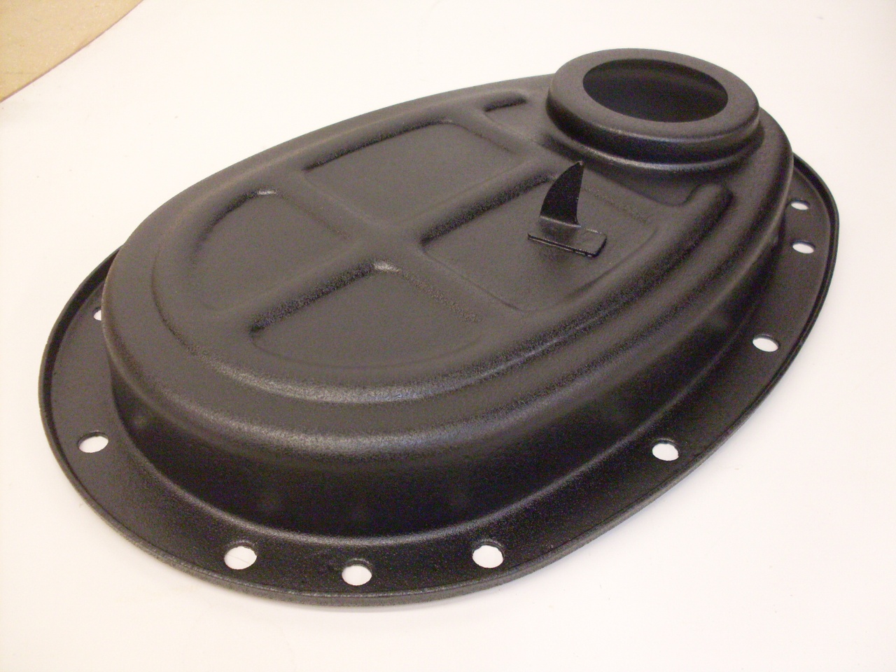
The rear of the cam gets a core plug cover.
Refurbished
the oil pressure regulator with a new spring, crush washer, and
plating. Also new plating on the plug that goes in above the
regulator.

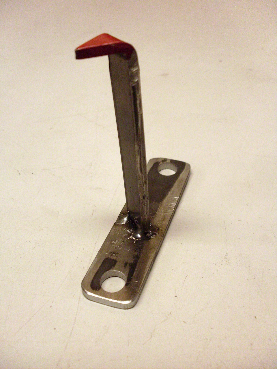
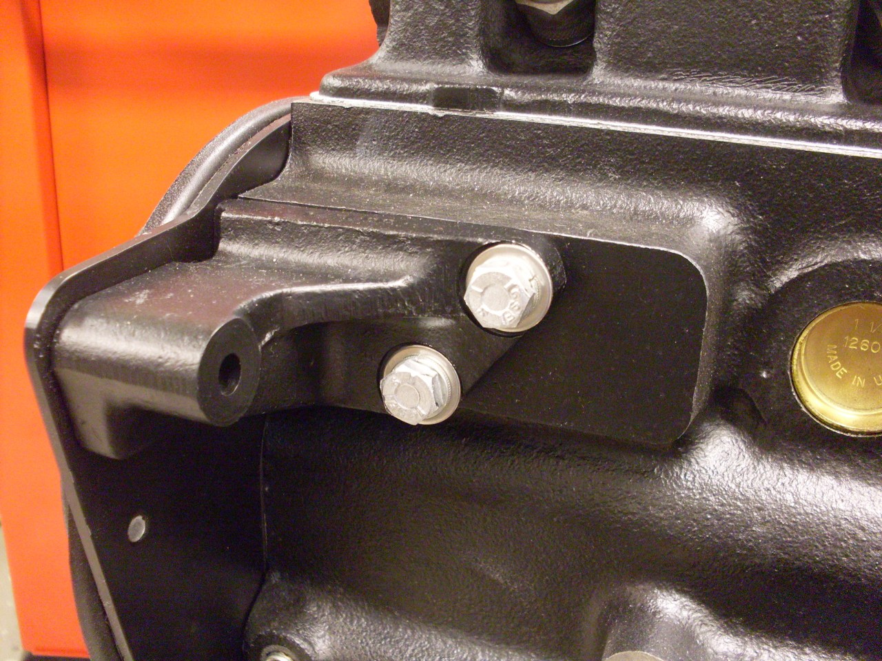
New front bracket. I forget what it's for.
Comments to: elhollin1@yahoo.com
To other pages