To my other GT6 Pages
September 11, 2022
PDWA & Plumbing
By '69, all new cars, at least in the US, had a dual-circuit hydraulic
braking system. The master cylinder actually had two pistons, each
drawing fluid from its own fluid reservoir. One piston fed the
brakes at two wheels, while the other fed the other two.
Typically, it was front brakes/back brakes. This redundancy was a
boon to safety, but by itself, it had a down side. If one circuit
failed, the brakes would still stop the car, but with reduced
effectiveness, especially in a panic situation. Thus the provision
of a device to detect and report the failure of one of the circuits.
This device, on our cars called a "Pressure Differential Warning
Actuator" or PDWA is a mechanical gadget that both brake hydraulic
circuits pass through. The PDWA has no effect on the operation of
the brake system. There is a shuttle piston inside that sees
hydraulic pressure of one circuit on one end, and the pressure of the
other circuit on the other end. In normal operation, these two
pressures should be close to equal, so the shuttle is unaffected.
If one circuit fails, the difference in pressure forces the shuttle to
one side. This actuates an electrical switch that turns on a
warning light on the dashboard.
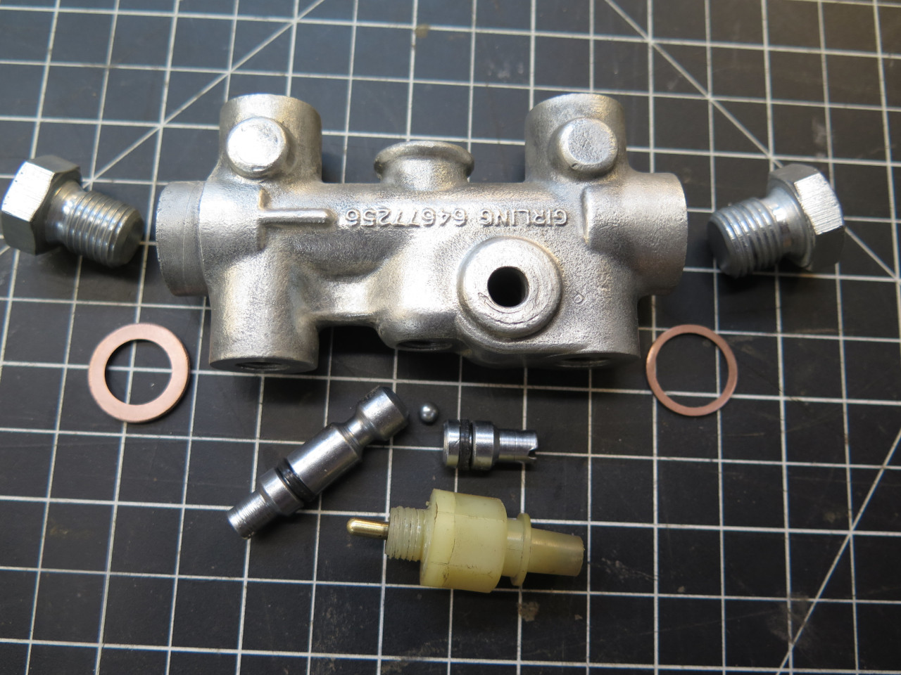
Triumphs used a number of PDWAs over models and model years. Mine was an aluminum body type.
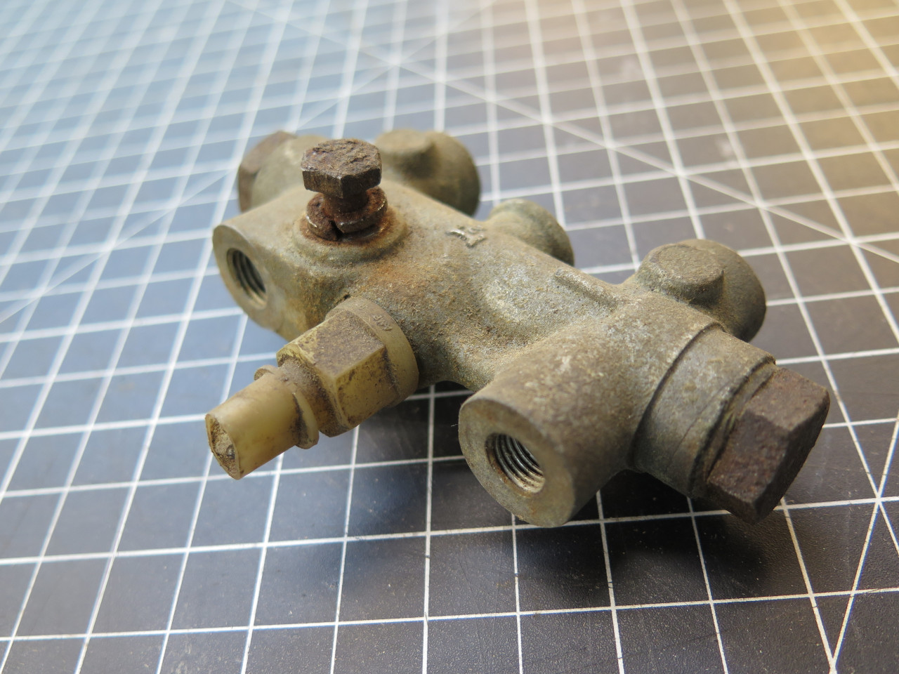
There are quite a few documents and videos on the web that show how to rebuild a PDWA, so I guess I'll just add one more.
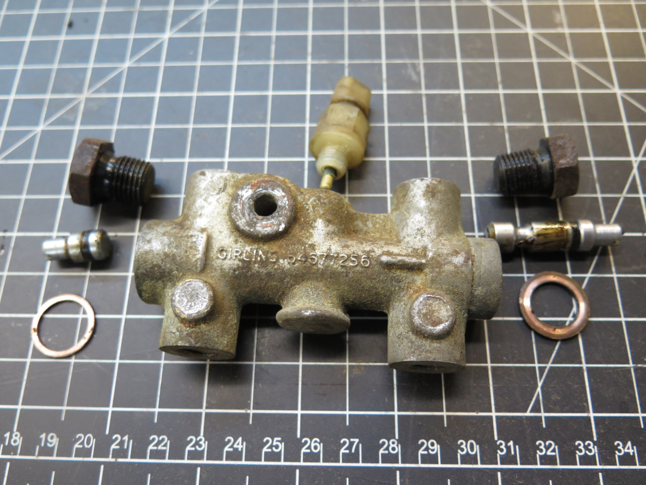
The plastic switch screws out of a hole in the center of the
device. Once the two end plugs come off, with their copper sealing
washers, the two-piece shuttle can be drawn out. There is also a
small ball bearing which at this point was still stuck in the body.
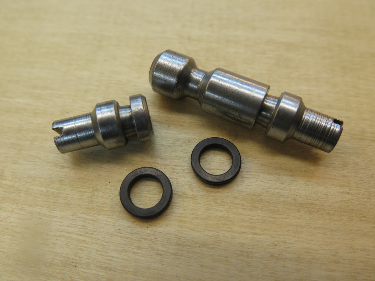
Each part of the shuttle has a square section O ring seal. They
are a common industrial size -010, but you have to be mindful of the
material they are made from. These new seals are Viton.
Viton is compatible with DOT5 silicone brake fluid, which is what I use
in my old cars.
Everything else is cleaned up. I typically re-use copper sealing
washers, but I flatten them and anneal them first. The end plugs
were pretty rusty, so they got derusted and zinc plated. The
switch didn't work at first, but some exercise and some contact cleaner
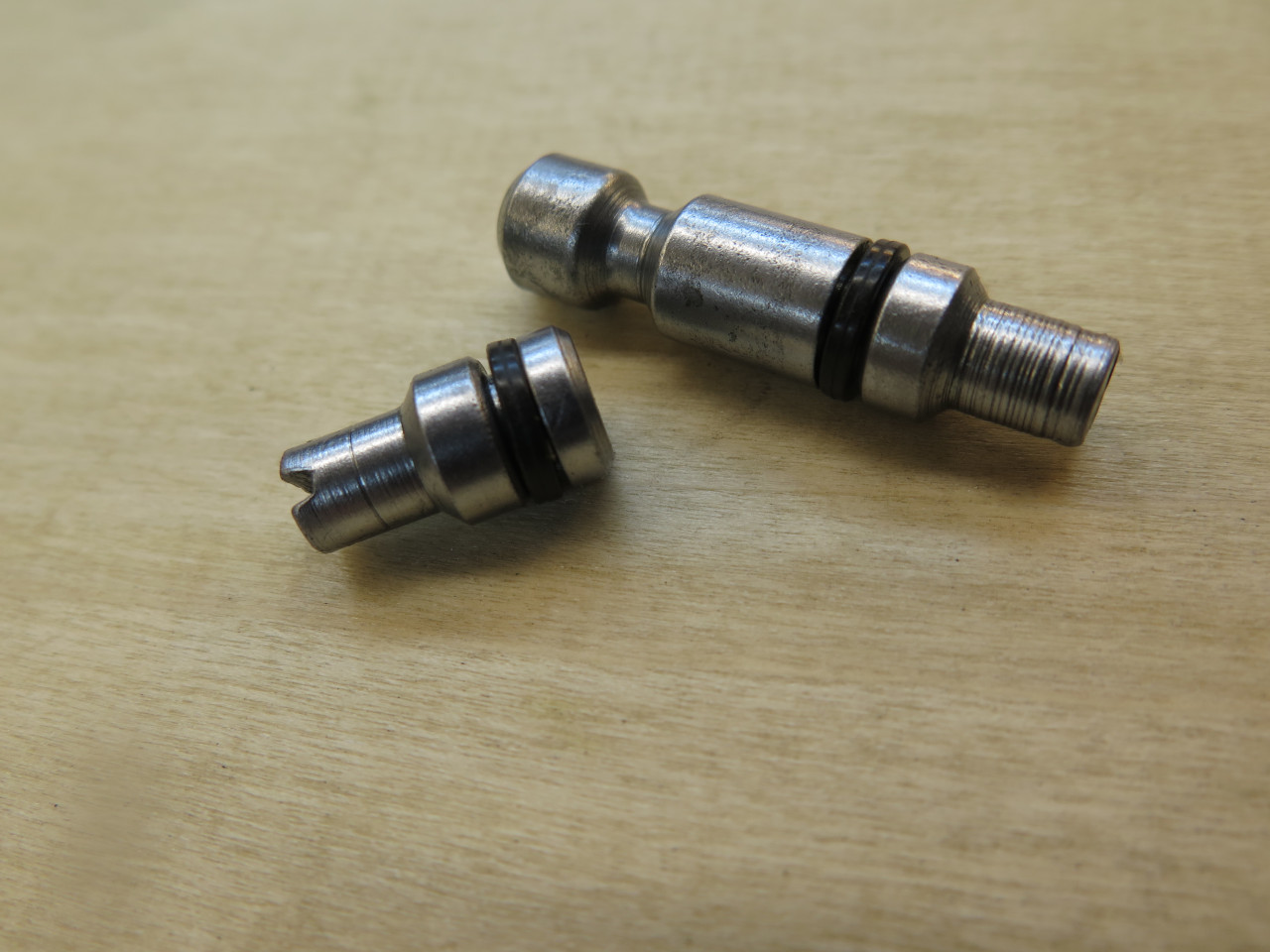
brought it back to life. The little ball bearing is what rides in
the groove in the middle of the two part shuttle. When the
shuttle shifts, it is forced up into a hole in the body and pushes the
snout of the switch.
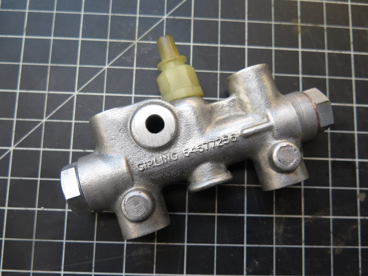
One part of the shuttle is inserted into each end of the body. The
shuttle is in two parts so that neither of the seals have to be pushed
across the switch opening in the bore, which could damage the
seal. Looking down the switch hole, it is obvious when the shuttle
groove is centered. The ball bearing is dropped in, then the
switch installed.
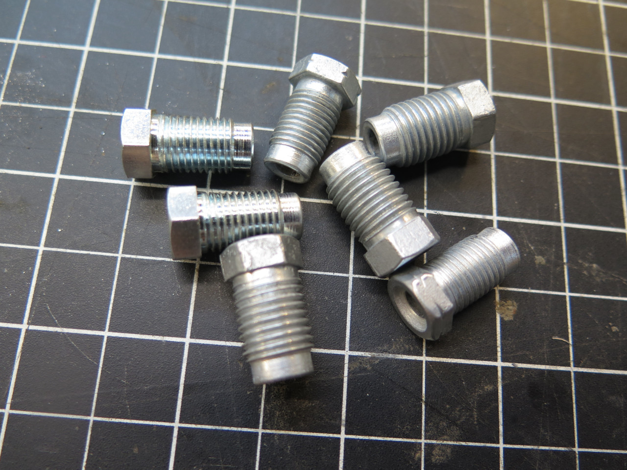
Both the brake master cylinder and the PDWA have two different threads
on their hydraulic ports: 3/8-24 for the rear circuit, and 7/16-20
for the front. This makes it harder for the system to be plumbed
incorrectly. I was able so save most of the fittings from the
original system by stripping and re-plating them. The slightly
shinier fittings are new, the rest are just re-furbed.
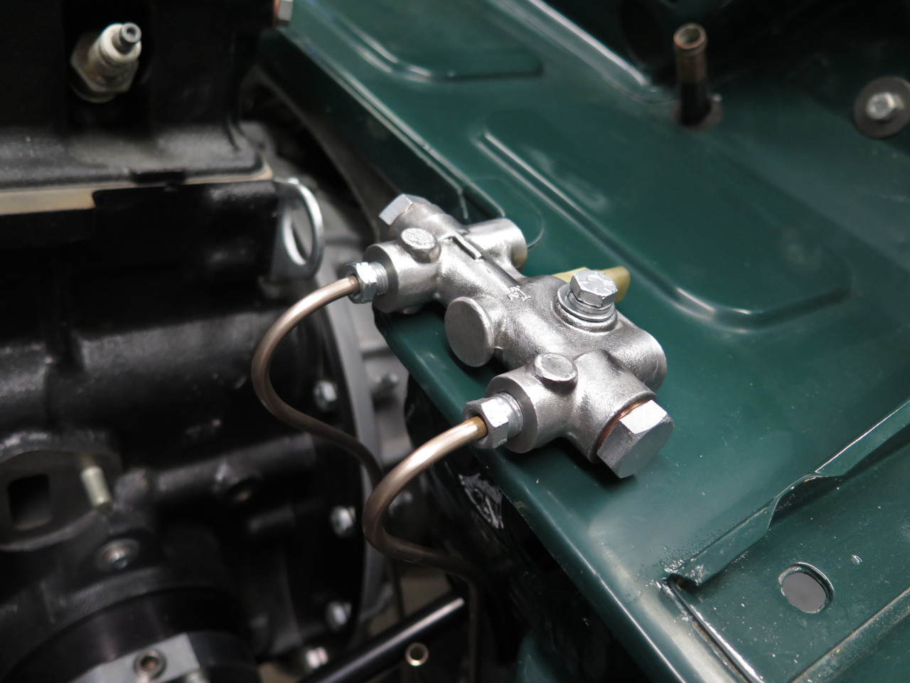
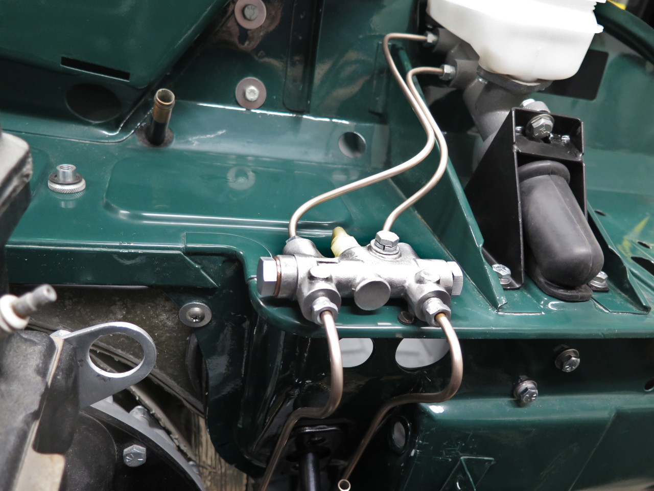
I made new lines to connect the PDWA to the front and rear
circuits. The old lines were a pretty good guide for shape.
To finally button up the braking system, I drug out the master cylinder, along with its assorted bracketry...
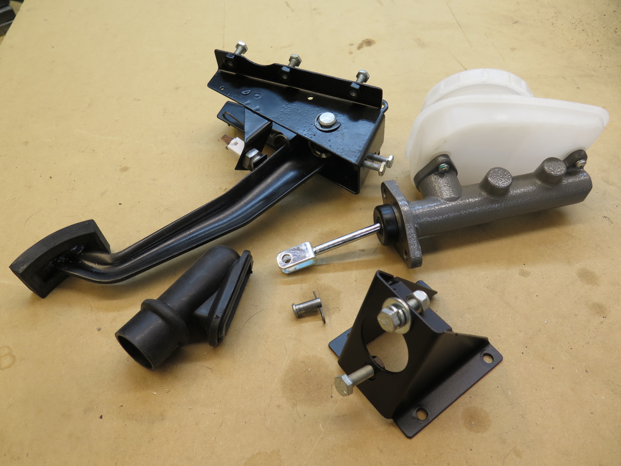
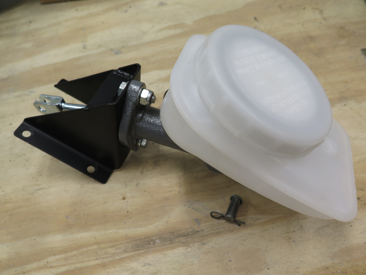
...and got 'er installed with her eight bolts.
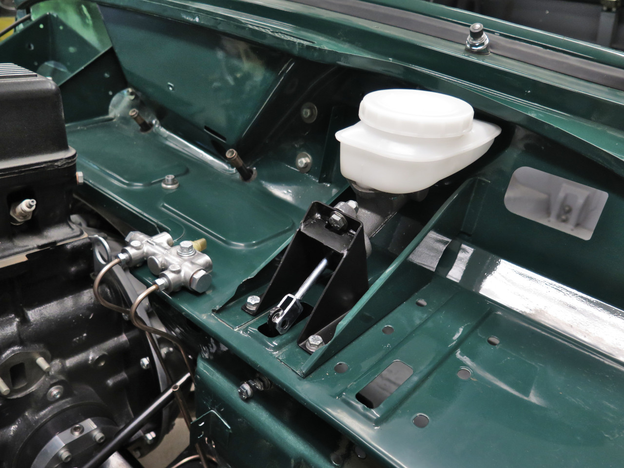
The last two hydraulic lines. These are the originals, which made decent patterns.
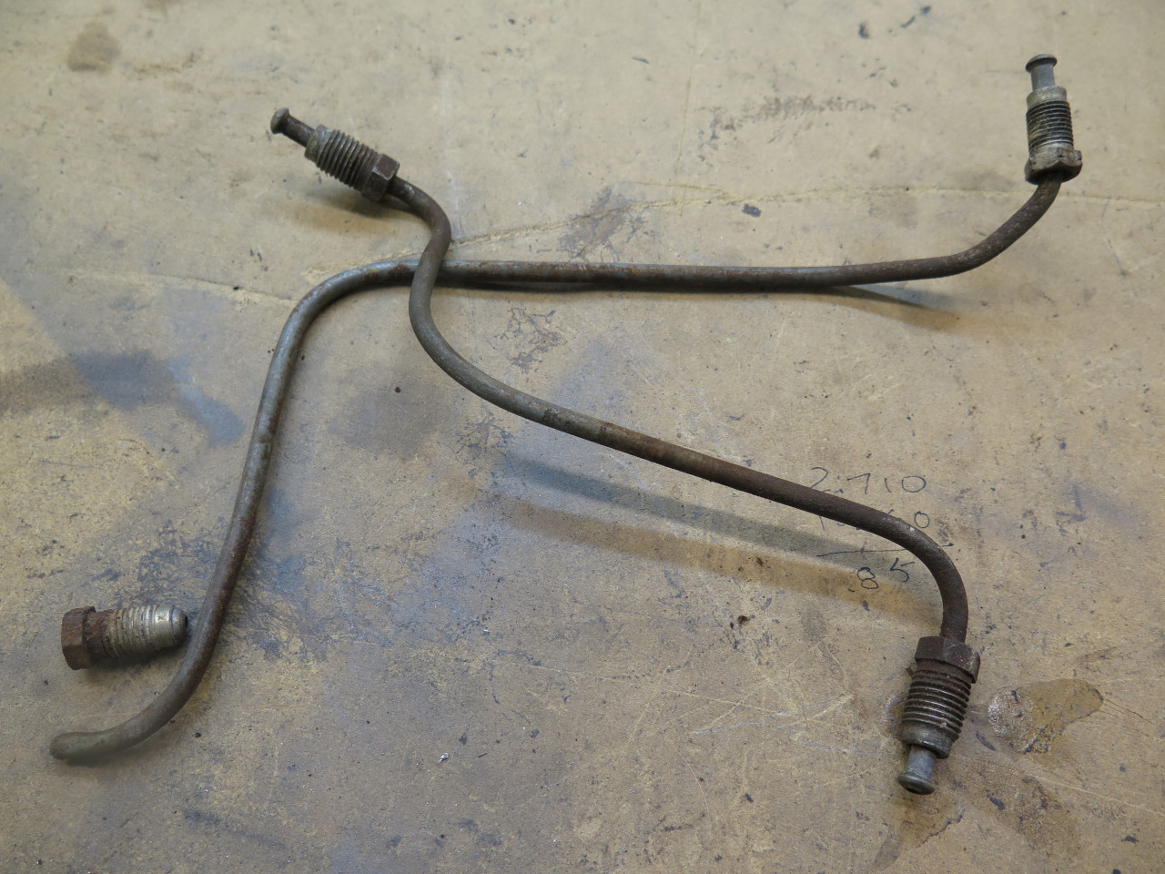
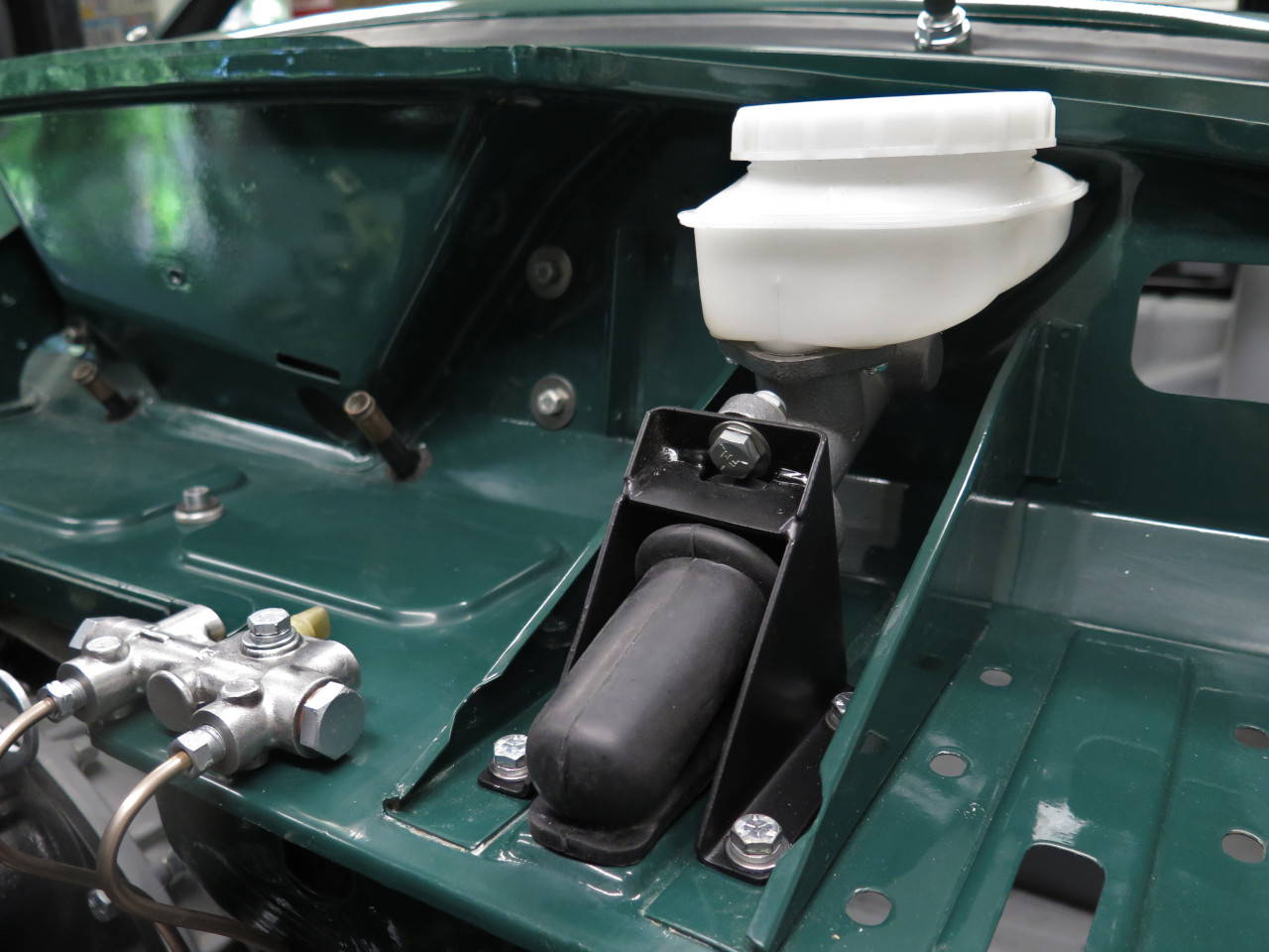
The new replacements. I use a copper-nickel-iron brake line. It doesn't corrode, and is pretty easy to form by hand.
This finishes off the brake system, and it feels good to put a big fat
check mark in that box. Cost for this part was maybe $10 worth of
tubing and a few bucks for the seals and new fittings.
Comments to Ed at elhollin1@yahoo.com
To my other GT6 Pages