To my other GT6 pages
September 1, 2019
Differential
I
once thought that automotive differentials were some kind of black
magic. All of the car manuals I'd seen warned that the exacting
clearances and preloads necessary to rebuild them properly required
special tools and skills. The lengthy list of steps they offered
seemed complex and confusing.
But today, with precicely one apparently successful differential rebuild
under my belt, I am a little less aprehensive. Still, tearing
into a differential that I really want to be spot on is not something I
take lightly. It takes a lot of focus and concentration to keep
from making stupid mistakes.
As
far as I knew, the diff in the car was working OK when the car was
parked 30 some years ago. So my approach was to go slow, and to
try not to fix something that didn't need fixing.
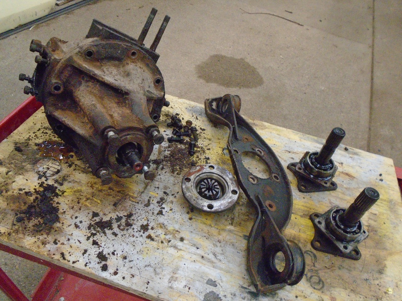
The
first thing I noticed when I hauled the 50-some pound lump up onto the
work table, was that the pinion seemed very free-turning. Pinions
normally turn in pre-loaded bearings that cause the rotation to be
noticeably stiff. The backlash also seemed to be a little
generous. I decided to open her up.
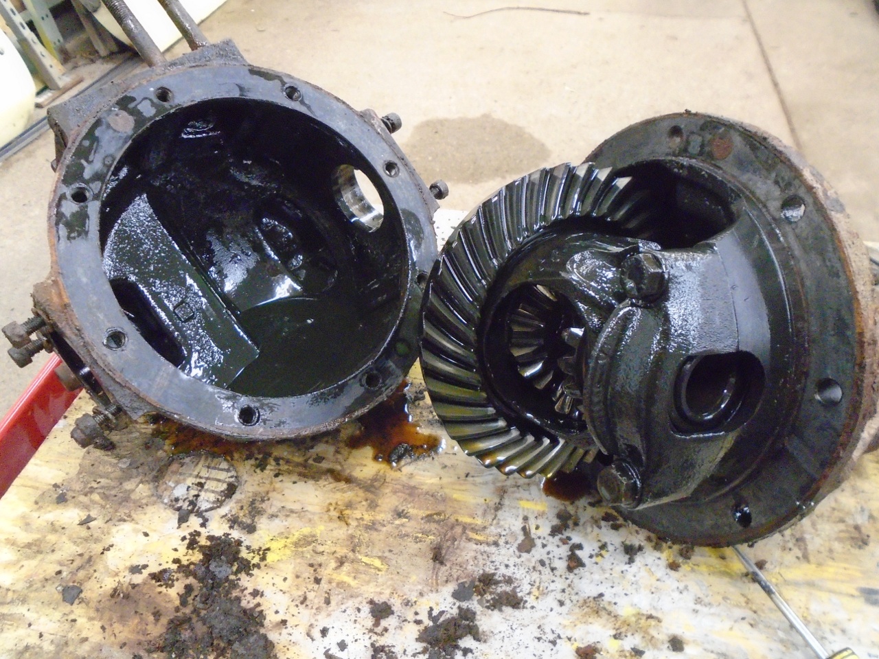
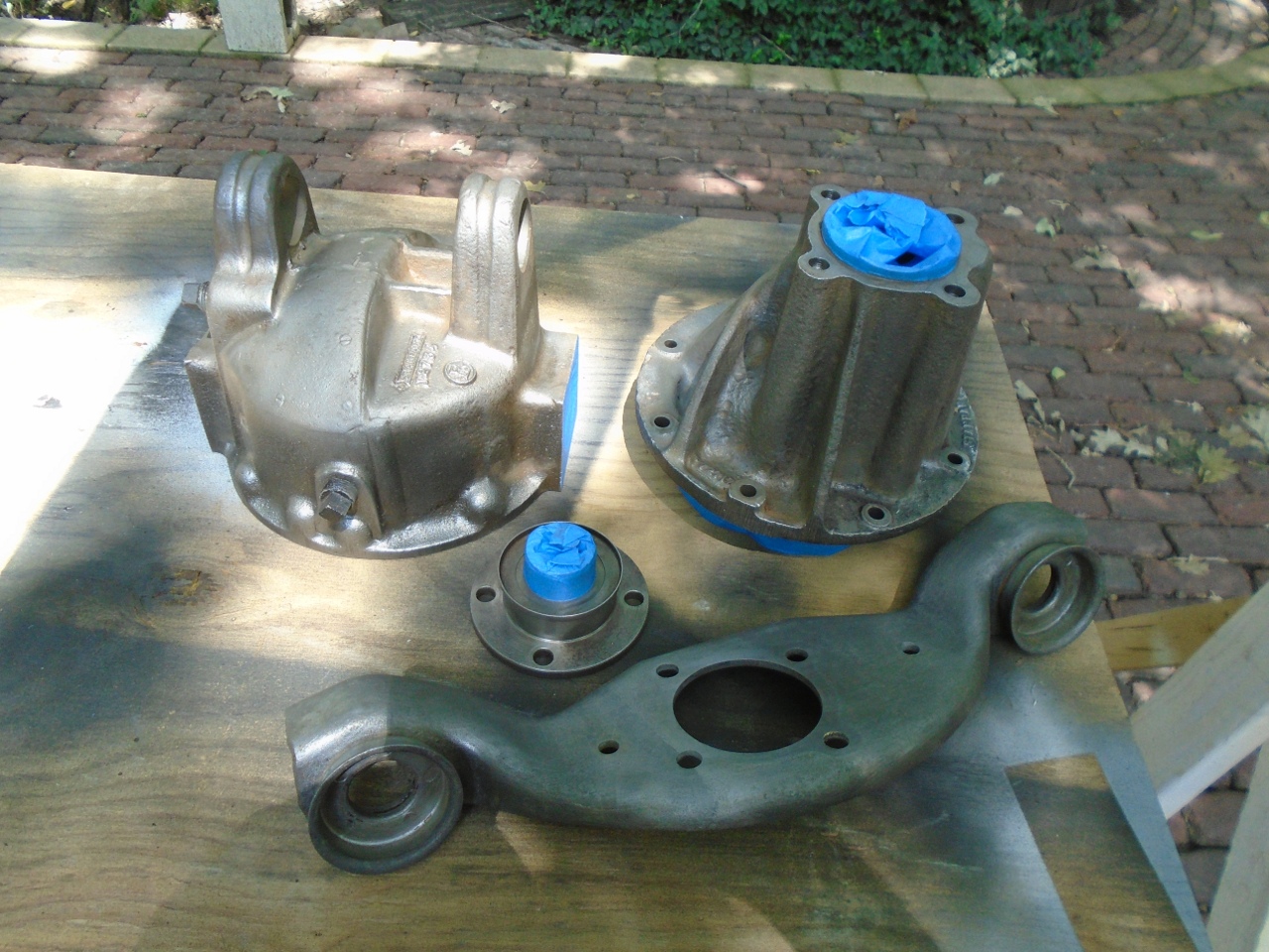
Since
I had everything out of the cases, it was a good time to clean and
paint them. Sand blasting is a really good way to get rid of
paint and rust. Blasting goes better if the parts are degreased
first. I tried to plug all entries to the inside to minimize the grit on the interior.
Blasting didn't take long.
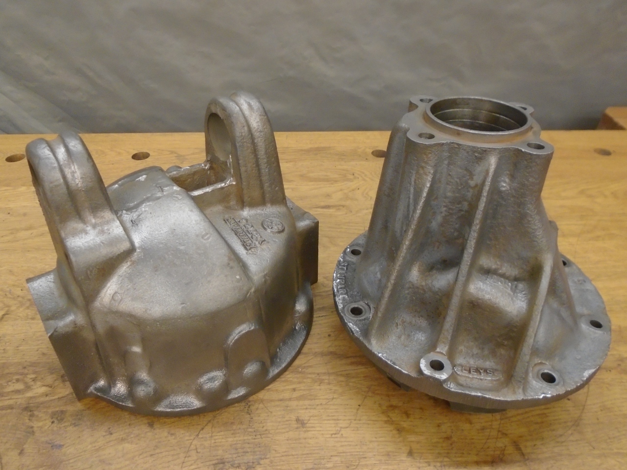
Having bare cases also presents an excellent opportunity to do a couple of small mods.
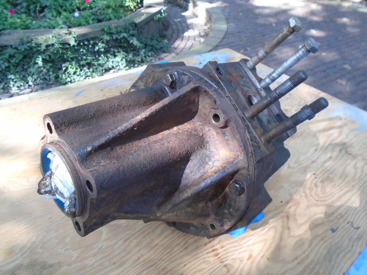
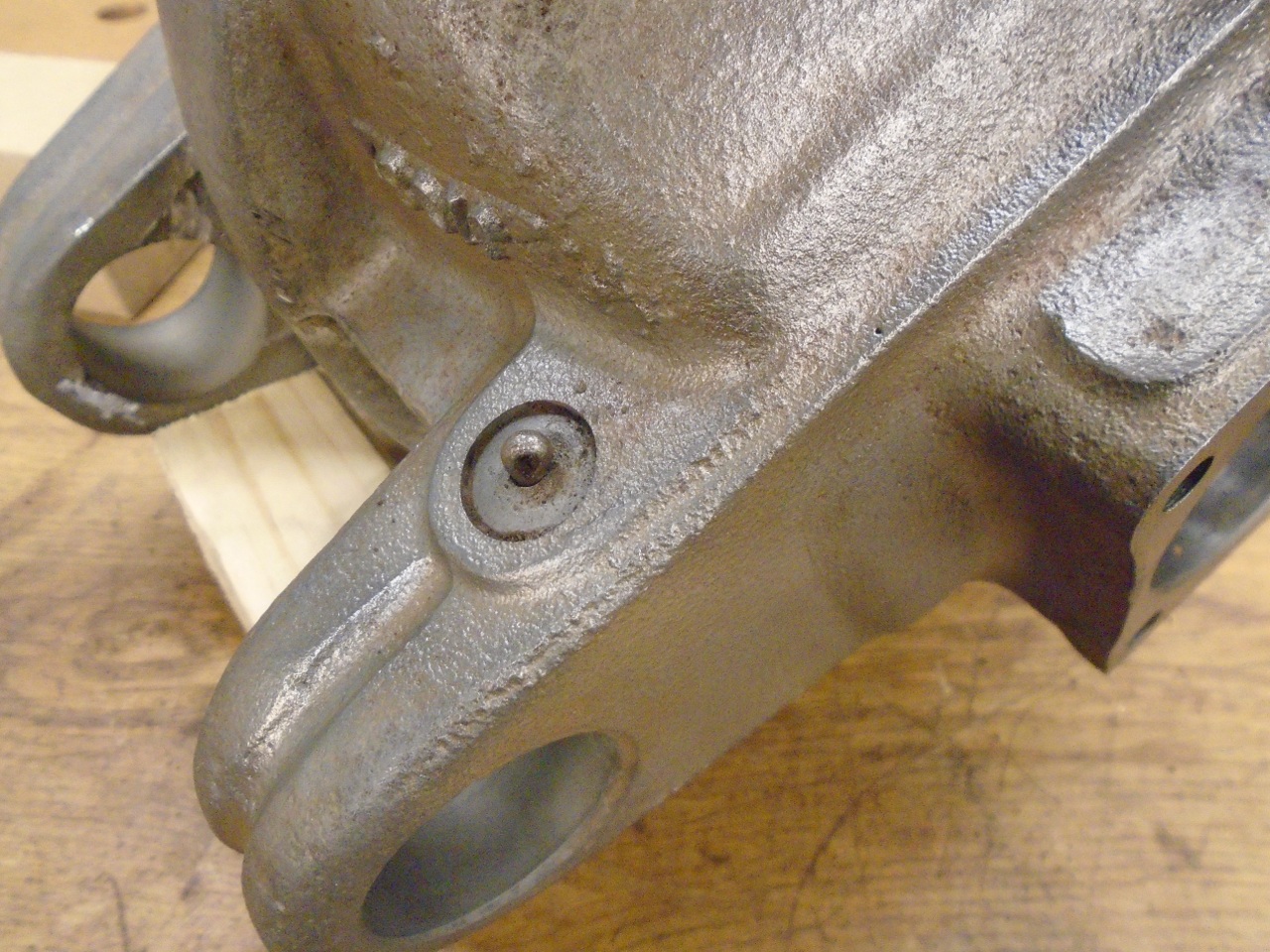
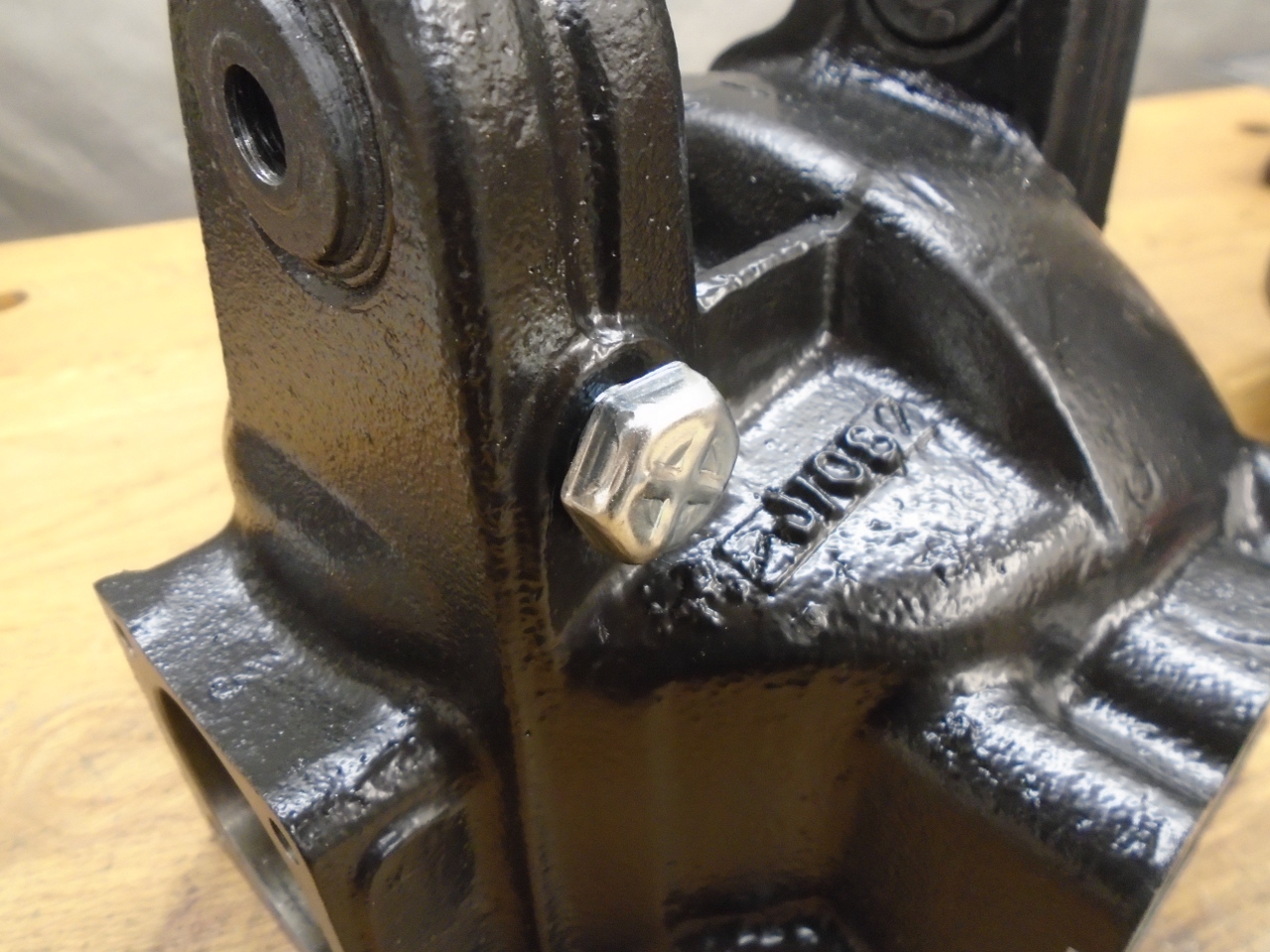
This
is the vent for the differential. Differentials get hot when they
operate, and the rise in temperature raises the air pressure in a
sealed case. Higher pressures foster leaks. The vent is just a
small hole to let air pressure equalize. As is pretty common with
simple vents of this type, the hole had a loose cotter pin in it.
The pin is presumably there to rattle around and prevent the hole
from becoming clogged with road grime. This often didn't work.
There
are better vents. This one, made especially for differentials and
transmissions, features a cap to keep crud from falling into the vent.
It also has an internal filter material.
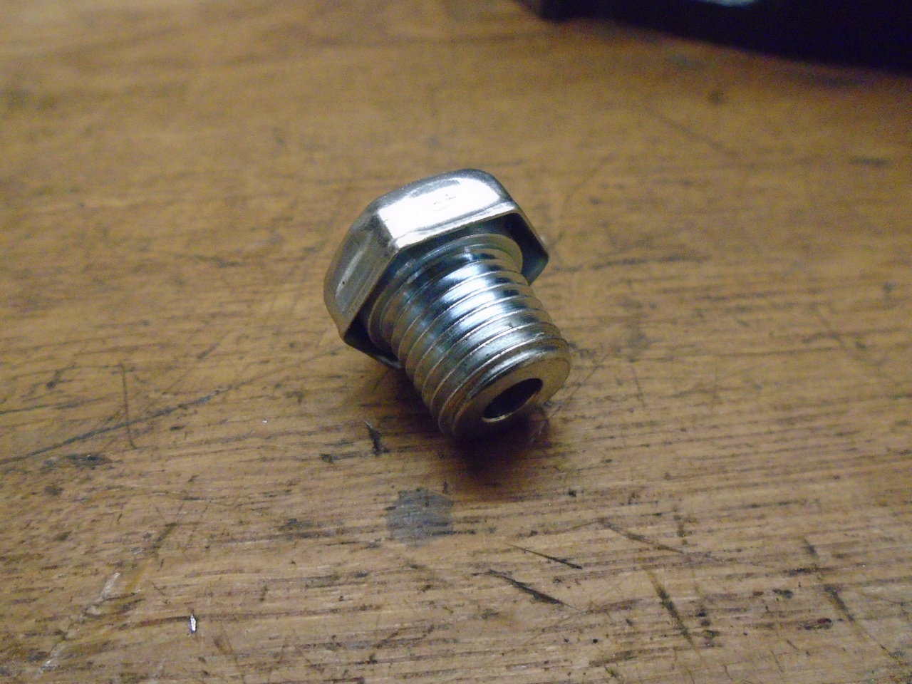
The new vent takes a 1/4 NPT thread.
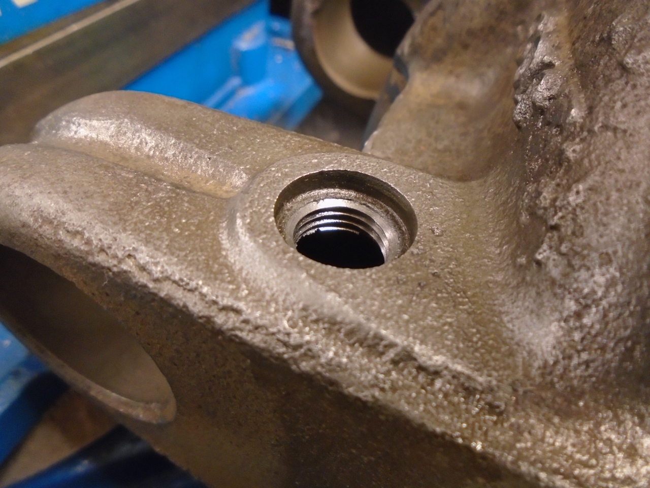
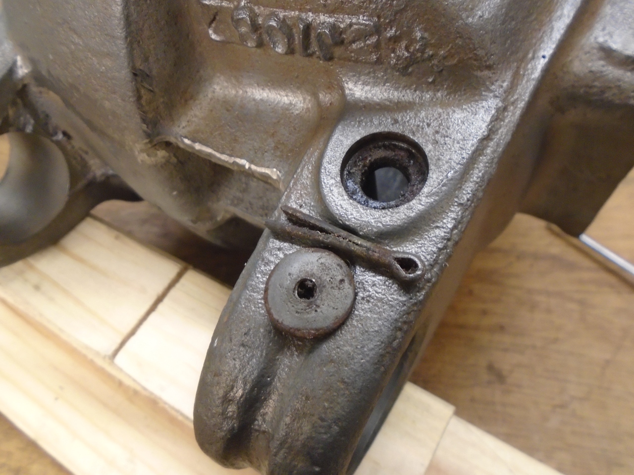
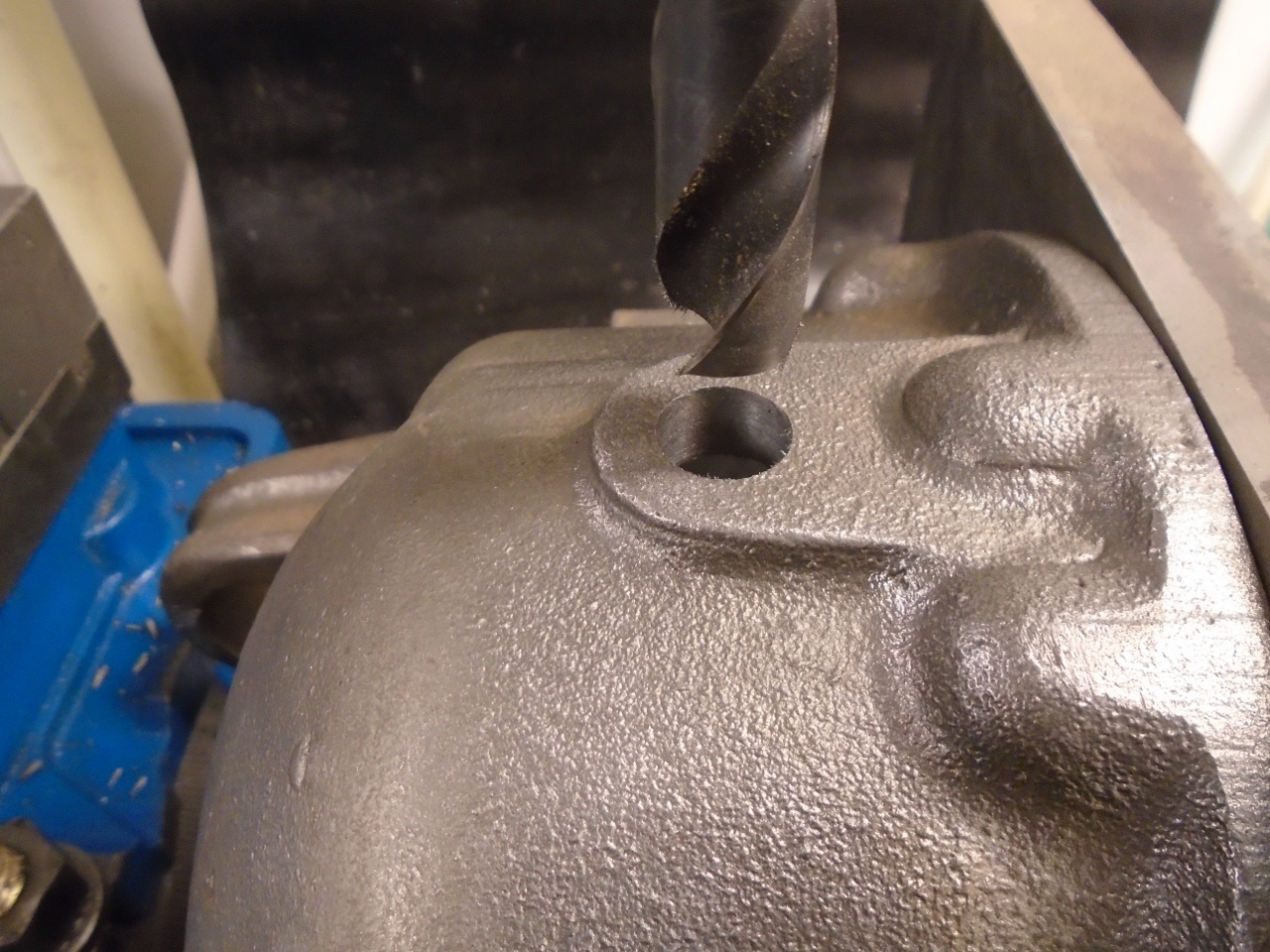
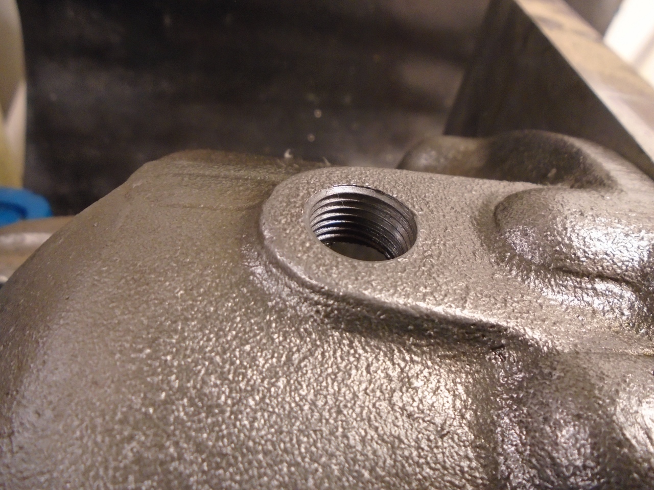
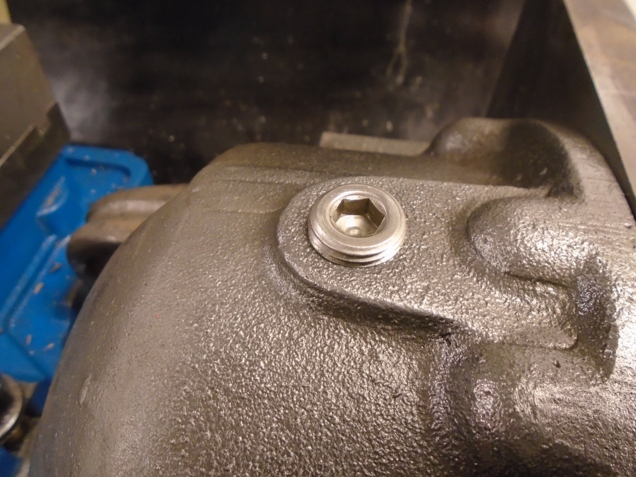
While
in a drilling and threading mood, I decided to also do another mod that
is pretty common. This is the bottom of the rear case half.
There is a boss there at the lowest point that was clearly
intended for a drain port that was never installed. Drill and tap
for 3/8 NPT, and we have a differential drain.
With the cases cleaned and modded, it was time to paint. A nice 2-part epoxy primer and topcoat should be pretty durable.
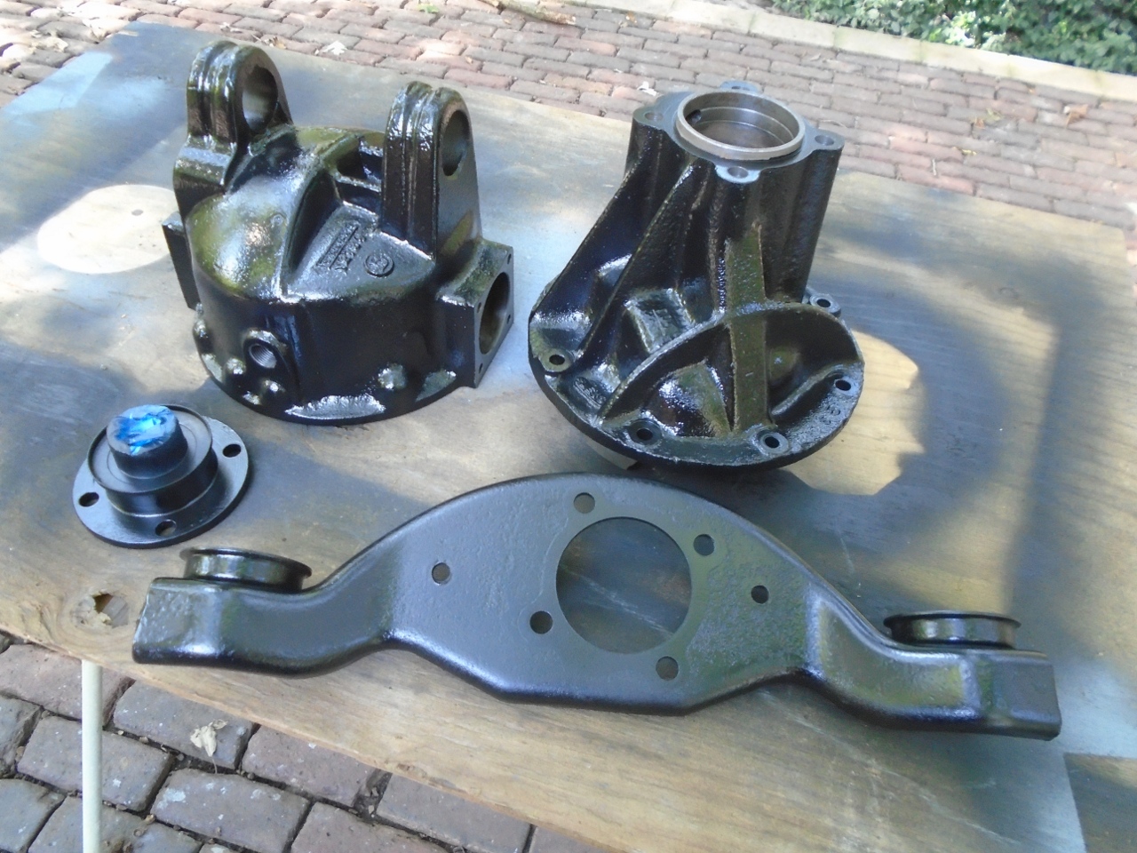
New rear bushes and pop in the vent.
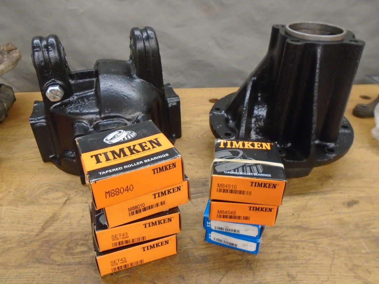
By
this time, I'd decided to try to re-set the backlash and pinion
preload. I thought it would be silly to dig that deep into the
diff without installing new bearings. This, of course, ups the cost of the refurb quite a bit.
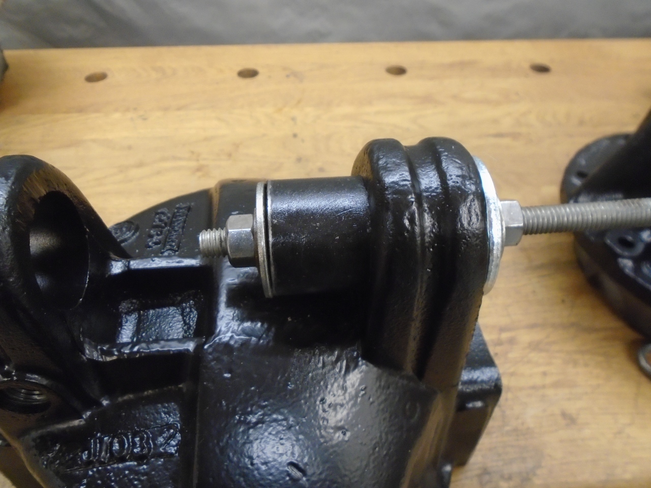
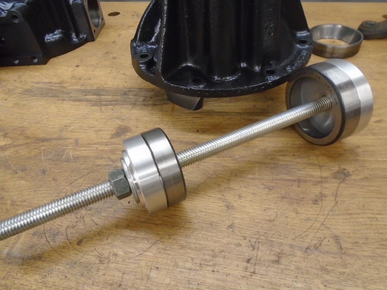
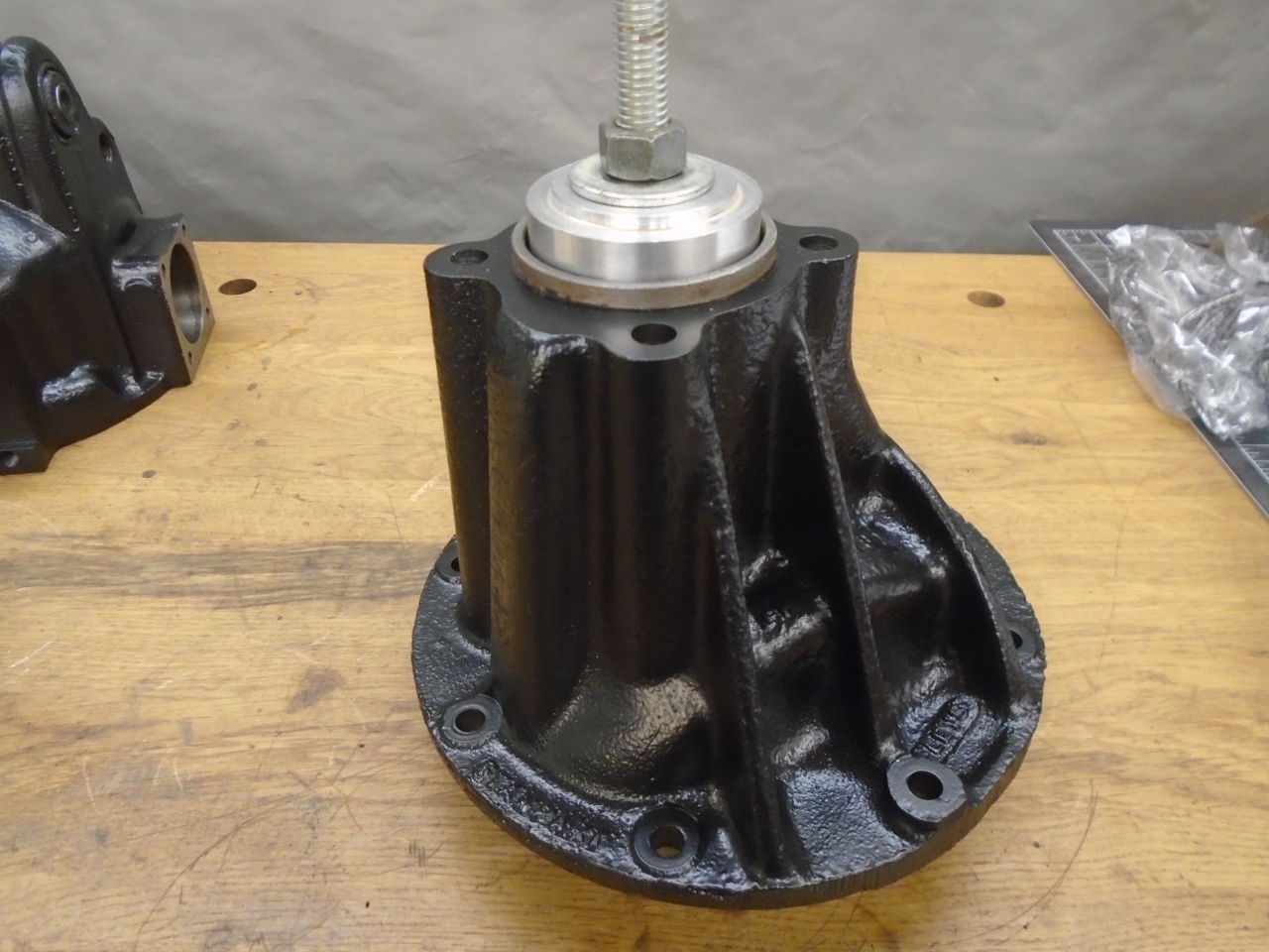
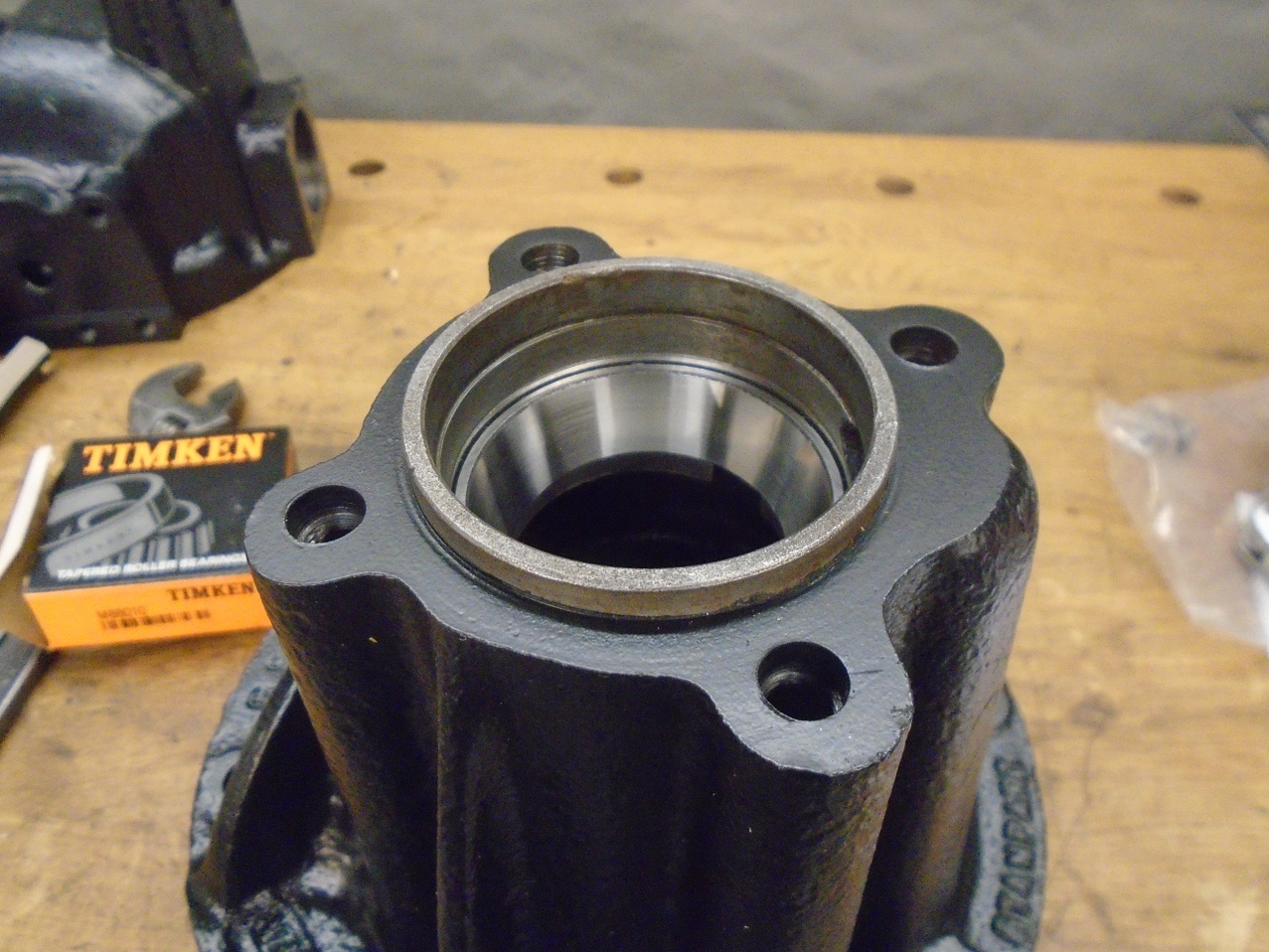
After
removing the old bearing cups and doing a thorough cleaning of the
inside of the cases, the new bearing cups for the pinion shaft have to
go to their forever home. The threaded rod gizmo pulls both cups
into place at the same time.
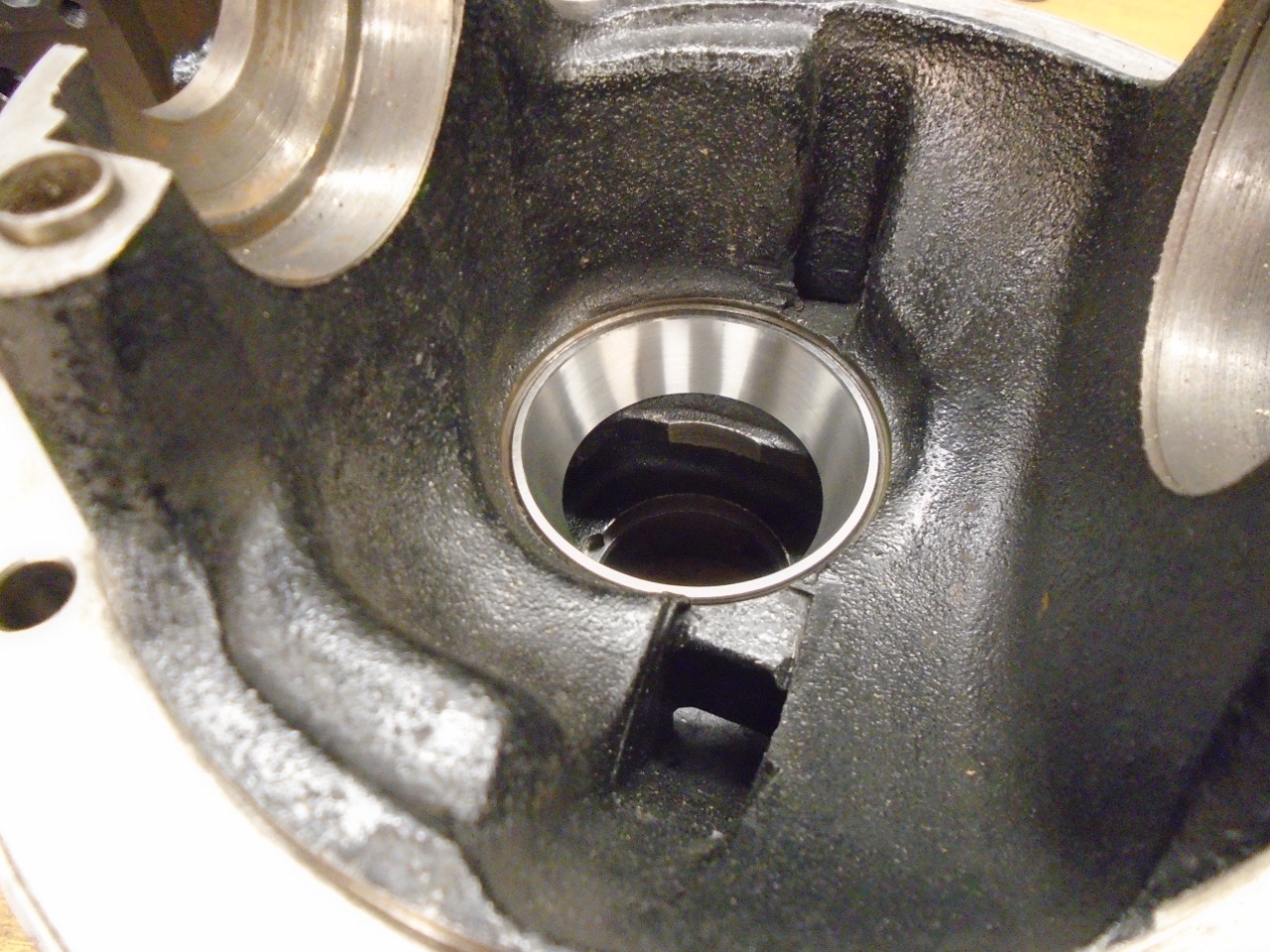
The
first ctitical setting in this diff was the pinion height. The
pinion has to be in a certian fore-aft position relative to the crown
gear to ensure proper mesh of the teeth. There was apparently a
factory tool to help set pinion height, but they would be like hen's
teeth today. I believe it worked by measuring from the top of the
pinion head to the flat surfaces where the differential carrier caps
seat. It was complicated by the fact that pinion heads apparently
varied a little in thichness, and in fact each factory pinion came with
a marking indicating how much it differed from some set standard.
I
took a slightly different tack. There is a specification in the
factory manual for the "Distance from head bearing abutment face
on pinion to center of crown wheel bearings". I took this to mean
the distance from the backside of the pinion head (where it meets the
pinion shaft) to the flat surface where the differential carrier caps
seat. To check my interpretation, I set the rear pinion bearing
cone in the cup, and added the original 0.081" shim. The top of
that shim is where the pinion's "abutment face" rests. Measuring
this distance, I came up with something within less than 0.002" of the
manual spec (which is 3.03125").
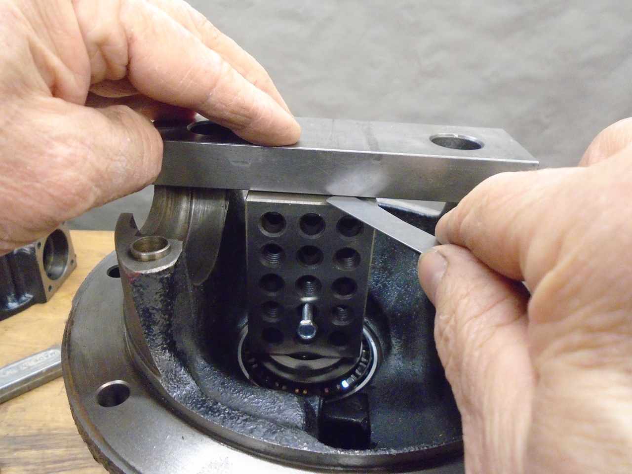
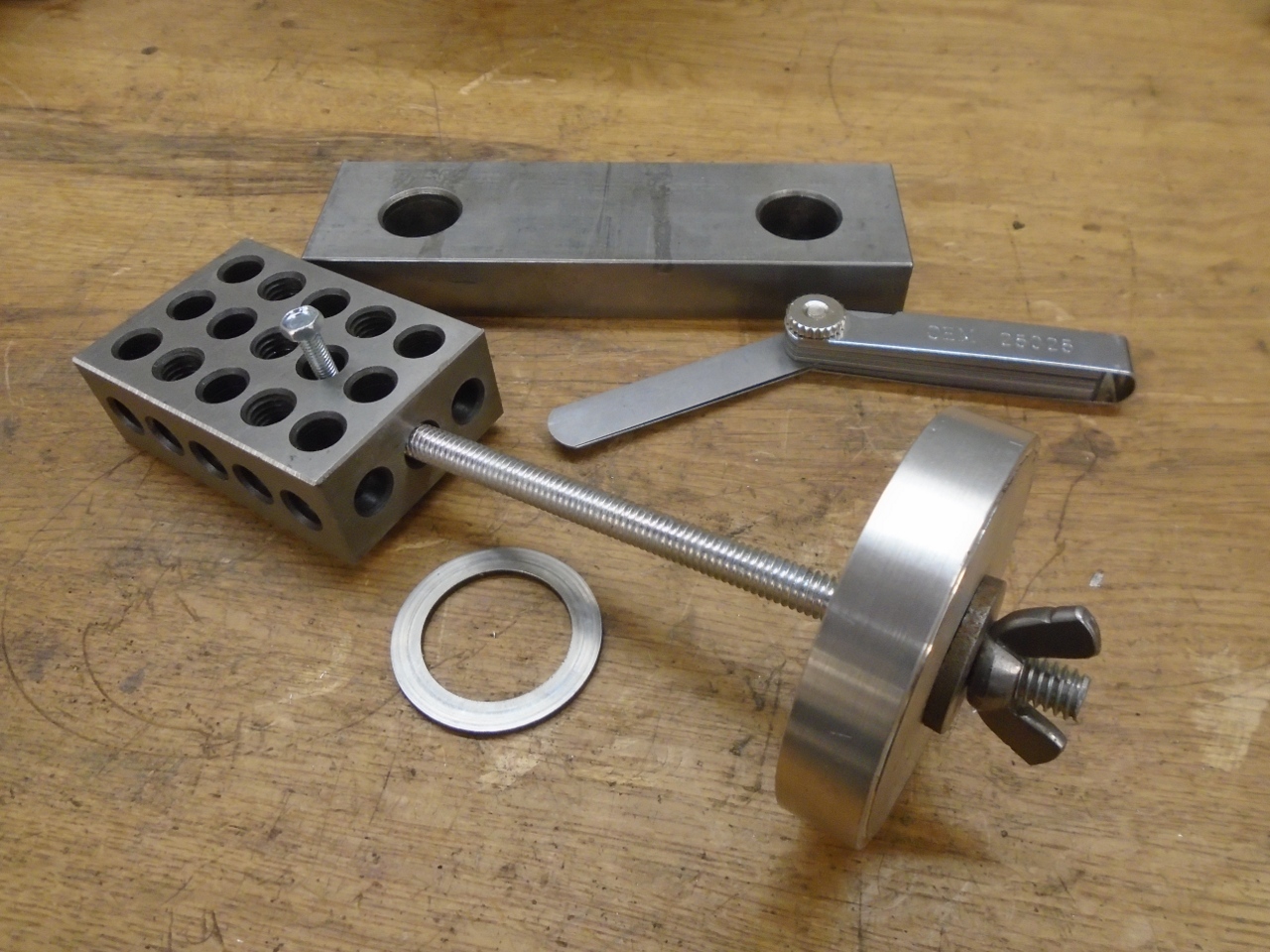
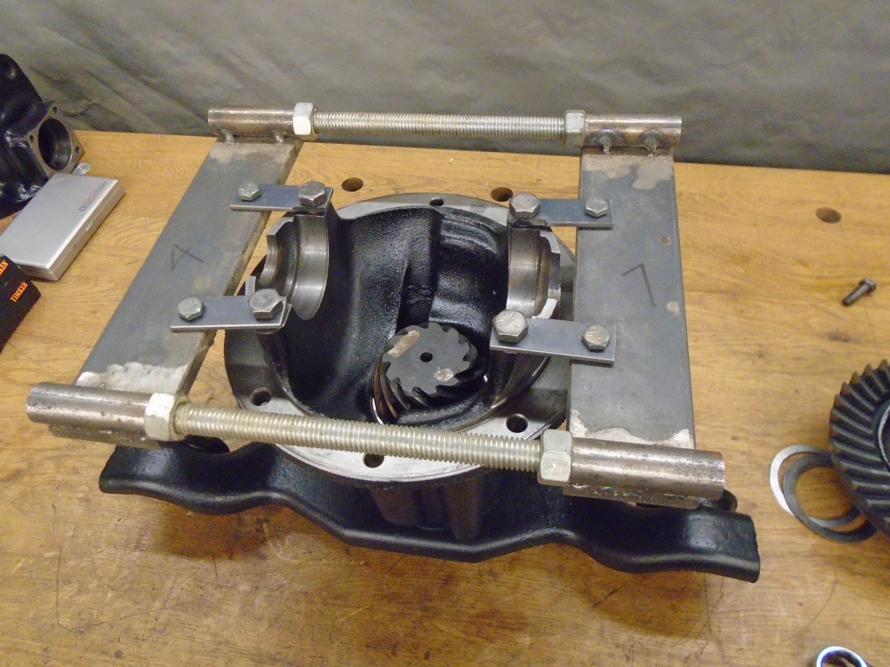
This
was my setup for the measurement. on top of the 0.081" shim is a
presicion machinist's block that is 3.000" tall. Across the flats
at the center of the crown wheel bearings is a precision ground
parallel that has very good flatness. By the spec, there should
be 0.03125" between the top of the block and the underside of the
parallel. With feeler gauges, I measured 0.033. The pic on the
right shows how I managed to hold the block rigidly in place for
the measurement. This would also emulate the preload on the bearing.
The
pinion height is adjusted by the shim under the pinion head.
Thicker shims will raise the pinion, and my pinion needed to go
up a little less than 0.002". The next larger shim that I could
find was 0.084", so I ordered one of those, plus a new 0.081" shim.
It turned out that the new 0.081 shim got me closer to the spec.
It appeared that the original 081 shim was slightly worn.
At
that point, with pinion height set, I moved on to set the pinion
bearing pre-load. Correct preload is gained by precisely setting
the distance between the front and rear pinion bearing cones.
This is done with a steel distance piece and thin shims.
When the pinion nut is tightened to its spec torque (90-100
ft-lb), the bearings are under a load determined by the spacing.
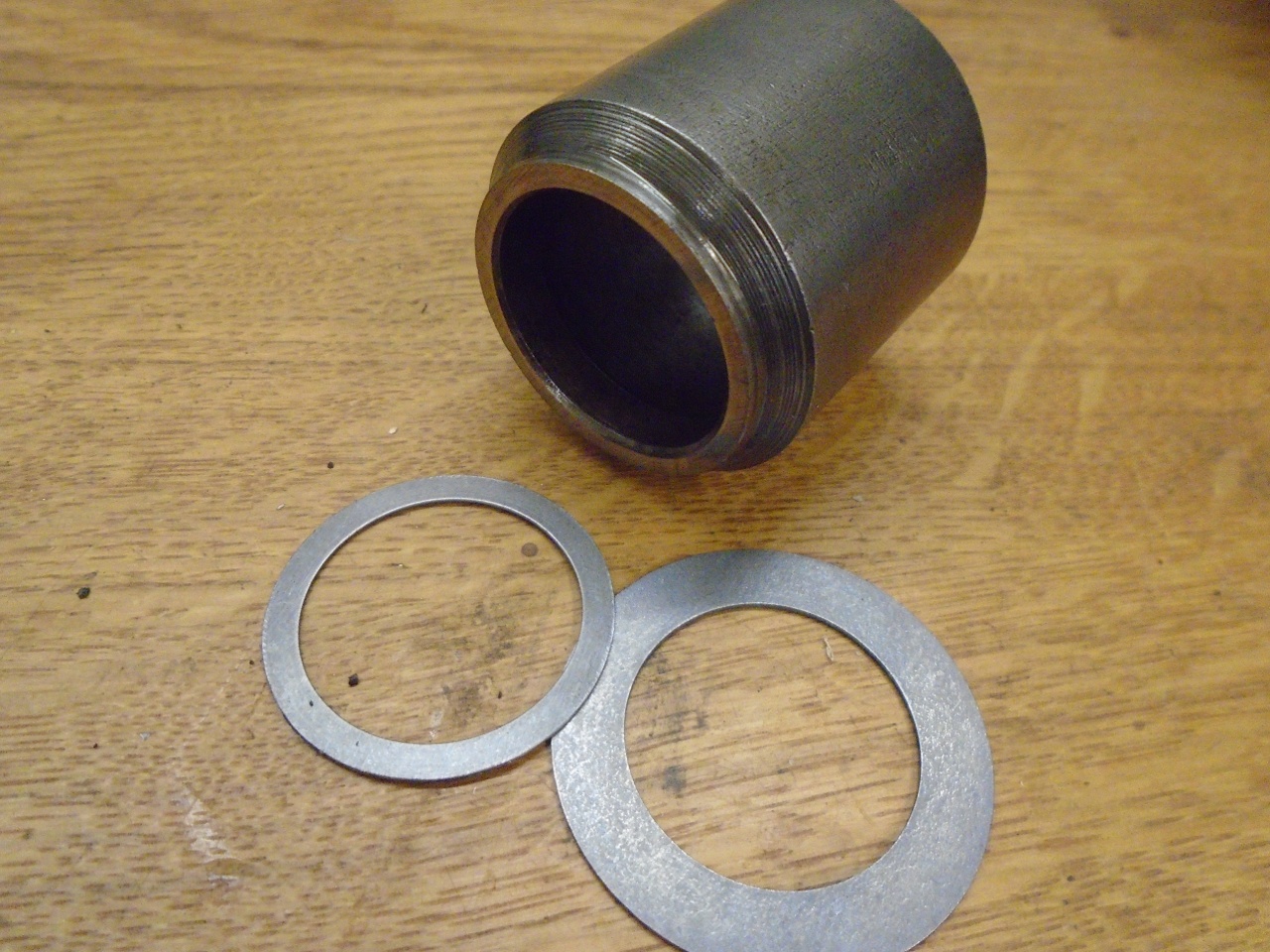
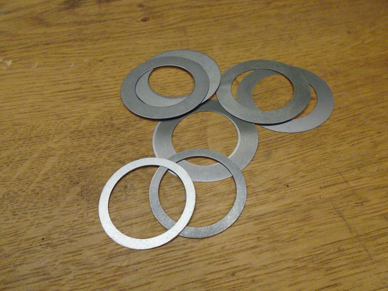
I
couldn't immediately find the proper shims (1" ID, 1-1/4" OD), but I
found an assorted set of shims with 1" ID and 1-1/2" OD. Luckily,
ODs are easier to trim than IDs.
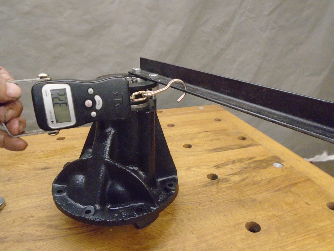
Preload
is measured by the torque it takes to turn the pinion. I think it
took three iterations or so to get something in the 12-16 inch-pounds
window. Since the pulling point on my setup was actually four
inches from the axis, the reading on the scale had to be multiplied by
four to get the actual torque.
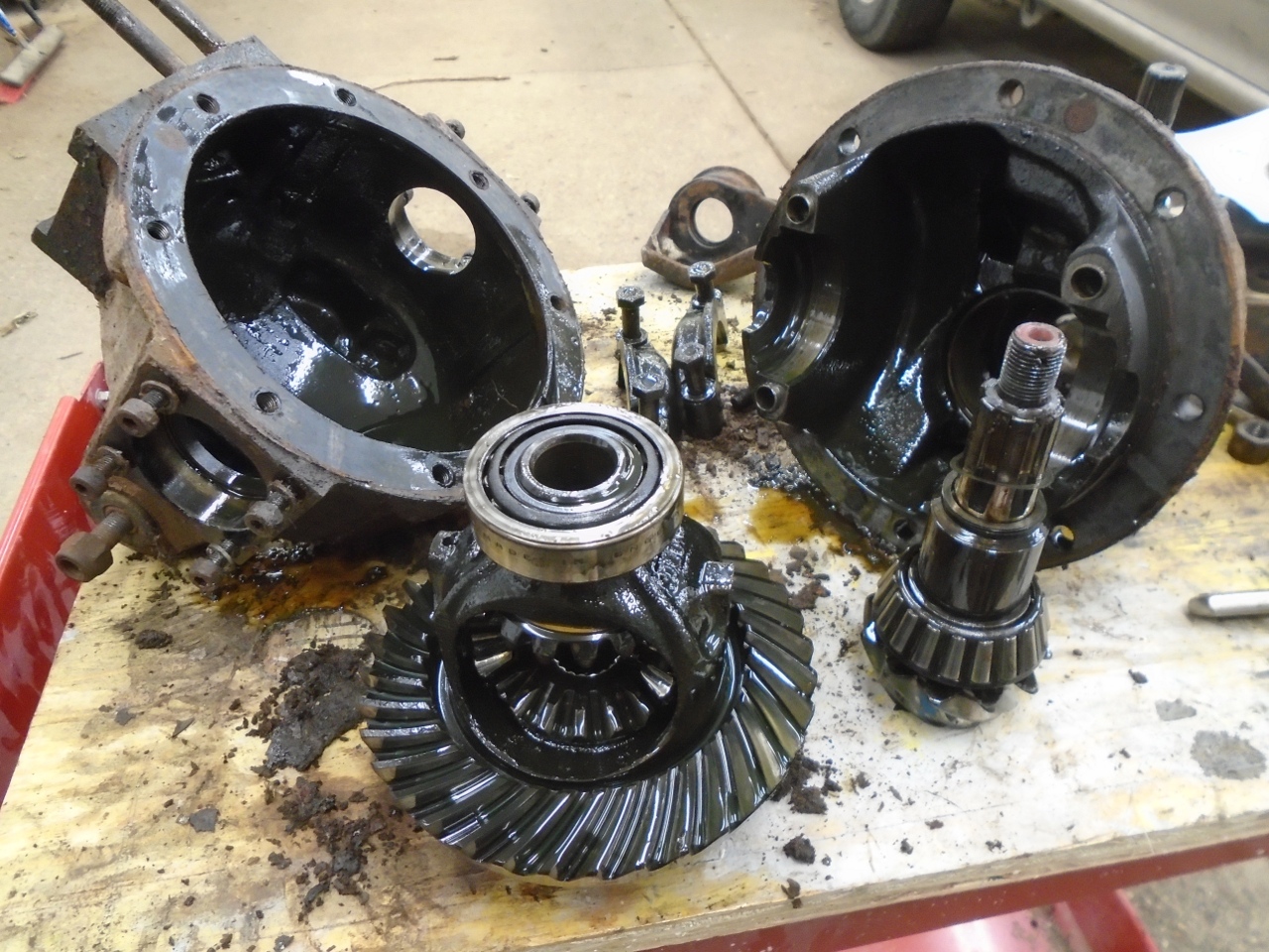
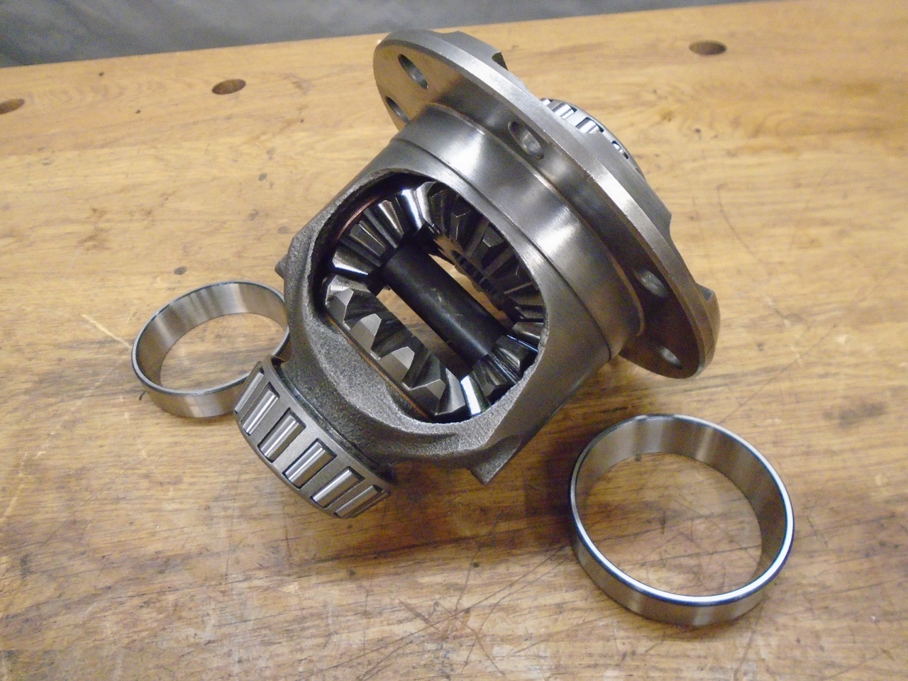
With
the pinion in good shape, I turned to the differential carrier.
This assembly's job is to allow the wheels of the car to turn at
different speeds while both are driven buy the engine. It
consists of two "sun" gears connected to the wheel axles, and two
"planet" gears that act as idlers between the sun gears. Ideally,
the backlash within the sun/planet gearset should be as small as
possible, consistent with free movement.
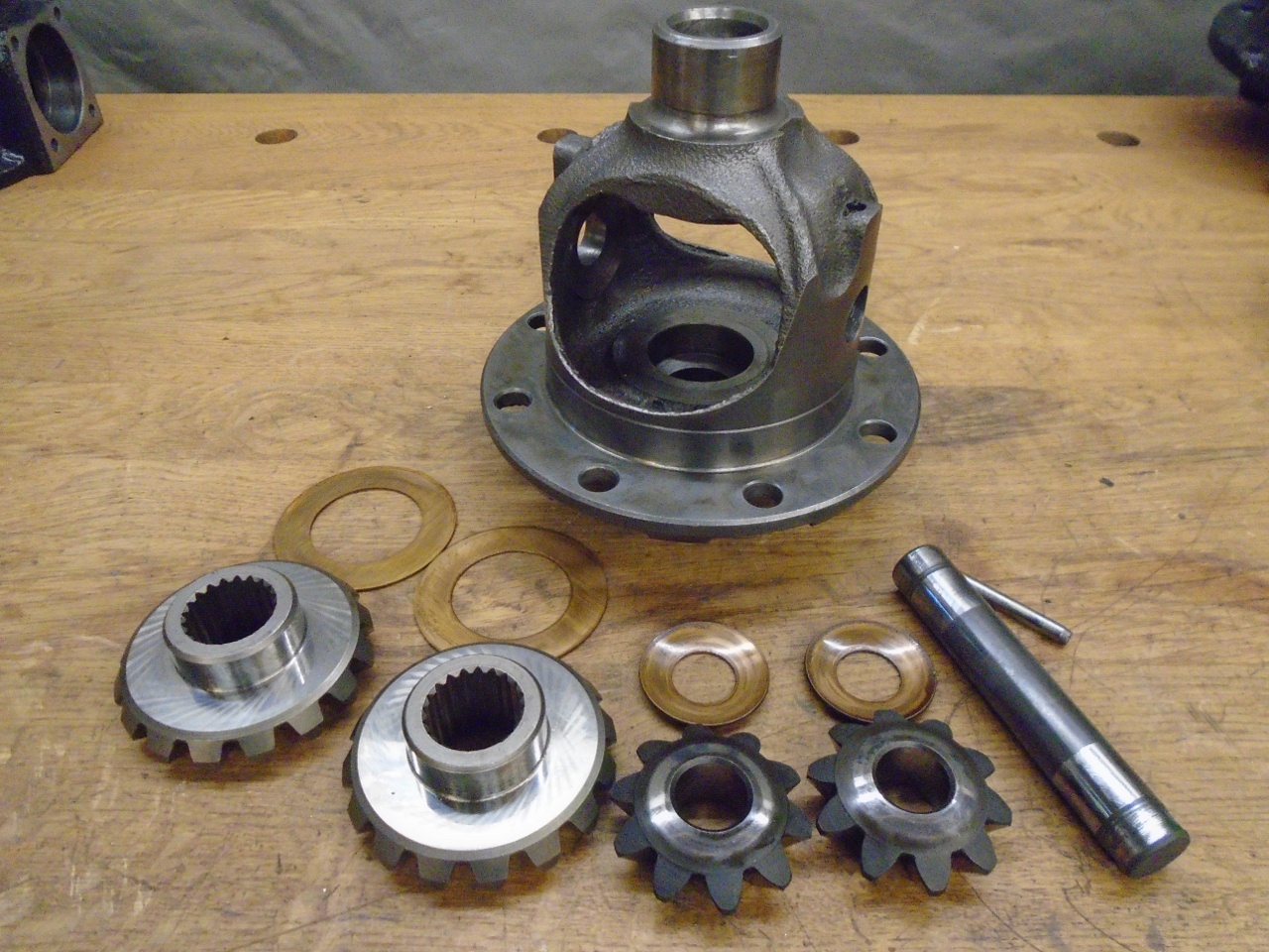
My backlash was about 0.010", so it needed some work.
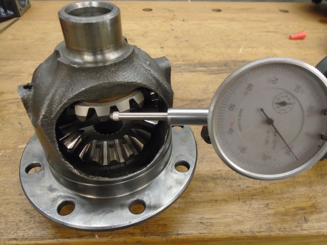
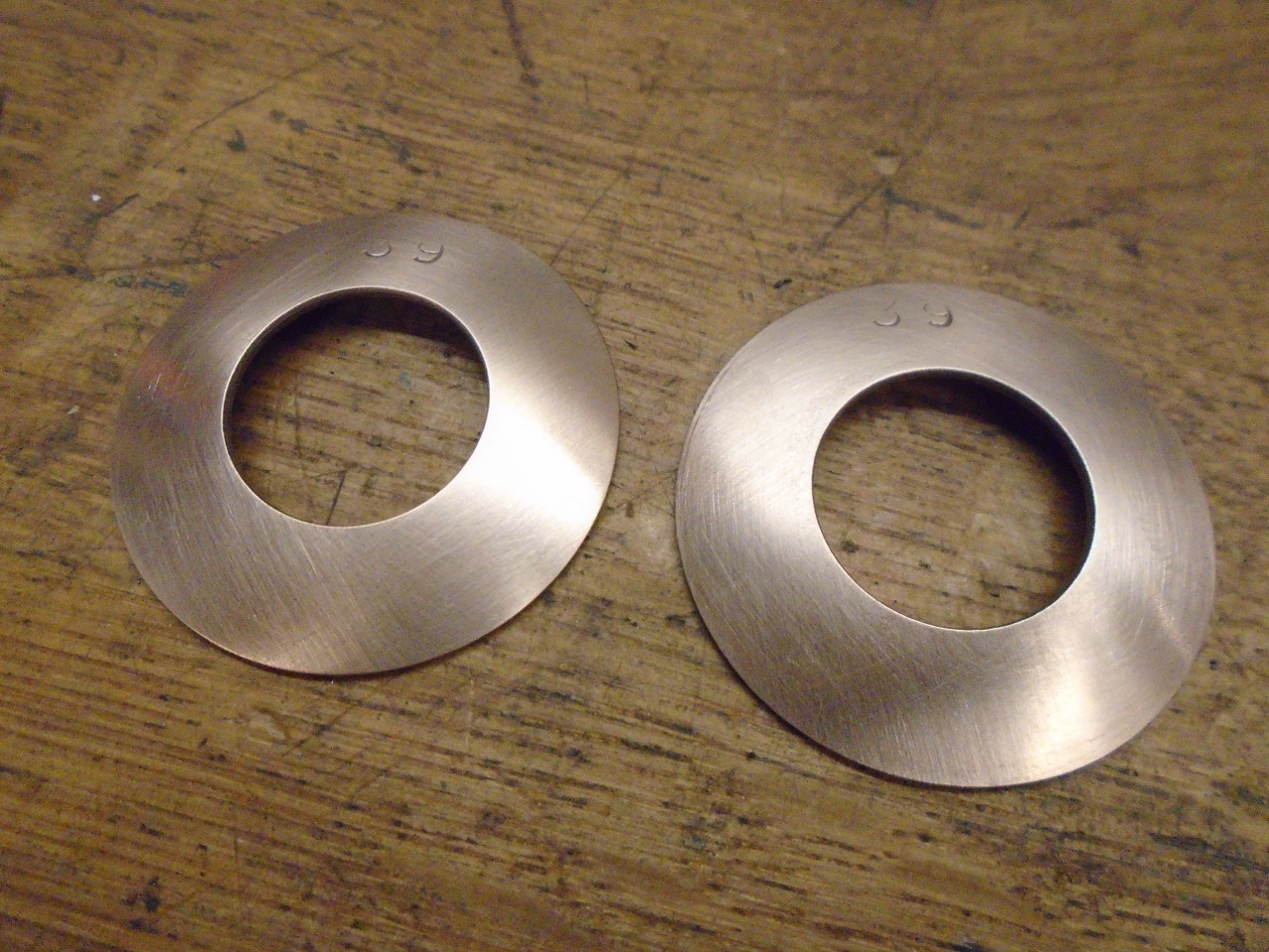
Backlash
is set by varying the thickness of the spherical copper washers behind
the planet gears. Unfortunately, no one I could find supplies the
washers. It was frustrating to realize that wahsers for the TR6
are widely available, and are the same ID and OD, but are quite a bit
thicker. I read online about one ingenious fellow who made
washers from sheet copper by clamping them between a planet gear and
the housing. I looked at this, but didn't have any copper of the
right thickness.
My
final solution to this was to electroplate new copper onto the original
washers. I worked out a current density and time that would plate
about 0.001" of new copper all around (washer thickness increased by
about 0.002"). After each plating session, I assembled the
carrier and measured the backlash. It took four cycles to get to
the point where backlash was very close to zero, but the mechanism
still turned pretty freely.
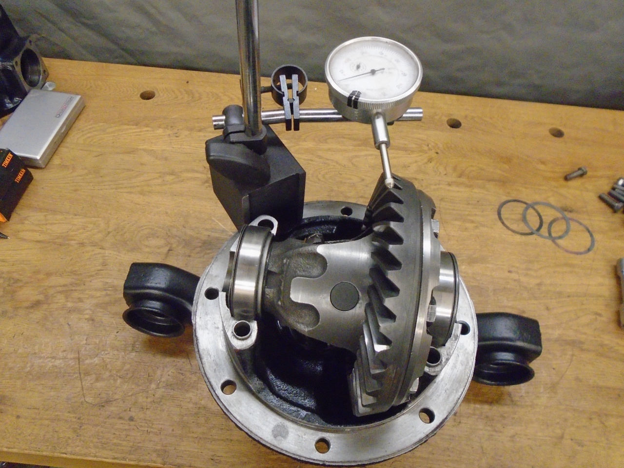
The
next step was to set the pinion-crown wheel clearance. This is
done by moving the position of the crownwheel left or right by shims
placed between the differential carrier bearings and the case.
The total amount of shim is determined by assembling the carrier
into the case without the crownwheel and measuring the distance it can
float from side to side. The total shim pack is set to this
distance plus 0.005". The extra 0.005" places a pre-load on the
bearings. This total shim pack is divided into two parts, with
one part going behind the bearings on either side of the case.
The crownwheel position is set by moving individual shims from
one side to the other. Compared to the shims I found in the diff,
I had to add 0.003" to the total shim pack, and move 0.008" from the
off side to the crownwheel side. I also could not find much
variety of these shims to purchase, so they were mostly home-made.
A case spreader allegedly makes installing the carrier with its shim packs easier.
As a sanity check of proper shim distribution, the backlash between crown and pinion should be between 0.004" and 0.006".
The
final determination of proper setup is the contact pattern on the crown
teeth. This is seen by coating some of the teeth with a dye, and
meshing them repeatedly. The contact areas will wear the dye
away--eventually.
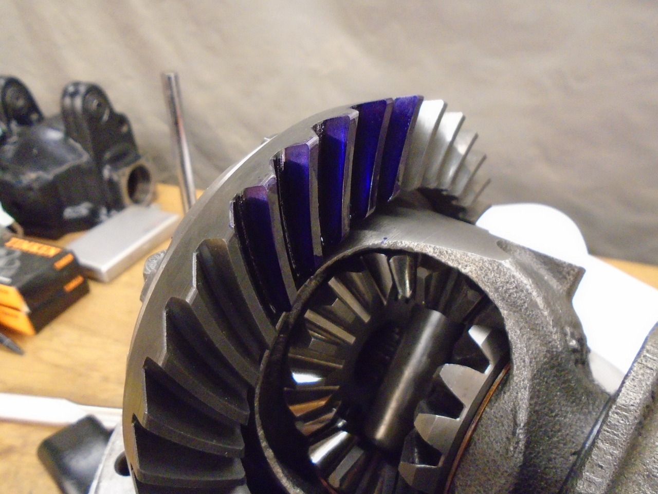
With
no load on the teeth, the contact patches are very slow to appear.
I could begin to see them about the time my arm got tired of
moving the pinion back and forth, but the camera still couldn't capture
them. They looked very close to the desired pattern in the shop manual.
At last, I could button her up.
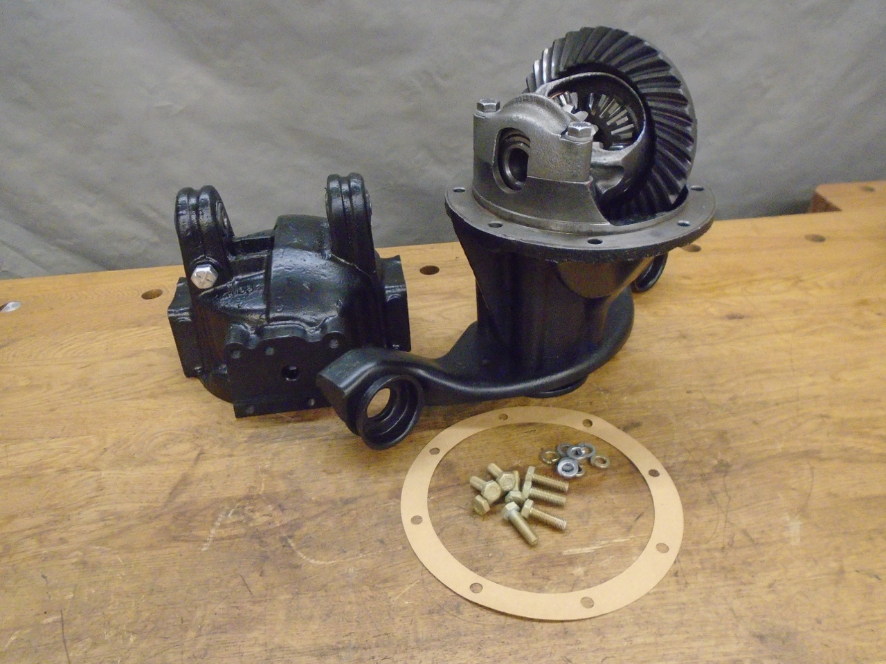
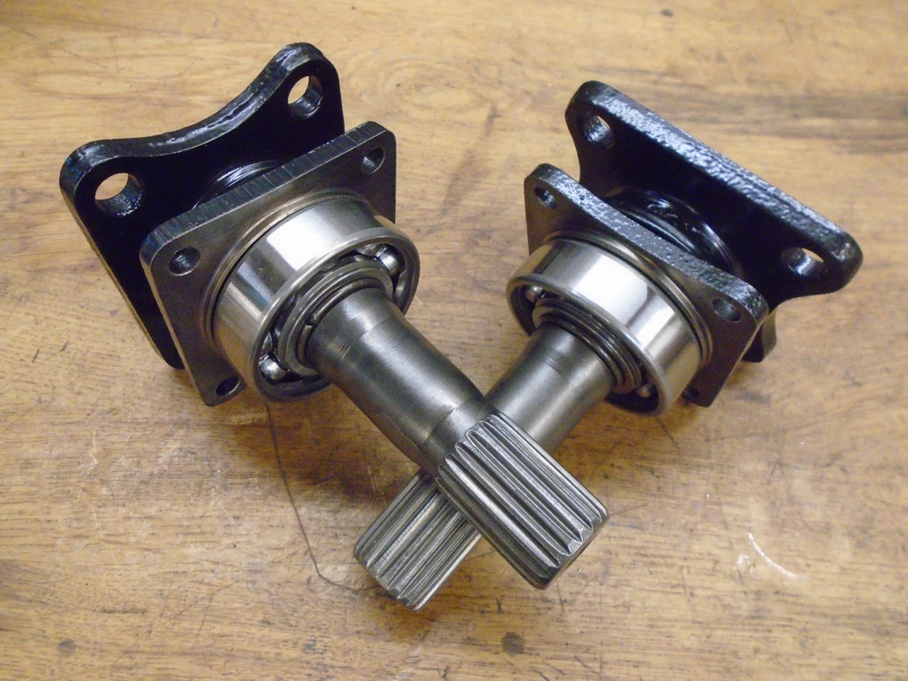
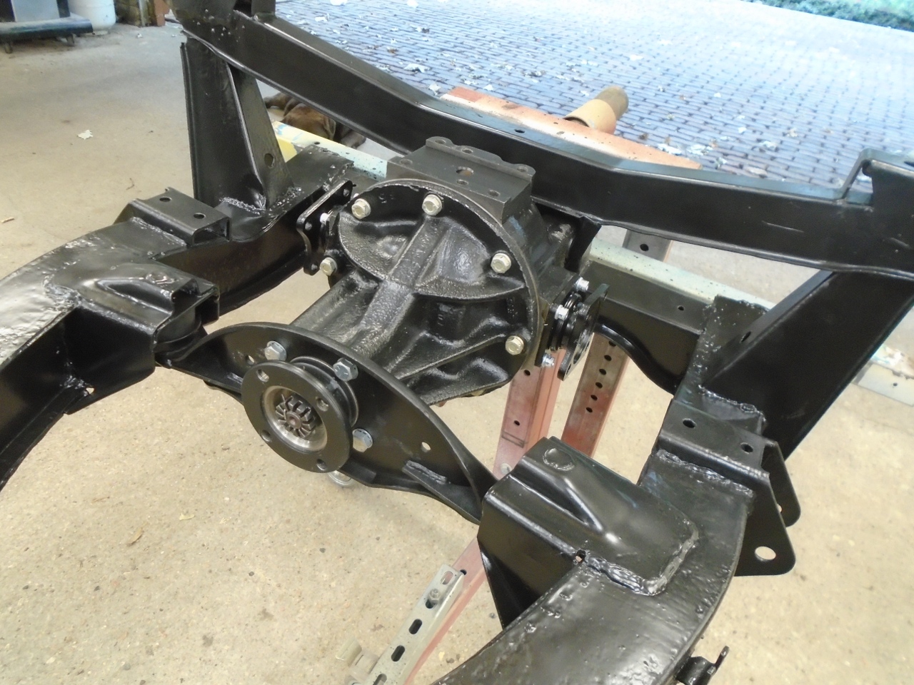
The
last task was to do the inner axles. Each one consists of a
splined shaft with flange, a seal and seal carrier, and a bearing.
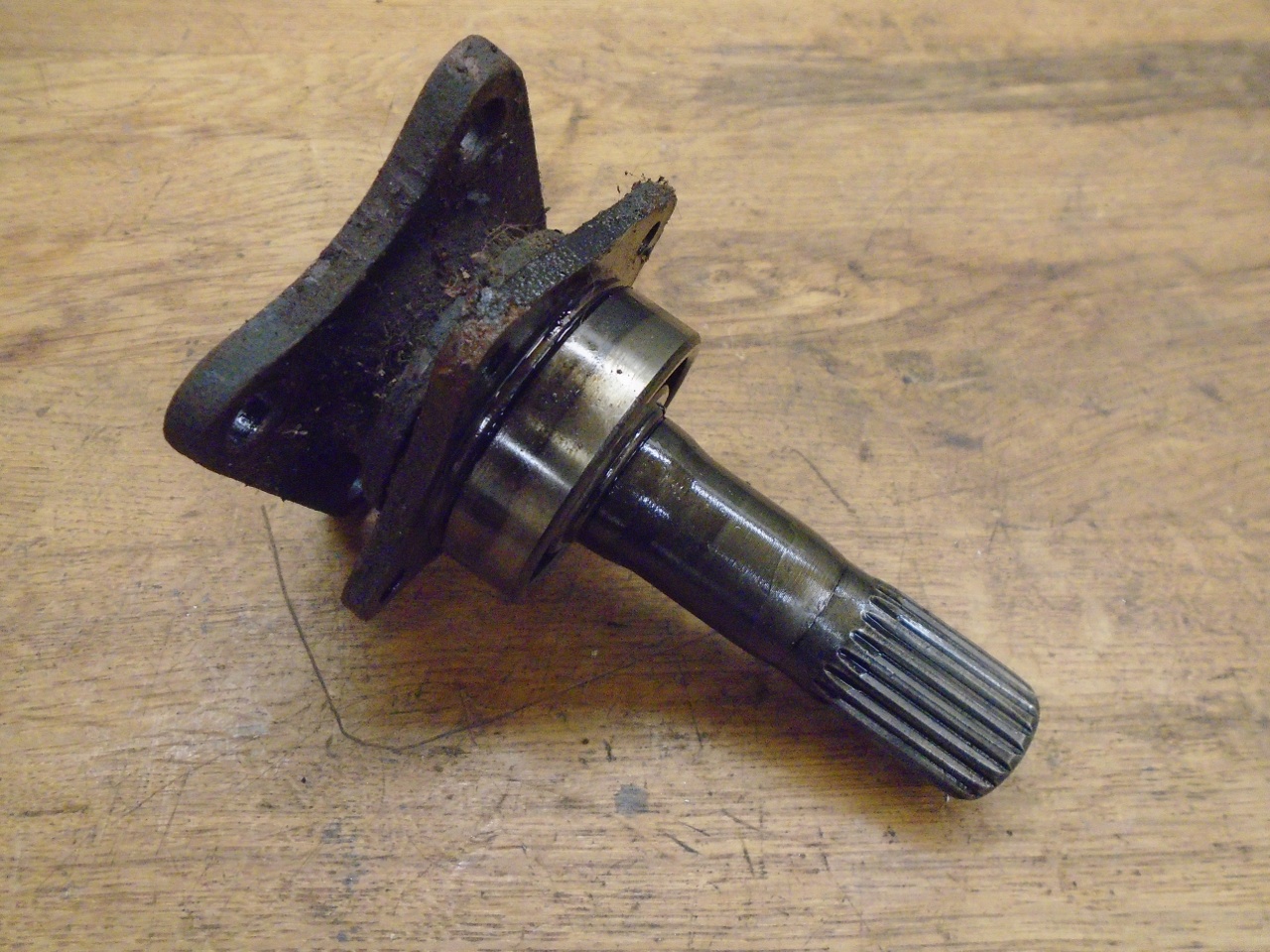
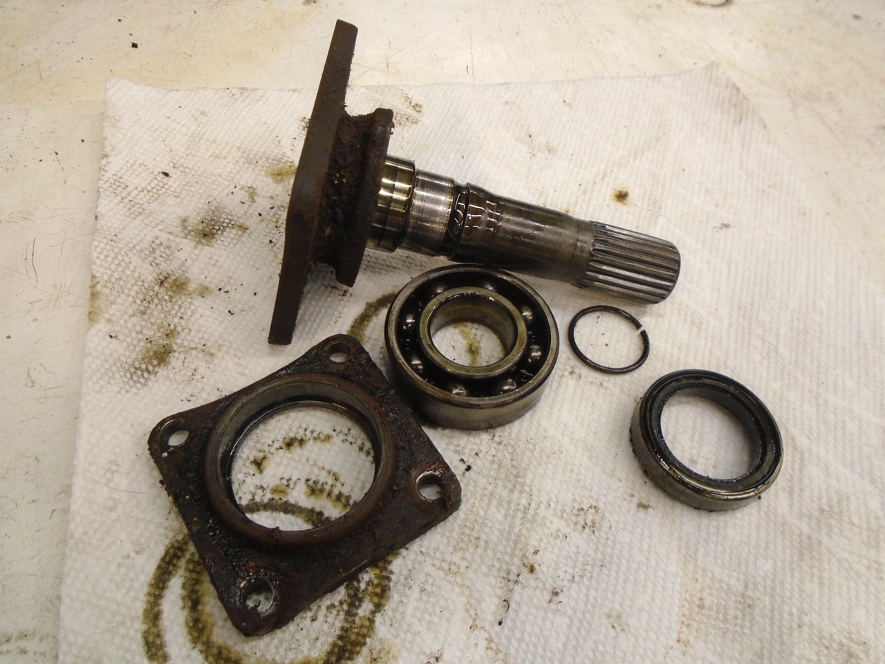
A little cleanup, new bearing and seal, and some powder coat...
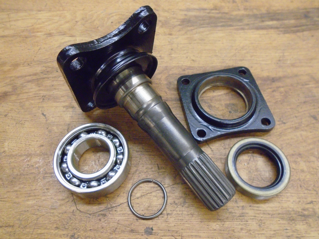
...and these dudes are ready.
Final stretch...
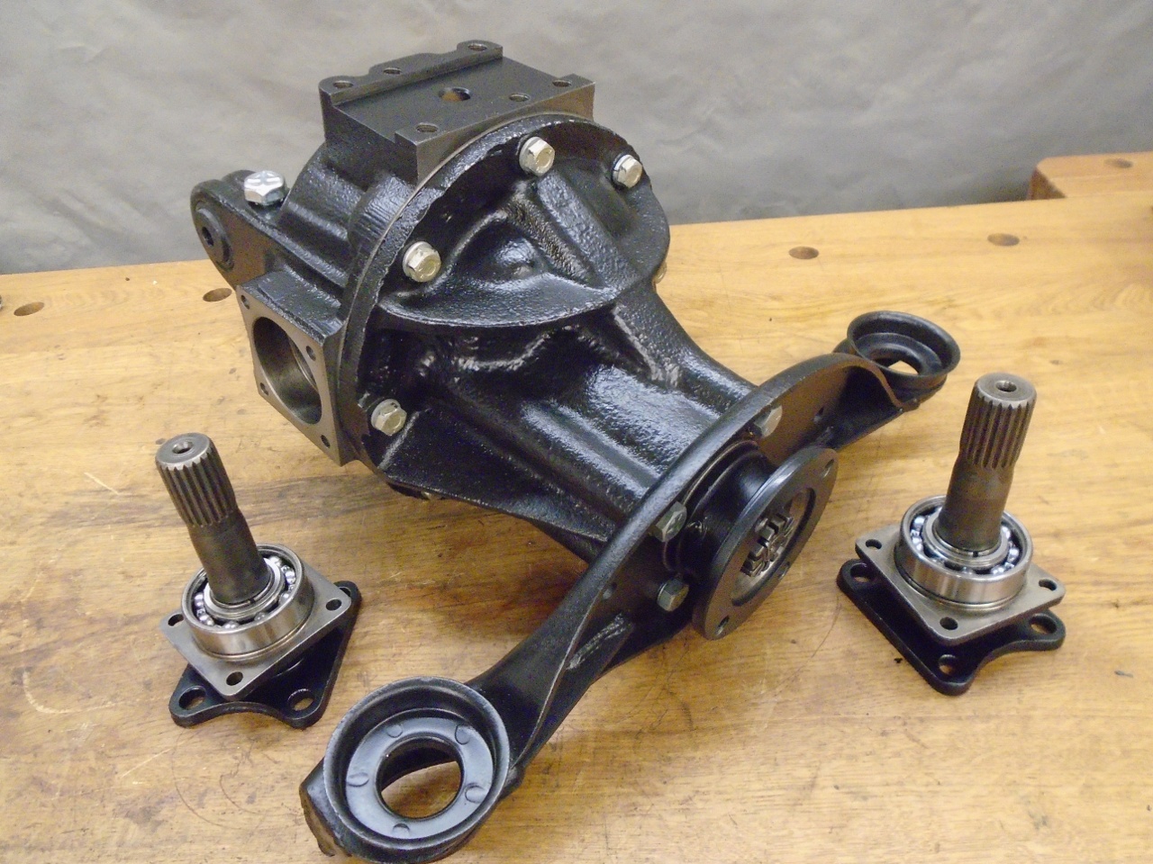
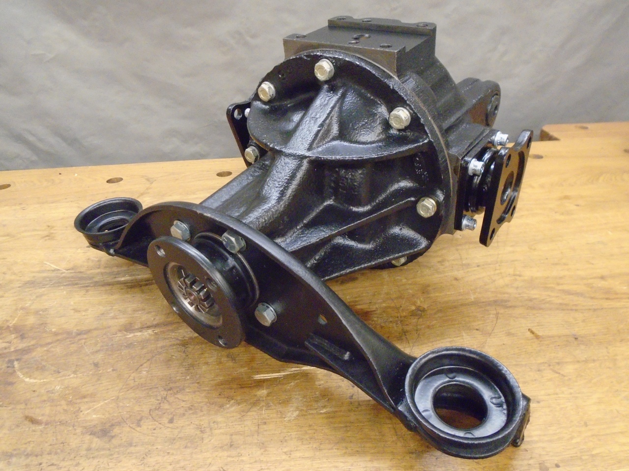
This space is begging to be filled.
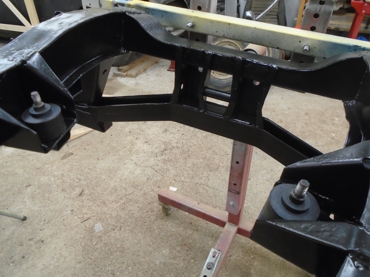
It was a piece of cake with the frame upside down.
Even
though this differential went faster than my first one, I still would
not want to do it for a living. Cost was under $200, mostly for
bearings.
Comments to Ed at elhollin1@yahoo.com
To my other GT6 pages