To Other TR6
Pages
November 22, 2014
Differential
[Click the pics for a
better view]
I've
always been terrified of differentials. I was intimidated by all
the ominous warnings about the specialized tools needed, and the
very precise clearance and preload specs. For this project, I
decided
to suck it up and at least dig into what I'd need to tackle the job.
The manuals I had didn't really ease my trepidation much at
first. Some of them started off by advising against
attempting
the rebuild, and then launched into a bewildering series of complicated
steps.
I persevered, though,
and finally deciphered and
understood the logic behind the processes. With better
understanding, I was pretty sure I could devise substitutes for the
factory tools, and have a better than even chance of being
successful. So
here is the story of this journey.
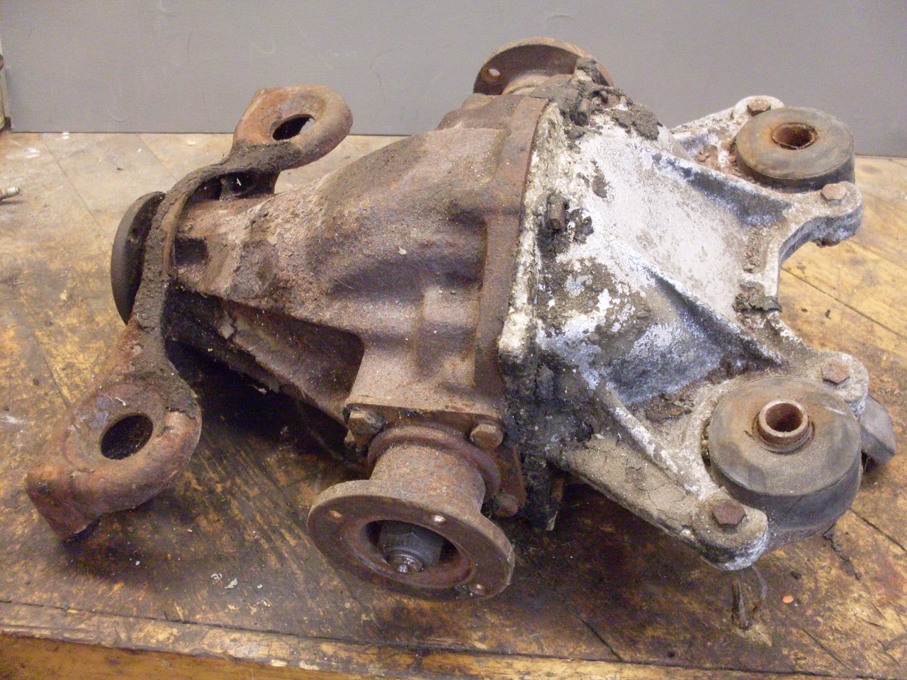
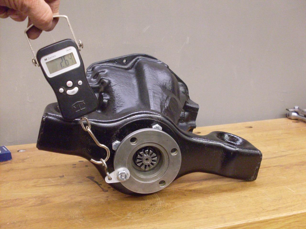
The TR6 differential is a 70 pound lump of cast iron crammed with beefy
gears and bearings. It is mounted in a fixed
position on the frame, and delivers power to the rear drive wheels
through articulated half axles.
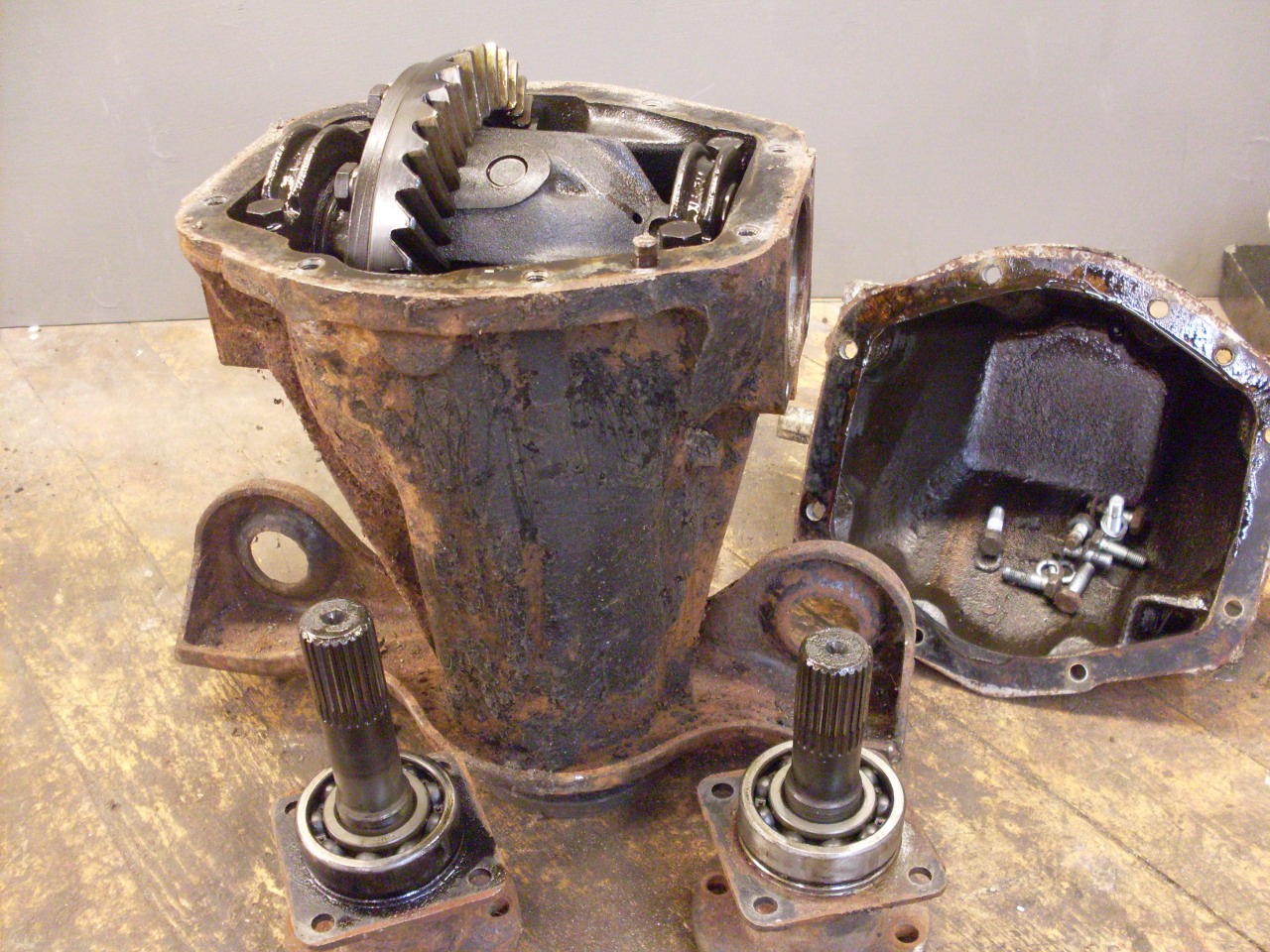
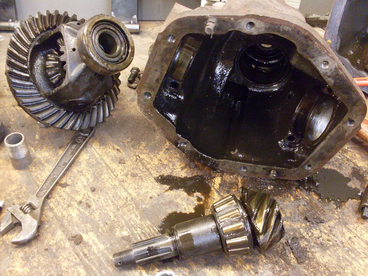
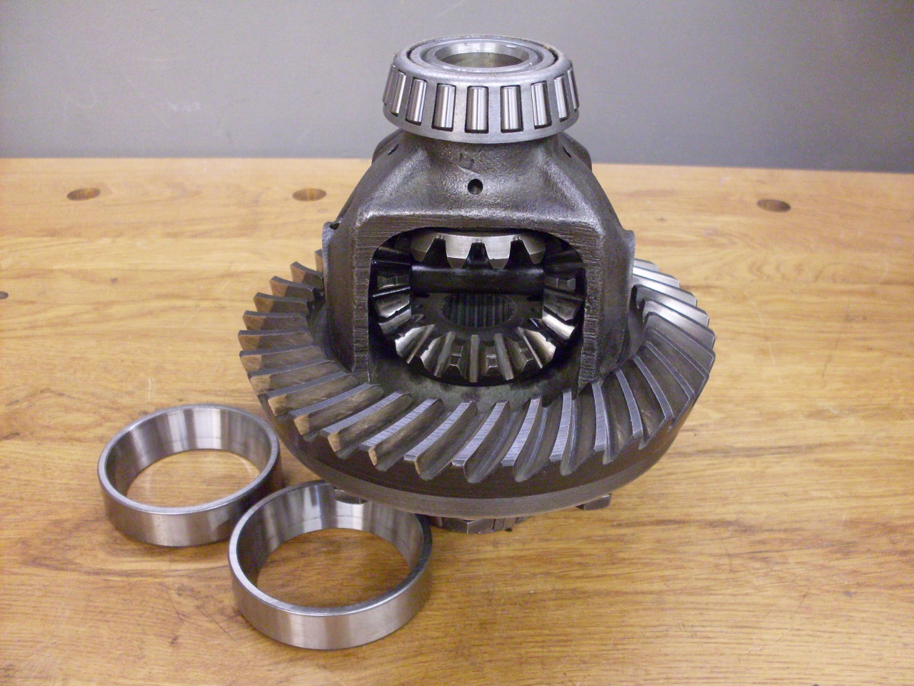
Disassembly starts with
removing the rear cover and the inner axle shaft assemblies.
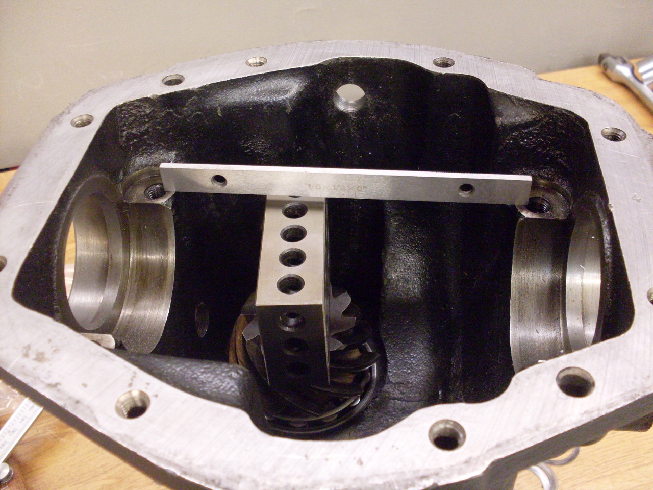
Inside, we find a 37-tooth crown wheel driven by a 10-tooth
pinion still hidden deep inside. These two gears provide a 3.70
gear ratio, proving my Haynes manual, which claims the ratio is 3.45,
wrong.
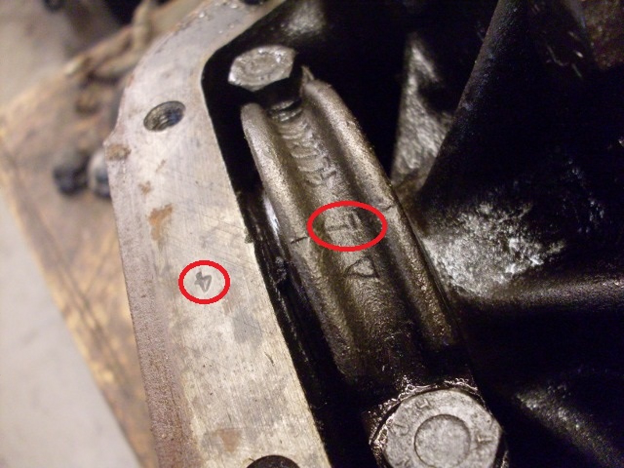
The
inner differential carrier assembly is what allows the two rear wheels
to turn at different speeds. It is held in place with two bearing
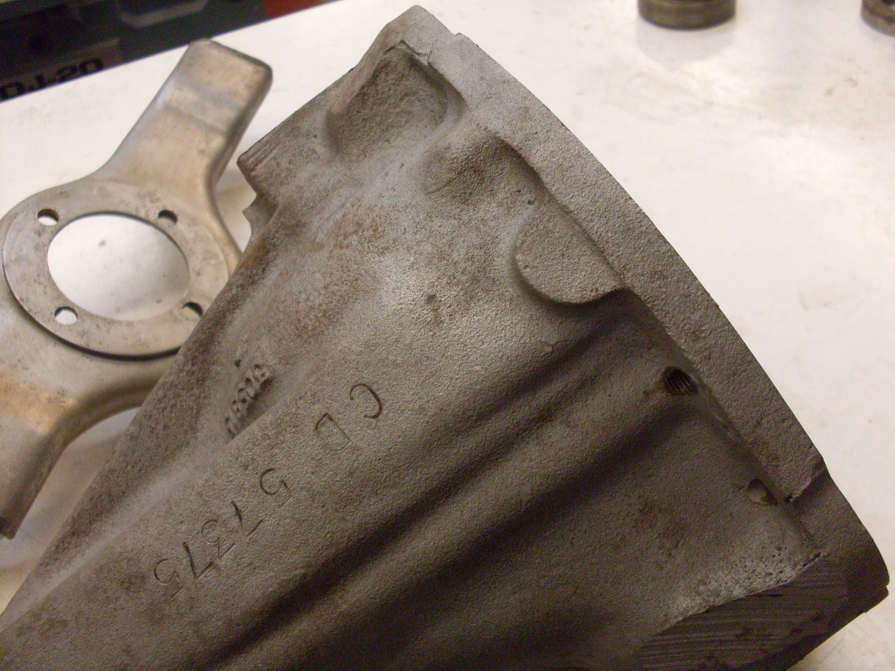
caps. The manuals say to heed the markings on the caps and
matching ones stamped onto the case flange to ensure they go back in
their original positions. I assume this is because bearing
pockets in the housing were machined with the caps on place.
On
my unit, which I'm pretty certain has never been apart before, the caps
were reversed, judging by the markings. The markings on the
other
side are the reverse of that in the pic ("4" on the cap and
"7" on
the housing flange).
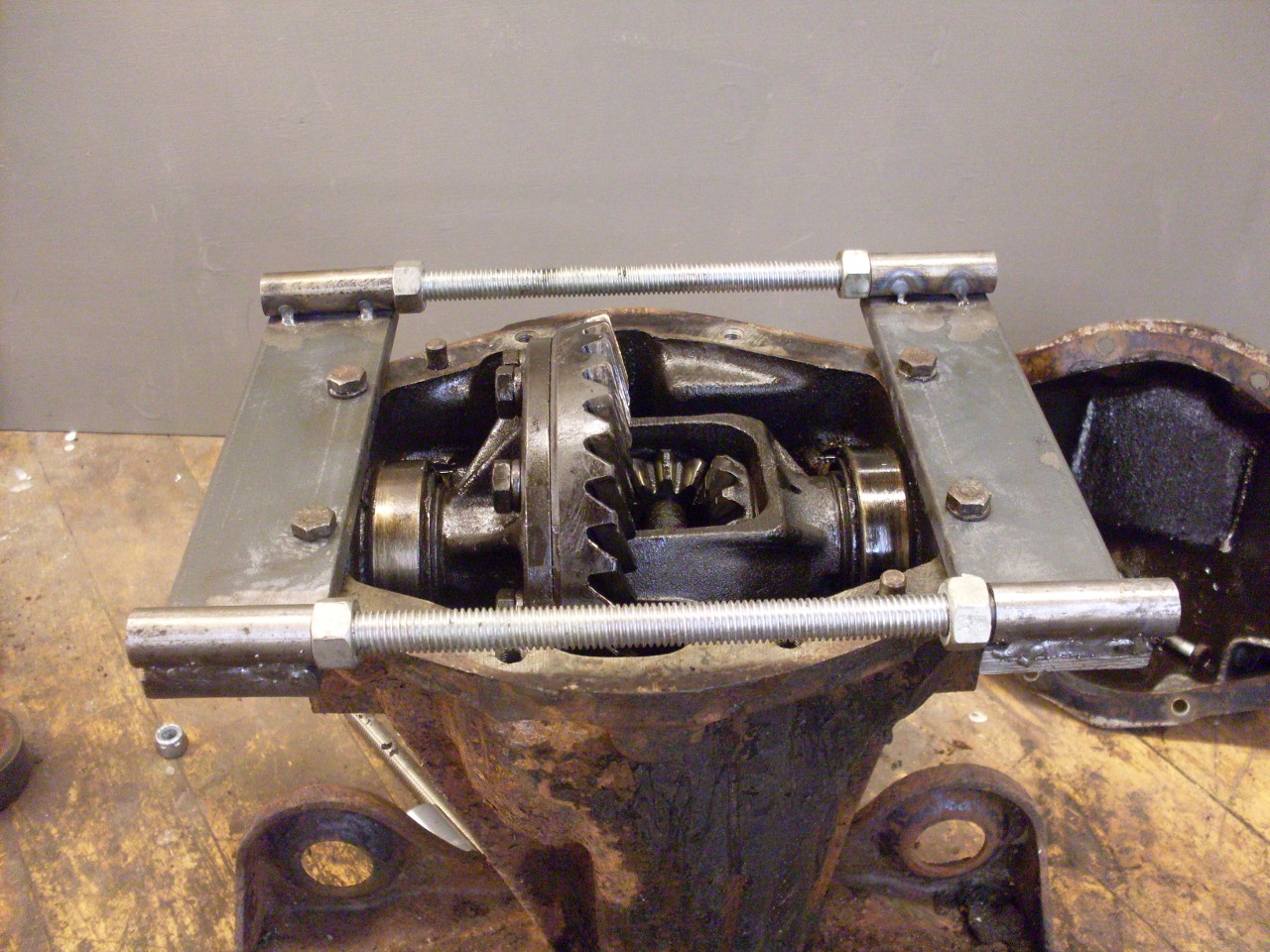
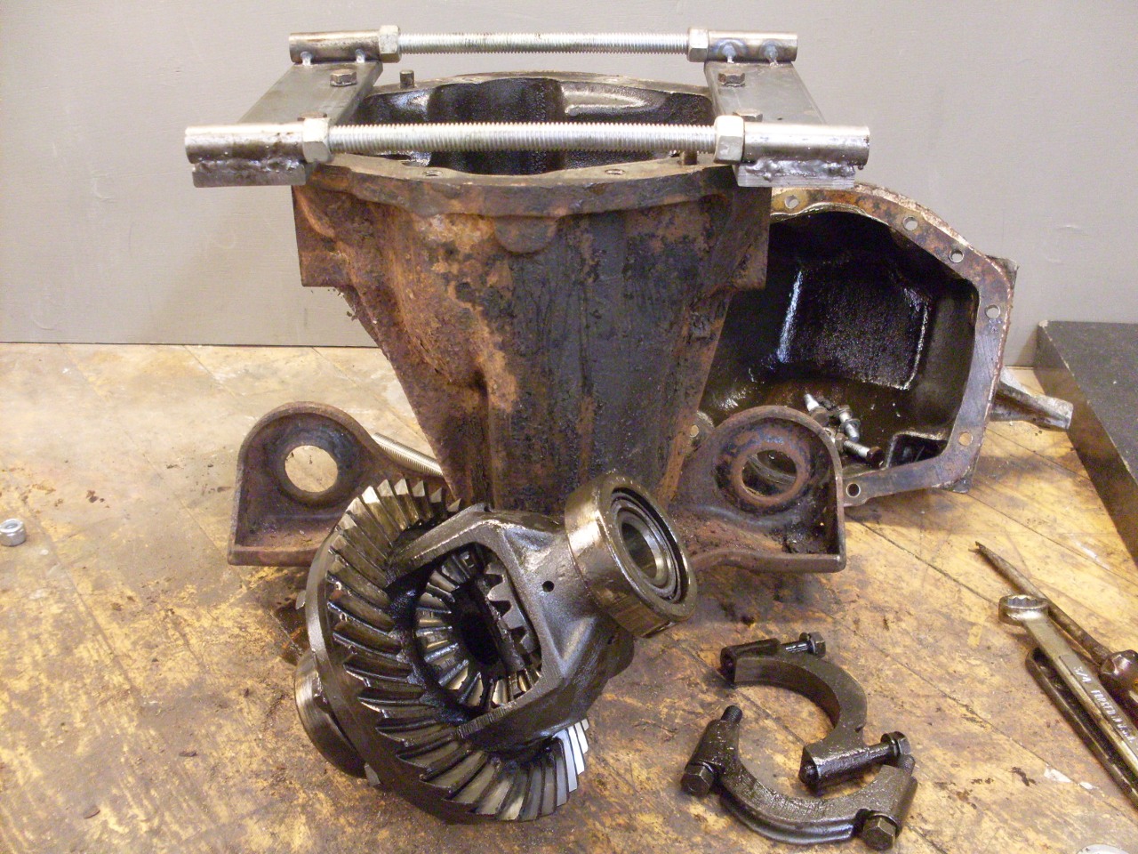
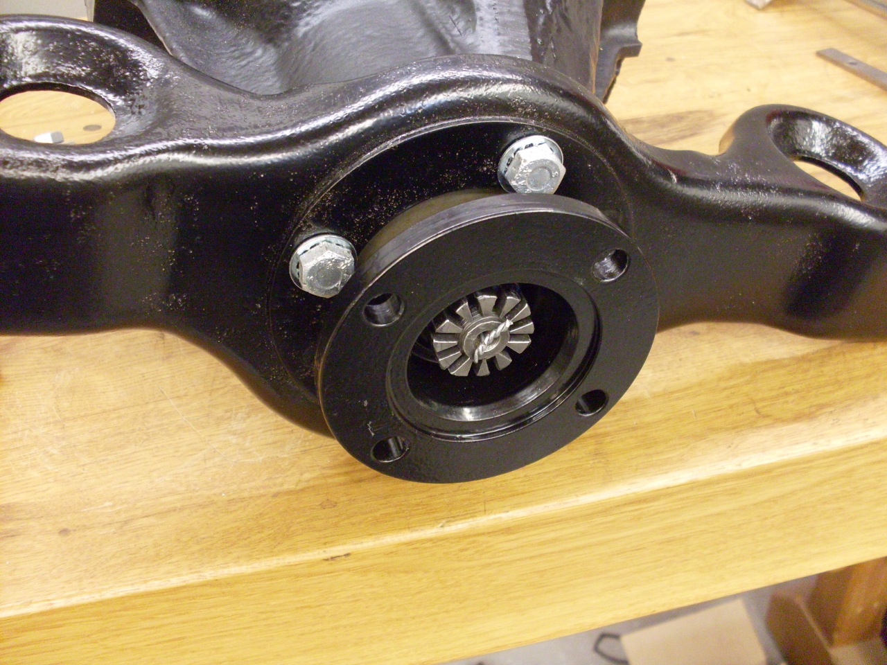
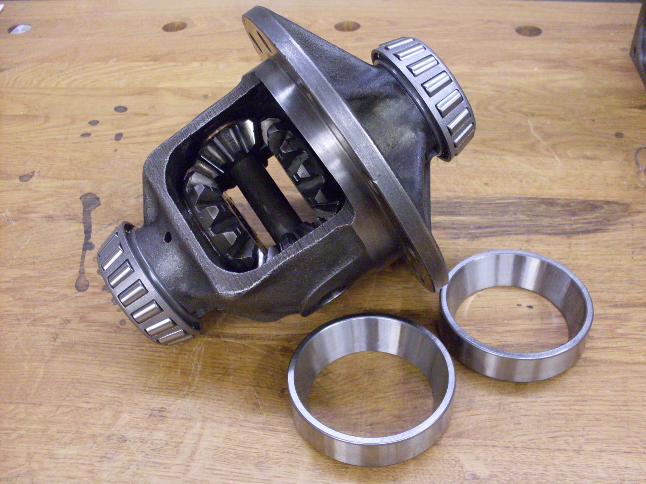
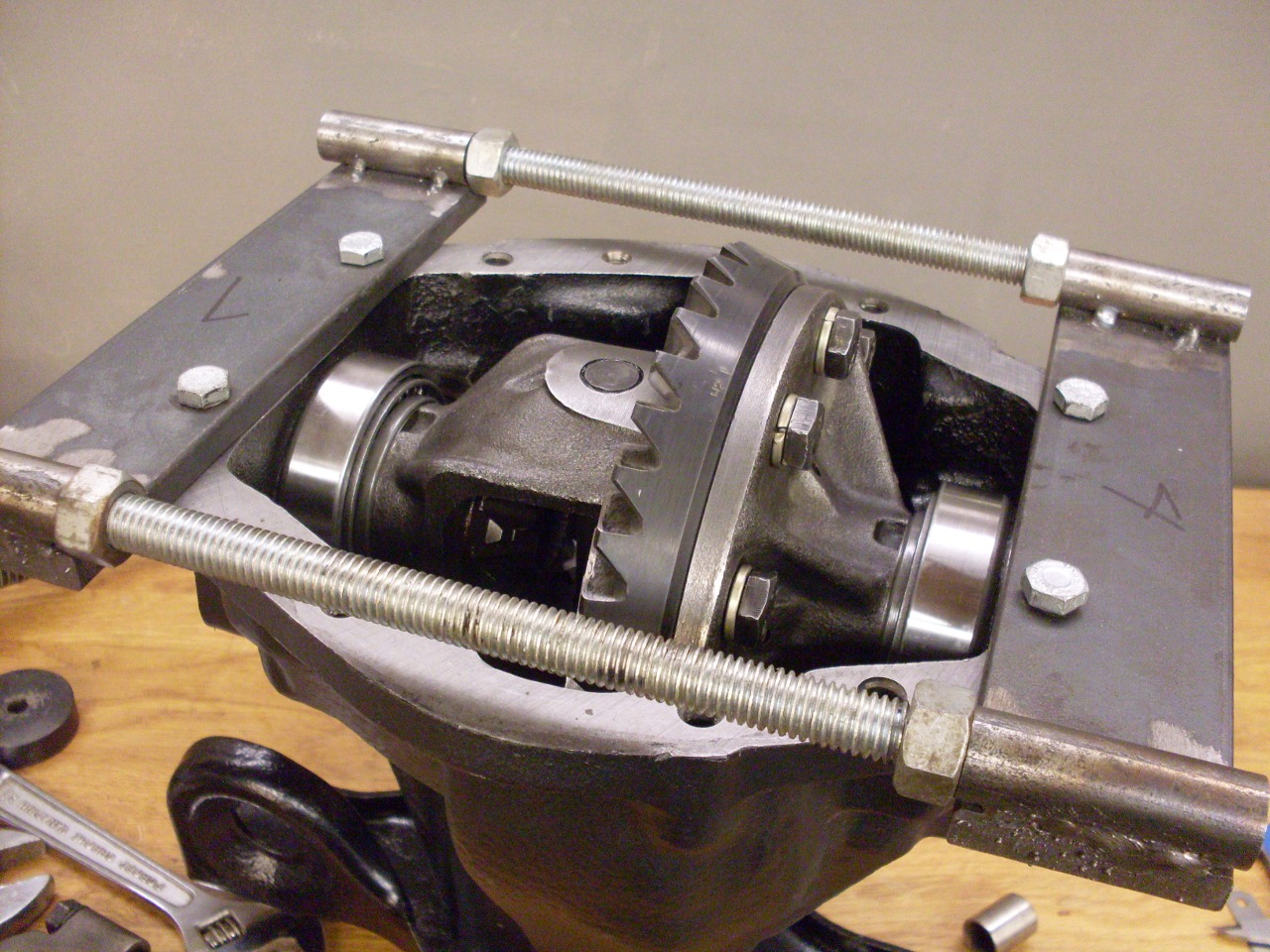
After
the caps are removed, the differential carrier still won't come out
because it is "pinched" in the case with an interference fit.
This effectively preloads the differential carrier bearings
so
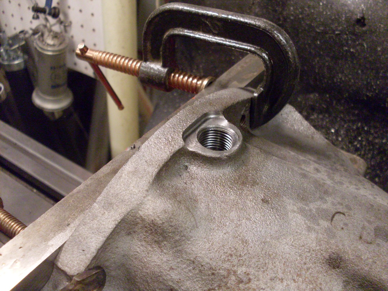
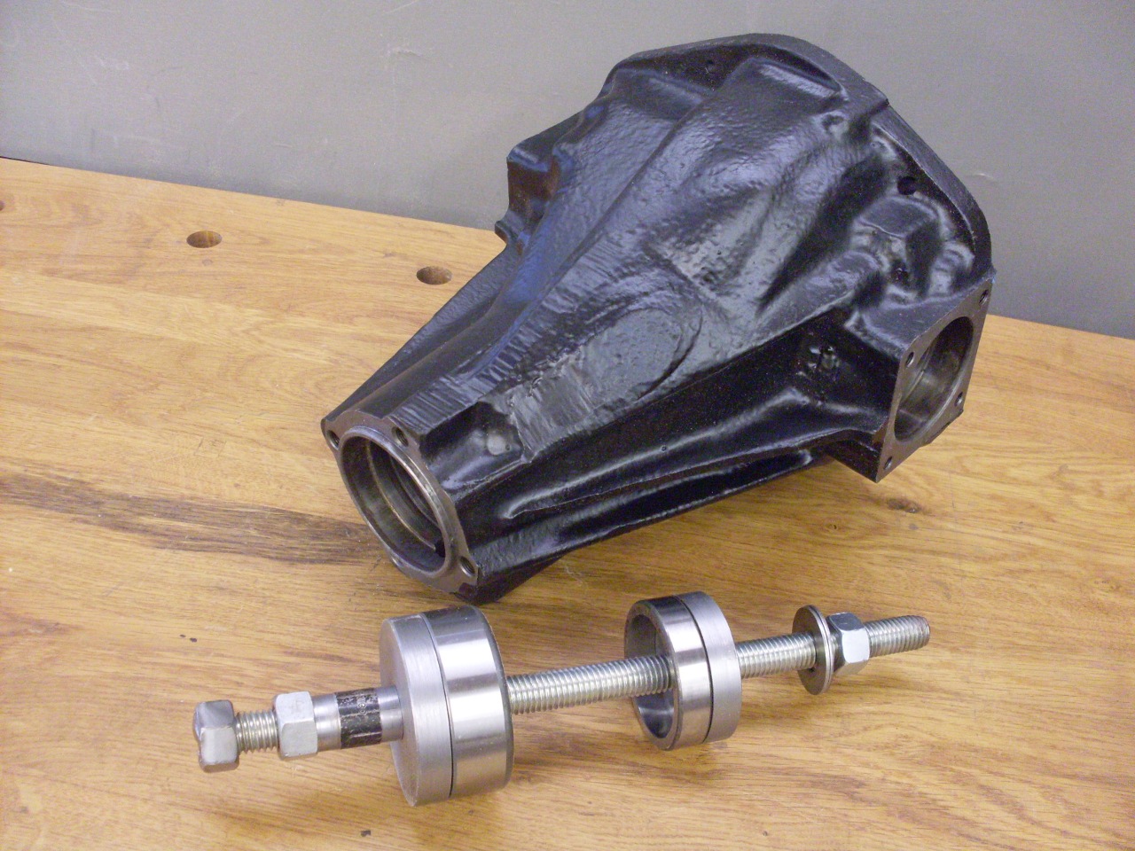
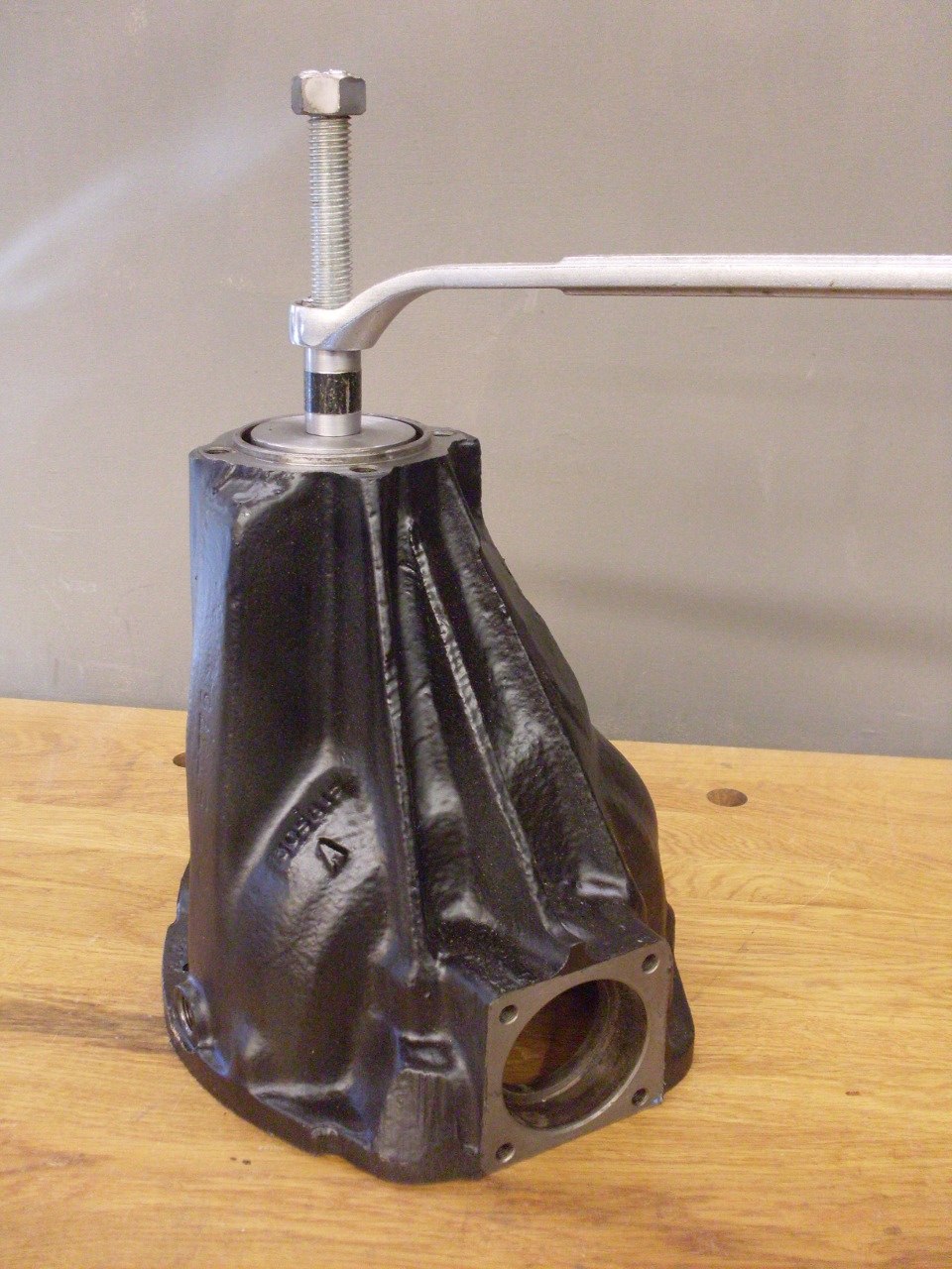
there is no play. To relieve the preload and unpinch the
differential assembly, the case has to be stretched. There is
a
factory tool for this, but many rebuilders fabricate their own.
Mine consists of a bar screwed to each end of the case, and
some
threaded rods arranged so that turning nuts on them forces the bars
apart. The tool only has to distort the case by a few
thousandths
of an inch. When it does this, the differential caririer can
be
pulled out.
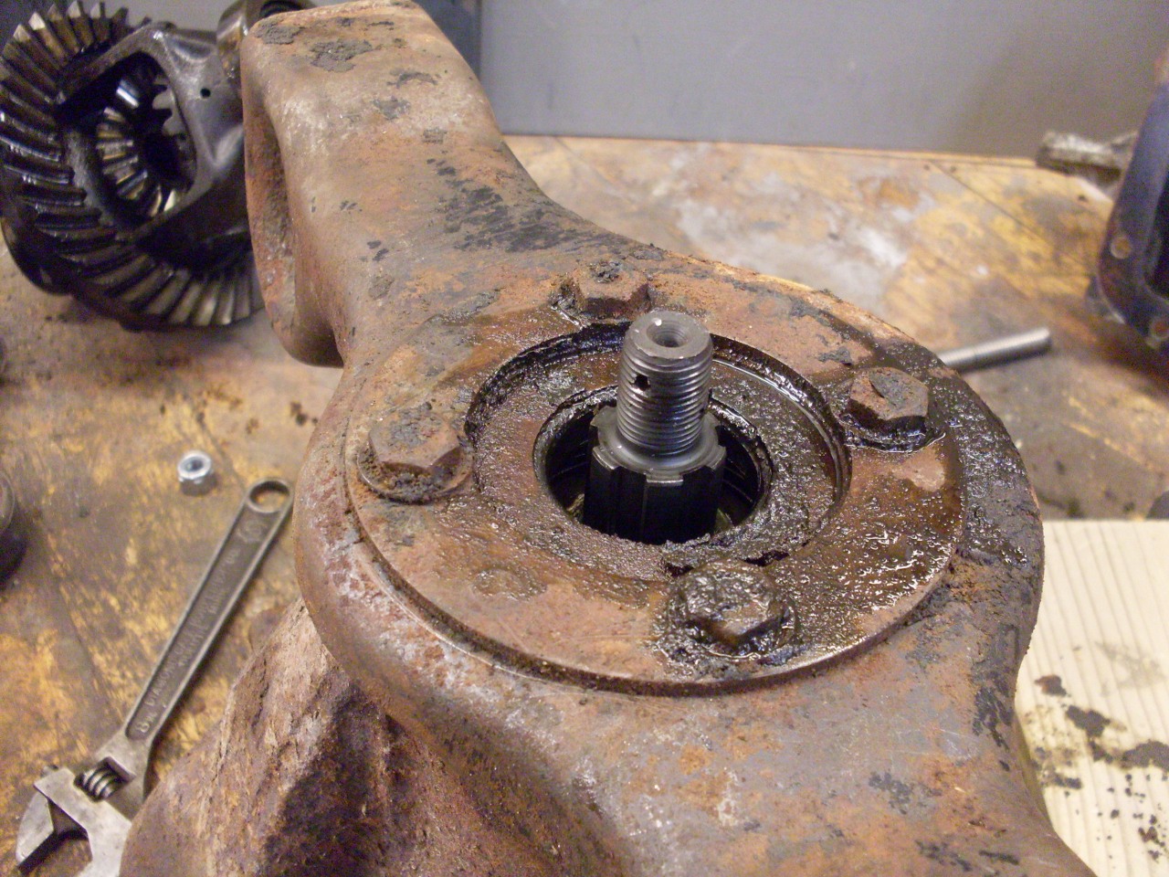
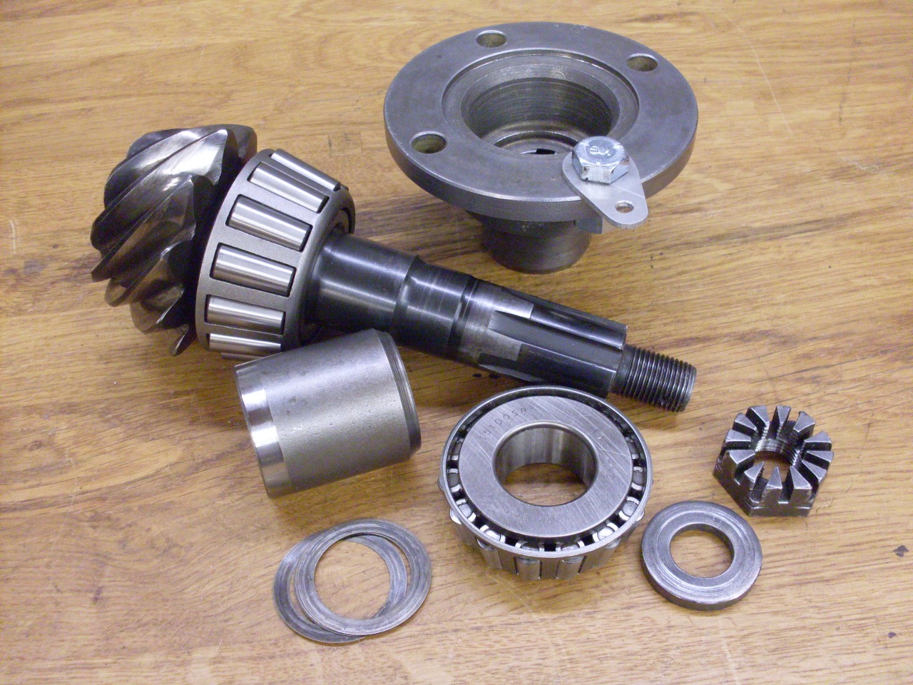
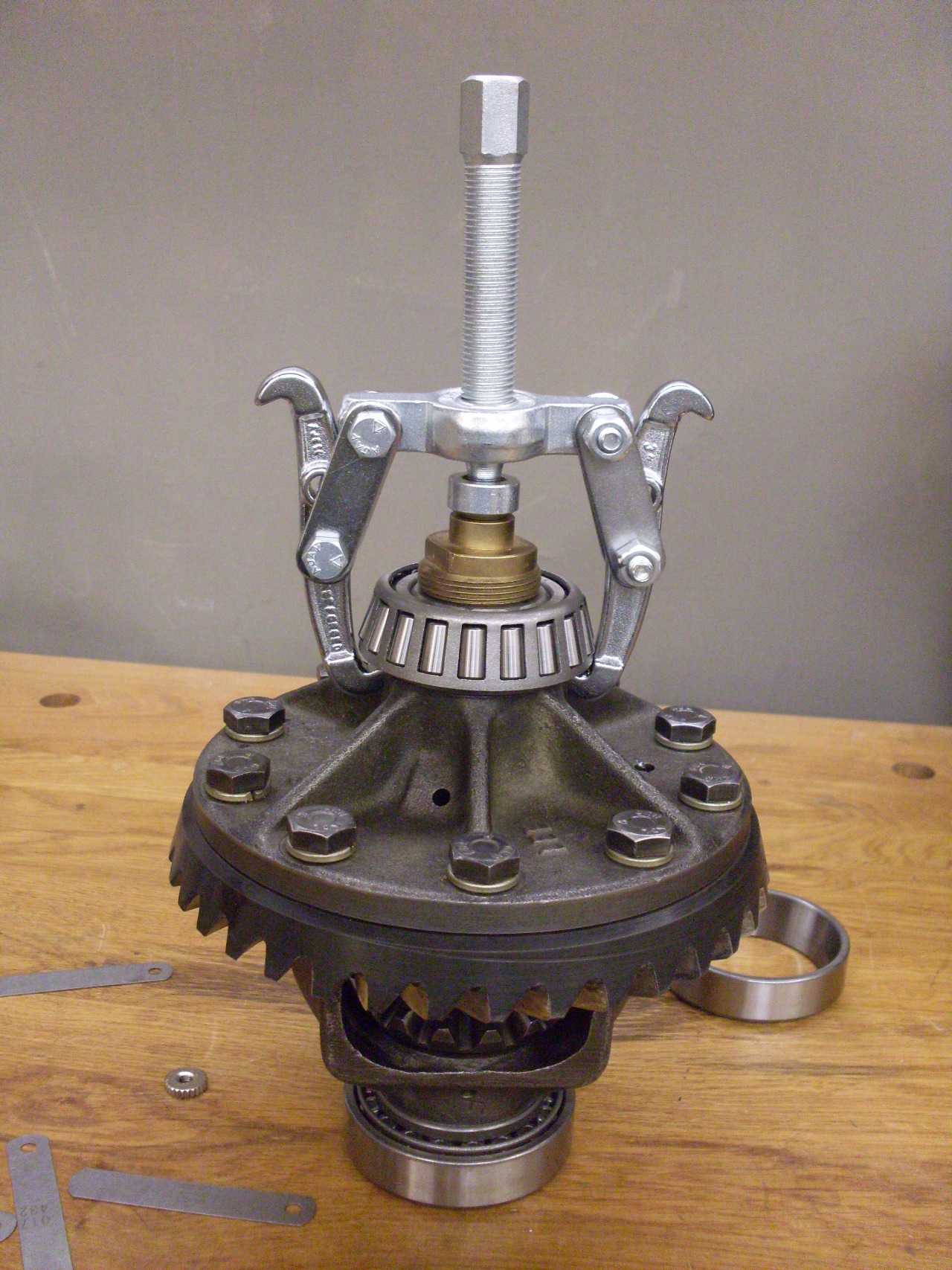
The next major part in the case is the pinion gear. It runs
in
two good sized tapered roller bearings, and can be pressed or
tapped out
after the drive flange is removed.
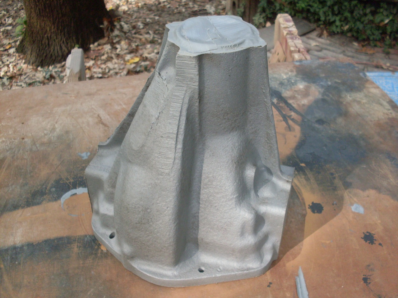
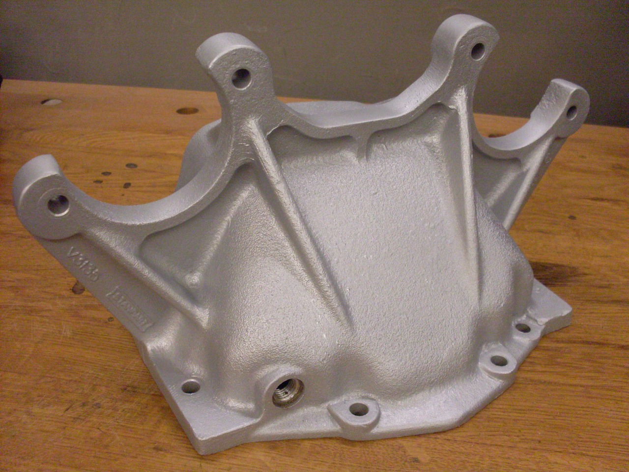
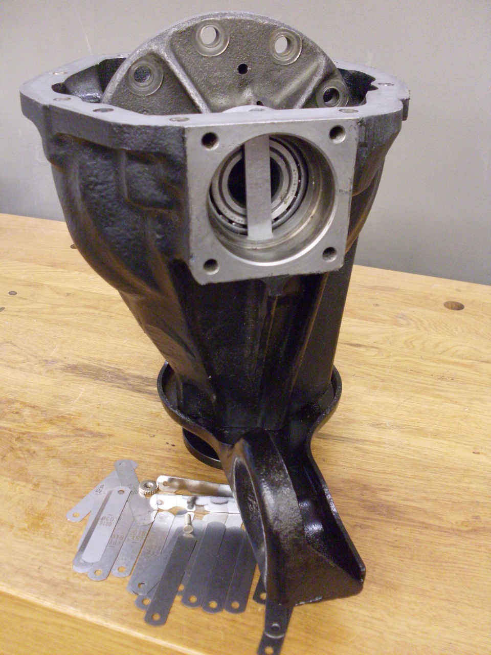
With
everything taken apart, I ordered new bearings and seals, and started
working on the case. I masked the openings and machined
surfaces
and blasted the rust and grime off of it.

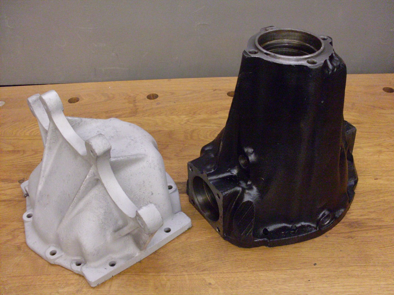
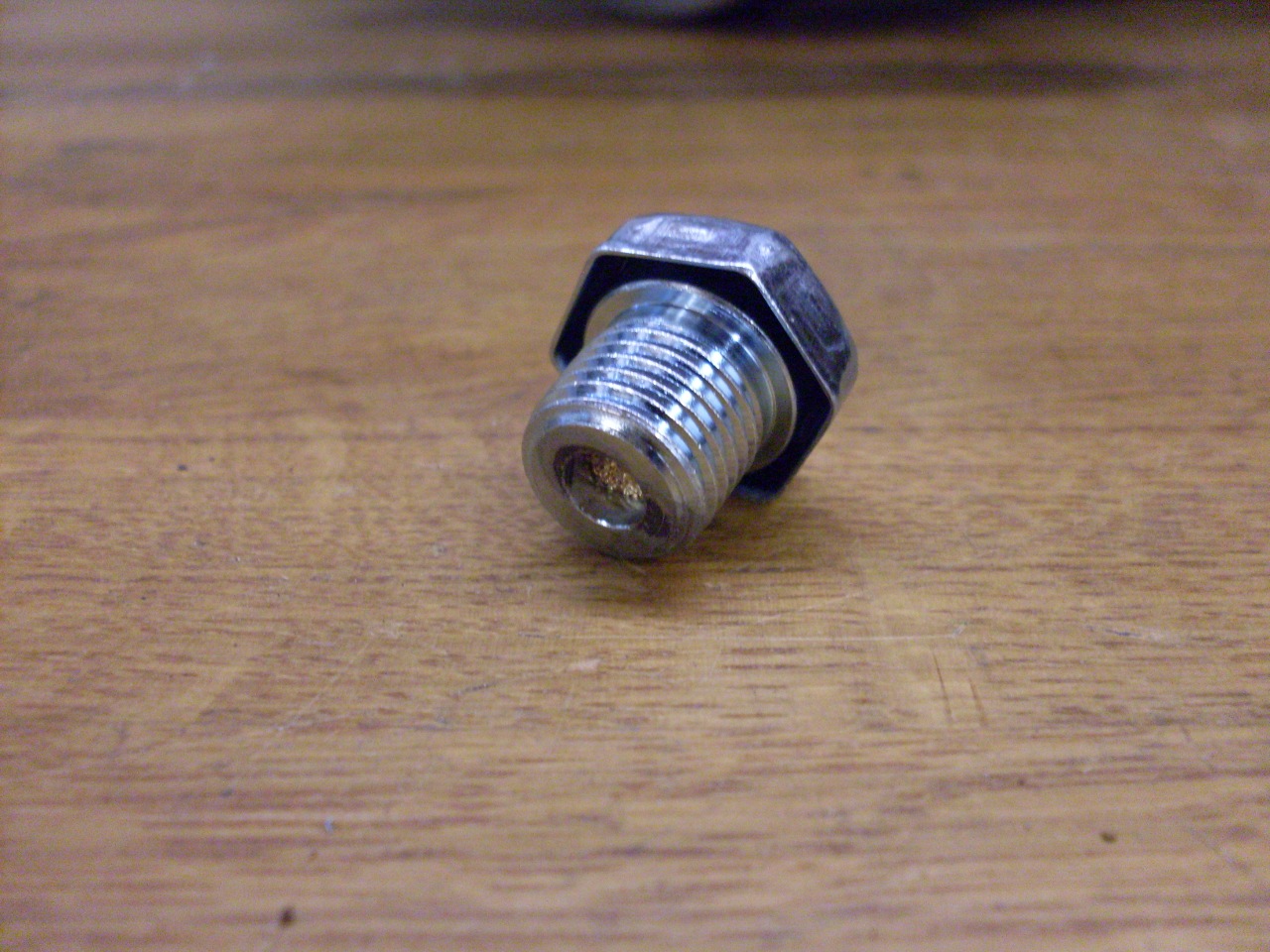
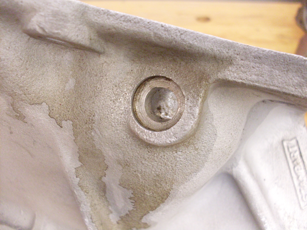
Looking
over the clean case, I noticed that there was a boss where a drain plug
would logically go, but there was no drain. This seemed odd,
so I
decided to finish the job that Triumph saved a few pennies by not doing.
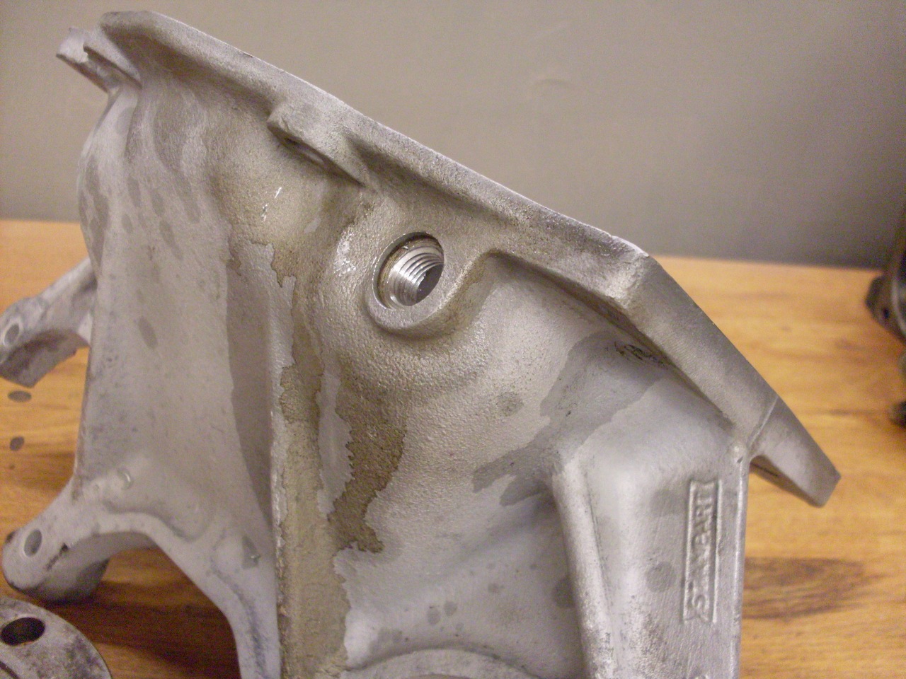
I
painted the case with a high operformance urethane paint (POR15), and
while waiting for it to dry, I blasted the aluminum rear cover.
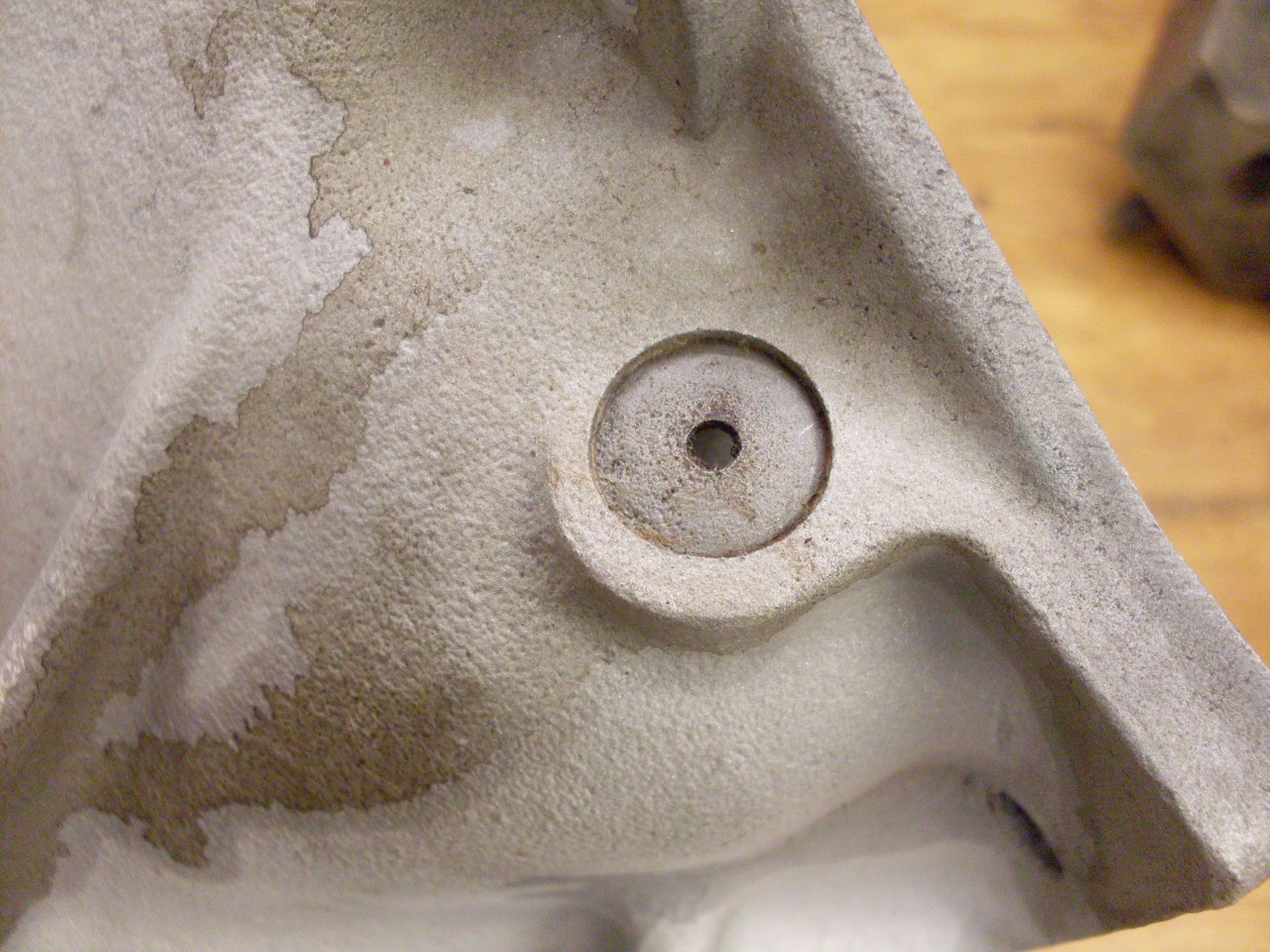
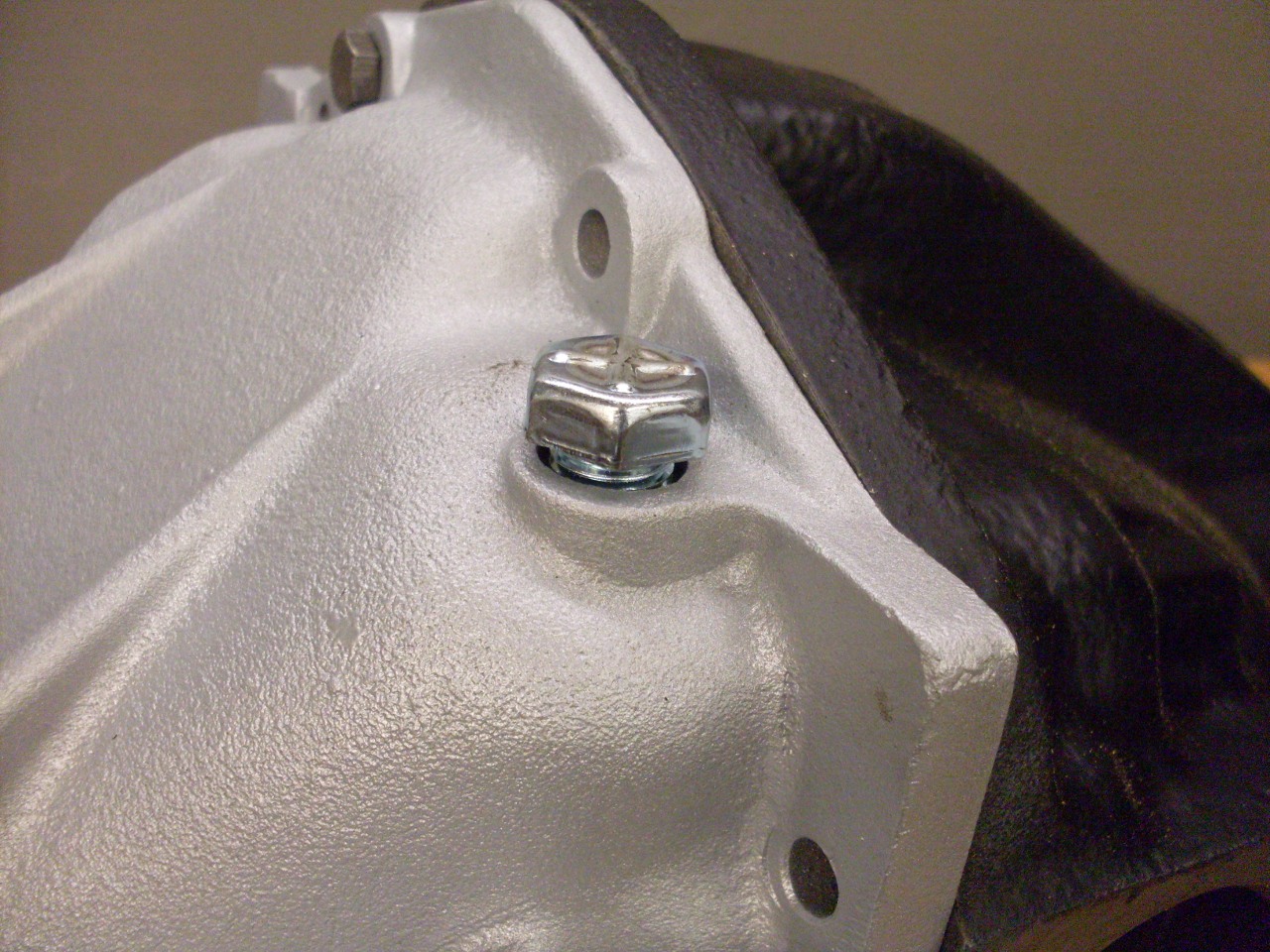
There
is a potential trouble spot on the rear cover in the vent arrangement.
The vent is important because without it, higher temperatures
will increase the pressure within the sealed case, which can force oil
past seals or gaskets. The stock vent is just a disk with a
small
hole with a cotter pin loosely in it. Apparently, the cotter
pin's job is to rattle around and keep the hole open. This
doesn't always work, and the vent can become clogged with road grime.
This is the vent with the cotter pin removed:
This
seemed like another opportunity for a simple upgrade. There
are
purpose made vents designed for differentials and
transmissions. They are much less prone to clogging and even
come with in internal filter.
I removed the vent disk
and opened up the existing vent hole and threaded it for the new vent.
Then powder coated the
cover and installed the vent. I'm not sure if the original
cover was natural or painted black.
By
this time, the replacement bearings had arrived, and I started with the
pinion assembly. The two critical adjustments for the pinion
gear
are its fore/aft position, and the preload on its two tapered roller
bearings. There is an interesting thing about the fore/aft
adjustment. The factory set the pinion position with shims
directly adjacent to the pinion head--between the head and the rear
bearing cone. The ring on the left in the left pic is a
0.060"
factory shim. However, these shims are apparently no longer
supplied by most of the regular parts suppliers. For rebuild
or
repair work, shims are supplied to go under the rear bearing's outer
race. While either method moves the pinion position, the
factory
method does it without affecting the preload, since it just moves the
pinion, not the rear bearing. I'd be interested in hearing
the
reasoning behind this situation. I decided to install the
pinion
with just the factory shim, then check pinion position.
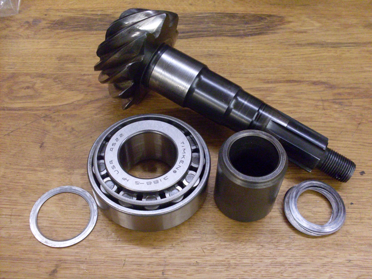
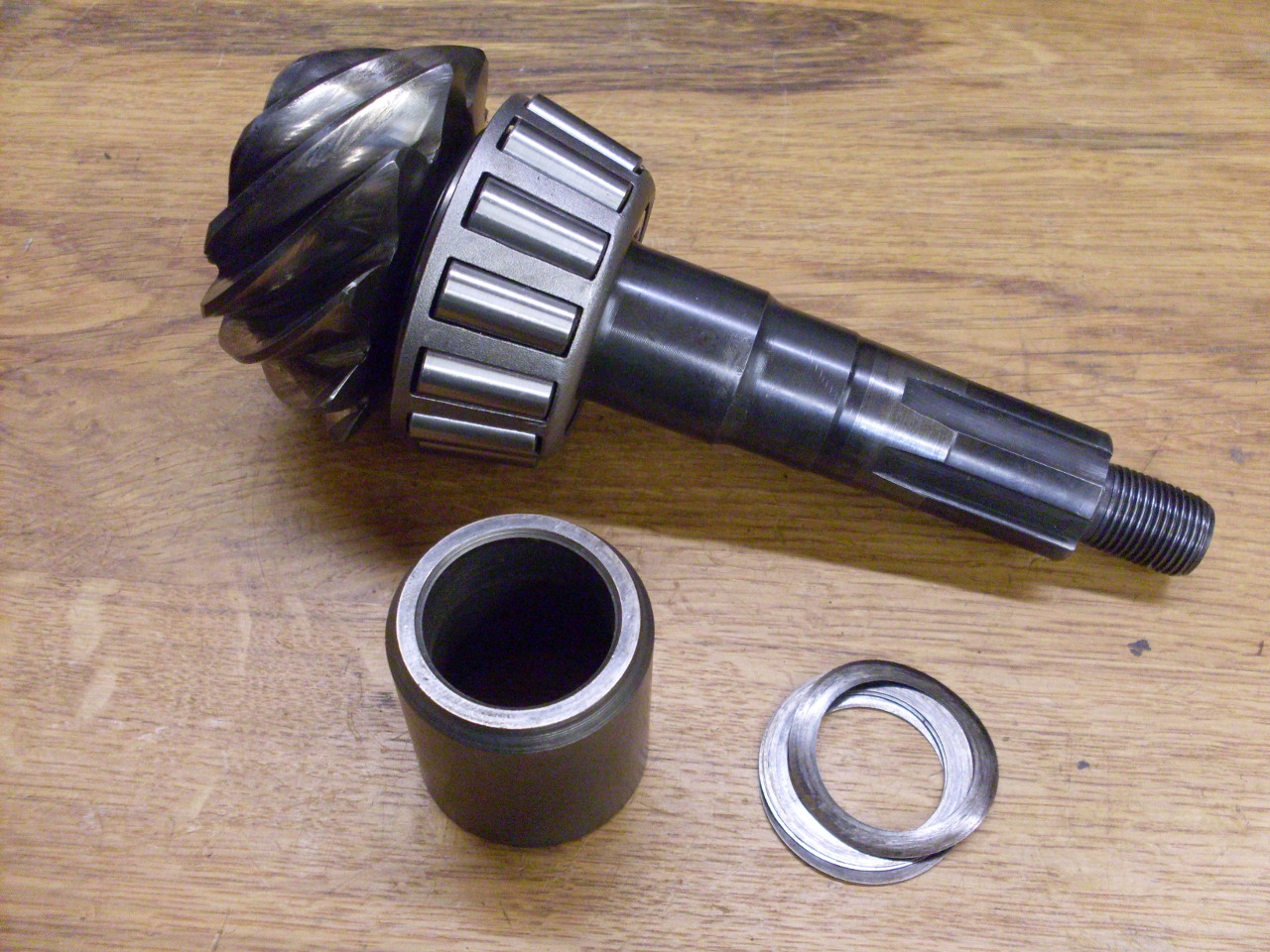
The
pinion preload is set by adjusting the distance between the two pinion
bearing cones. Most of this distance is provided by the
spacer
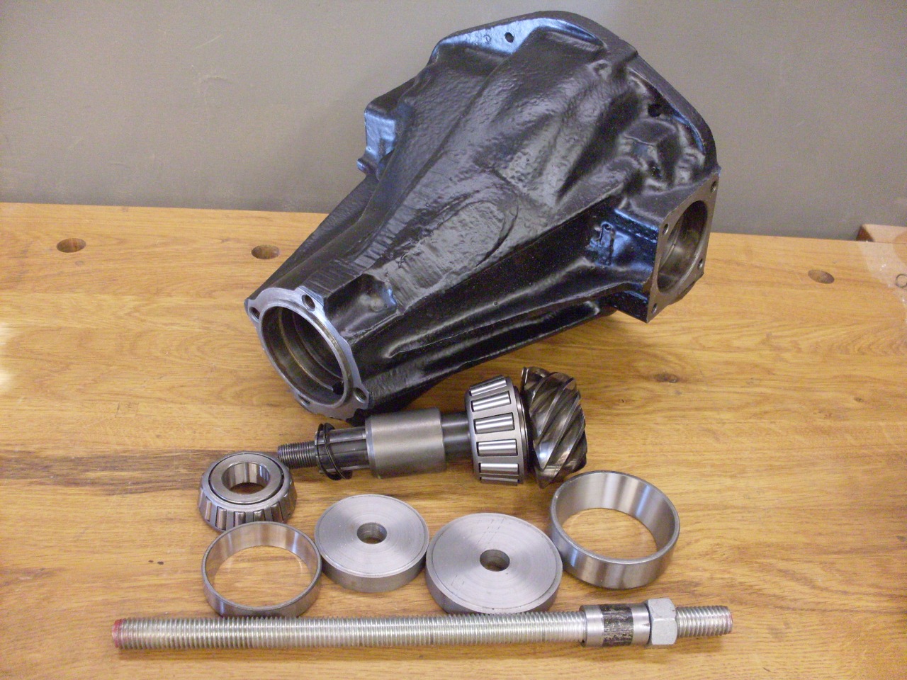
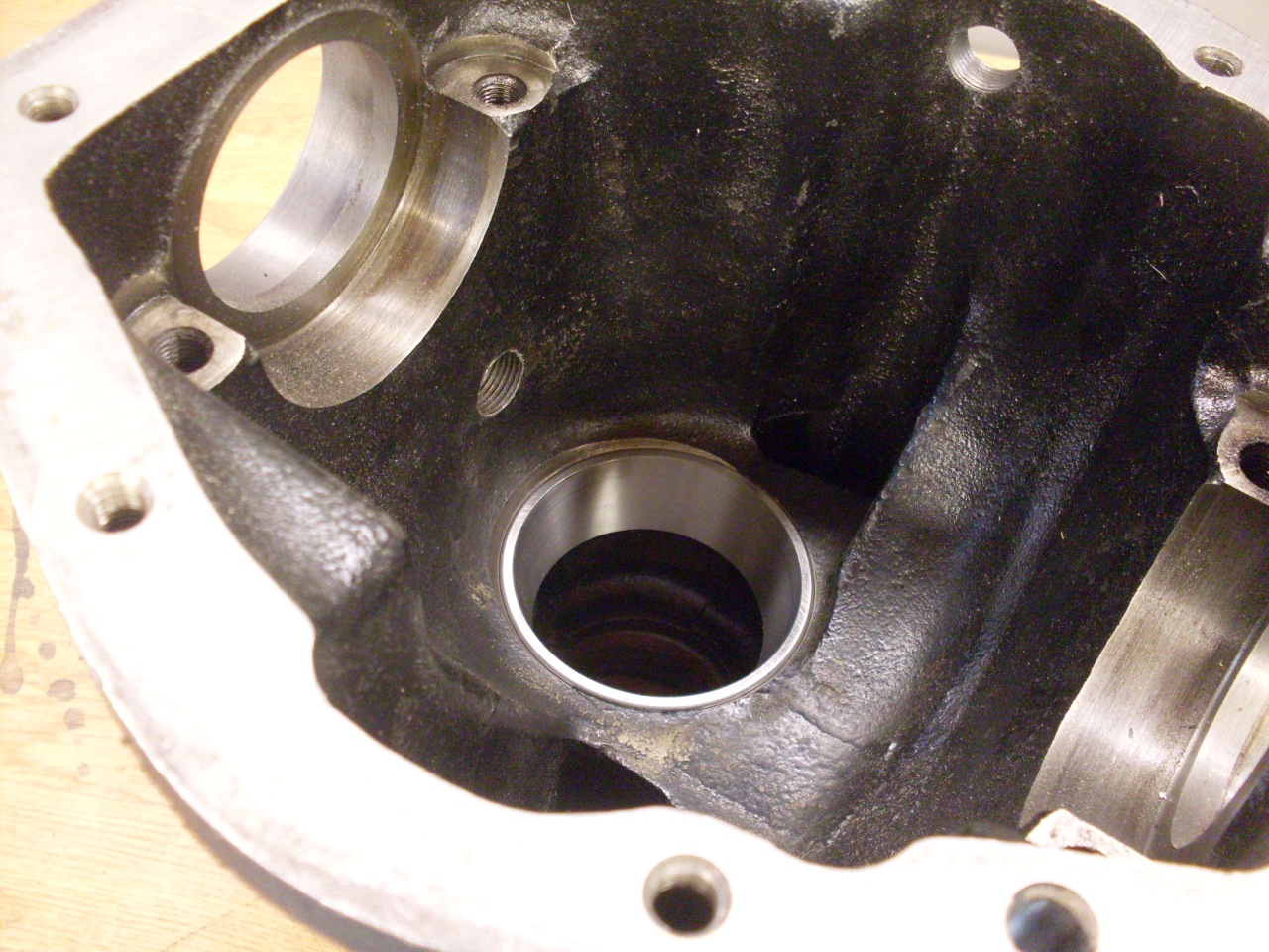
cylinder, while fine adjustment is done by adding shims. To
install the pinion assembly, the two bearing outer races must first be
installed into the case. The pics below show my version of the race
install tool. It keeps the races square and pulls them both
into
place at once.

In
the attempt to install the pinion and set its preload, I hit the first
real snag. With the pinion shaft installed with the new
bearings, I
wasn't able to get the necessary preload. With the original
preload shim pack and the pinion nut tightened to 100 ft-lb, the pinion
still had significant end play. With the shim pack removed, I
could get the end play down to essentially zero, but could still not
get anywhere near the preload spec.
After a lot of head
scratching and consultations on some TR6 forums, it seemed obvious that
something was different with the bearings. On close
inspection, I
found that the new front bearing had a much thicker internal race than
the original bearing.

The
original bearing was marked with part number 15100SR, while the
replacement bearing, supplied from one of the major British car parts
suppliers, was marked 15100. A search of bearing
manufacturer's
web sites confirmed that the two bearings are not just variants of
each other--they have one important dimension that is different.
My supplier tried to be helpful, and did acknowledge the
difference, but still insisted that the bearing they supplied was the
correct one. It baffles me that after 40 years supplying
parts
for these cars, this is apparently the first time they have heard of
this problem. In hindsight, I believe that the supplied
bearing
would probably work in the later differentials where the solid spacer is
replaced by a crush tube. Also, if a differential had a
preload
shim pack larger than about 0.036", the supplied bearing might
work if most or all of the shims were removed.
It was at this
point that I was preparing to shorten the spacer to make up for the
extra bearing thickness, but in the end, I was able to get a
correct bearing from a kind member of one of the popular TR6 forums.
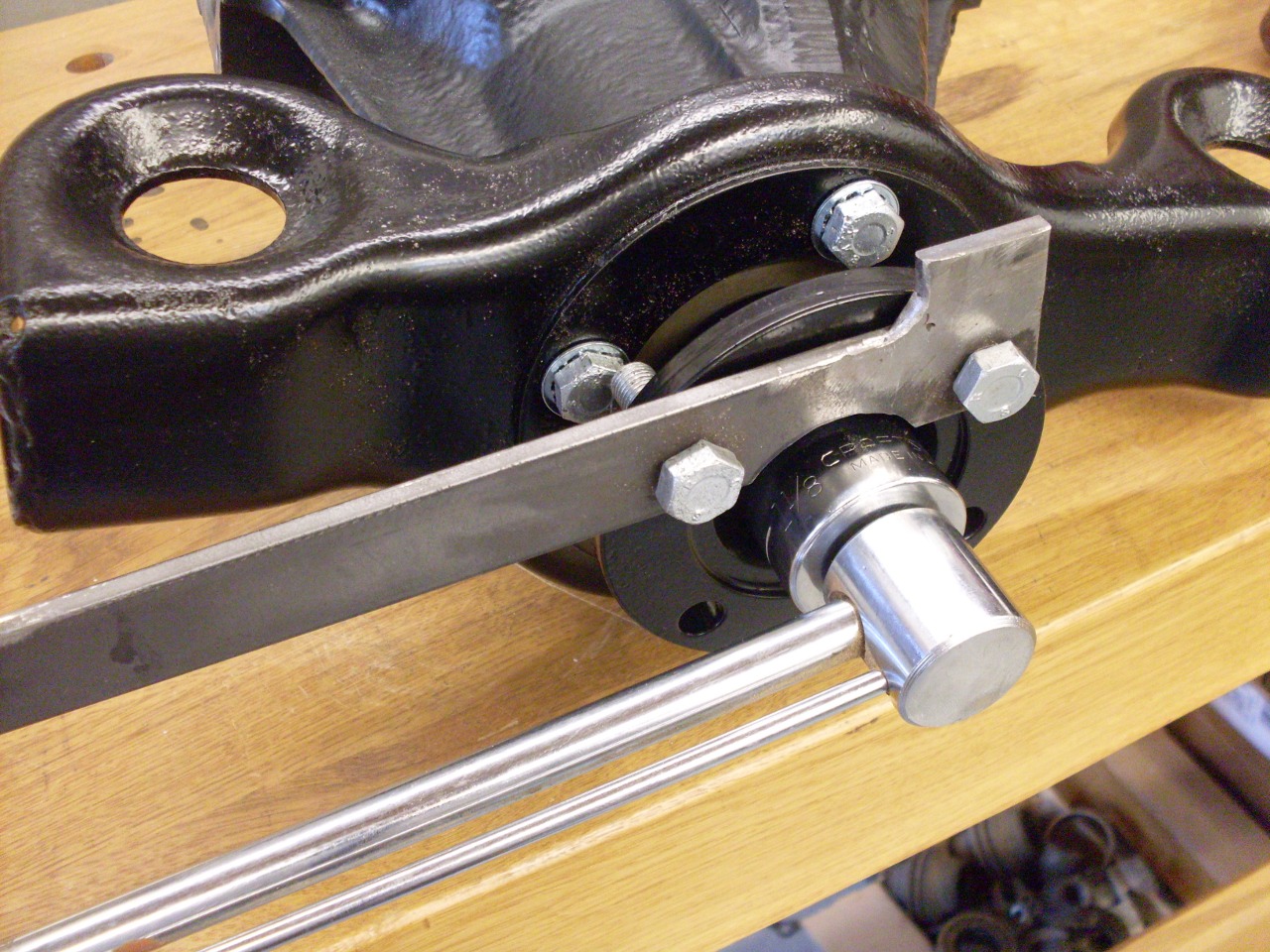
Preloading
bearings not only removes any free play, but also causes the bearings
to stiffen their rotation. The preload for the pinion is
correct
when it takes 15 to 18 inch-pounds of torque to rotate the shaft.
Torque
can be easily determined by measuring the force required to turn the
shaft when applied at the end of an arm of known length.
The product of the force and the arm length is the torque.
It took me three iterations of adjusting the preload shim
pack to
get the preload within spec.
The
final check on the pinion is its fore/aft position.
There is
a fancy factory tool for this which probably can't be found, but a
little tinkering produced a way to accurately determine pinion
position. The block and bar in the pic are precision
machinist's
tools, but aren't really expensive. The bar is 0.500" high,
and
the block is 2.000" inches high. Measuring with a caliper
from
the top of the bar to the top of the block, and doing a little
arithmetic told me that the pinion position was correct.
This
method is based loosely on one described in one of the very helpful "Six Tech
Manuals", available here:
http://www.74tr6.com/pdfs/Differential.pdf
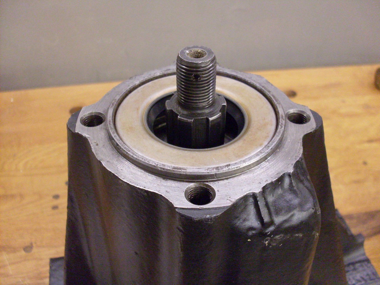
With
the pinion finally in good shape, I installed the new oil seal, added
the powder coated mounting plate, and did the final torque of the
pinion nut.
Next
up was the differential carrier. It carries the crown gear
which
meshes with the pinion, and also two sun and two planet gears inside,
which allow the two rear wheels to turn at different speeds.

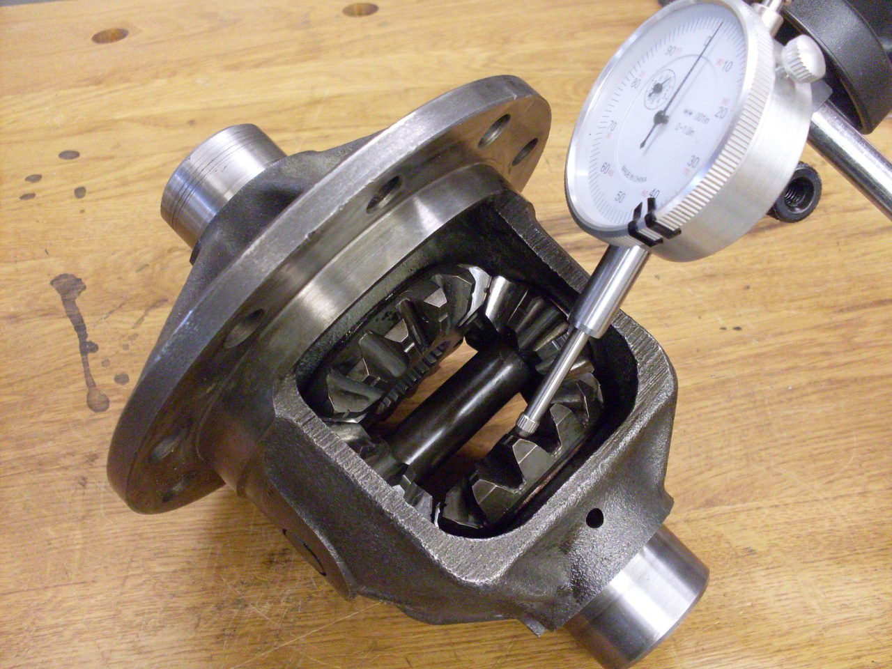
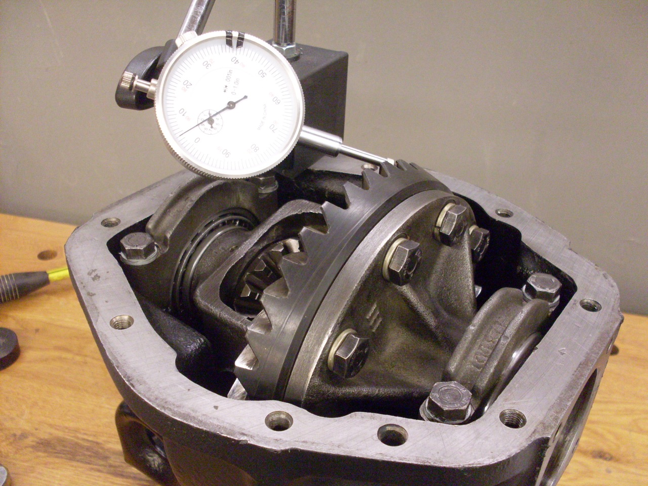
The
goal for the sun/planet gear arrangement is zero backlash among all the
gears. Backlash is adjusted by varying the thickness of the
spherical thrust washers behind the planet gears. I could
easily
detect backlash in my gears. It only measured about 0.002",
but
was easy to feel.
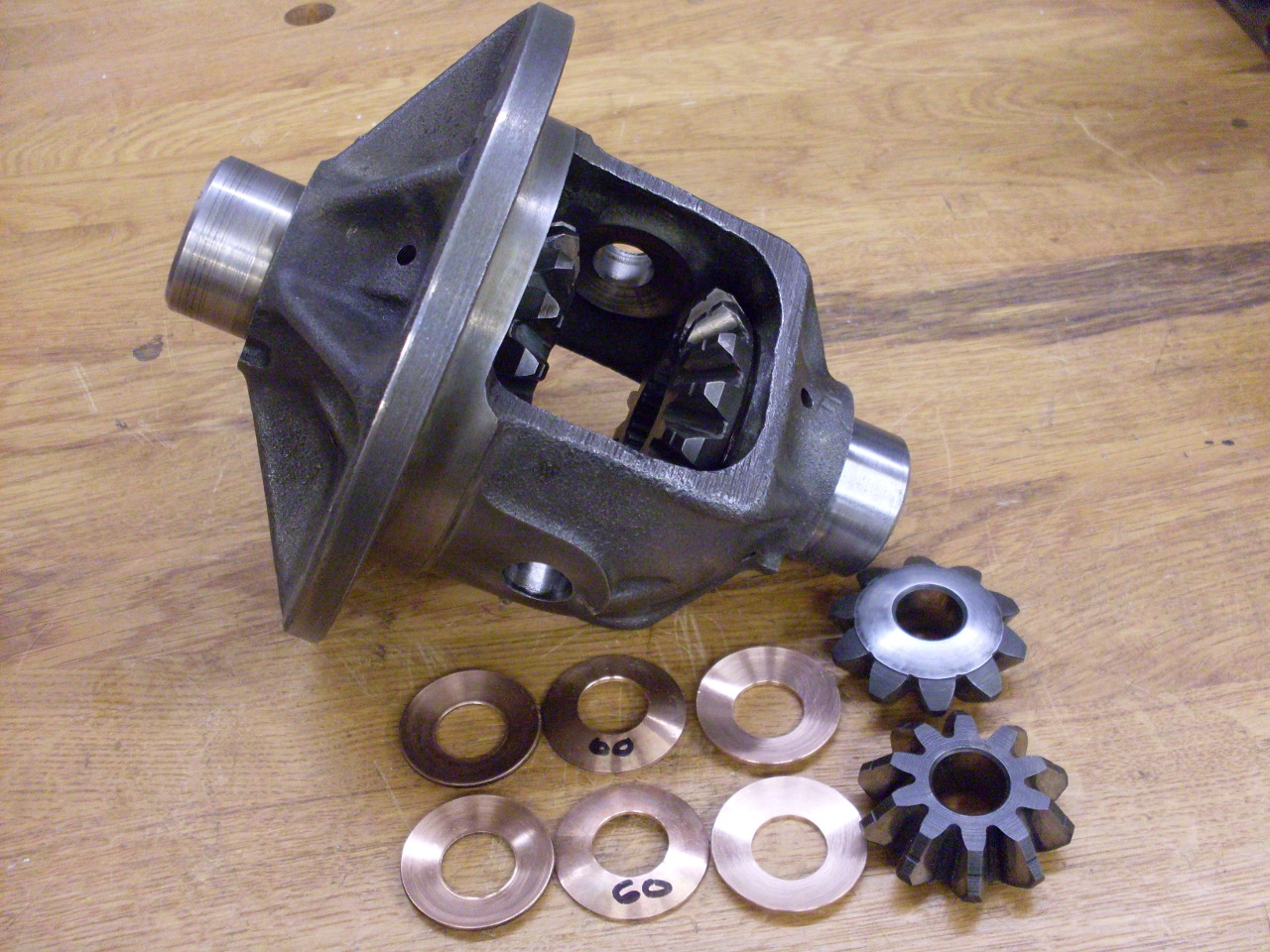
I
first tried installing a pair of new 0.060" washers--the same as I
found in the unit--on the theory that most of the wear would
have been in
the washers. This didn't seem to change the backlash very
much,
so I then tried a pair of 0.062" washers. This resulted in no
detectable backlash. The gears were slightly stiff, but with
good
lubrication and a few miles, I expect they will loosen up.
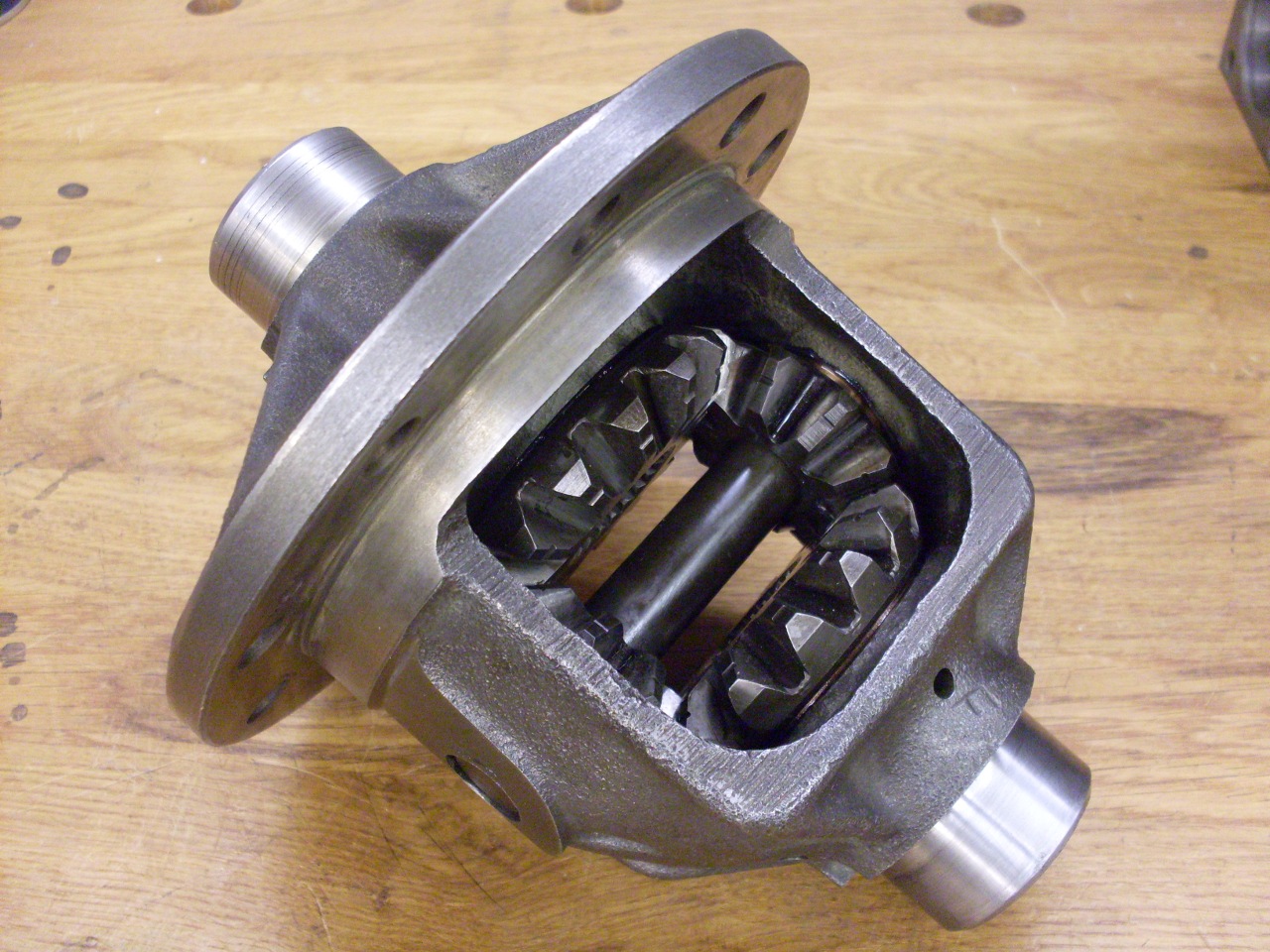
So here is the
differential carrier all back together (except for the crown wheel,
which has to come later).
Two
more critical specs in the differential are the preload of the
differential carrier bearings, and the side-to-side position of the
crown wheel. There is a shim pack under each differential
carrier
bearing cone. The total thickness of these shims determines
the
preload, while the distribution of them (some on the right, the rest on
the left) changes the crown wheel position. The process for
determining the size and distribution of the shims seems complex at
first, but it is entirely straightforward and logical.
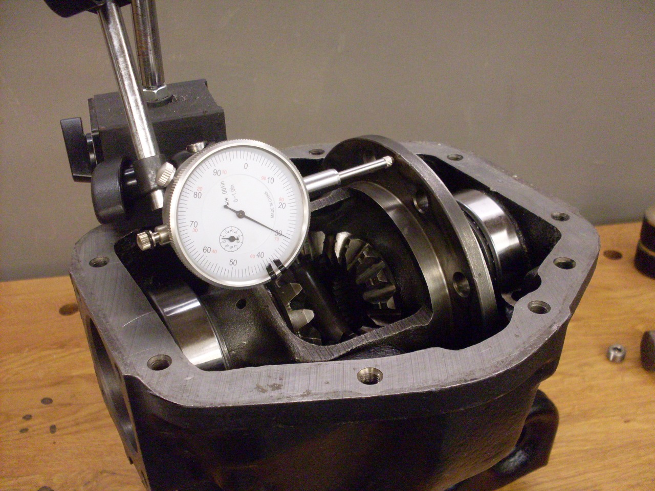
First, the differential
carrier bearing cones are mounted without any shims.
The
carrier is then set into the case, and the end float measured.
This measurement is how much wider the case is than the
carrier
with bearings. To this measurement, we add 0.003" for
preload.
The total is the thickness of shims that will increase the
width
of the carrier (including bearings) to 0.003" wider than the case.
I
actually found it a little easier and more repeatable to measure the
float with loose feeler guages behind one of the carrier outer races
(second pic). In my case, the end float was 0.045", so the
total
preload shim pack would need to be 0.048".
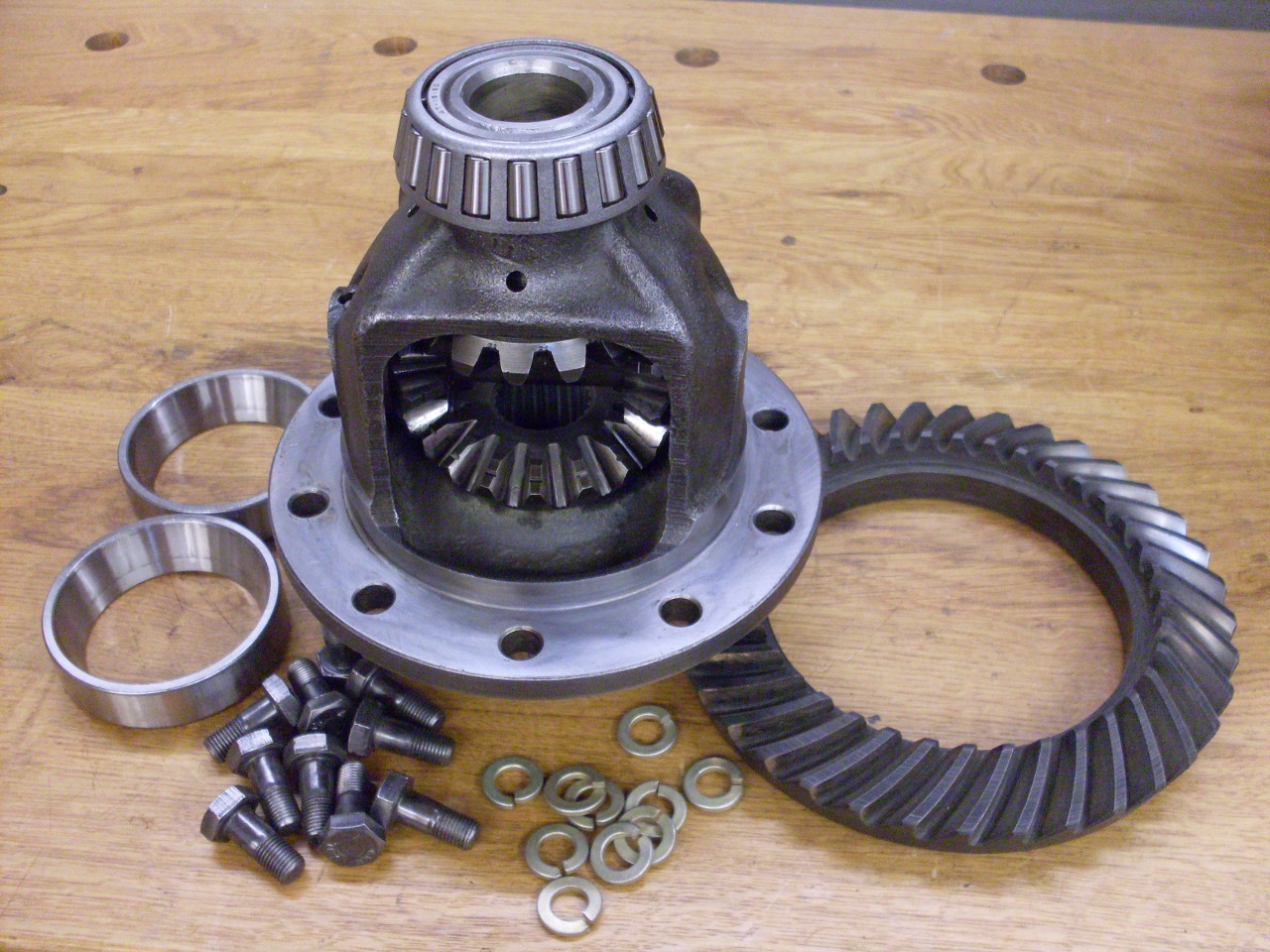
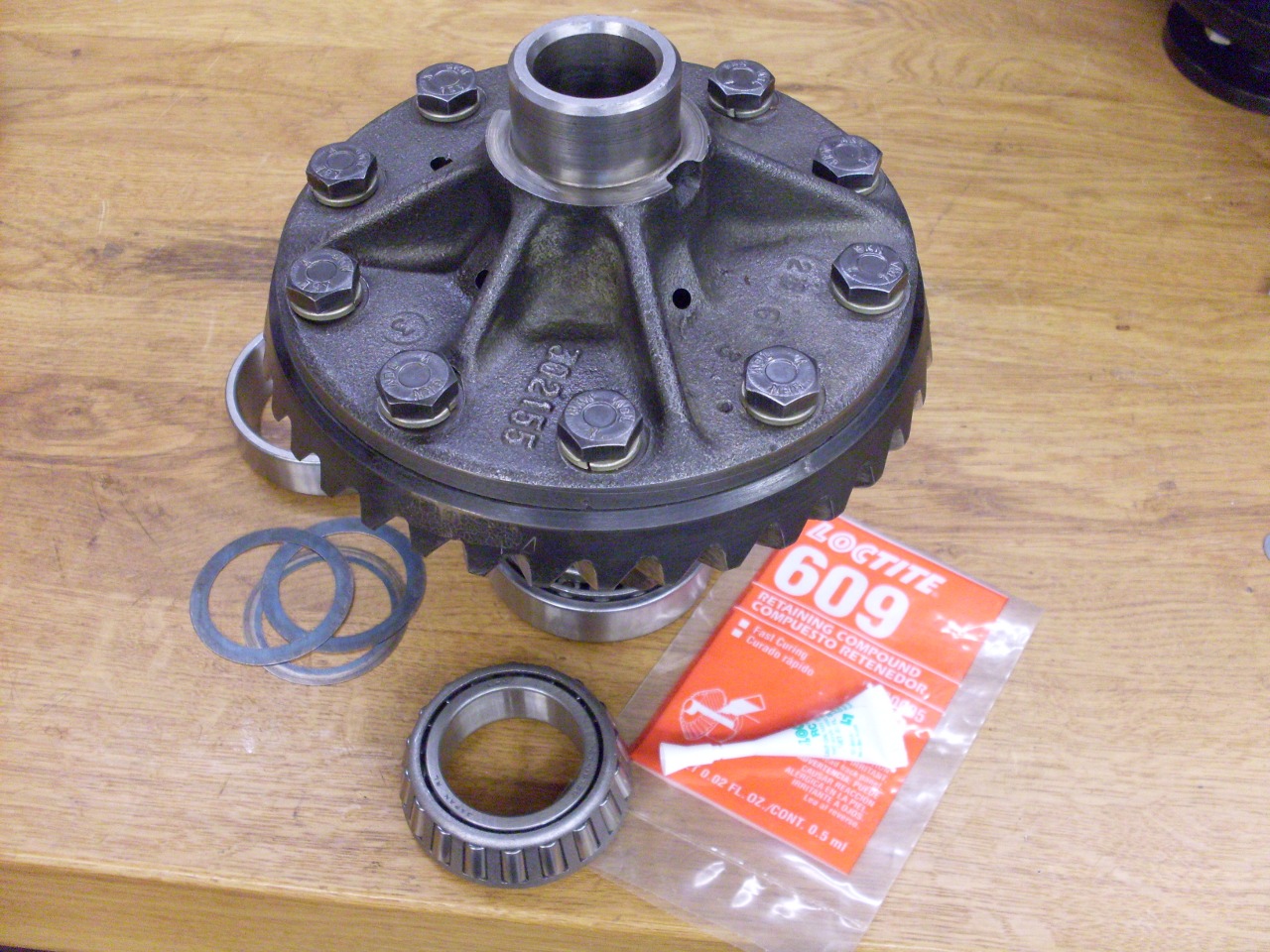
Then
it was time to mount the crown wheel back in its previously marked
position on the carrier. The crown wheel fasteners are grade
"T"
(close to SAE Grade 8), so it's not a place to use hardware store
screws. I used new grade 8 lock washers, and Locktite, per
the
manual.
The
carrier with crown wheel is then placed back in the case without preload shims, and the end
float measured again. This time, since the pinion gear will
now
limit the movement of the carrier in one direction, the measurement
represents the
difference between zero and maximum clearance between the crown wheel
and the pinion gear. Subtracting 0.005" from this measurement
gives the shim thickness that would give a crown wheel-pinion
clearance of 0.005". This is the shim pack that goes inder
the
bearing cone on the crown wheel side. The remainder of the
total
preload shim thickness then goes on the other side. In my
case,
of the 0.048" preload shim pack thickness, 0.030" went on the crown
wheel side, and 0.018" went on the other side.
The bearing cones
had to come back off to install the shims. One of the carrier
bearings got fairly loose on its journal, so I helped it out by adding
some bearing mount compound.
Then
the case spreader was mounted again to open the case enough to alow the
carrier to drop in. The bearing caps were installed and torqued,
and the final backlash measured. I saw with a sigh of relief
that
my backlash was 0.004" and compliant with the spec.
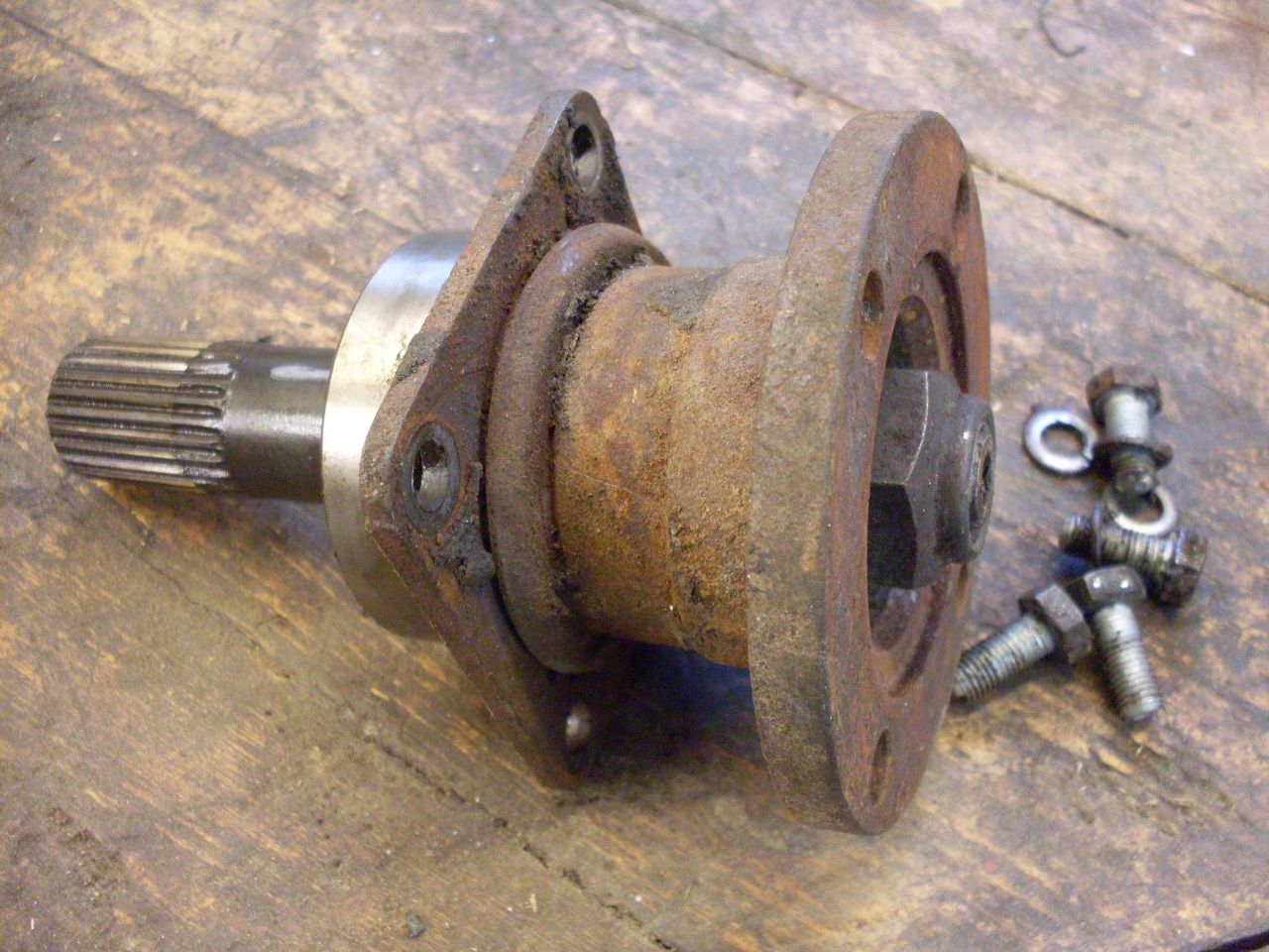
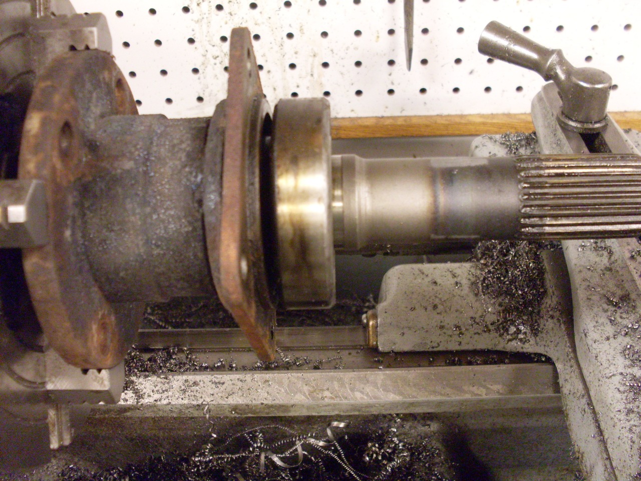
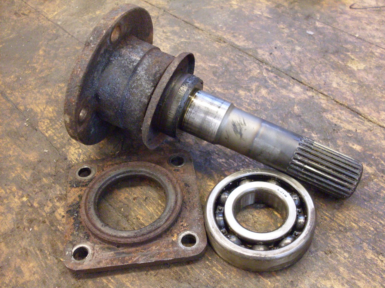
The last major part of the differential unit was the inner axles.
These axles deliver power to the external flanges that the
rear half axles attach to. The inner axles consist of short
splined shafts that each carry a ball bearing and an external flange.
The flange is mounted on a taper on the outer end of the
shaft, and it has to be removed to withdraw the bearing and oil seal.
This is where the trouble started.
Now, I'm not a novice at dislodging things that are pressed on, or
wedged on, such as with a taper. I have a decent hydraulic
press and the wherewithall to create a wide range of implements of
seperation. I tried the press first, and got it to the point
where it was creaking ominously. I then added heat to the
mix. The axle mocked me.
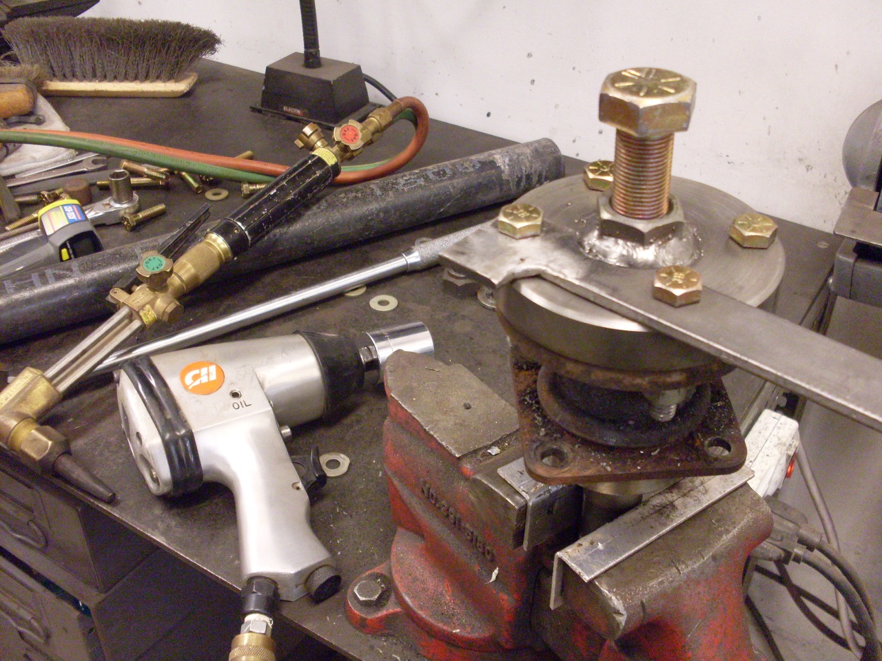
Not to be bested by an intert lump of steel, I made a custom puller
whose grade 8 hardware would be able to apply as much pressure as my
press, but with the added pursuading power of an impact driver.

After several intense cycles of pressure, heat, impact, and
swearing, the axle remained aloof. I was pushing the system
to the point where I was concerned about damaging the axle flange.
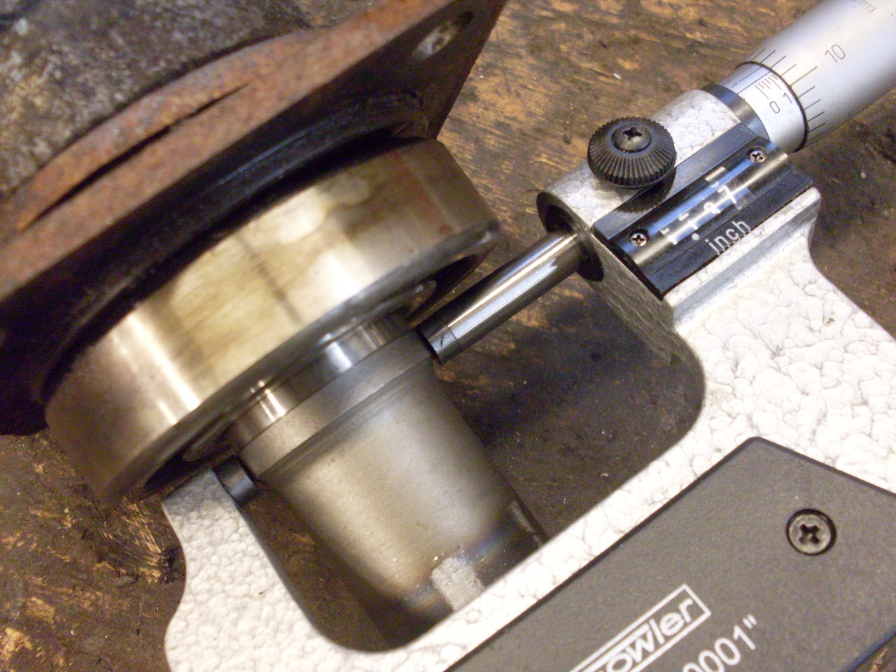
As I paused to catch my breath and assess the situation, my more
analytical self began to consider whether there may be a smarter, less
brutish way to solve the problem. The bearing on both axles
was mounted up against the hub, but the machined 1-1/8" bearing journal
extended about 1/8" beyond the bearing to a shallow shoulder.
The shoulder was only about 0.006" high and 1/8" wide, and
was the only thing standing between that bearing and sweet liberation.
Now I don't have much doubt that, given enough acetylene and
violence, I would have eventually triumphed over those hubs, but
on the other hand, the prospect of pulling the bearings off from the
other direction began to look much more civilized. It was
just that little wisp of metal to deal with, and removing it
would be trivial. I considered the shoulder and whether it
was there intentionally for some purpose. It certainly wasn't
a locating shoulder, since the bearing was an eighth of an inch away from it.
Possibly it was a retaining shoulder, to prevent the axle
from creeping out of the bearing. Neither bearing showed any
evidence of creeping, and further, it seems that if that were its
purpose, it would have been closer to the bearing and a little more
prominent than 0.006".
In the end, I decided to do away with the shoulder and think later
about replacing its function, if any.
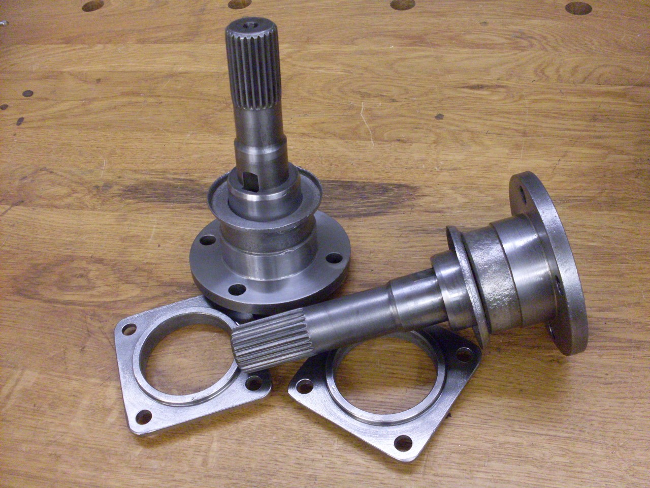
Ten minutes to turn off the shoulder, ten minutes to set up the press,
and the bearing was off. I now consider the axle and hub to
be one piece.
Then a pleasant degrease and derust, and a nice powder coat.
Now,
about the late shoulder. The only earthly purpose I can imagine
for it is that it would keep the shaft from pulling out of the bearing.
Even though it appeared unlikely that this would happen, it
seemed prudent to restore that function, even if it wasn't intended in
the original design. I decided to fashion a collar to go next to
the bearing to stand in for the missing shoulder.
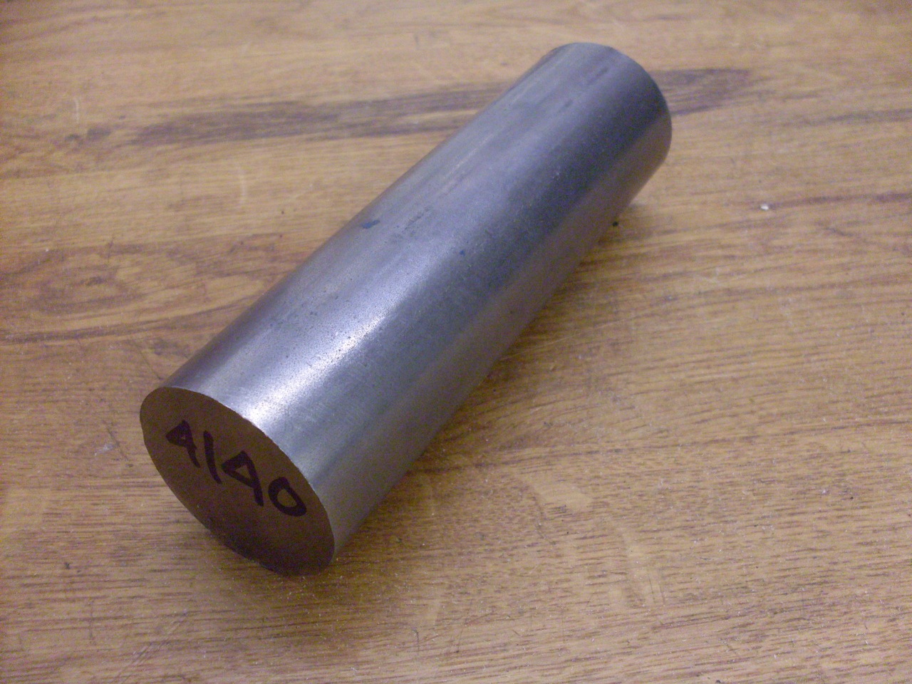
I started out with a hunk of really good steel...
...and turned a couple of rings with the same ID as the bearings.
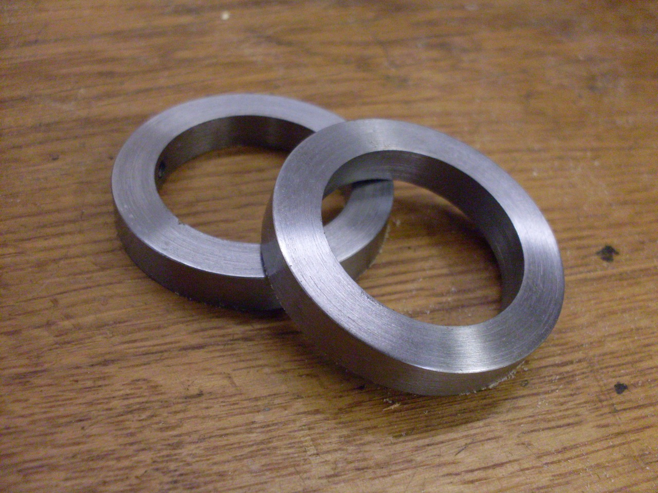
Then
drilled and tapped three holes in each one for set screws. The
set screws are the kind that have a little nose on the end that goes
into matching holes in the shaft.

Pressed the seals into their carriers.
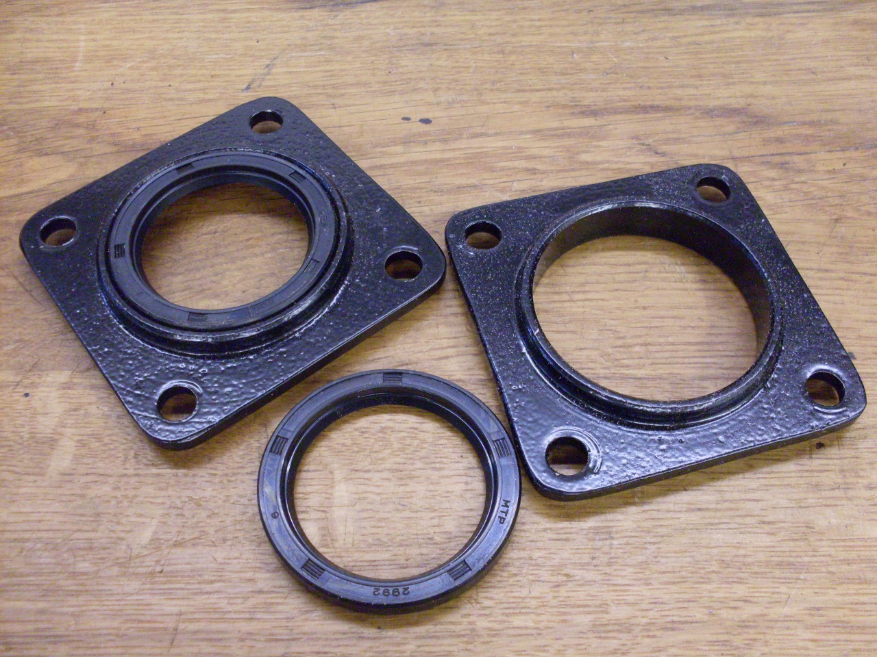
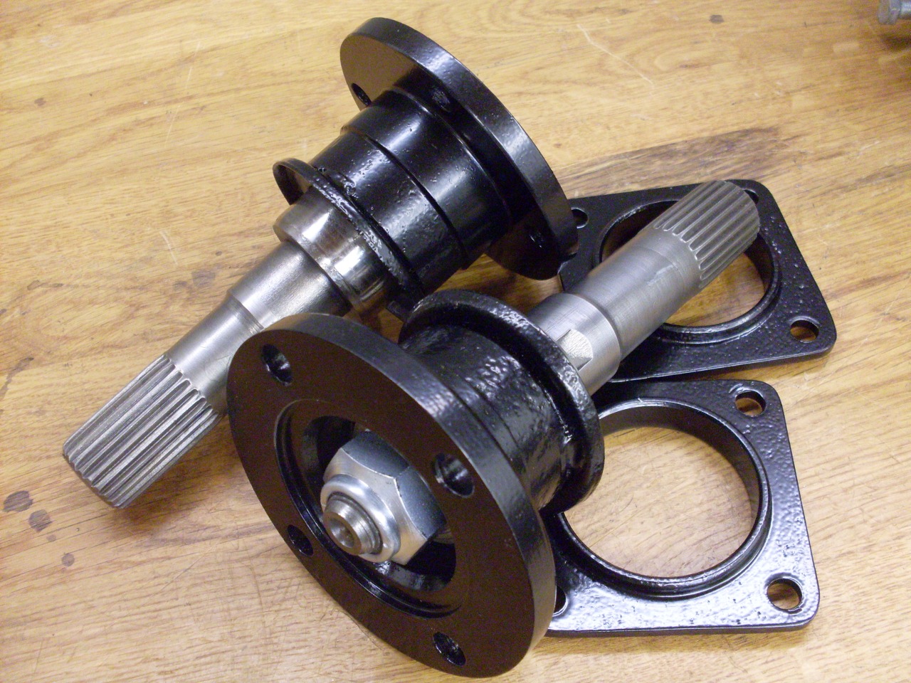
Here are all the parts for the inner axles.

Pushed on the bearings with that little pipe thingy, and installed the collars with a little Locktite on the setscrews.
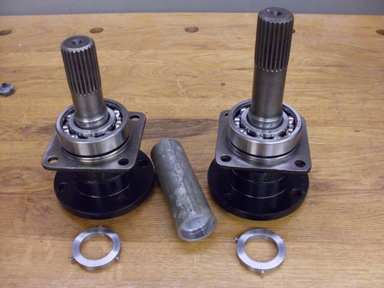

Shoved
in the axles and tightened down the seal flange. The flanges
don't have gaskets, but some sealer seemed like a good idea, so I broke
out my trusty Permatex 3D. I considered making some gaskets, but
the flange also captures the bearing's outer race, which is otherwise a
fairly loose fit in the case. A gasket might give the race enough
room to shift a little, or even turn. Also installed stainless fill and drain plugs.

Rounded up all the replated fasteners for the rear cover, using new lockwashers. A couple of dowels locate the cover.
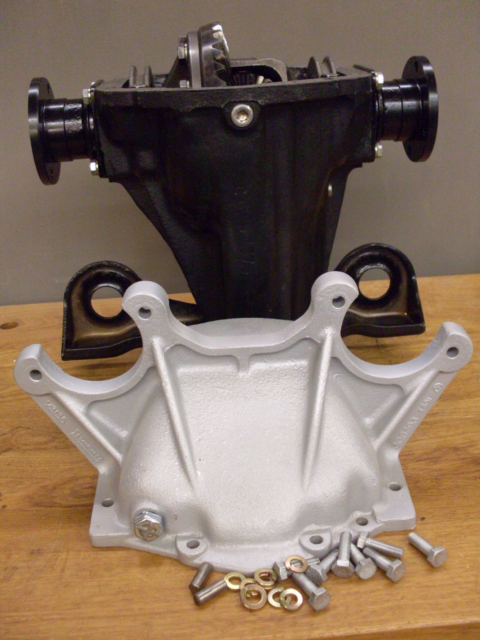
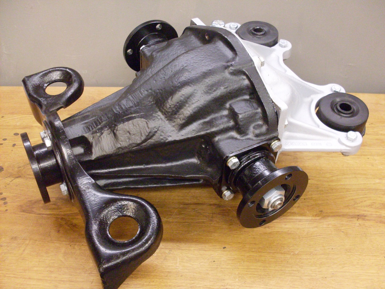
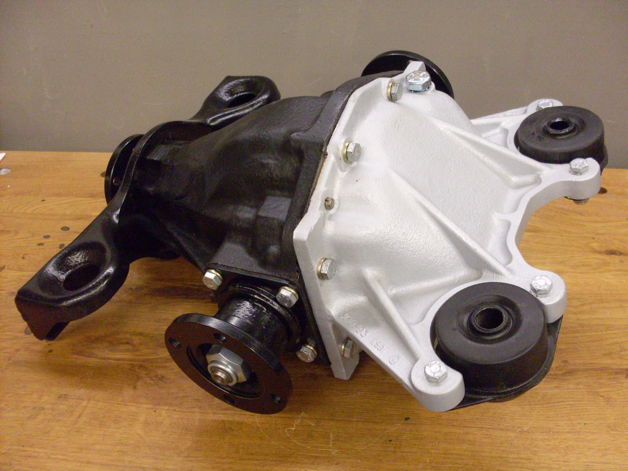
Buttoned
up the cover, and added new mounts to it. This puppy goes on the
shelf to make some bench space for something else.
So
was the creativity with the axle shafts a good idea? I don't know
yet, but for the time being, it keeps me from admitting that the axle
shafts beat me.
Send comments to:
elhollin1@yahoo.com
To Other TR6
Pages