To my other GT6 pages
November 28, 2019
Starter
My
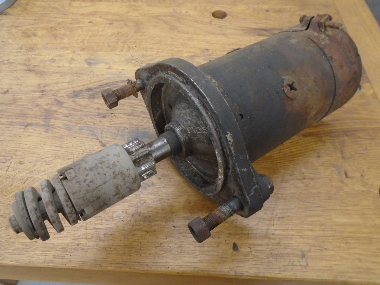
GT6 had a Lucas M35G starter motor. This is a ubiquitous motor,
found on a range of British cars dating back at least into the 1950s.
It was fitted with an inertial "Bendix" drive mechanism for
engaging with the flywheel's ring gear. My starter was pretty
crusty, but as far as I knew, it worked.
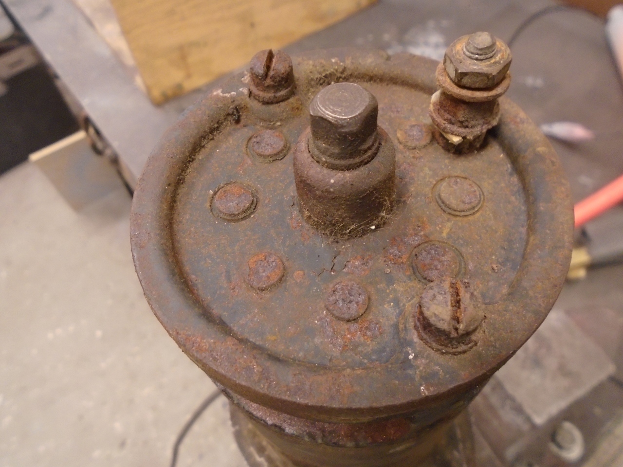
Really,
the only difficulty I had in taking the unit apart was with the
electrical connecting stud. The lower nut on the stud has to be
removed in order to get the end plate off, but it seemed to be seized
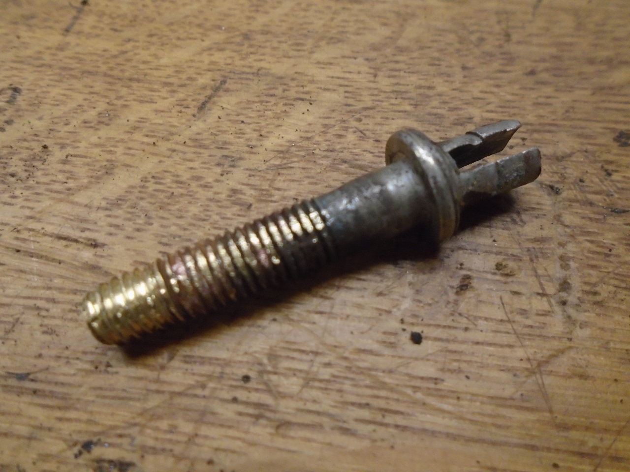
on the stud. The stud was turning, which didn't seem to be a good
thing. I resorted to cutting the nut off, and when the cap
finally was removed, I saw the result of the spinning stud. That
flat on the stud is supposed to keep it from turning, but it didn't.
So I could then pull the armature from the main body.
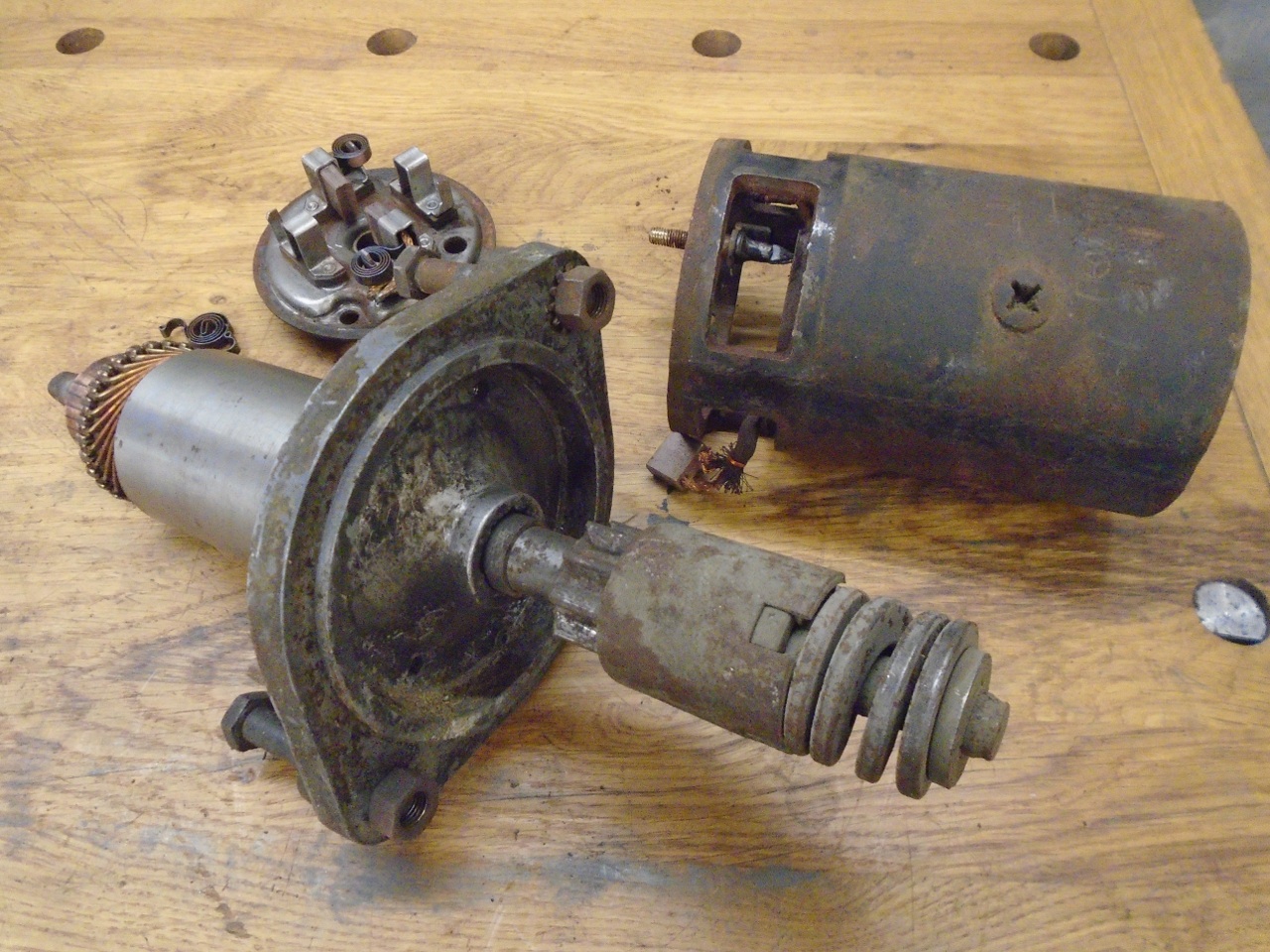
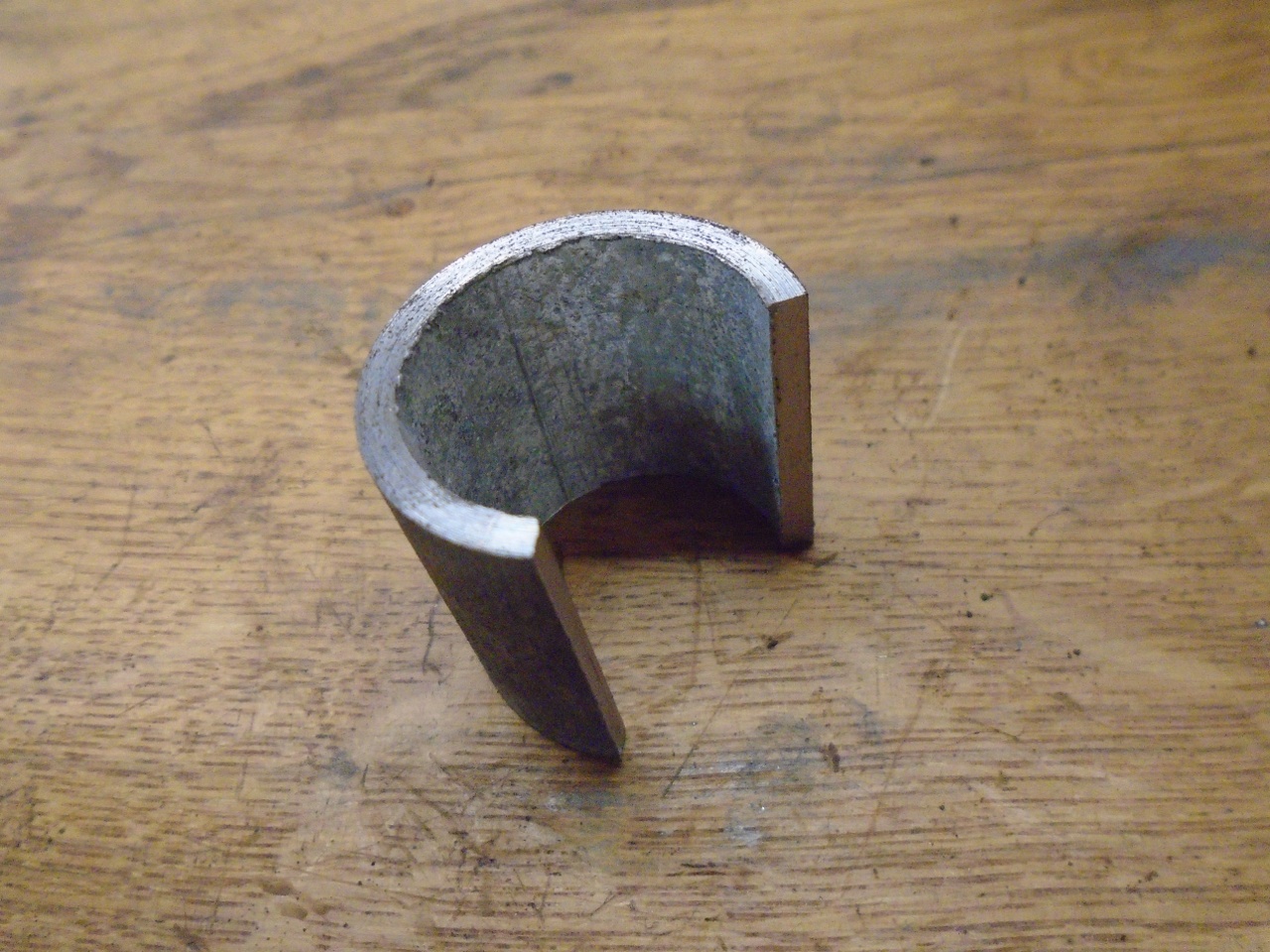
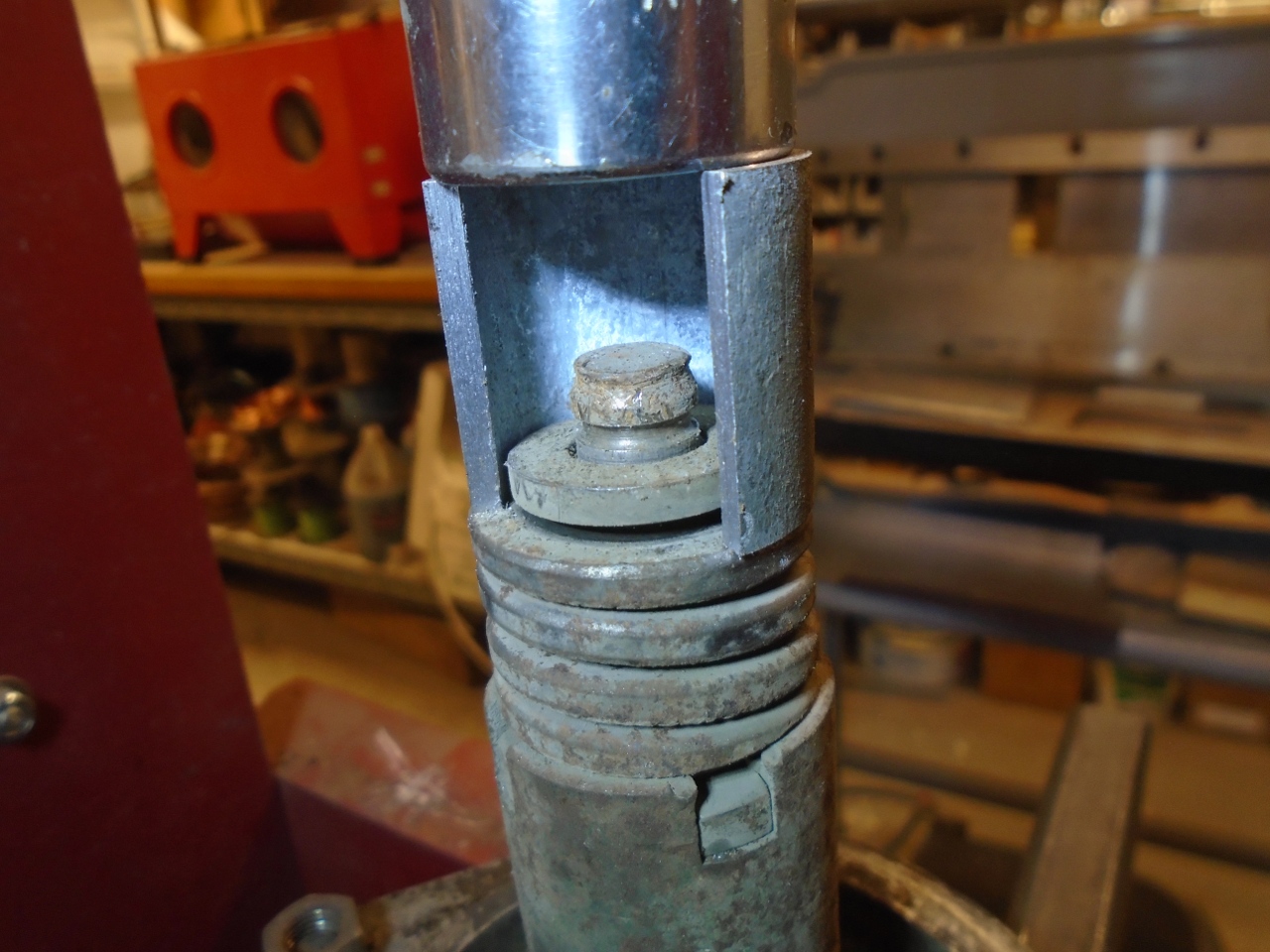
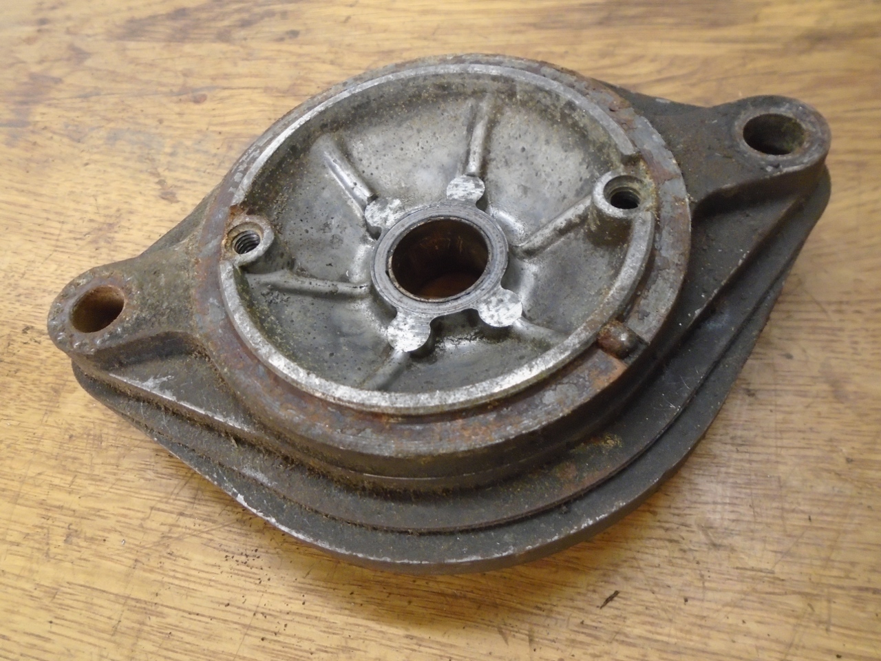
To
get the other end cap off, the Bendix parts have to be removed.
This little section of pipe with an arc cut out allows access on
the press to remove the little snap ring.
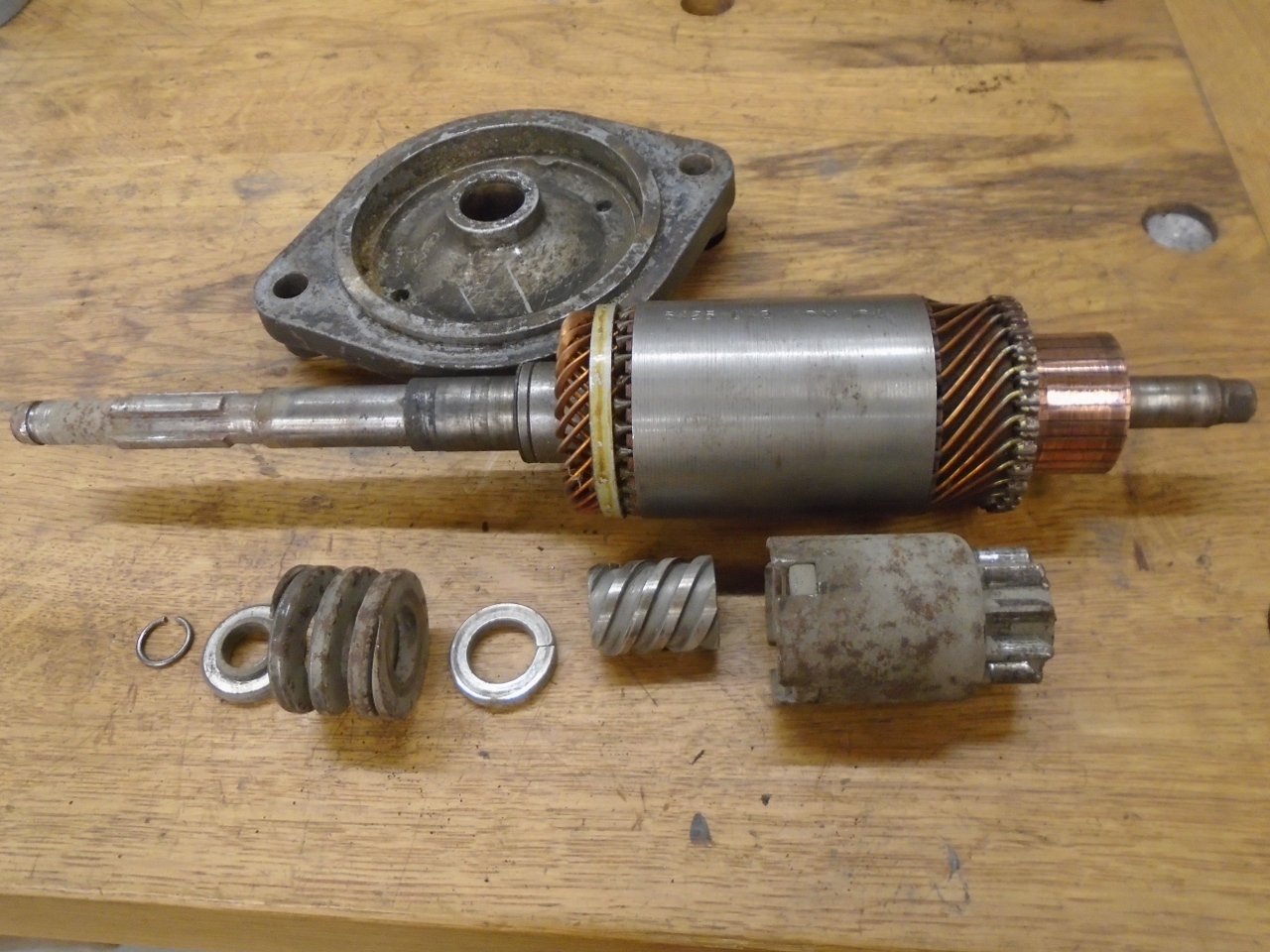
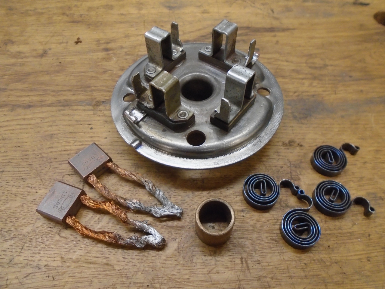
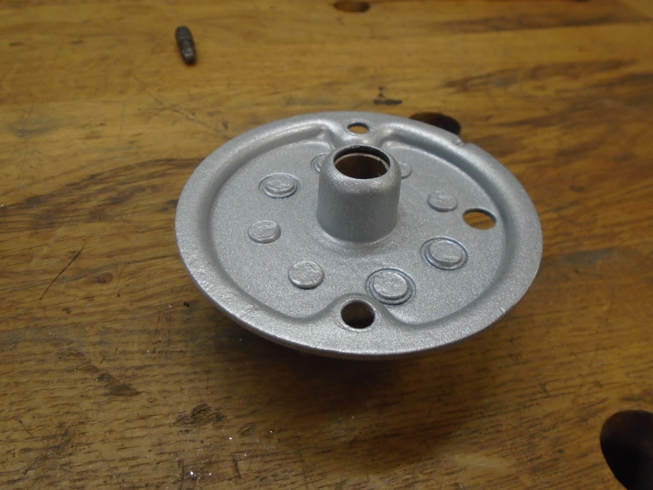
Each of the end caps has an sintered, oil impregnated bushing.
Now,
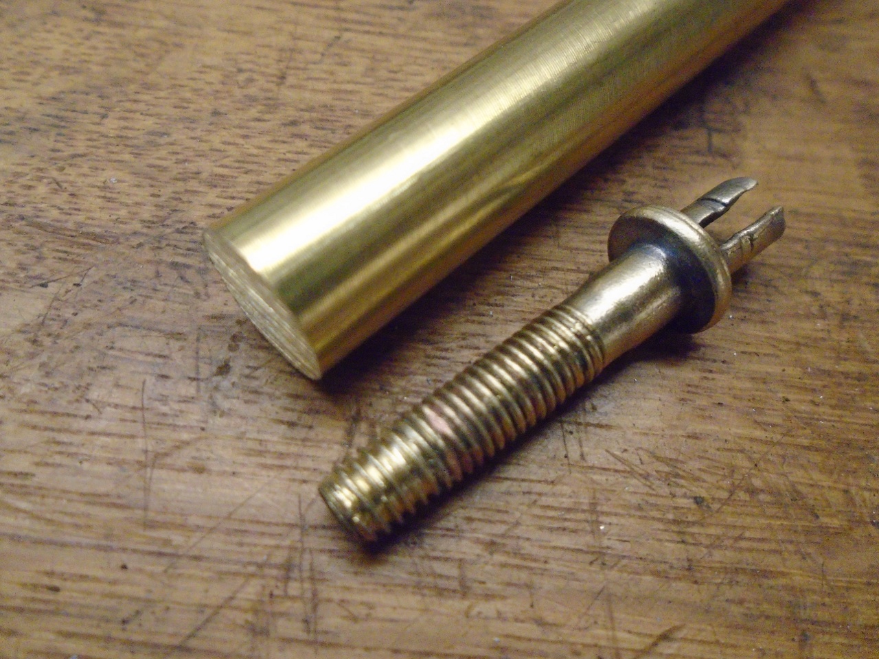
back to that troublesome electrical stud. The threads on it were
pretty beat up. In fact, they were so bad that when I measured
them so I could chase them with a die, I thought they were M6-1.
Well, they weren't, they were 1/4-28, and the M6-1 die just made
it worse. Finally, I just unsoldered the stud from the flat field
conductors.
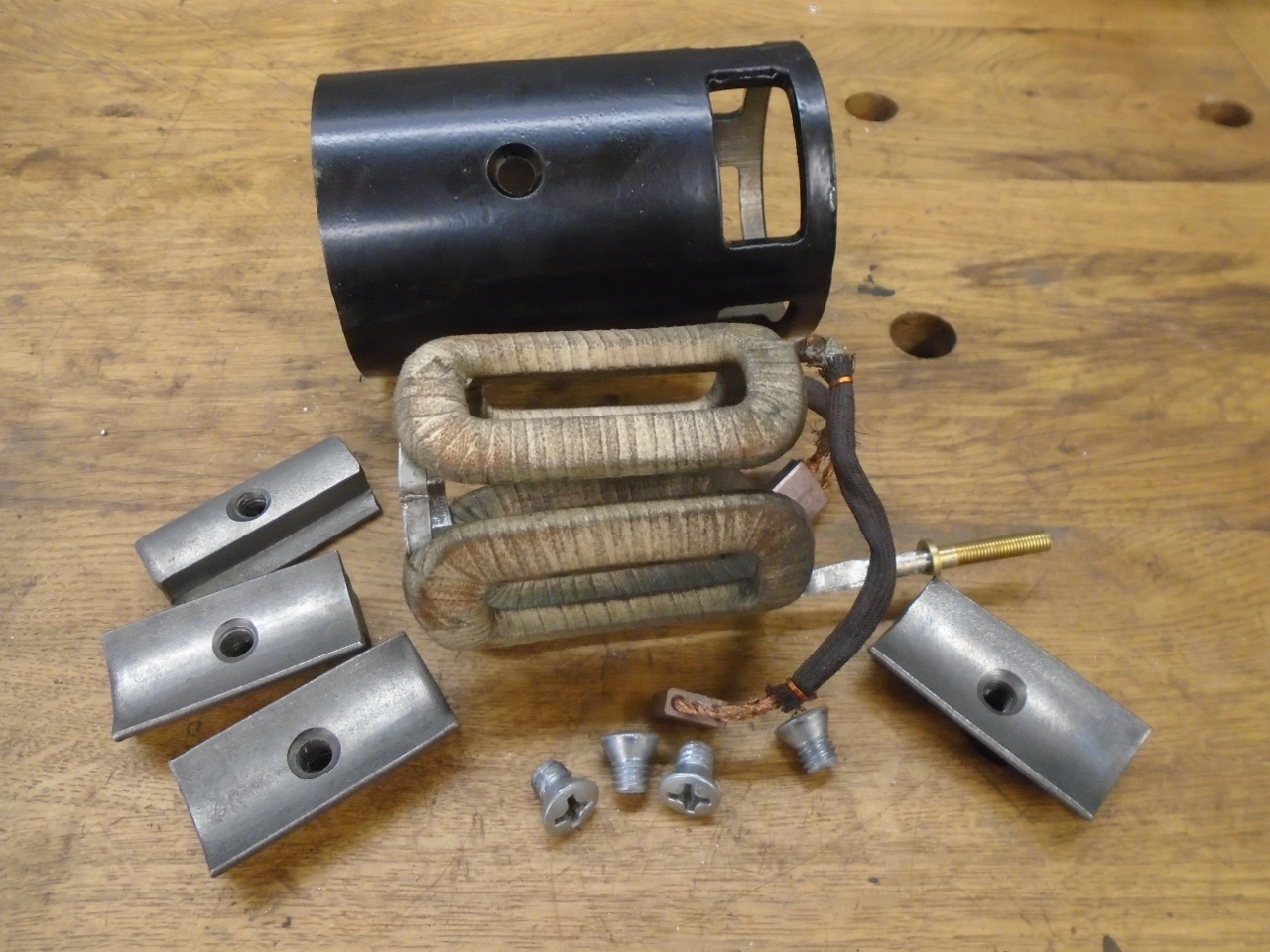
"Why
stop there?" I asked as I proceeded to remove the field windings.
The windings are held in place by iron pole pieces, which are in
turn attached to the body by big oval head screws.
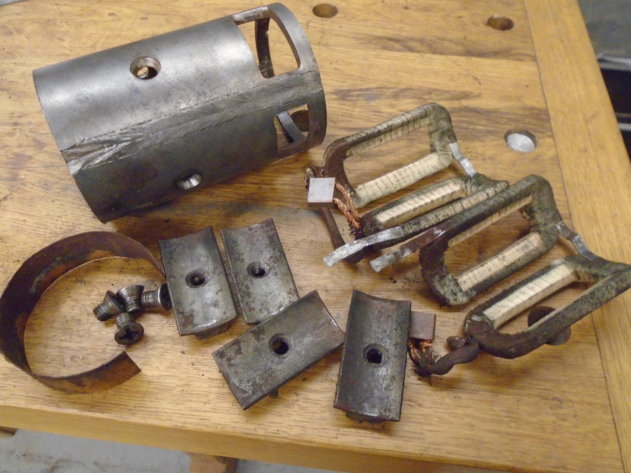
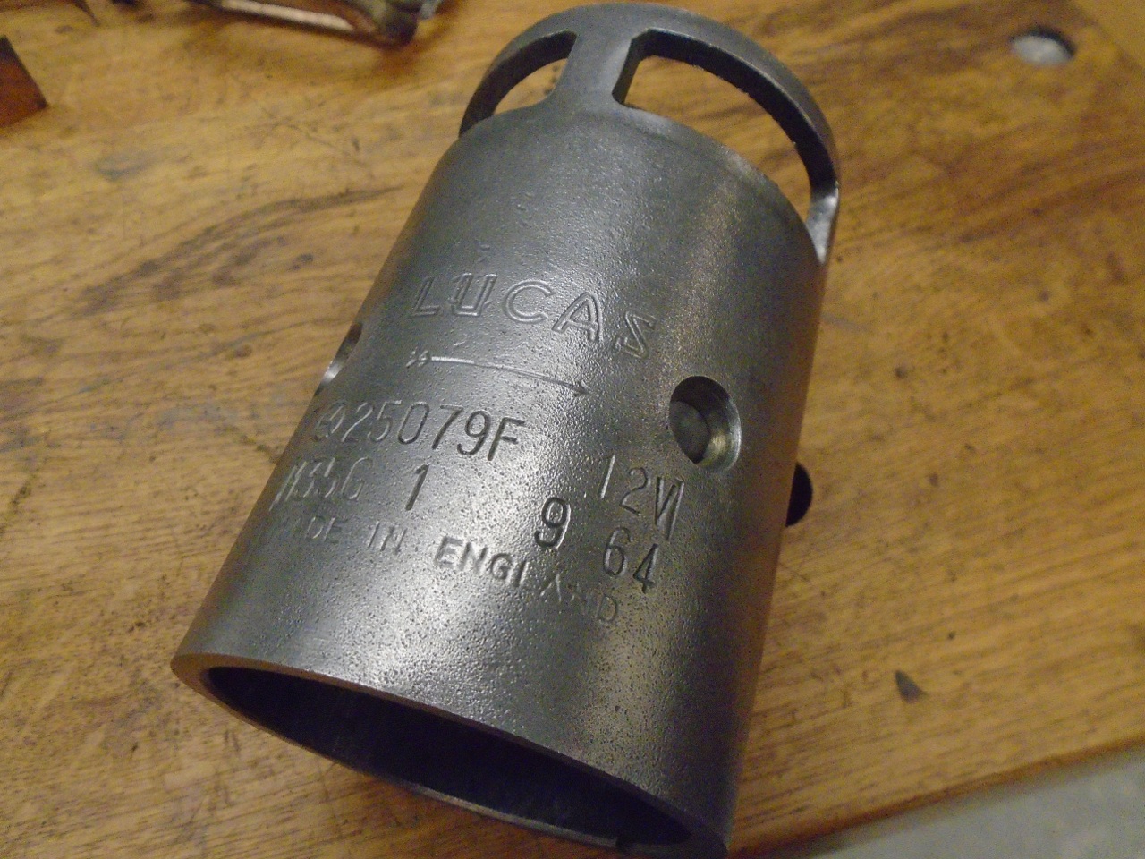
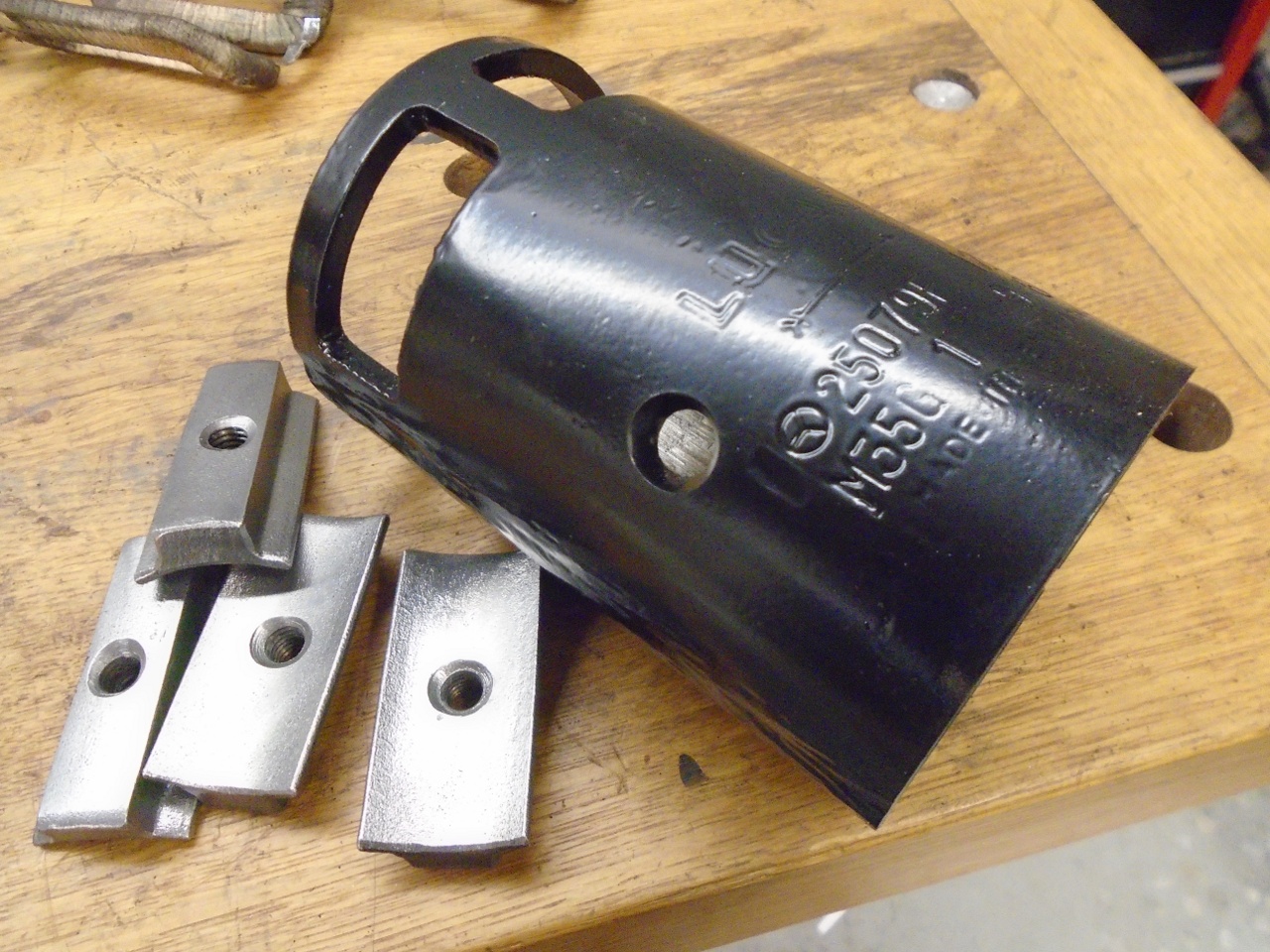
Taking
out the field windings made cleanup much easier, and also allowed me to
powder coat the main barrel. I'm not sure the field winding
insulation could have taken the heat. I noticed that the starter
had a date code of 9 64, implying that it was probably a rebuilt
replacement.
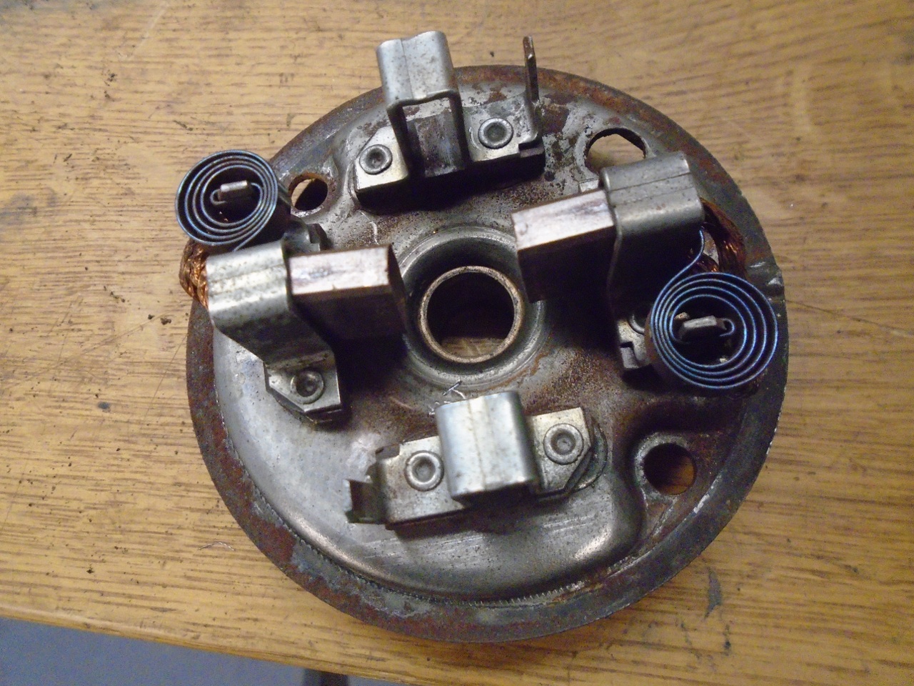
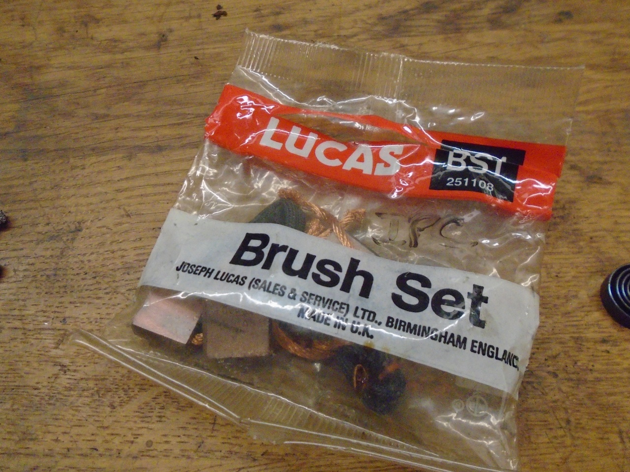
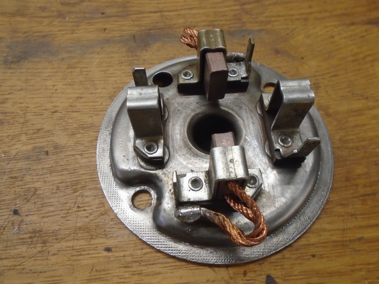
The
brushes all appeared to be OK for length, but the wire leads on the
ground bushes in the end cap were very stiff with solder. This
can happen when replacing them if the heat is left on too long, and
solder wicks it the braided lead. I removed the ground brushes
and replaced them, but left the other two brushes as they were.
It takes quite a bit of heat to solder on a part with this much
metal. The biggest soldering gun I have is 300 watts, but I have
two of them, and it took them both.
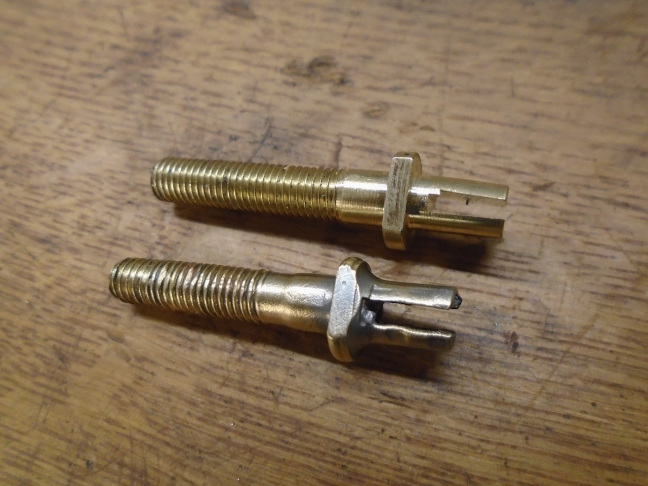
Back to the stud once more. I didn't see a good way to salvage it, so I made a new one.
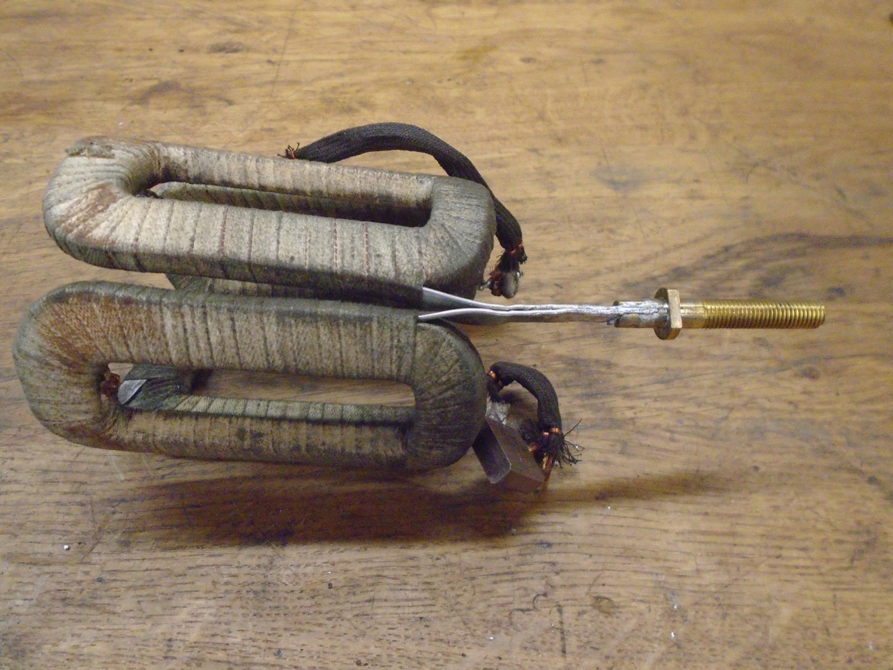
Then
strapped the field coils together around a dummy core to attach the new
stud. I had a hell of a time getting the solder to flow well. I
struggled with it for a time until It dawned on me that the field
windings, which I had assumed were tinned copper, were actually
aluminum! In hindsight, I the light weight of the coils should
have been a clue, but I missed it. I ordered some special solder
that will bond aluminum and brass, and that worked fine.
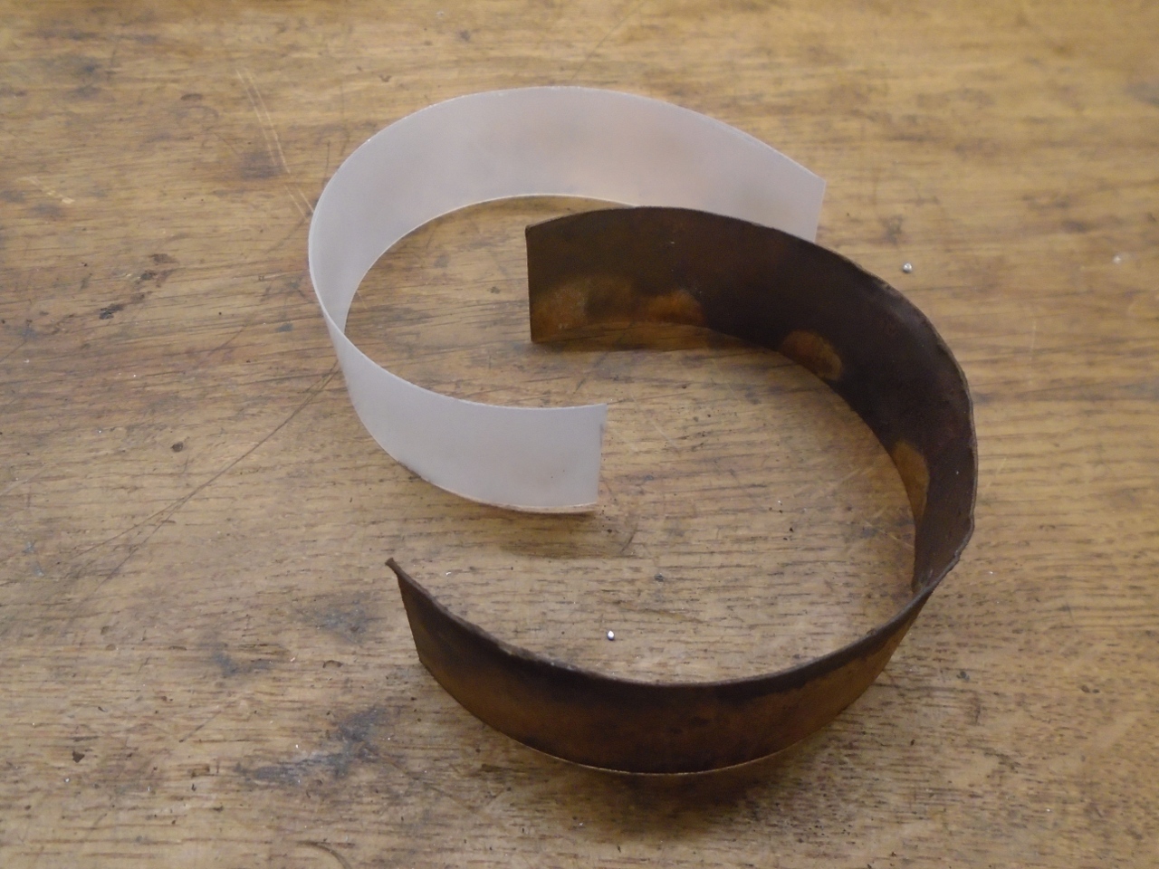
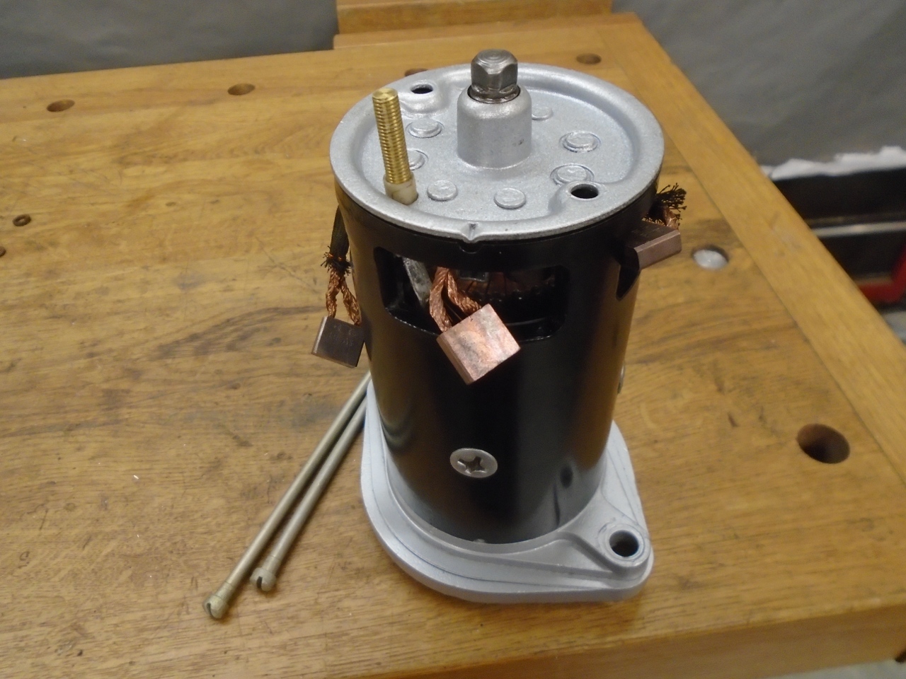
So
then the main body was ready to go back together. Originally,
there was a paper insulator that went around the inside of the
barrel near where some of the bare connections are.
It seemed a little frail, so I replaced it with a like-sized
piece of sheet nylon.
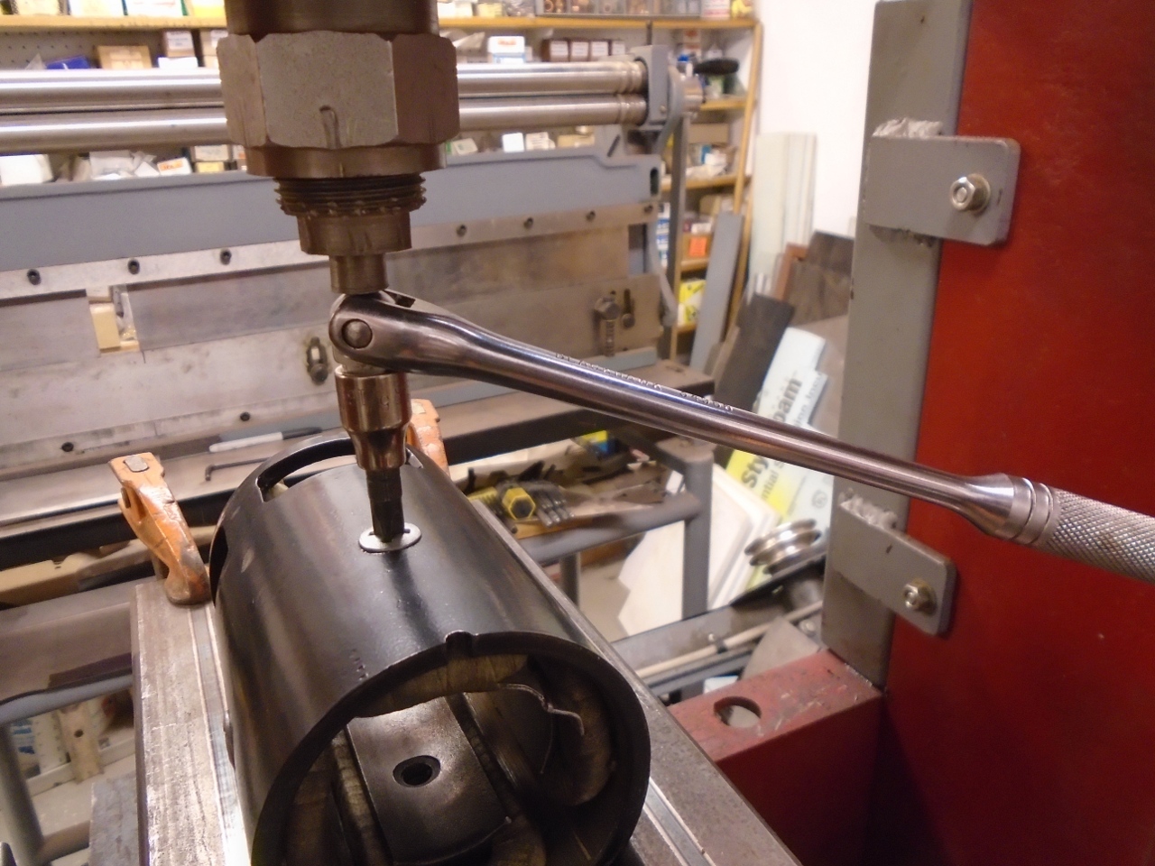
To
tighten the screws holding the pole pieces, shops have a special tool
that presses a large phillips bit down while it is turned. My
makeshift version worked well for both disassembly and assembly.
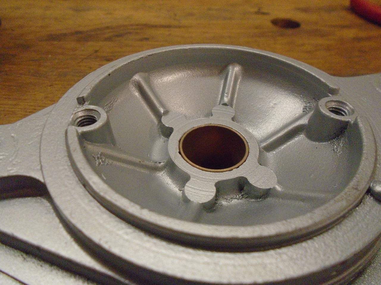
New Oilite bushes in the end caps. One side note here. On
the driving end cap, some powder coat got into the threads for the long
screws. "No problem", I said, reaching for the 1/4-28 tap to
clean them out. The tap didn't seem to want to start.
Before I forced anything, on a hunch, I grabbed one of the long
screws that hold the caps to the body, and checked the thread pitch.
Sure enough, it was a rather unusual 1/4-26, known to the Brits
as BSC threads Those Brits sure do like theuir odd ball threads.
In a stroke of luck, I actually had a 1/4-26 tap that I bought
when working on my British motoryucle.
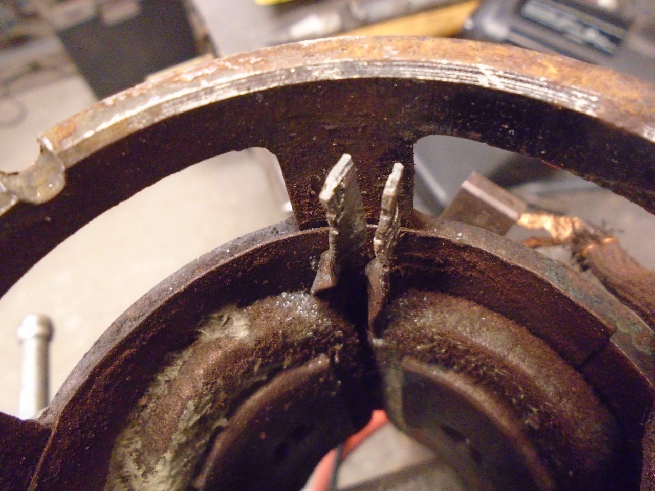
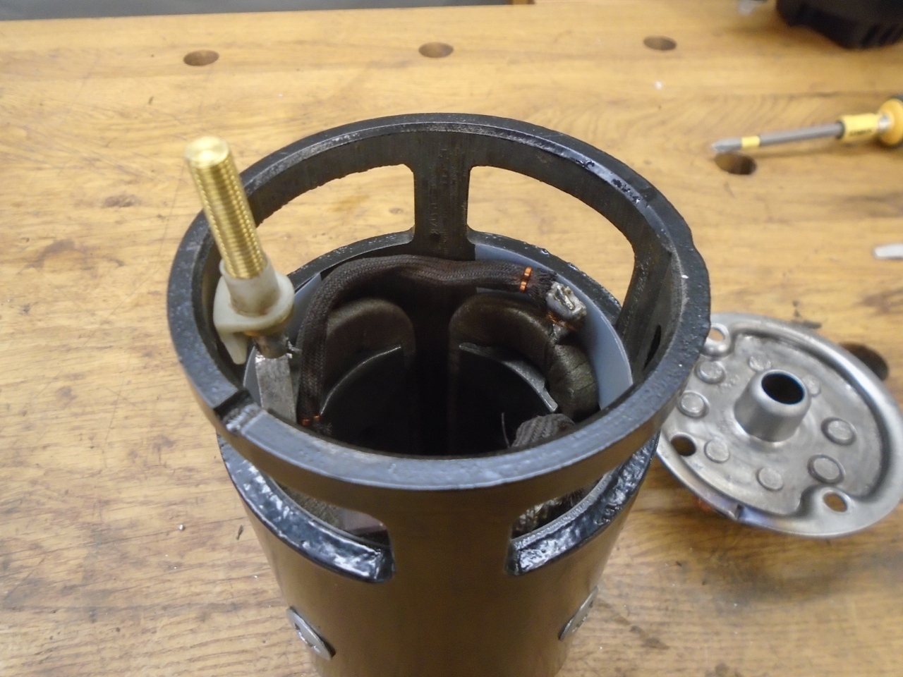
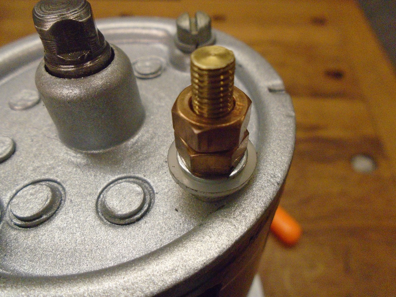
To get the electrical end cap on, the field leads had to be spread a little to lower the stud.
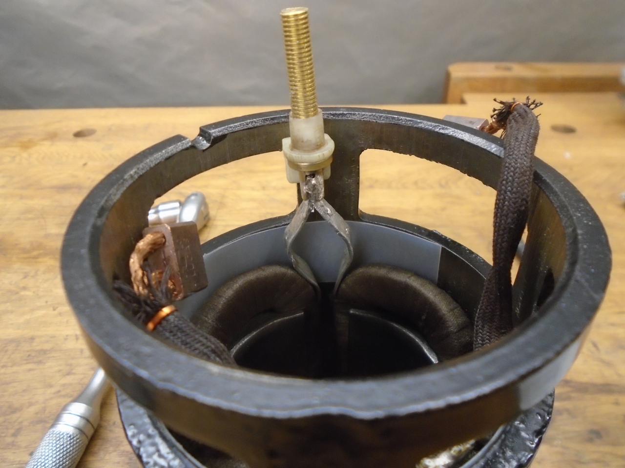
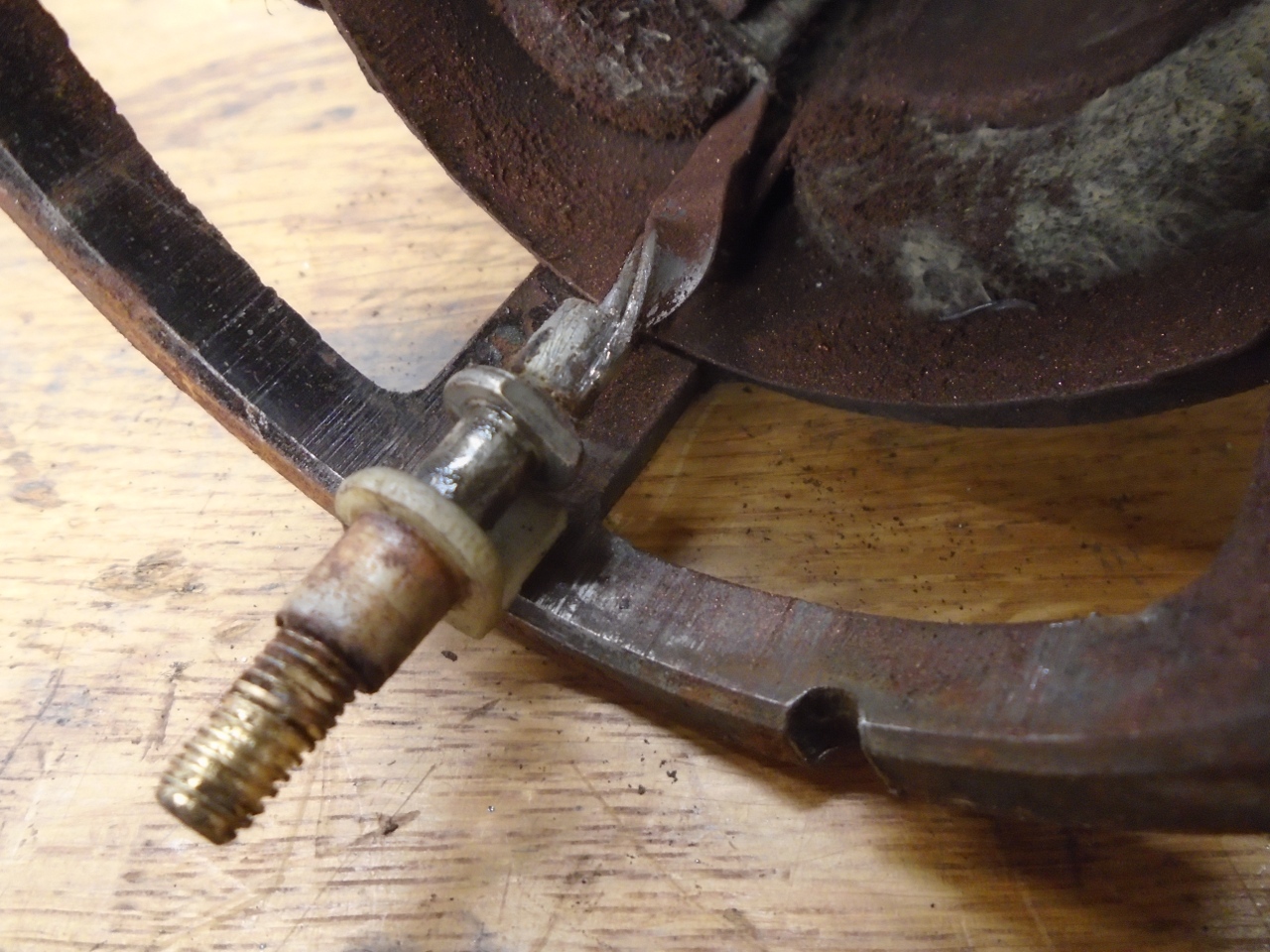
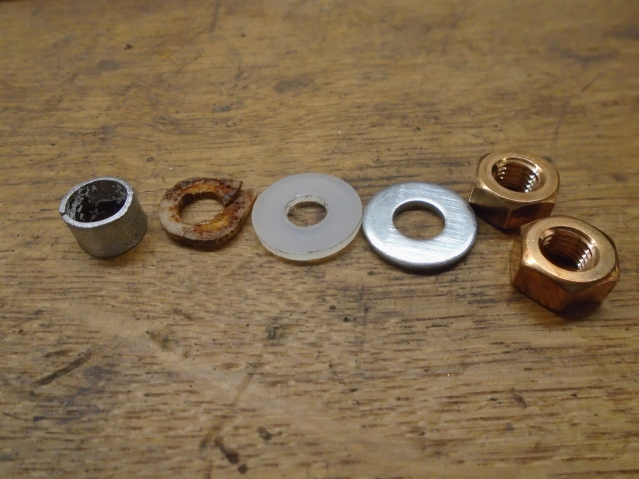
The
electrical stud of course has to be carefully insulated from the body
of the starter. There is a plastic sleeve that comes up through
the end cap (seen above), then a metal sleeve goes over that to take
the thrust force of the nut, then an insulating washer (the original
fiber one and my nylon one shown below), then a steel washer , then the
stud retaining nut, then the cable retaining nut.
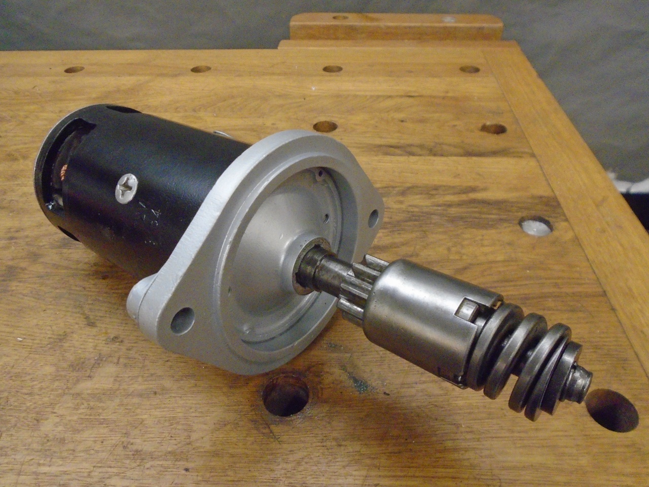
Then
replaced the cleaned up Bendix parts. Putting grease in it didn't
seem right, so I just sprinkled some graphite powder on the parts
before assembly.
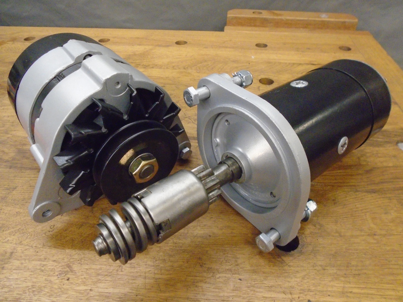
So here is the recently done alternator
and the starter ("The Twins"). They sort of do opposite things.
They go on the shelf, waiting for install one bright day.
This
was an enjoyable project, with some things I hadn't done before.
Cost was small--less than $25 for bushes, brushes, some hardware,
and a hunk of brass.
Comments to Ed at elhollin1@yahoo.com
To my other GT6 pages