To my other GT6 pages.
November 21, 2019
Gearbox
[All the pics are clickable]
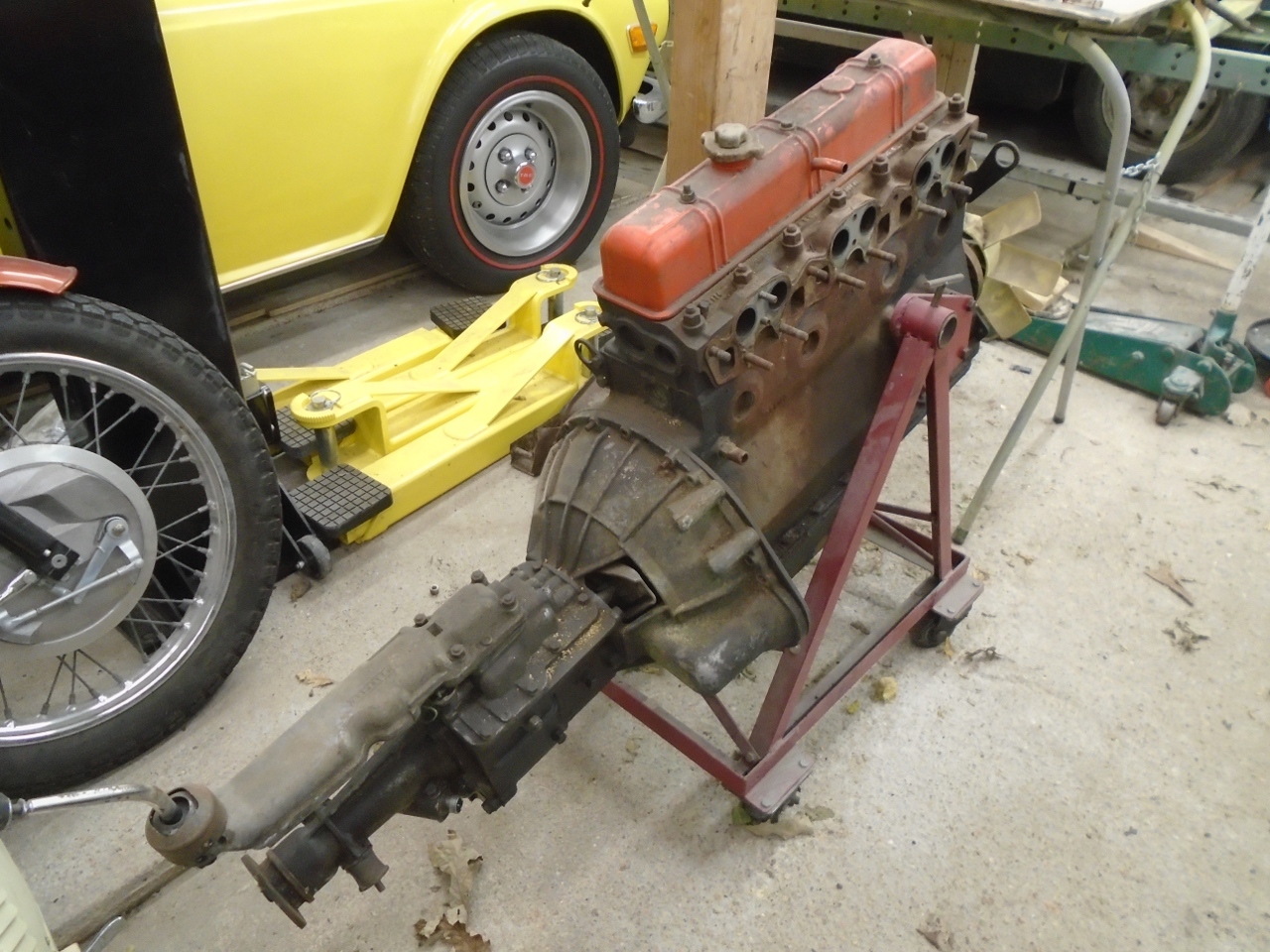
The gearbox in my GT6 was a pretty ordinary non-overdrive four speed unit with synchromesh in all four gears.
First
job was to divorce the box from the engine and get it down to the shop.
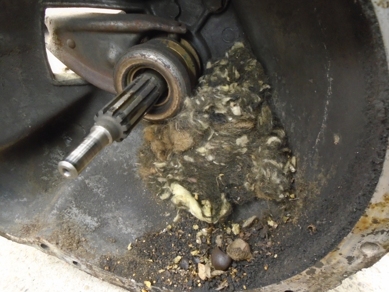
There was an abandoned critter household in the bell housing.
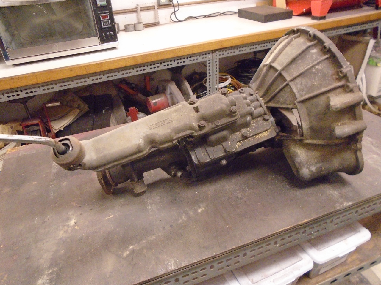
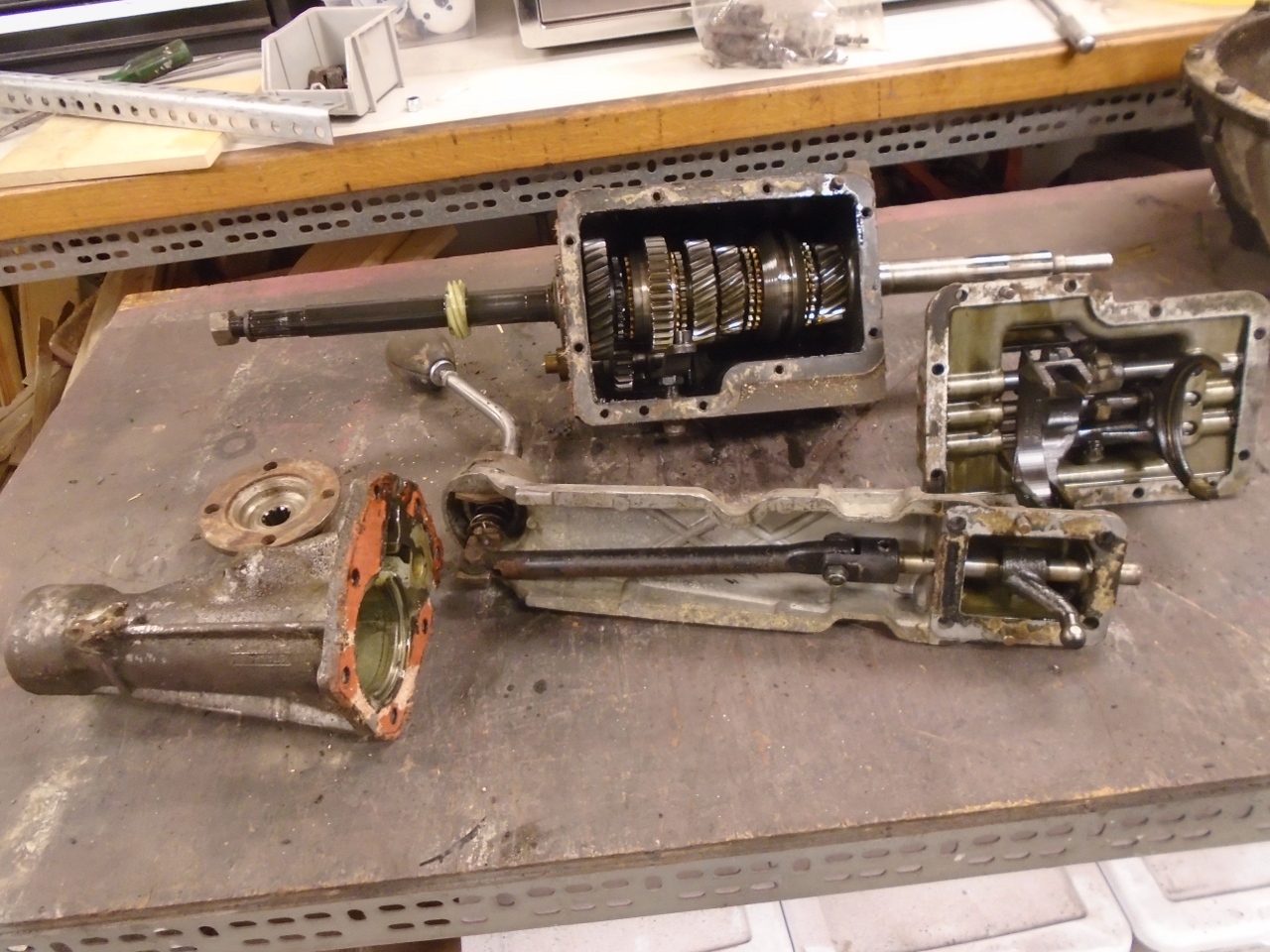
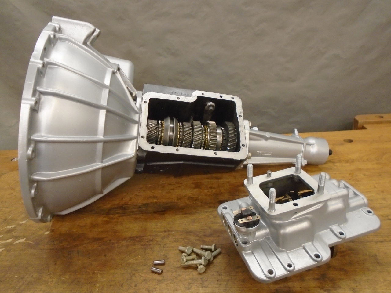
The GT6 gearbox assembly is made up of five subassemblies:
the gearbox itself, where all the gears are,
the bell housing, which encloses the clutch and flywheel,
the tail extension, which supports the rear of the output shaft and includes the speedometer drive,
the gear selector, which coordinates gear selection and prevents more than one gear at a time being engaged, and
the remote control, which puts the shift lever within easy reach of the driver.
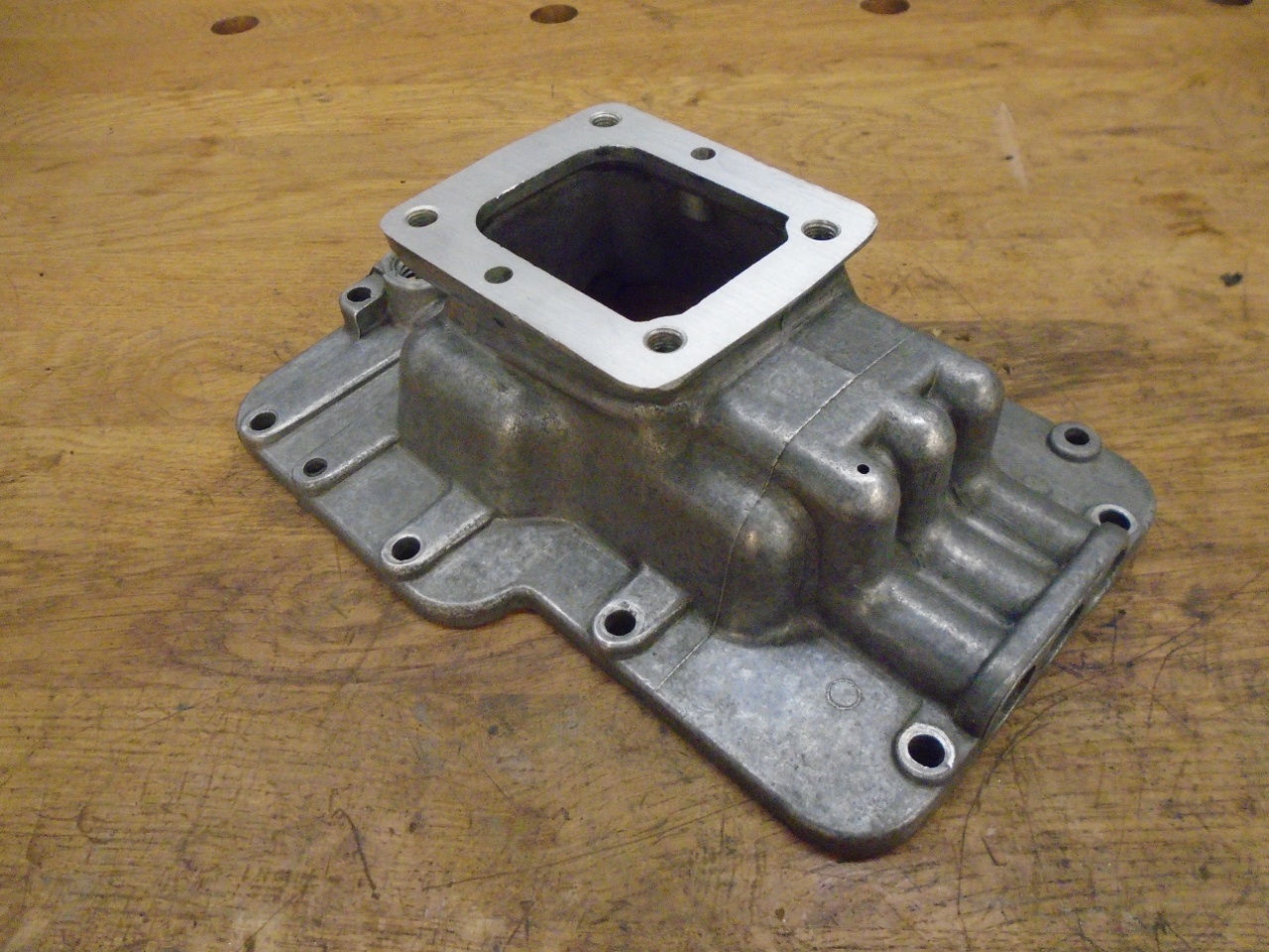
I started at the top, with the remote control assembly. To jump directly to the gearbox itself, click here.
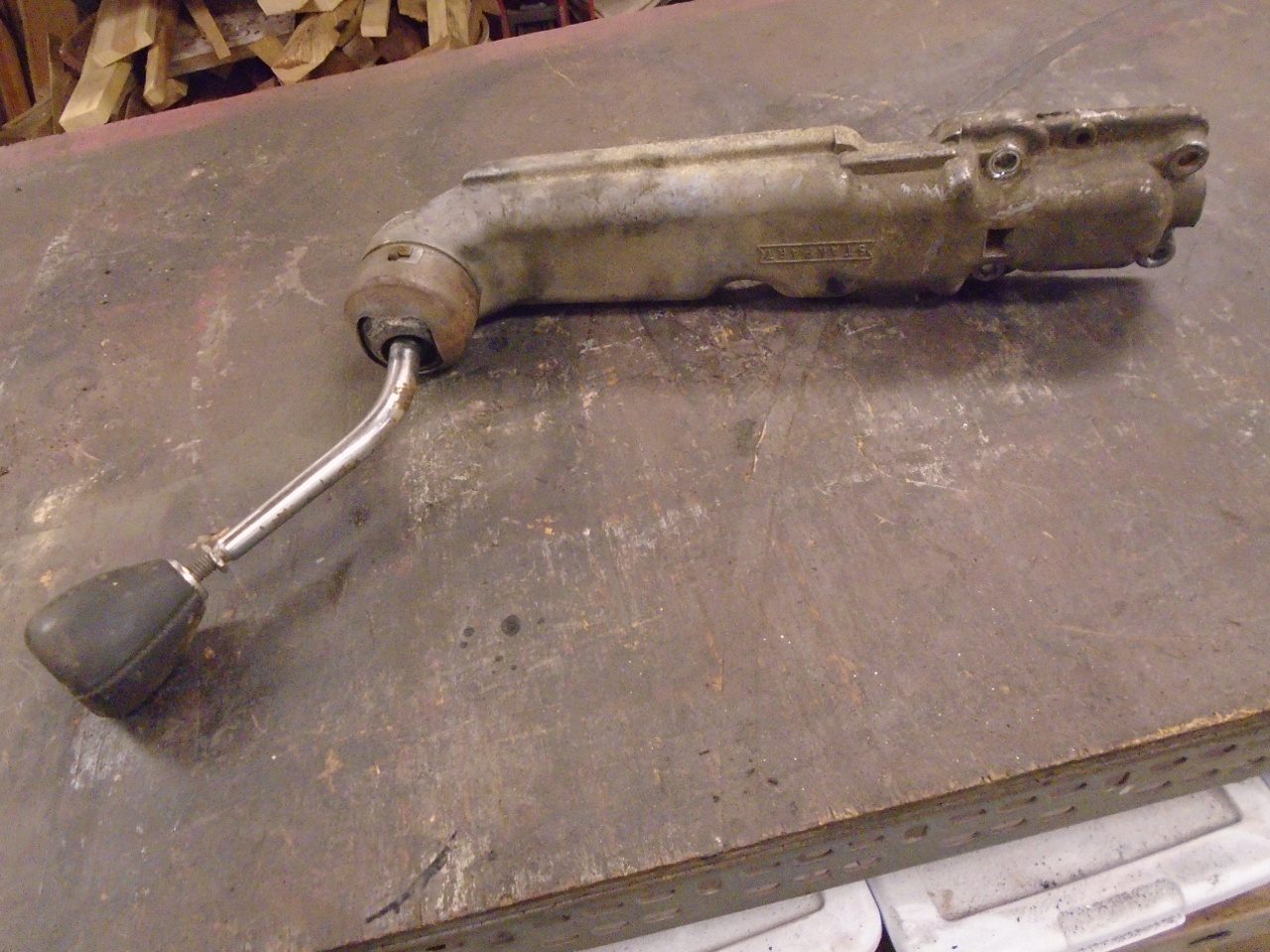
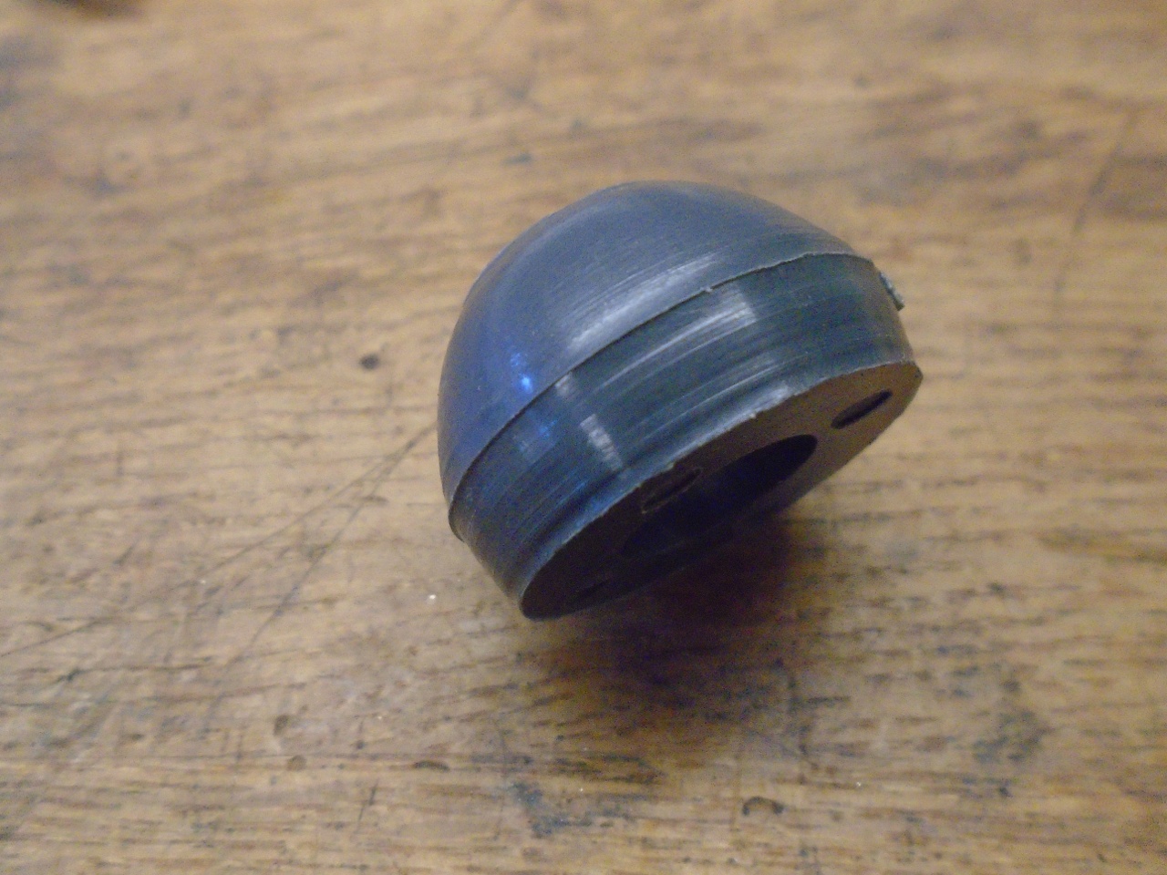
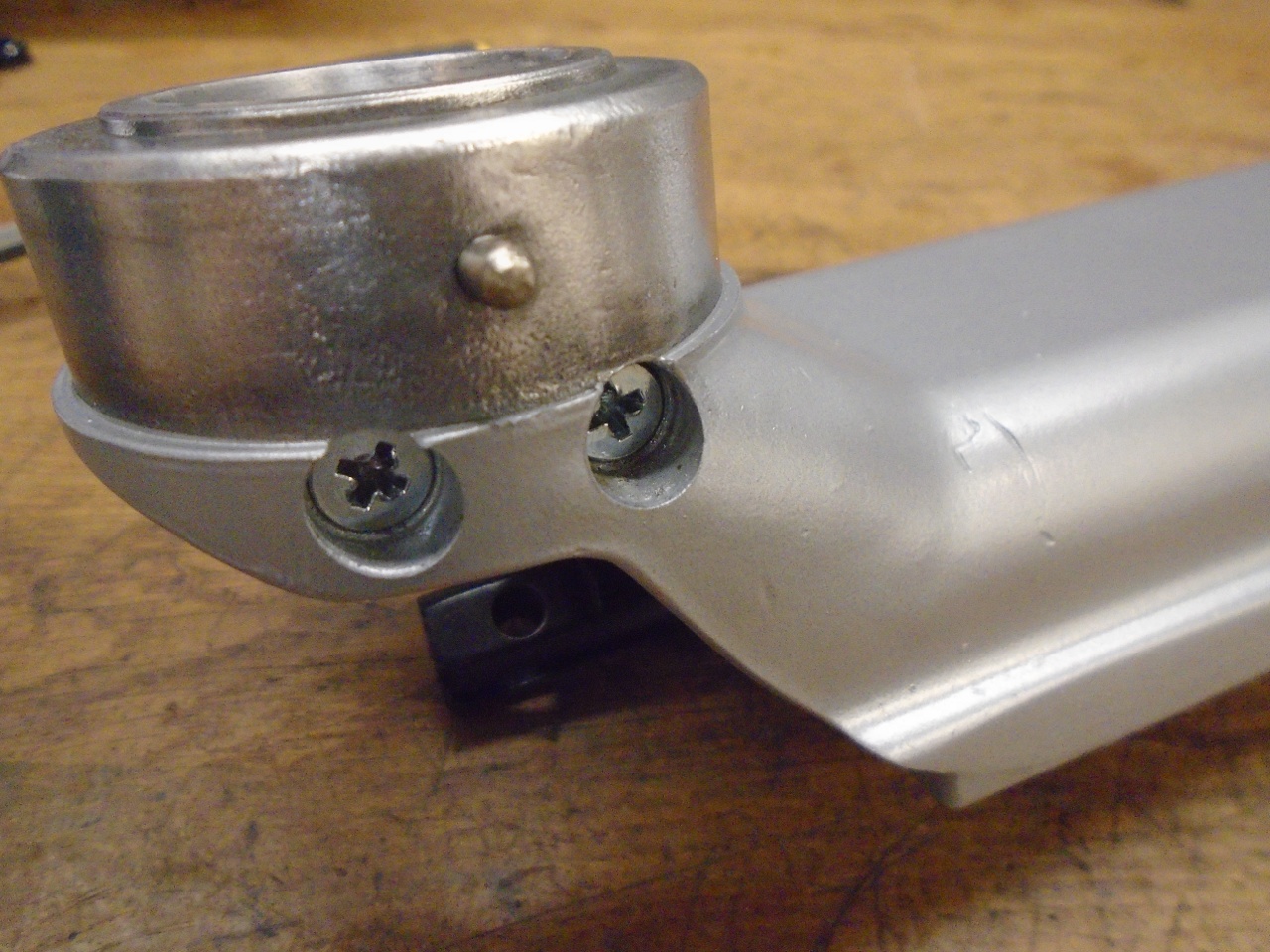
The
first thing I norticed about the remote control was that the selector
lever was very loose and sloppy. Taking it apart, there appeared
to be at least one part missing.
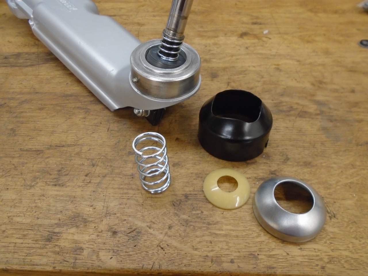
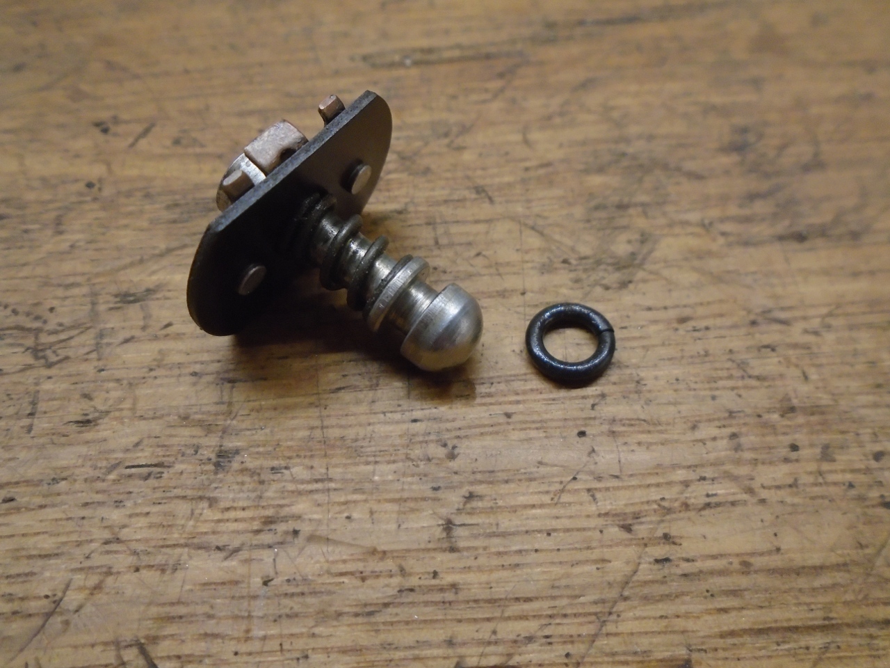
There
is a kit of parts available to tighten up the lever, so I ordered one.
The missing part was the nylon half-ball that fits at the base of
the lever, and rides in a spherical socket in the housing. The
ball in the kit was pretty rough, with pretty pronounced casting flash.
It didn't ride very smoothly in the socket. It took a
little work to clean it up, and it then worked fine.

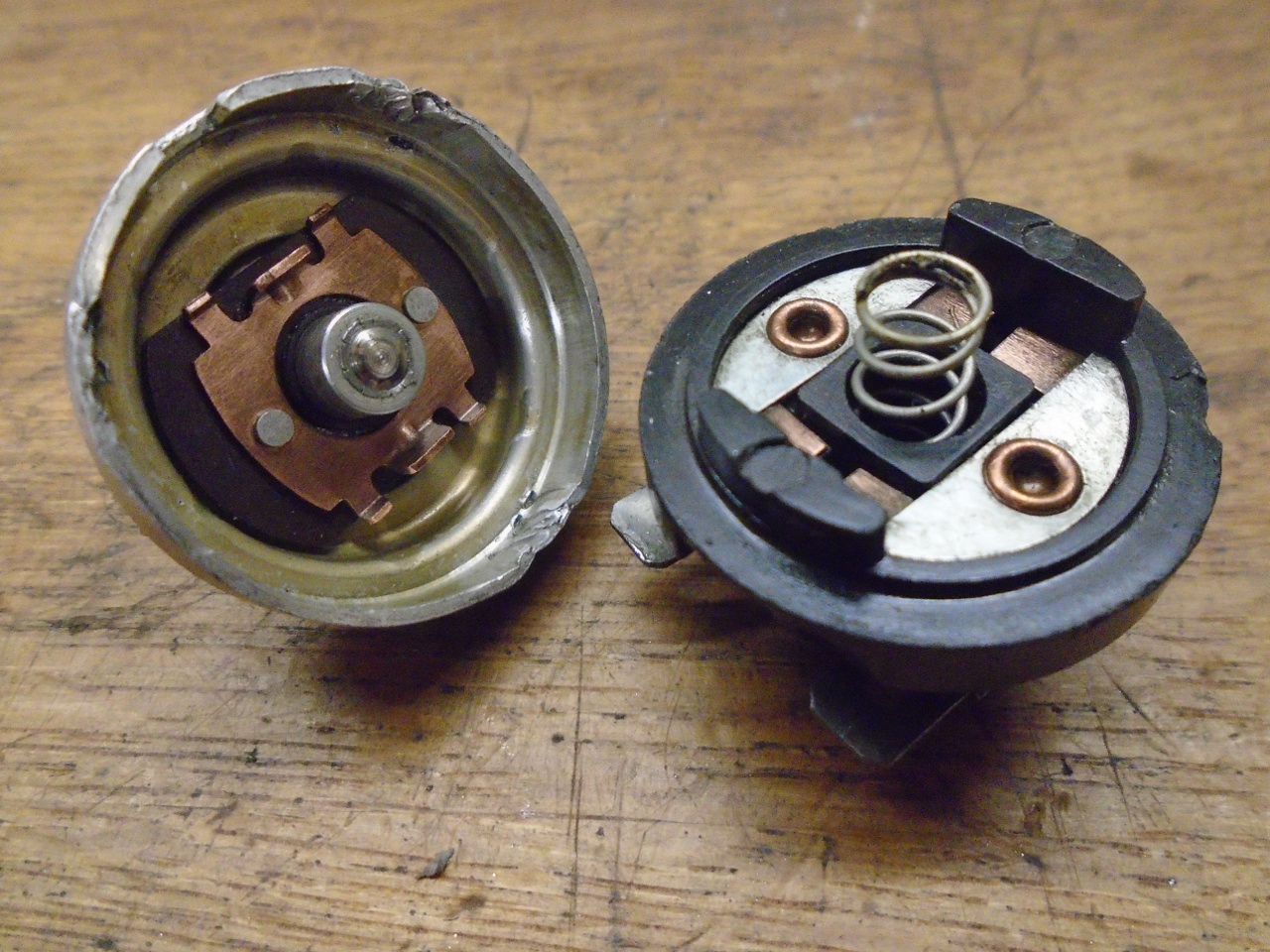
A
few of the other parts in the kit were sort of disappointing. I
ended up replating and re-using this original retainer rather than the
new one (new one on the left).

For
the rest of the parts, I used a mix of the old and new, whichever
worked better. I powder coated most of the exposed parts,
including the aluminum housing.
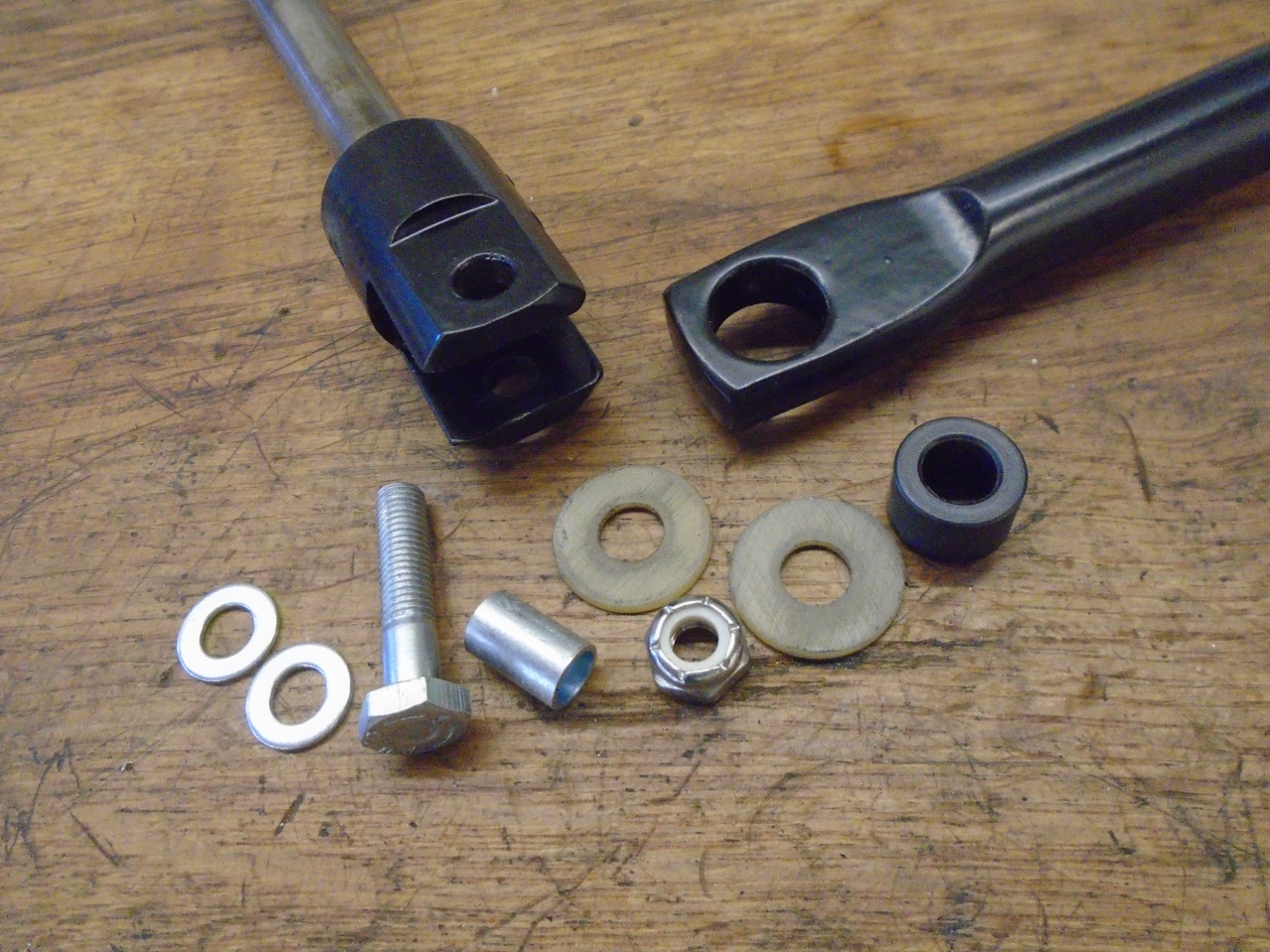

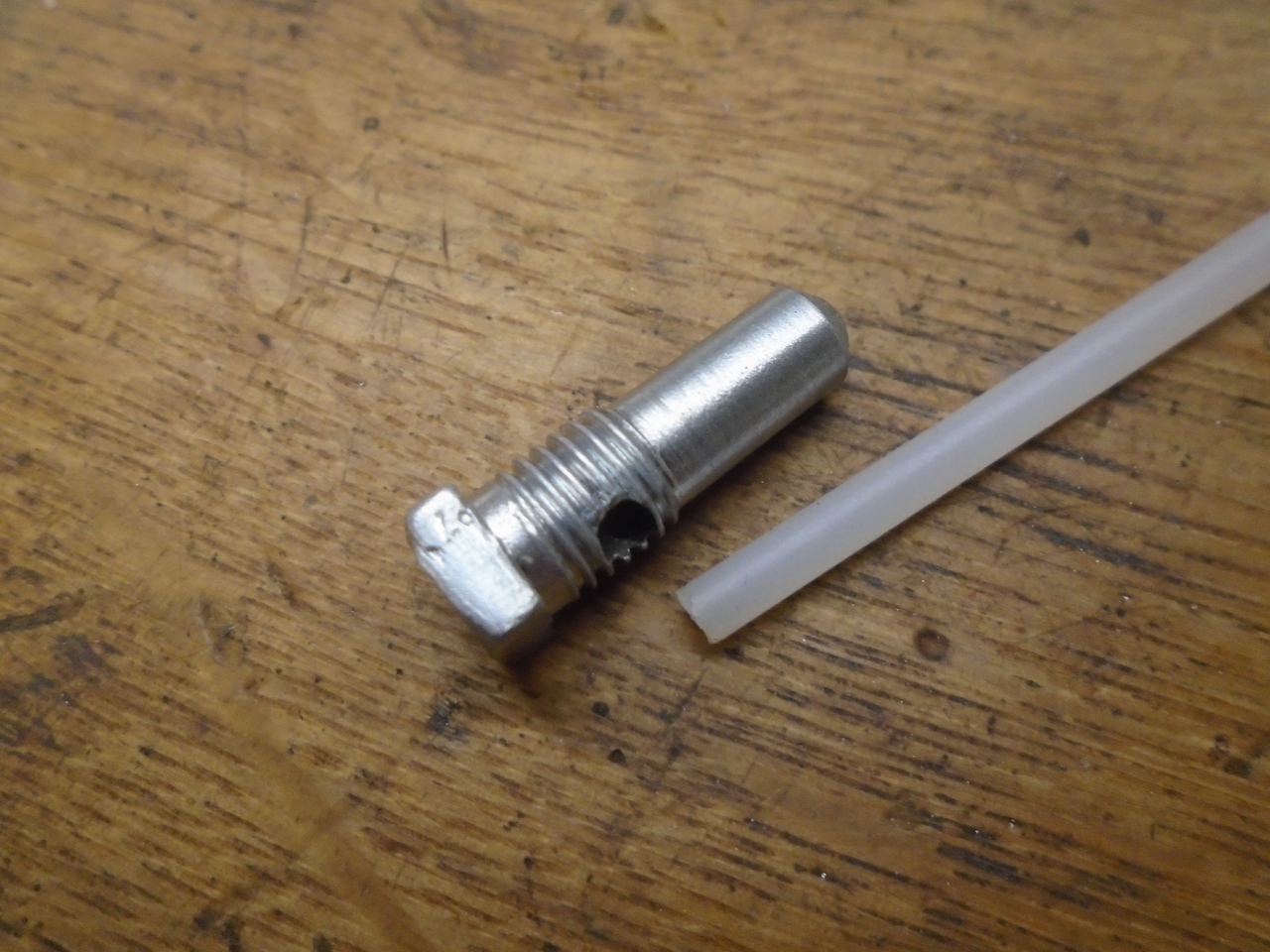
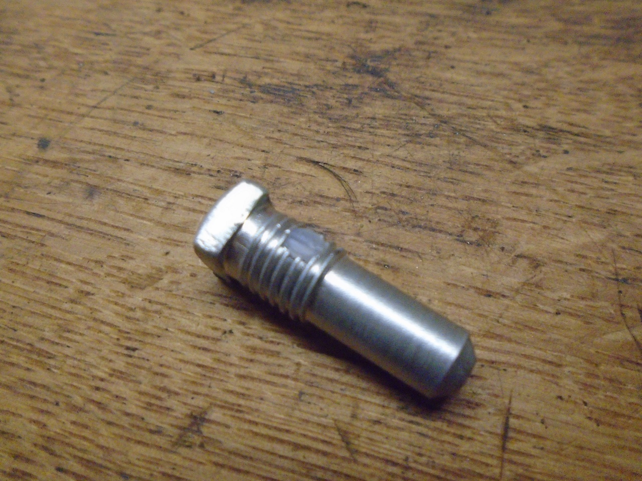
The
square-head bolt that retains the selector finger was actually a lock
bolt, with a little nylon pellet inserted in the threaded portion.
Like "Nylok" nuts, these really shouldn't be re-used. I
didn't really want to wait (or pay) for a new bolt, so I found
some 1/8" nylon rod and just made a new insert.
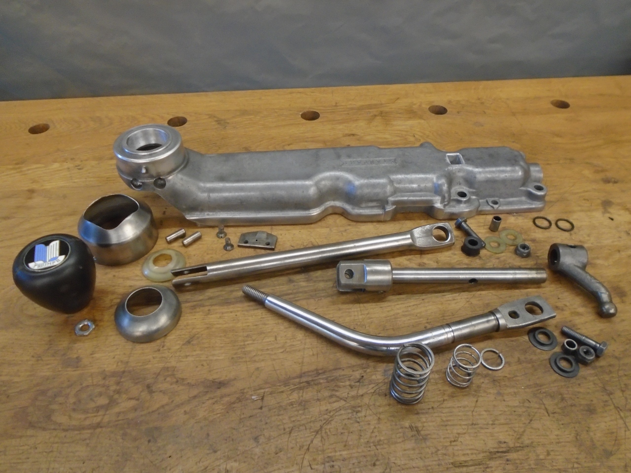
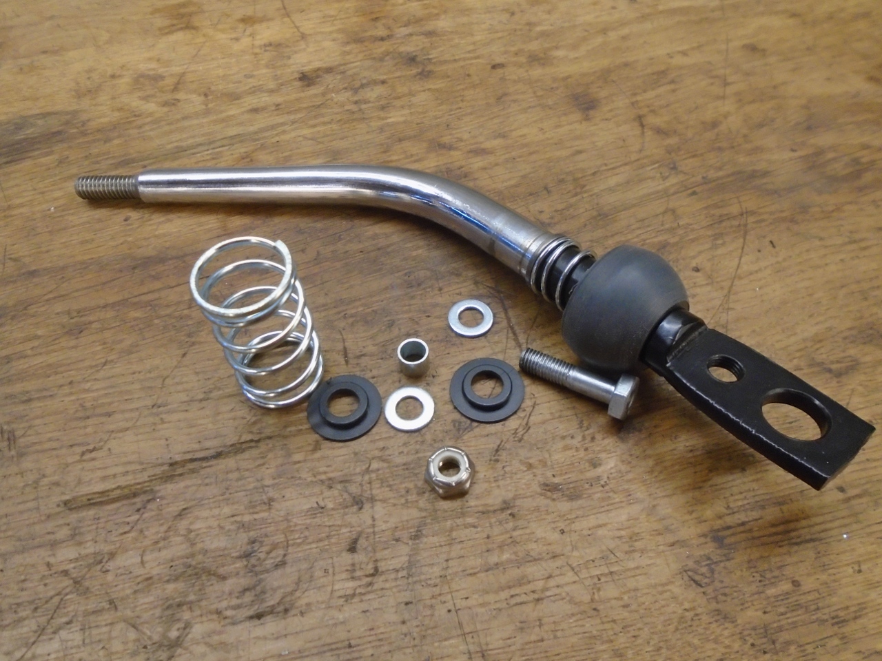
This is all the moving parts assembled except fot the shift lever.
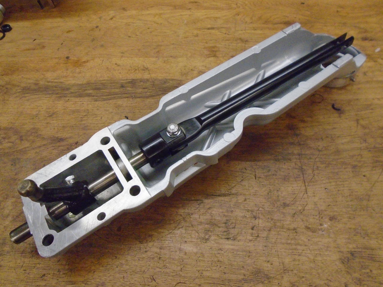
This is the reverse lockout tab, which makes it harder to accidentally shift into reverse.
Then the shift lever was installed. It now works firmly but smoothly.
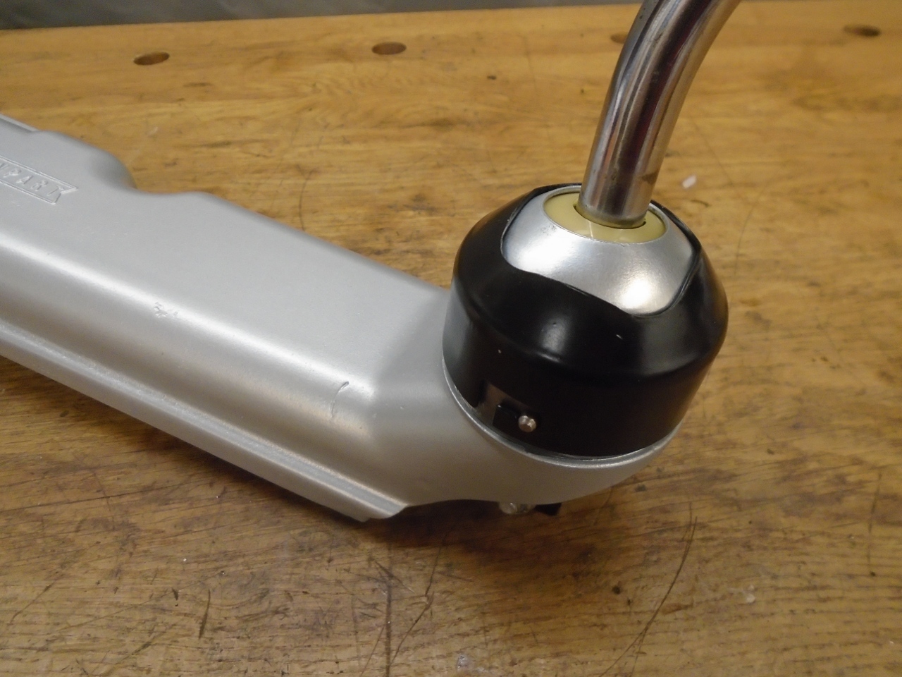
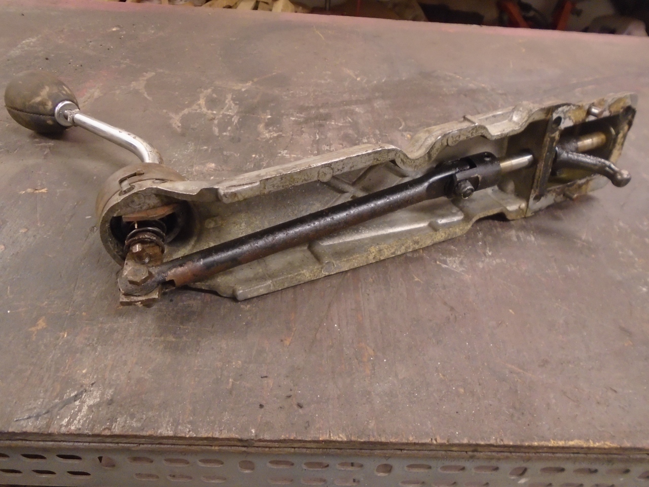
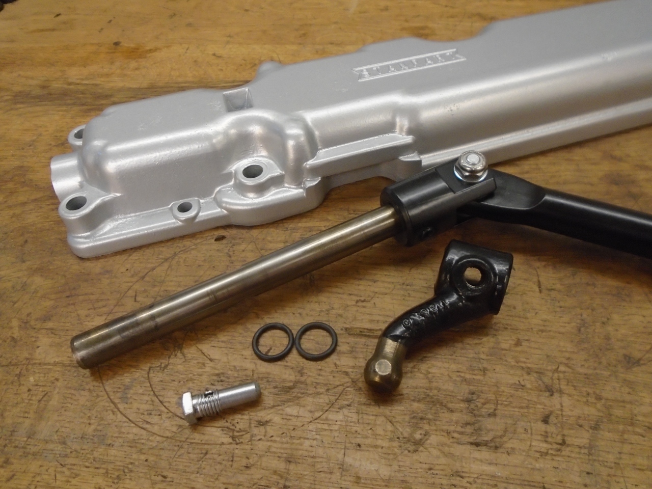
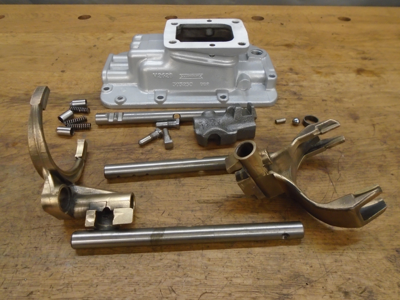
The
shift lever on the remote control manipulates internals of the gear
selector assembly, which in turn moves parts inside the gearbox.
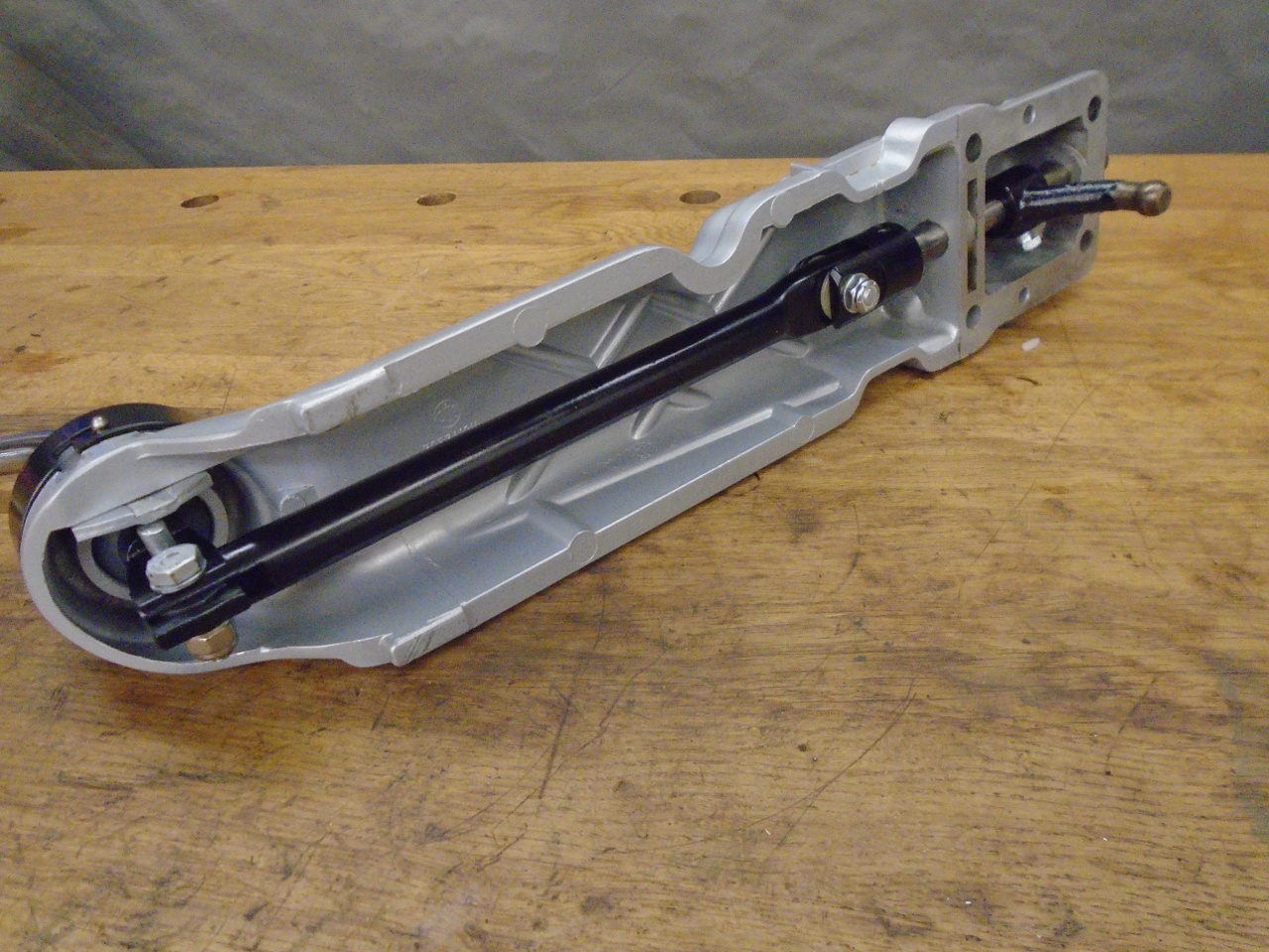
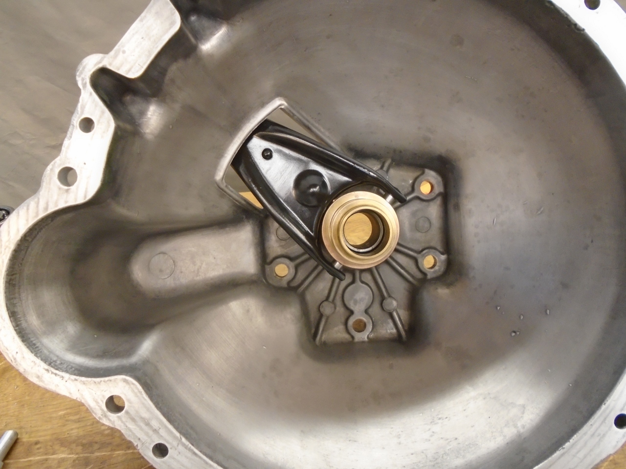
It moves those parts by way of bronze selector forks.
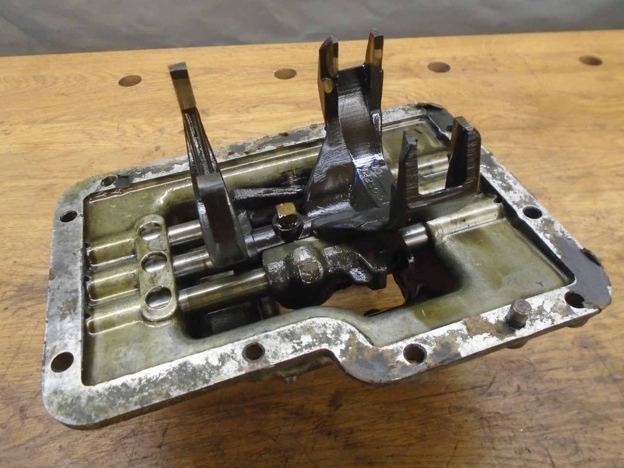
The
forks are attached to three rods that can move fore and aft, controlled
by motion from the shift lever. One rod controls first and second
gears, another controls third and fourth, and the third rod controls
reverse.
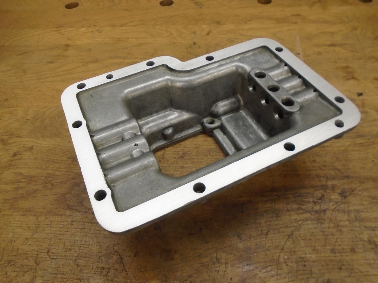
I like to linish mating machined surfaces on a plate to make sure they are flat.
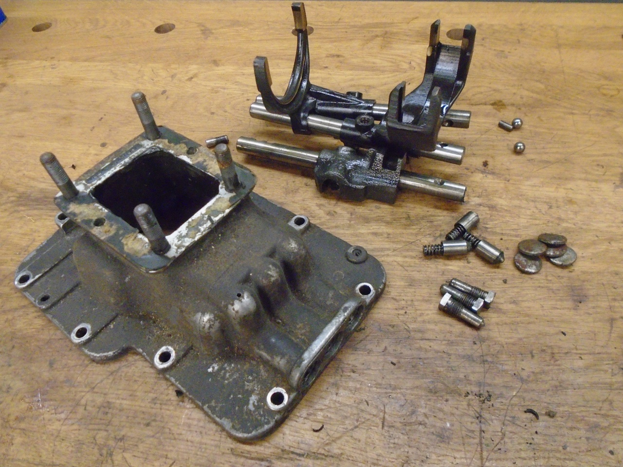
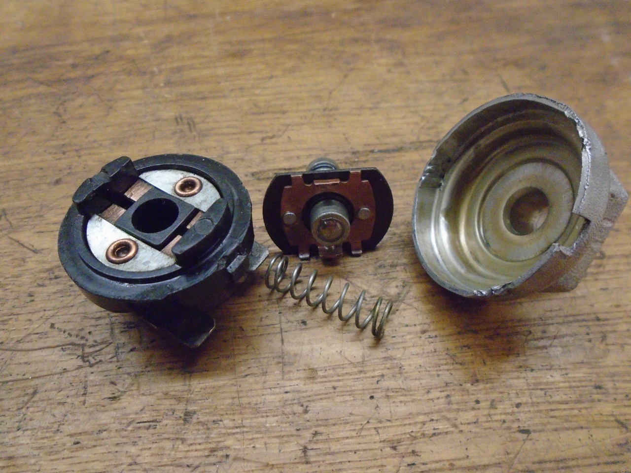
Here
are all of the parts cleaned and inspected, and the housing powder
coated. The selector assembly includes an interlock mechanism to
prevent more than one rod and selector fork from moving at the same
time. This would cause more than one gear to be engaged, which
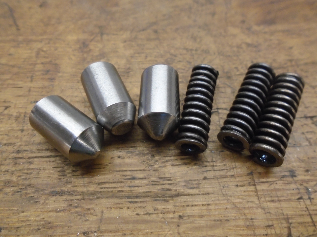
would be confusing for the gearbox. The little pin and ball on
the right side of the picture are part of the interlock. All of
the parts listings I saw only called for one ball, but two are
actually required for full interlock.
The
selector assembly also provides fairly strong spring loaded detents for
each rod, which provide a good positive feel for shifting, and also
ensure that the gearbox won't pop out of gear. The more blunt
detent is for the reverse rod.
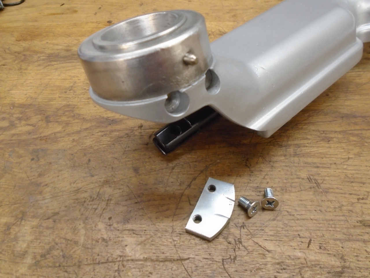
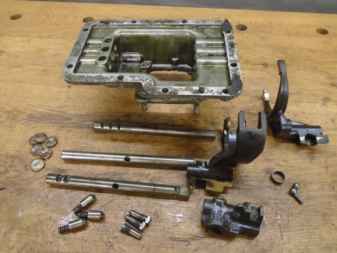
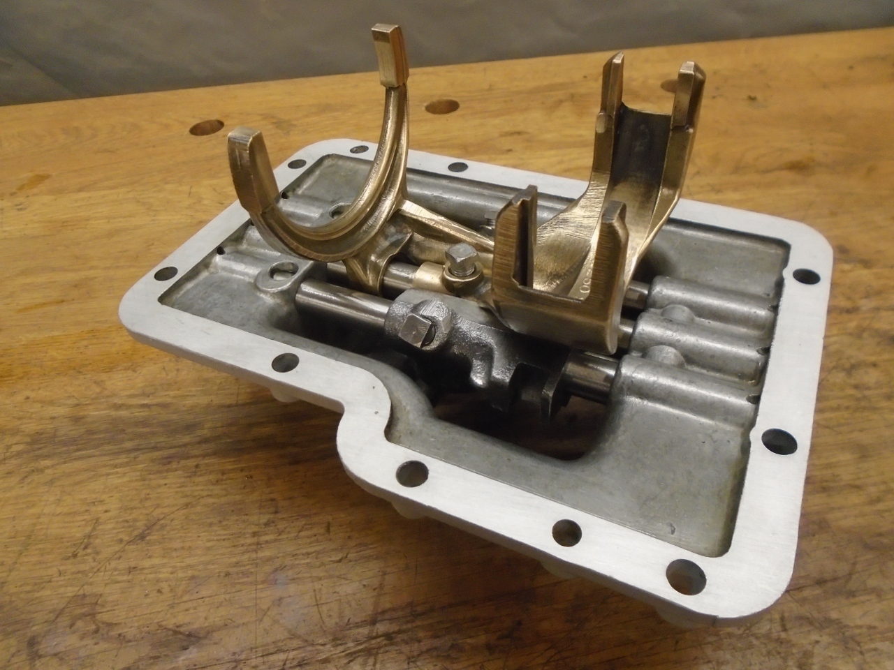
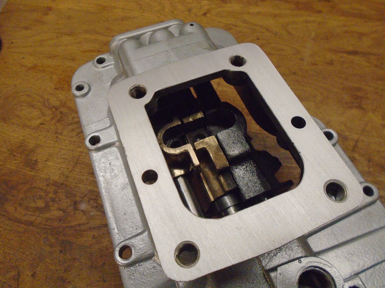
Here
is everything put back in the housing. The forks are attached by
three more of those square head lock bolts that got new nylon buttons.
The third picture shows the slot that the finger from the remote
control fits into..

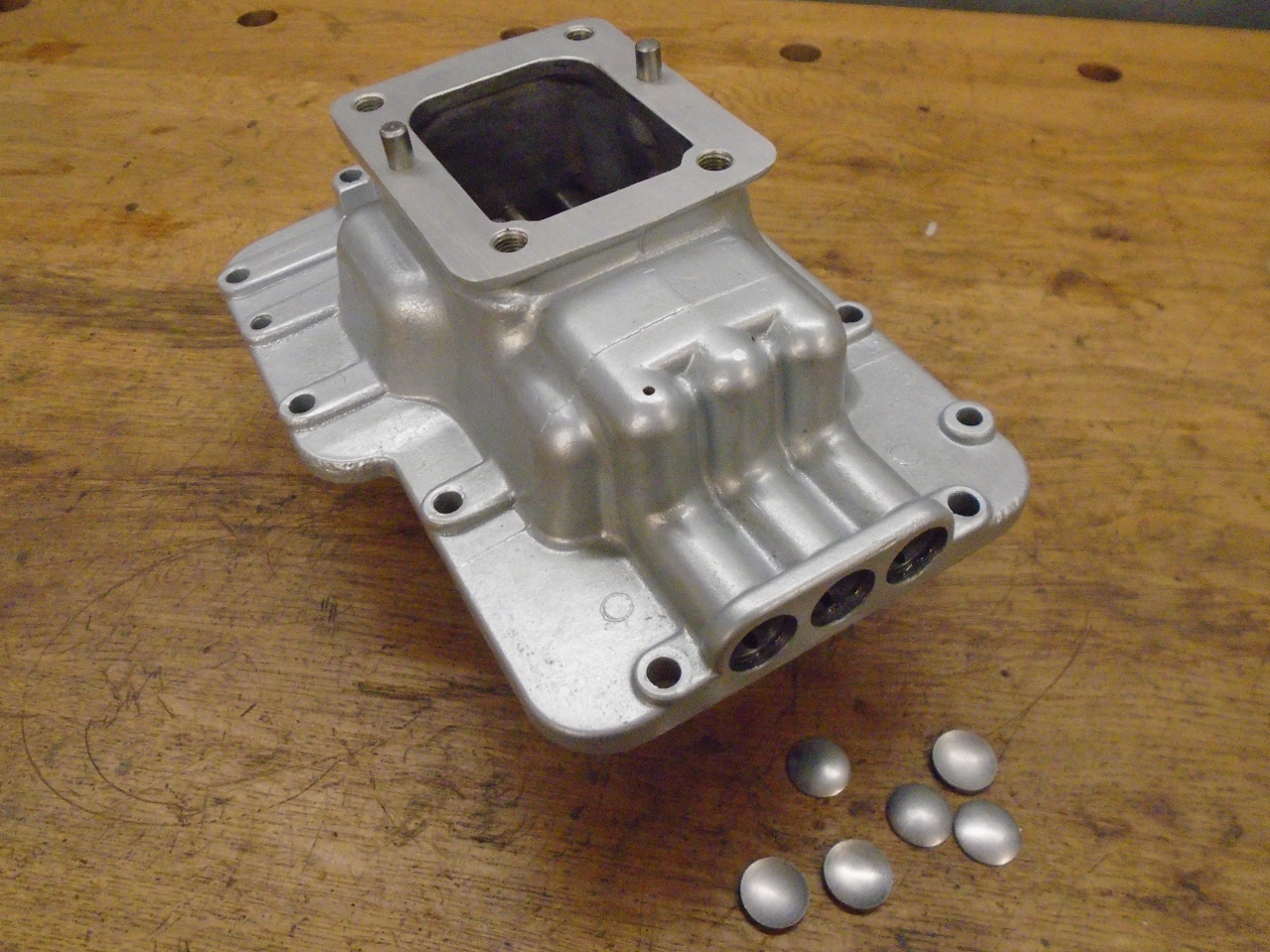
The
bores that the three control rods slide in are open at both ends of the
housing. They have to be closed off with small core plugs.
I'm not sure what the LBC suppliers have, but these came from an
industrial supplier, and were not plated. A quick zinc plate
fixed that right up.

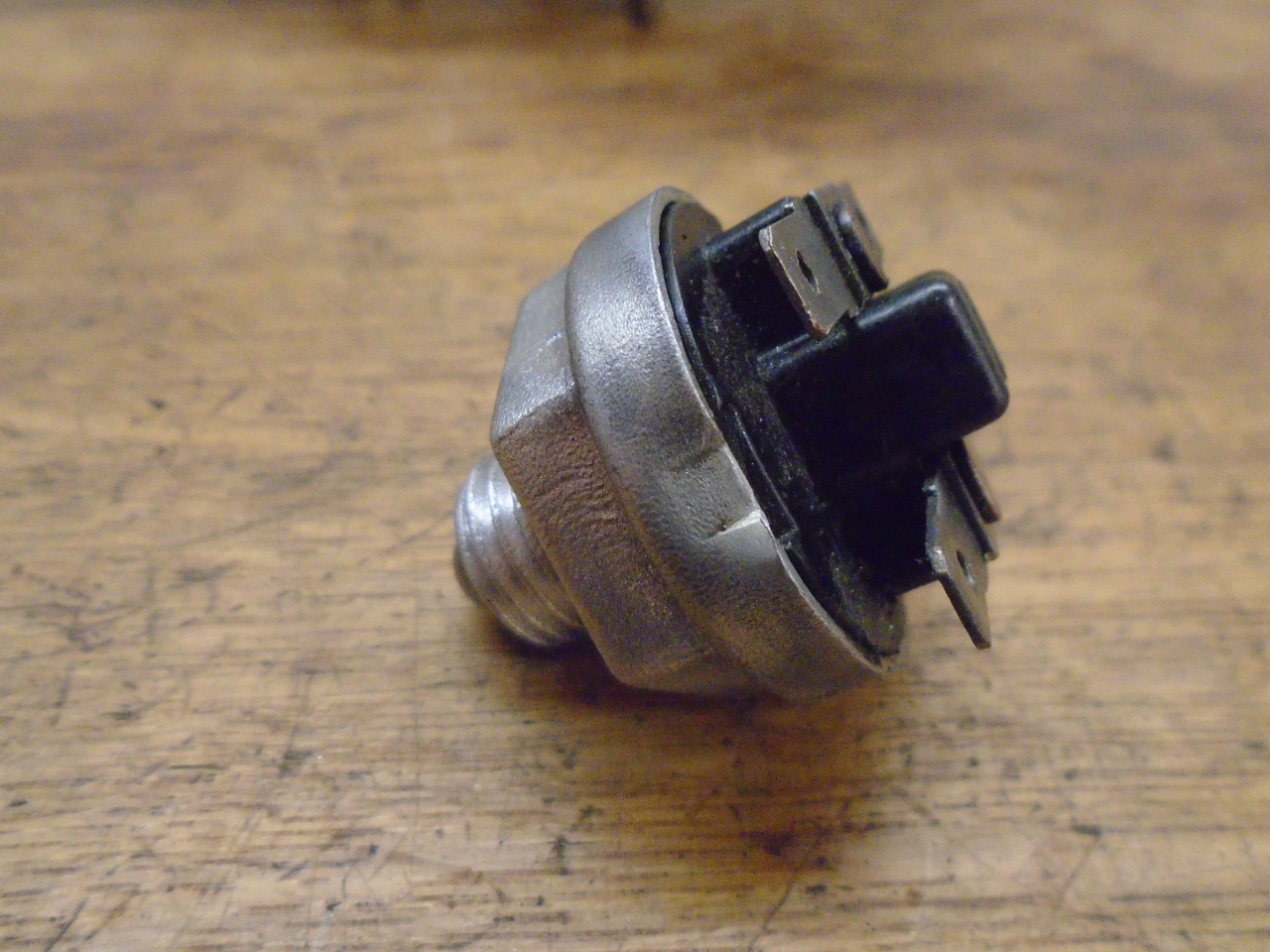
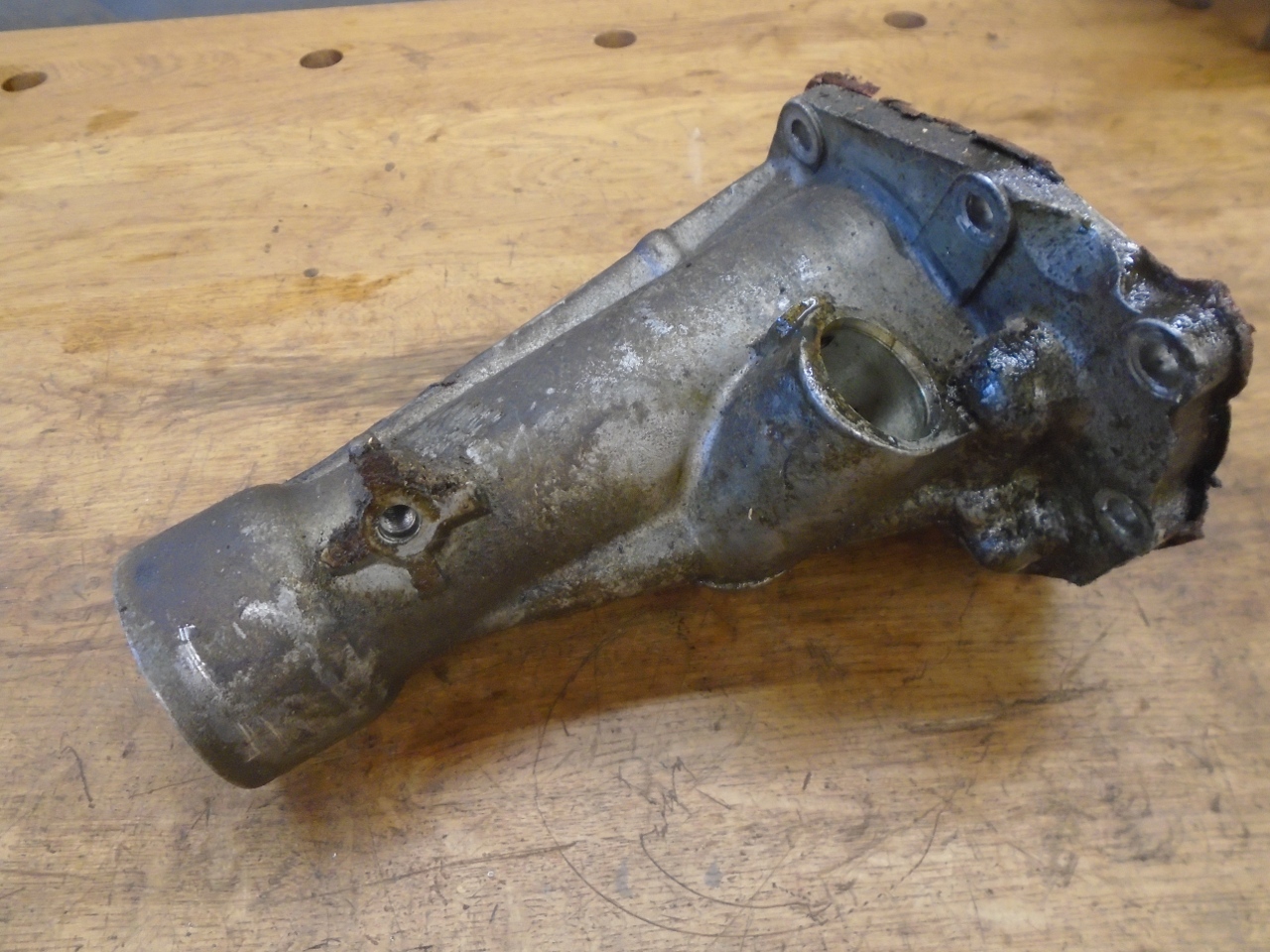
This
is the reverse switch which controls the backup lights. A test
with an ohmmeter showed that it was not working. I didn't thiink
I had a lot to lose by trying to fix it.
It was pretty grody inside, apparently from leaked oil., but the parts cleaned up well.
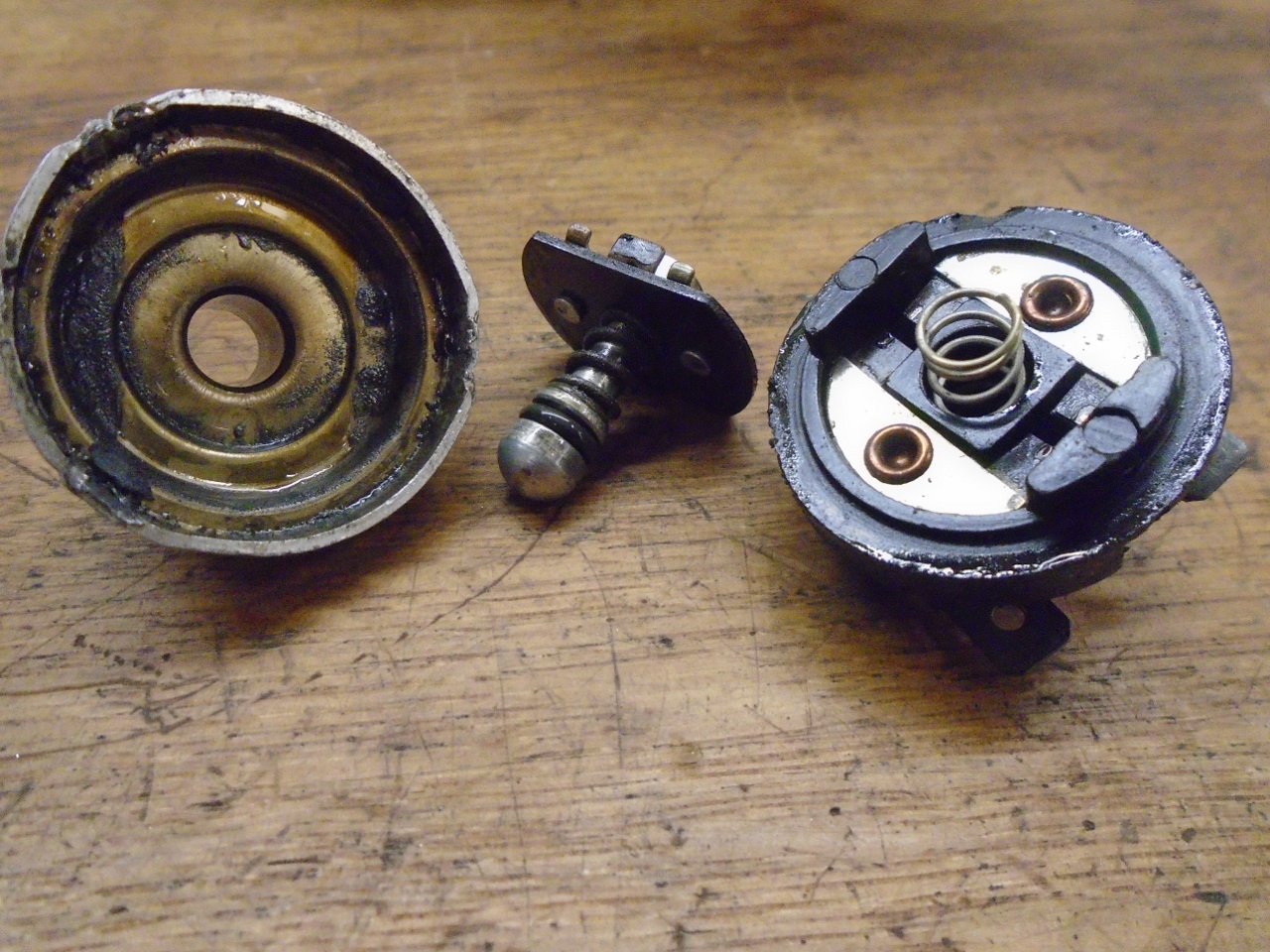
This
O ring on the actuator button was hard and cracked, and surely the
source of the leaked oil. It's a standard size O ring.
All renewed and reassembled, and it worked!
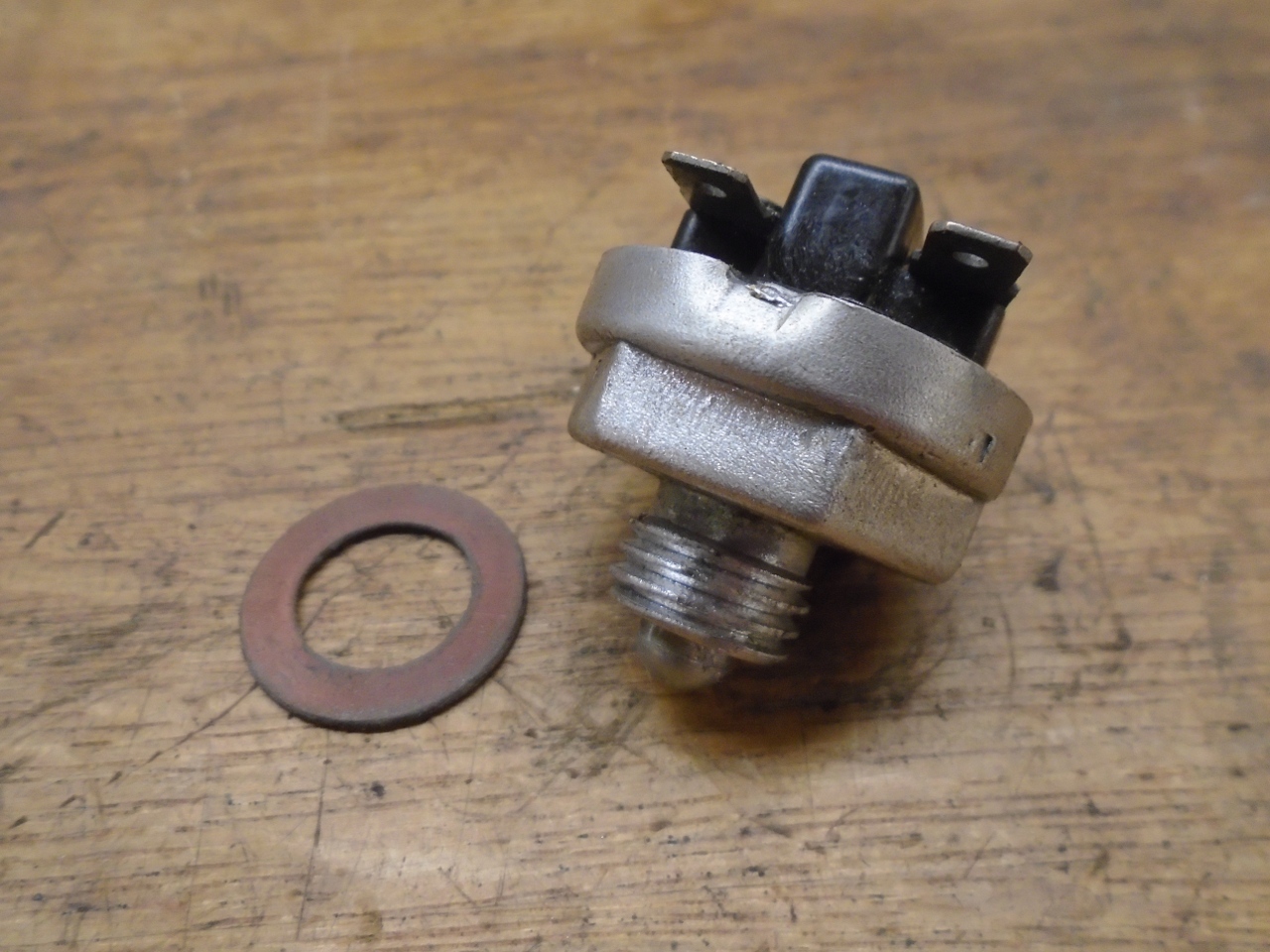
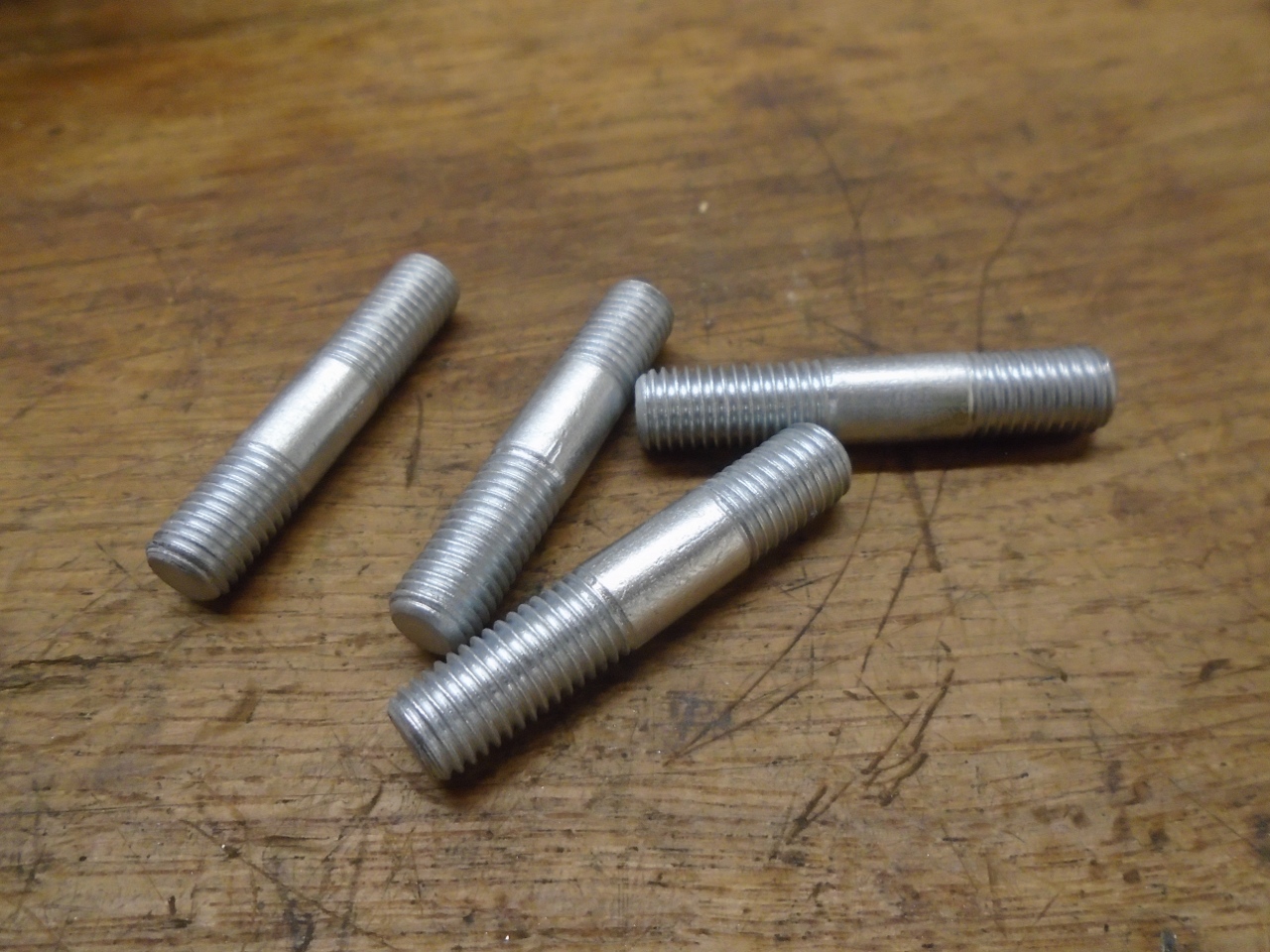
Cleaned and replated the original studs, and this piece is ready.
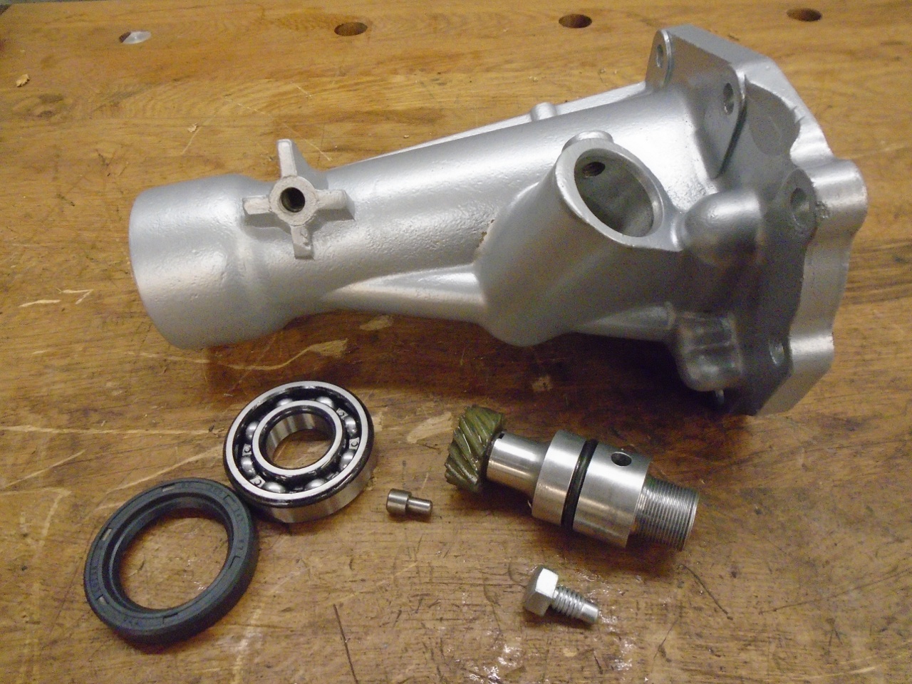
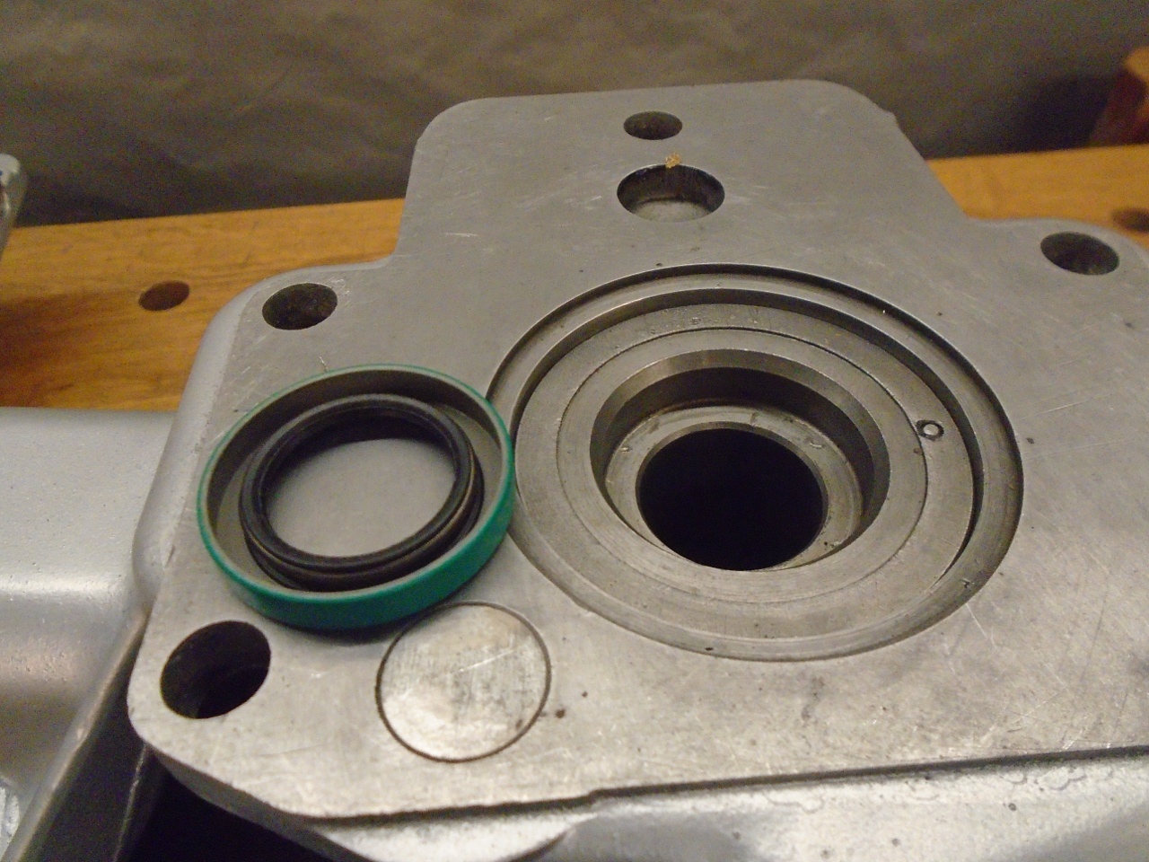
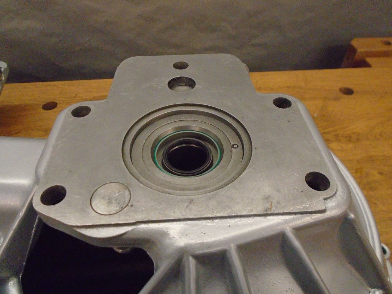
The
tailpiece is simpler than the shifter subassemblies. After
pulling everything out of it, the casting was cleaned up,
linished, and powder coated.


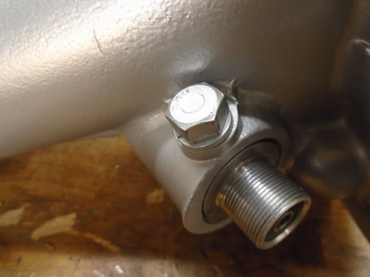
The
speedometer drive assembly got a new seal and O ring. That little
stepped rod is a thrust seat that goes in the housing to limit play of
the gear.
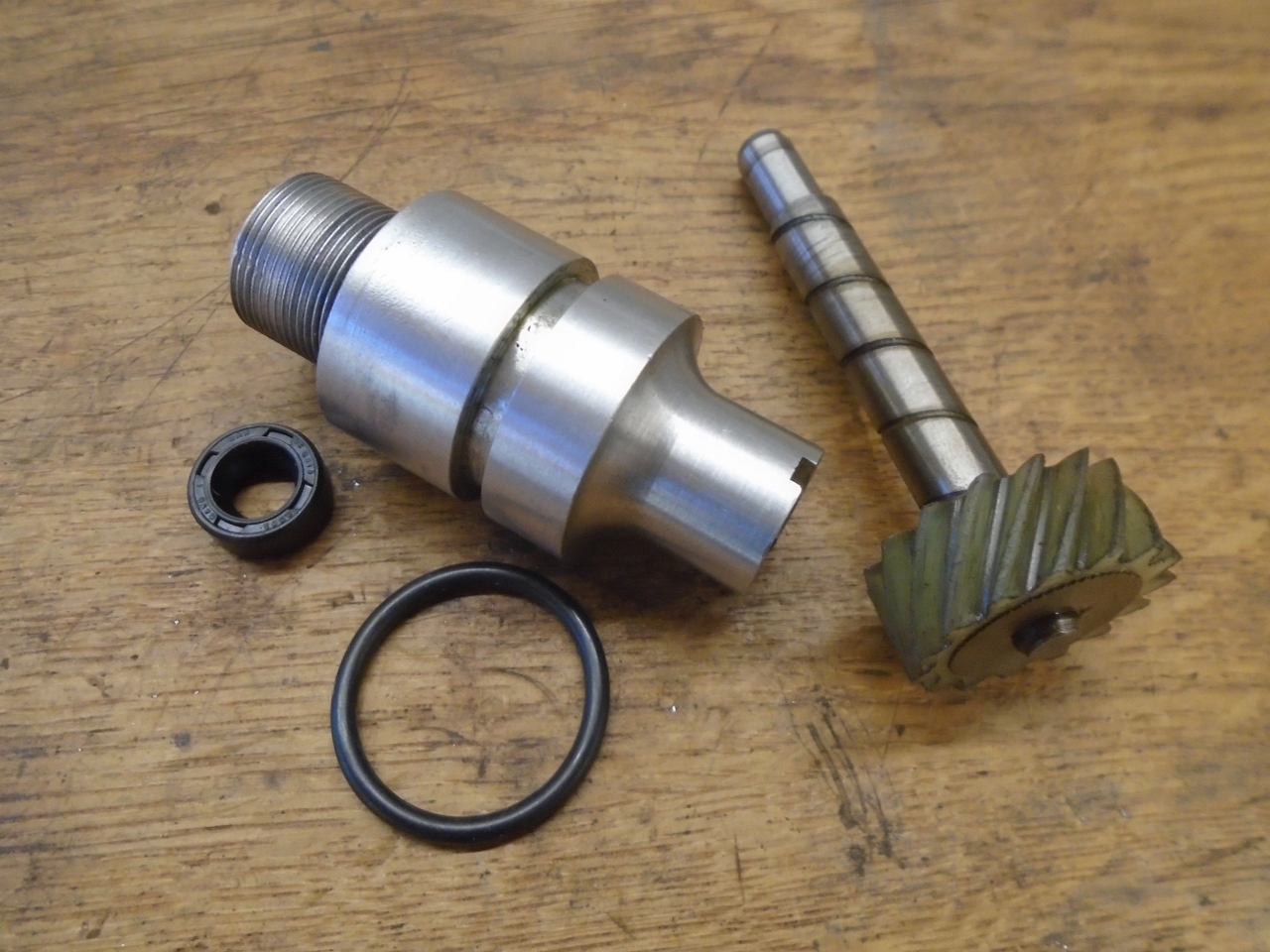
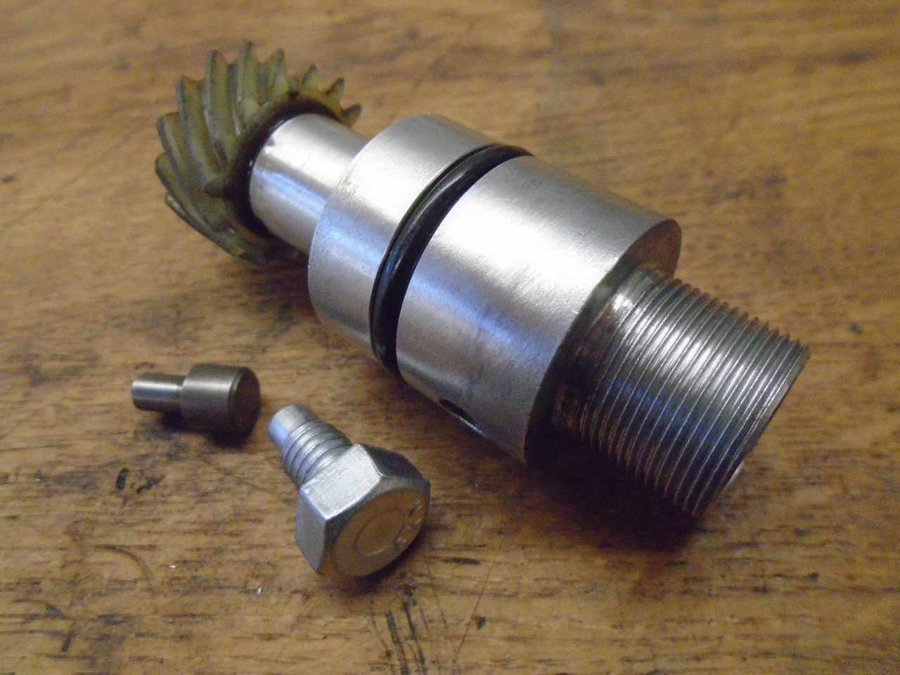
The only other parts are the bearing and oil seal for the rear end.
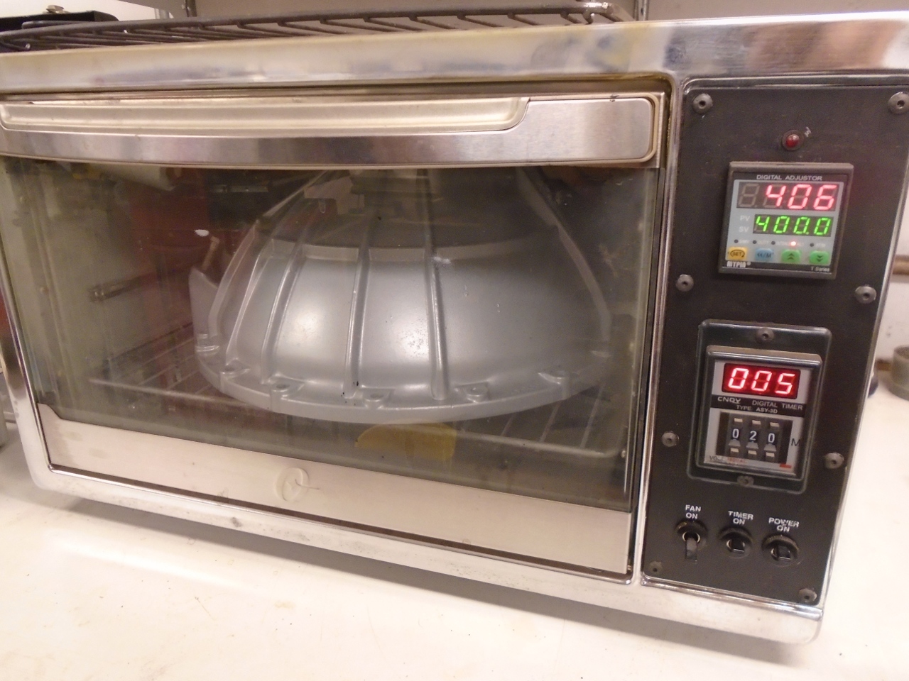
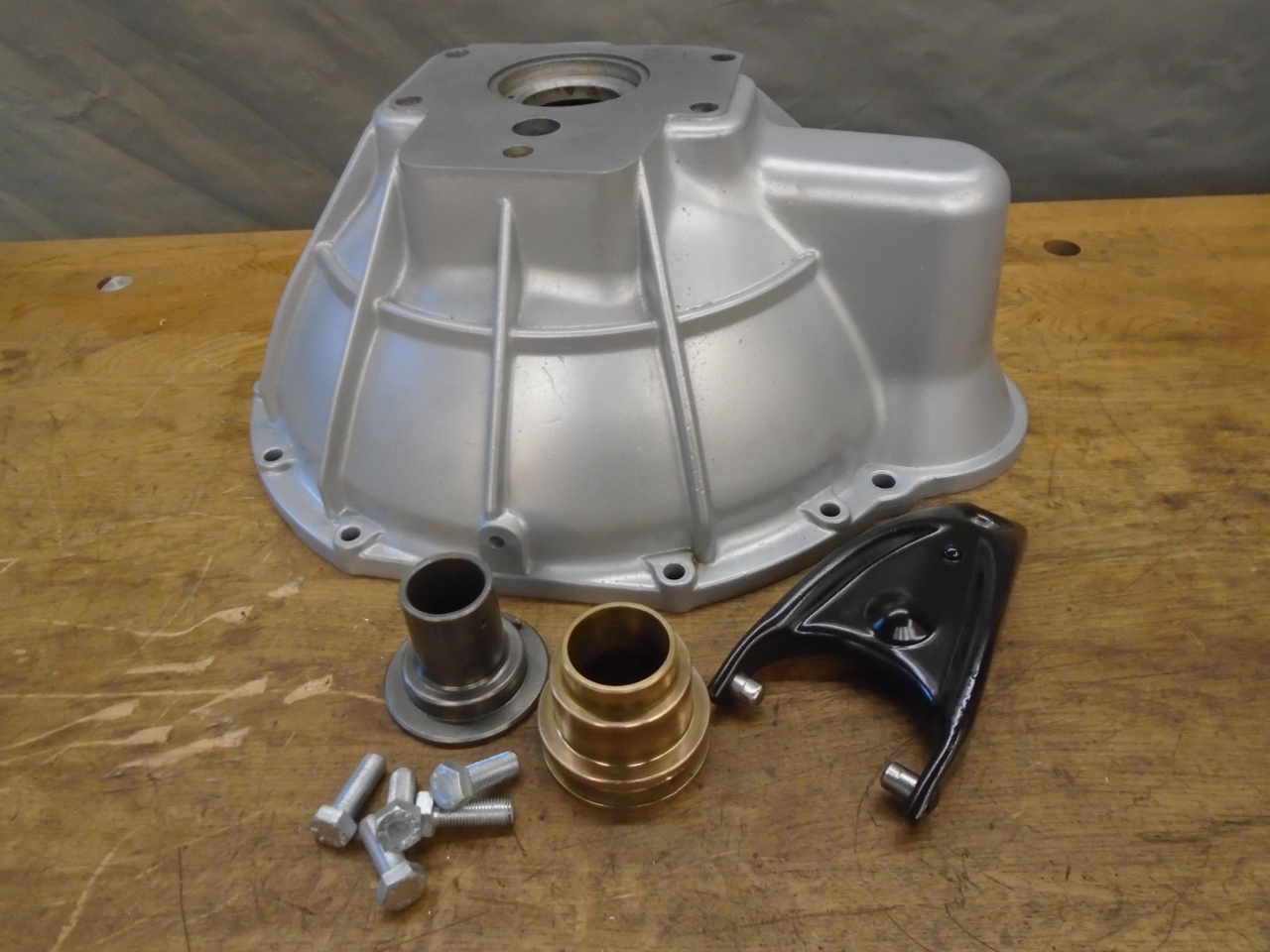
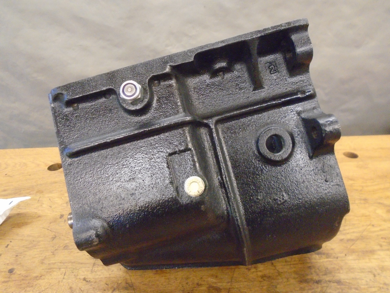
The
bell housing is the simplest assembly. It was stripped, cleaned,
and powder coated. I had my doubts, but it did fit in my smallish
oven, with probably a half an inch all around.

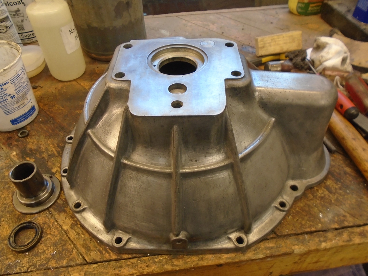

Then
the nose piece was pressed in, then the oil seal. The throwout
bearing carrier will have to come out again to install the bearing.
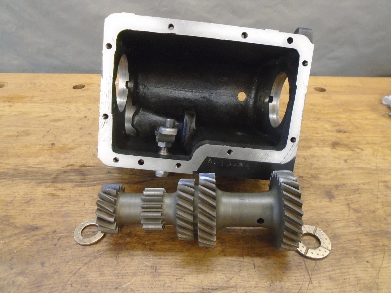
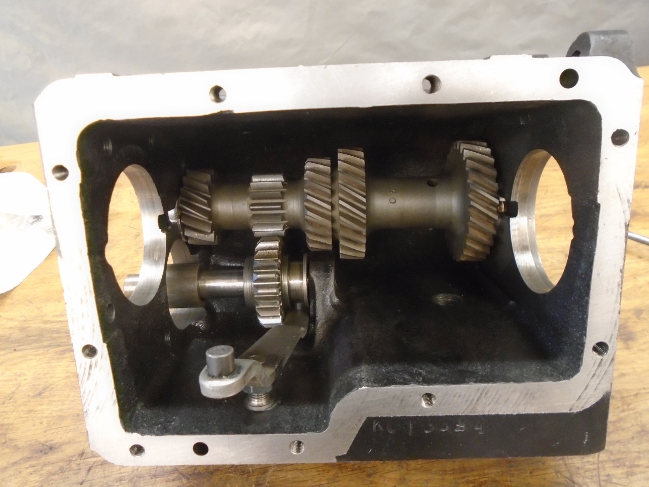
And
now to the main event. Peering into a gearbox can be a little
intimidating. There are a lot of parts crammed in there, and the
way they have to fit together is very often not intuitive. I
don't recommend anyone try this without at least two good manuals.
The factory manual is very good, but it mentions quite a few
special factory tools which are difficult or impossible to find.
Non-factory manuals will often recommend techniques that don't
require the factory tools.
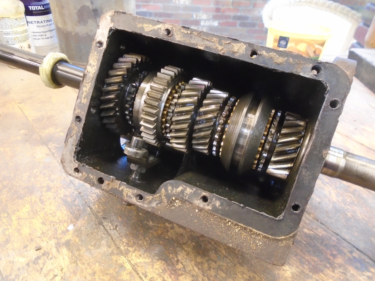
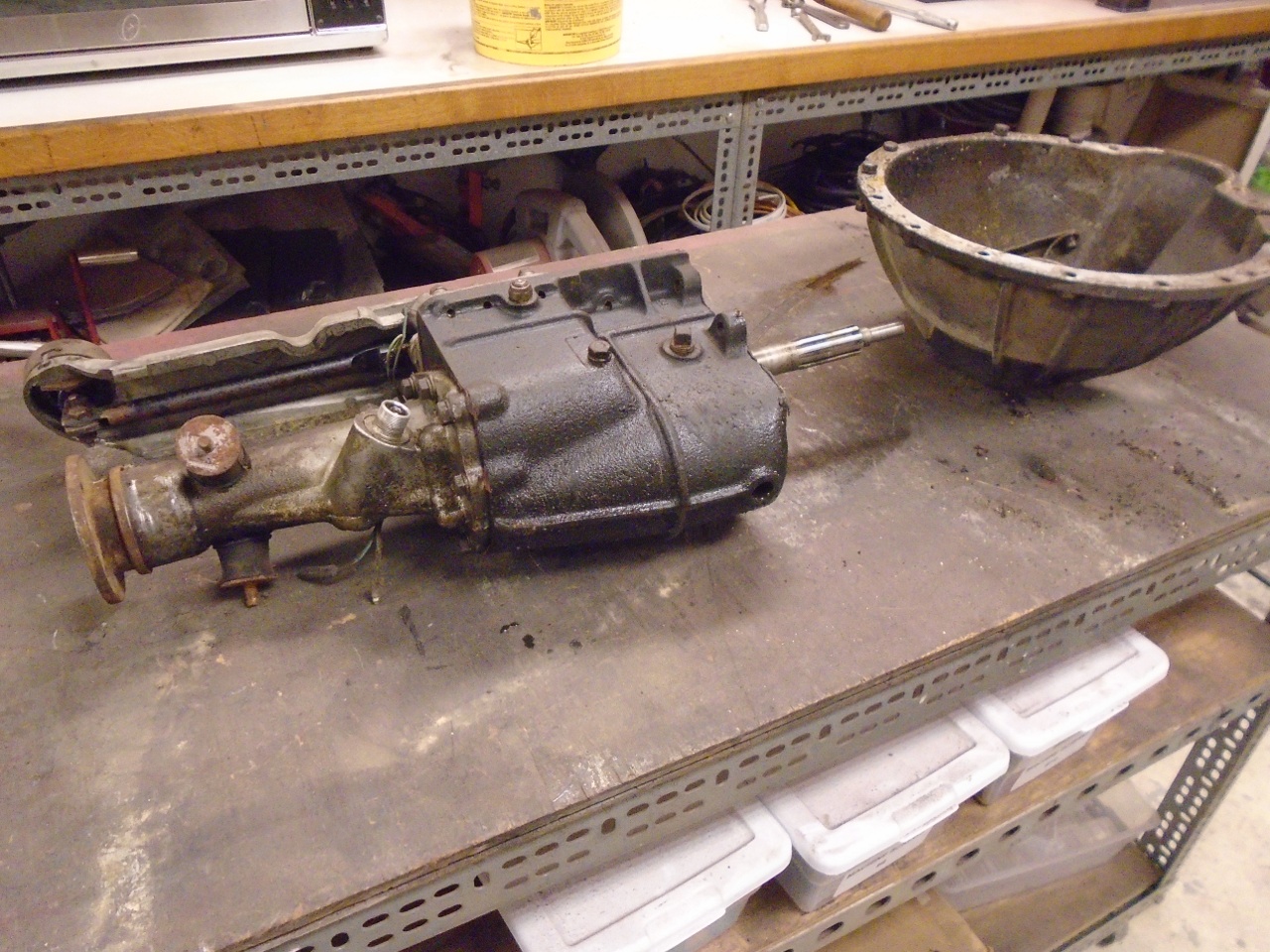
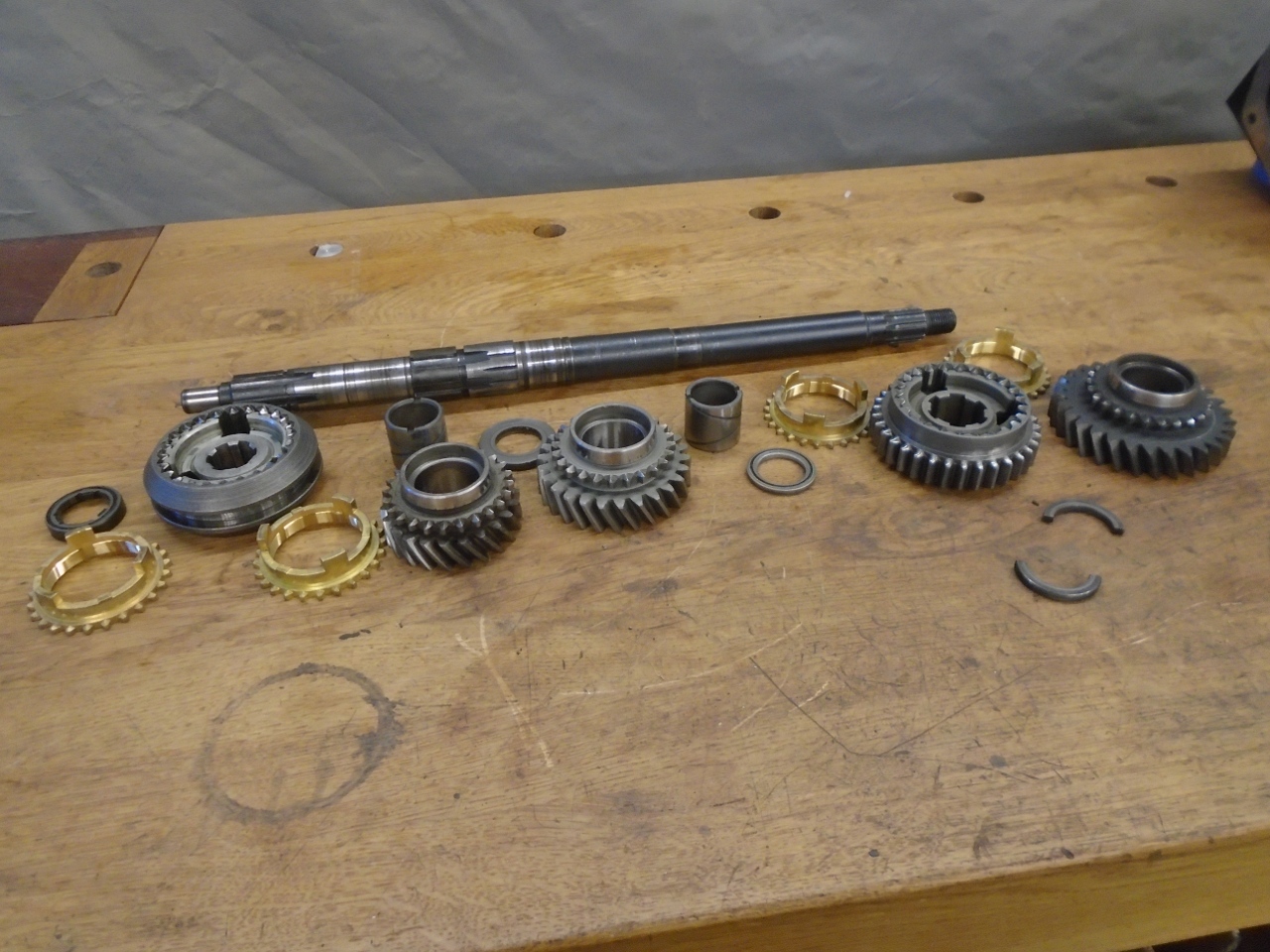
So I gutted the gearbox, trying to keep things in order and in the correct orientation.

I
cleaned and visually inspected each part, looking for damage or
excessive wear. I didn't really find anything worrisome, so I
moved on.
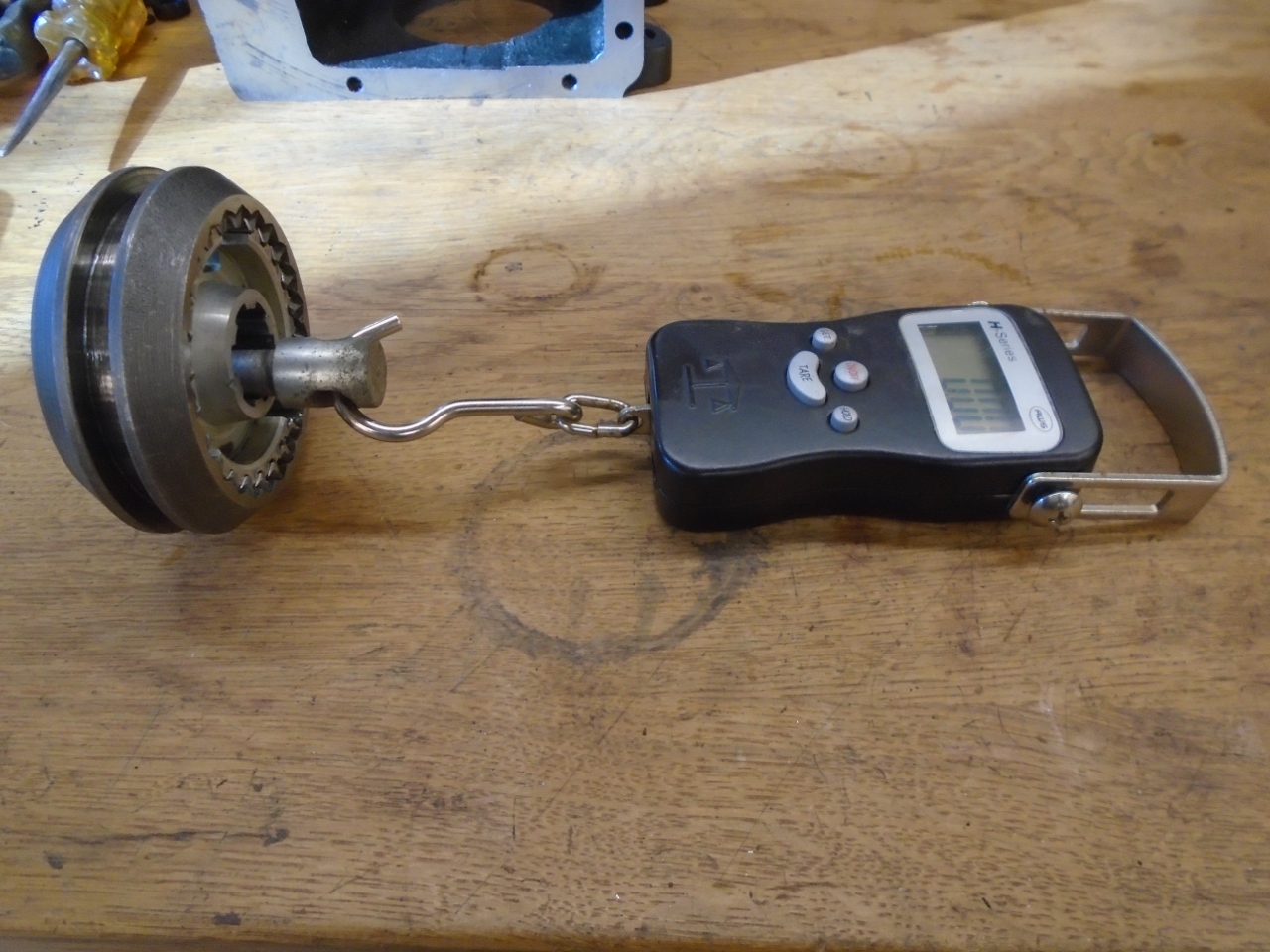
There
are a number of measurements mentioned in the manuals to determine if
anything needs to be replaced or adjusted. There are two
synchronizer assemblies, one for first and second gears, and the other
for third and fourth. They have spring loaded detents in their
central neutral position, and there is a spec for the amount of force
it should take to unseat the detent balls. Both of my
synchronizers took about 20 pounds, which is within spec.
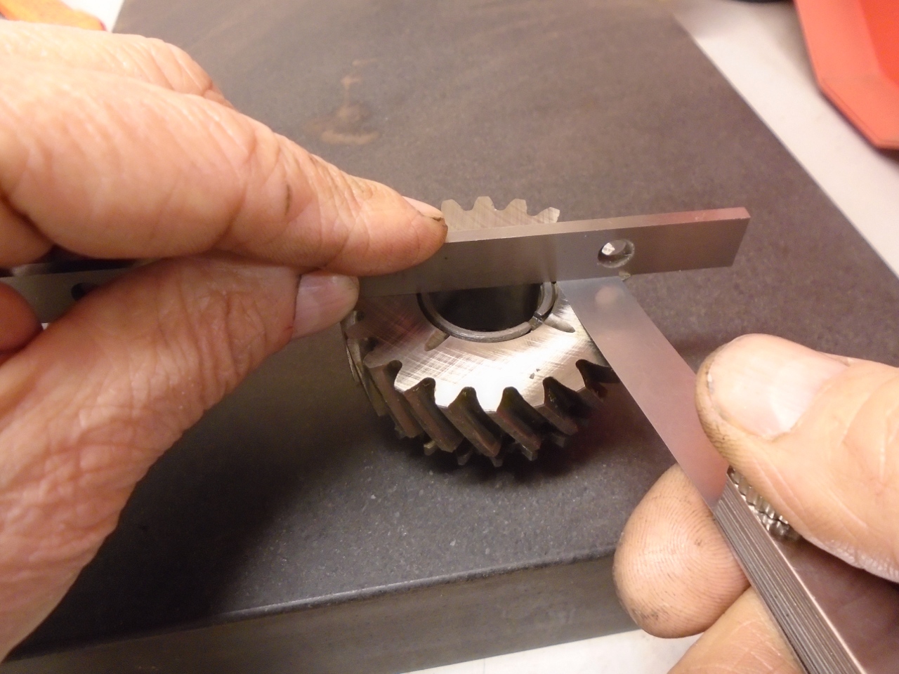
Next,
measurement of the end float of the 2nd and 3rd gears on their
bushings. This is done on a flat plate with feeler gauges. Mine came out at about 0.003, well within spec.
There
were a couple of other measurements on the mainshaft to do, and they
also came out within spec. So far, this gearbox appeared to have
very little wear.
At this point, I rounded up the reverse gear and shaft and put them in the case, mainly so they wouldn't walk away.

The
next job was to install the laygear cluster with it's thrust washers to
measure its endfloat. The laygear runs on 25 loose needle
bearings on each end. To keep them from going AWOL, a temporary
short layshaft has to be used to keep them contained. I made a
shaft from a length of 3/8" black iron pipe.
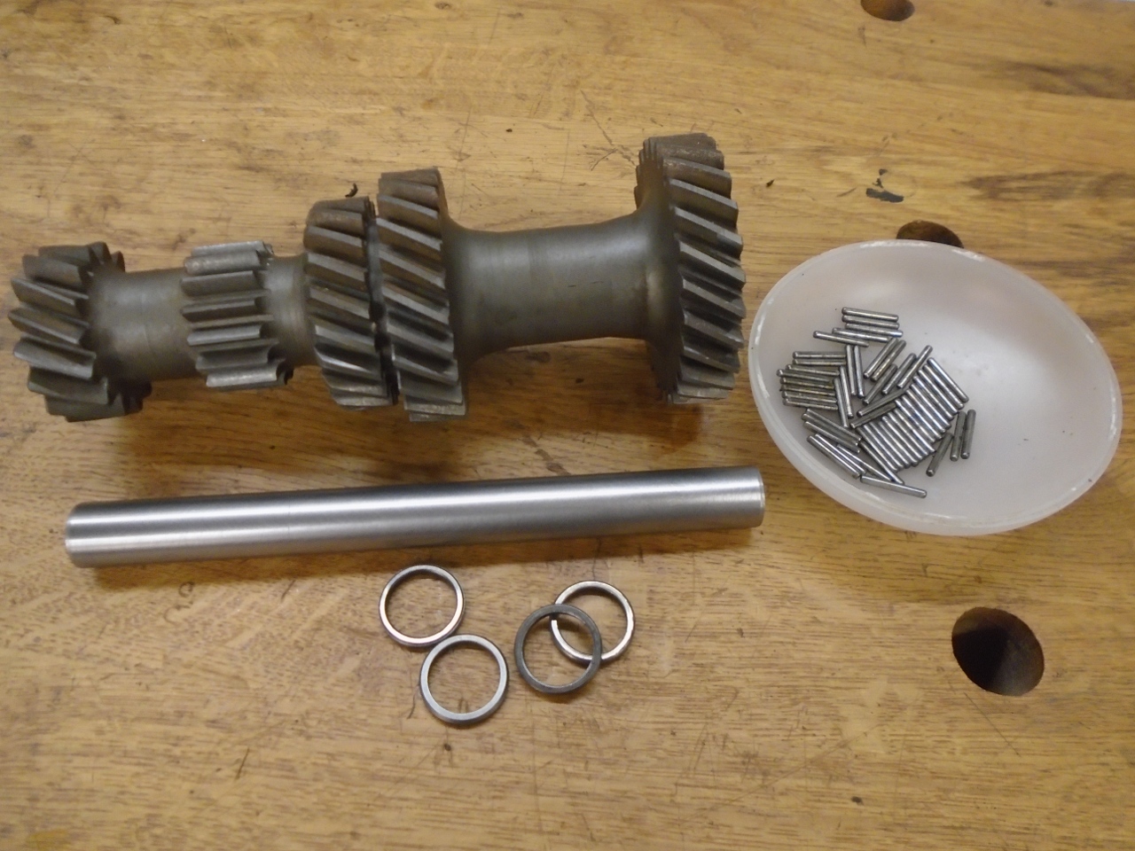
With
the laygear cluster in place with its two thrust washers, and the
temporary shaft replaced by the real one, I could measure the end
float. Again, it was within spec, so new thrust washers wouldn't
be necessary.
Then
the lay shaft was replaced by the shorter temporary one again.
This allows the laygear cluster to fall to the bottom of the
case, leaving room for the mainshaft to go in.
I
built up the mainshaft according to the manuals, and inserted it into
the case. Though the original bronze synch rings really looked
fine, I bought new ones. There seem to be two types available
from suppliers. Based on some sad stories I'd read, I got
the more expensive ones.
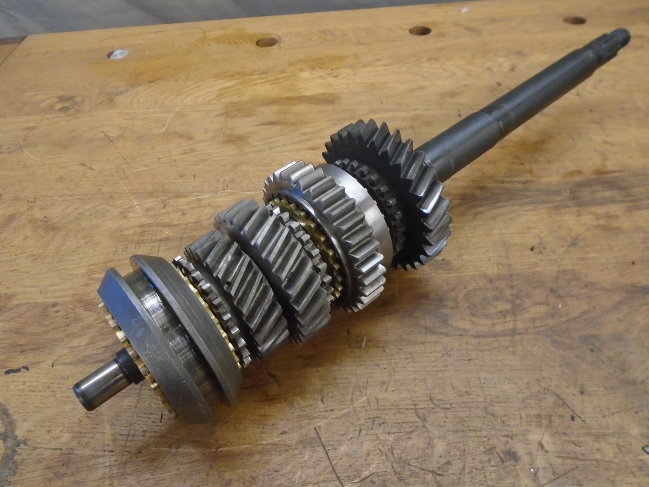

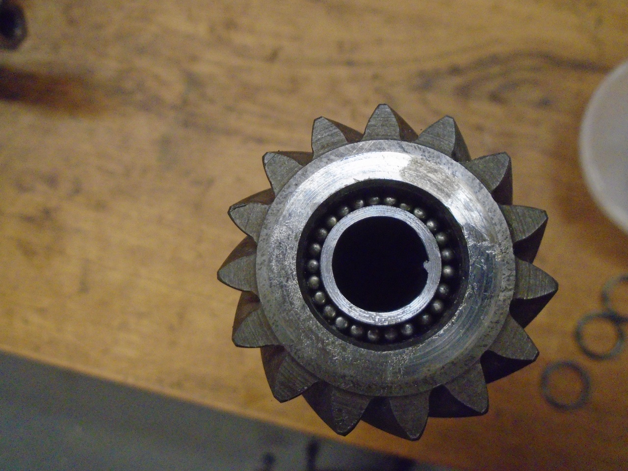
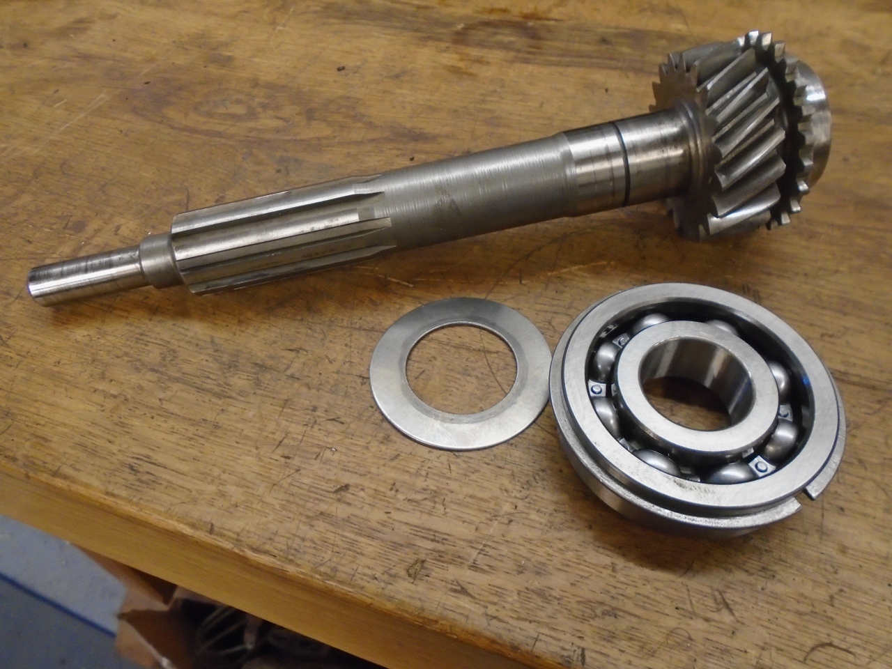
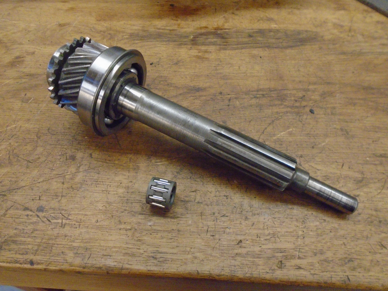
Then
I built the much simpler input shaft. With all of the wear
measurements so good, I probably could have just reinstalled the
original main bearings, but I had ordered new ones, so I used them.
That little caged roller bearing fits in the end of the input
shaft, and the nose of the main shaft goes into it.
So, now, with the main and input shafts and bearings all fully installed and rotating freely, I was home free.
Except.
When I rolled the case on its side, I heard a horrifying little
clink, and out fell this special little item onto the bench.
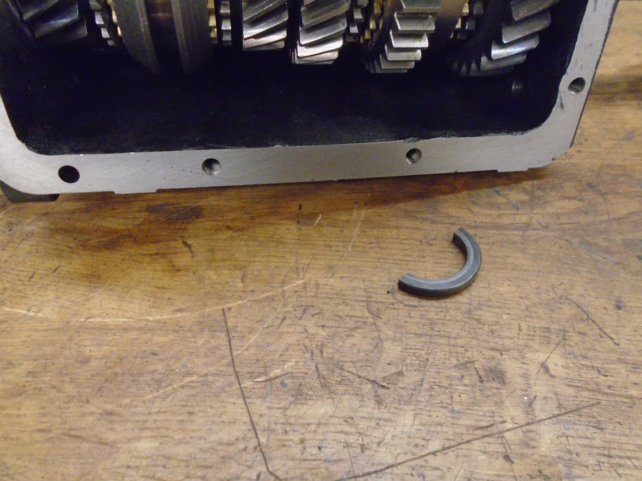
It's a split washer that was supposed to be deep within the mainshaft assembly.
So,
everything had to come out again to reinstall the split washer.
Finally got it back together, and turned the case upside down to
see what would fall out. Nothing. Silence. Beautiful!
Then,
while in the middle of my fifth or sixth fist pump, I caught the
glimmer of the shiny little fourth gear synch ring that should have
been installed with the input shaft.
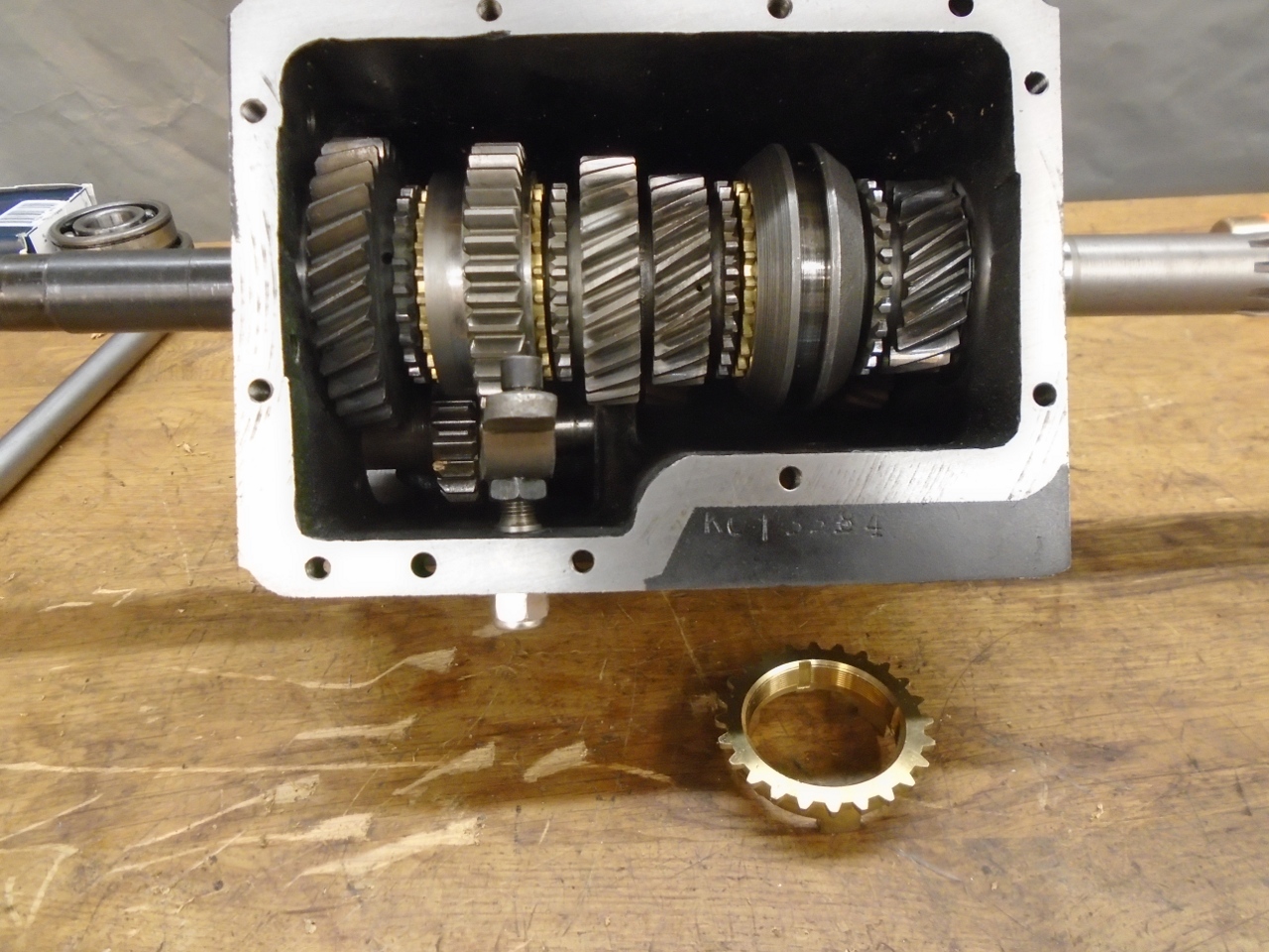
I
was relieved to realize that this part could be installed by only
removing the input shaft. I was getting pretty good at that.
OK,
so after scouring the bench and the surrounding floor for loose parts,
I finally decided that everything that is supposed to be in the case
was in there.
I
pulled the lay cluster gear up into mesh with the main and input
shafts, and used the layshaft to push out the temporary shaft. This is
when it is a good idea to make sure everything still turns like it
should, and that all of the gears work.
Lastly, I pushed on the spiral gear for the speedometer drive.
So,
here are all of the subassemblies ready for the mating ceremony.
Where I can, I replate and re-use the original hardware.

Bell housing and tailpiece on.
Gear selector and remote control.
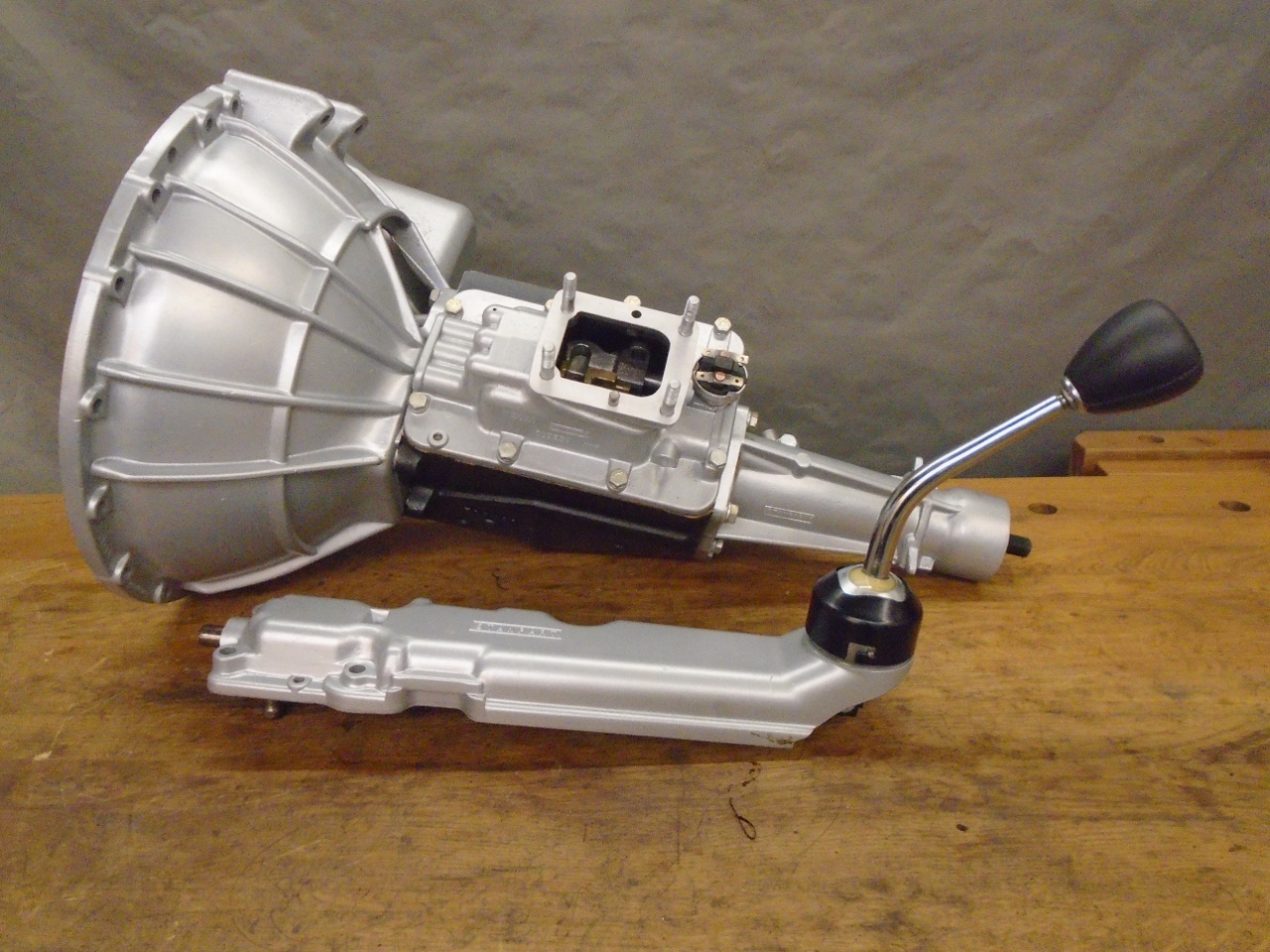
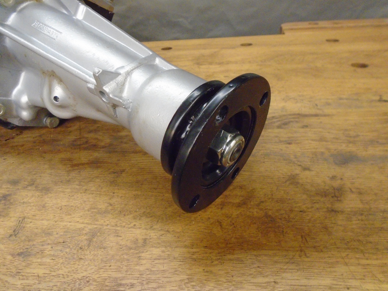
And finally, the drive flange.
I
checked out all the gears for proper and smooth operation, and am now
satisfied that the gearbox is probably together correctly.
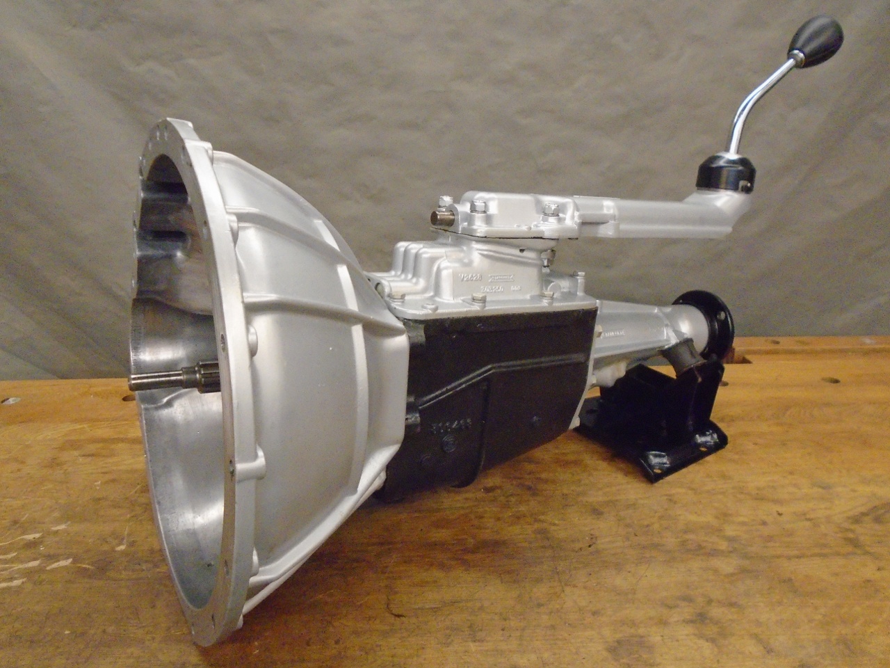
This
was sort of a harrowing project. I have done exactly one gearbox
before, and it hasn't really gotten any easier.
Though
in hindsight, and with the benefit of all the internal measurements, I
may not have had to replace much in this gearbox, I did replace the
bearings , seals, and synch rings, which came to something under $250
Comments to Ed at elhollin1@yahoo.com.
To my other GT6 pages.