To other pages.
Control Cables
[Click on pictures for a better view]
Buying all new control cables (not speedo and tach) for the bike would apparently run around $200. Having promised Bonnie I would try to keep costs under control, I looked into building the cables myself. Once common, this isn't done too much any more, but a web search turned up a few places that still sell the components, and it looked like I could save quite a bit by starting from scratch. This would also allow a little customization of lengths, placement of adjusters and the like, but except for the brake cable, I reallty just duplicated what was on the bike.
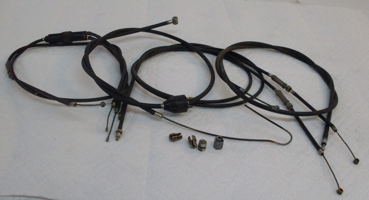
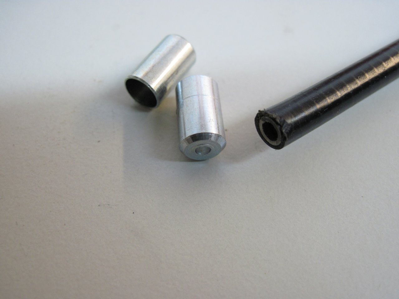
The basic components of a control cable are the flexible wire conduit, the inner wire, and various ends and fittings. The conduit I got was wound with rectangular-section wire, so it is relatively smooth inside and out. The flat wire also makes the conduit thinner so there is room for a nylon liner for reduced friction and less wear. The conduit is cut to size with a hack saw, the ends squared and cleaned up, and end ferrules are applied. Sometimes a friction fit of the ferrule wasn't enough, so I used a little super glue to keep them in place. The inner wire is standard stranded steel wire-rope--0.064" for the lighter duty throttle and choke, and 0.080" for the clutch and brake. The wire is terminated typically by attaching small wire ends. The wire ends are usually brass, and commonly soldered onto the wire. There must be other metyhods of attachment, though, because in trying to get some of the old wire ends off, they melted before they let go. Maybe thery were crimped or even cast on.

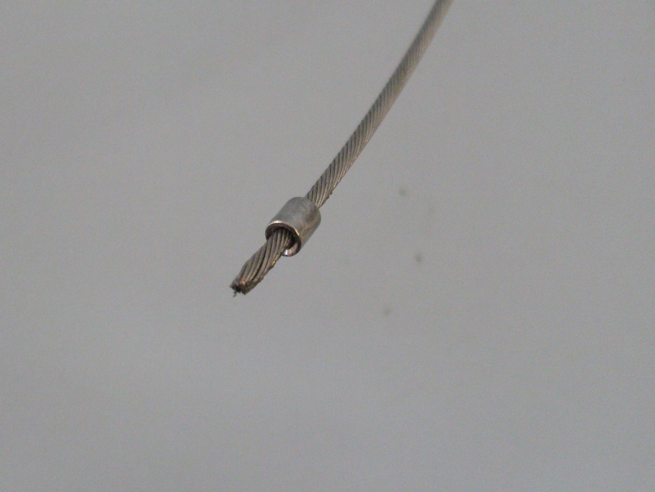
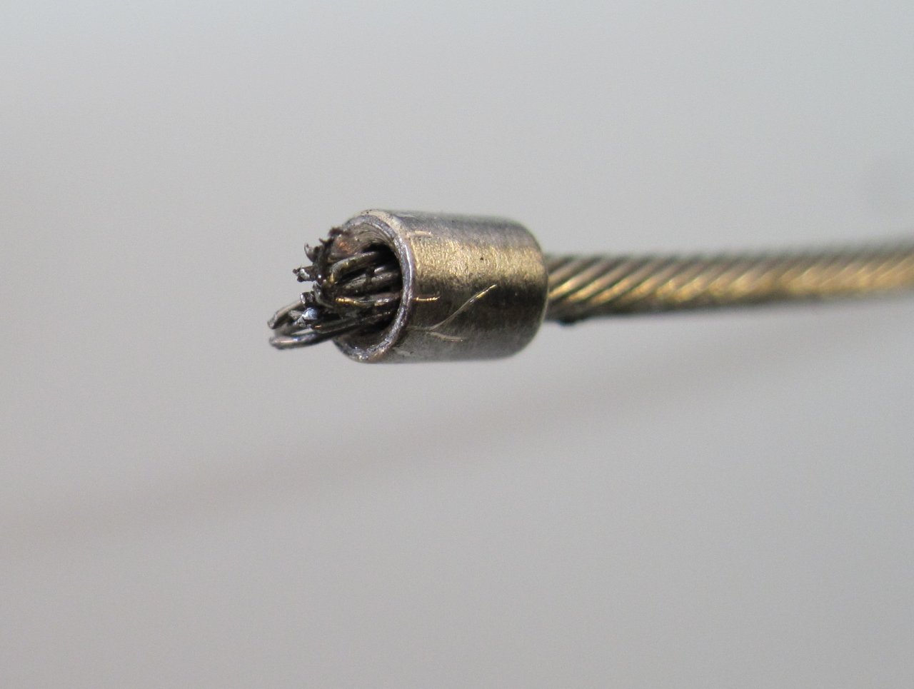
To solder the wire end on, first notice that one end of the wire end must have a chamfer or counterbore. This end goes toward the end of the wire. The strands of the wire are then "upset", or spread out into the chamfer or counterbore. This way, when the recess of the wire end is filled with solder, there is more than just the shear strength of the solder joint holding the end on.
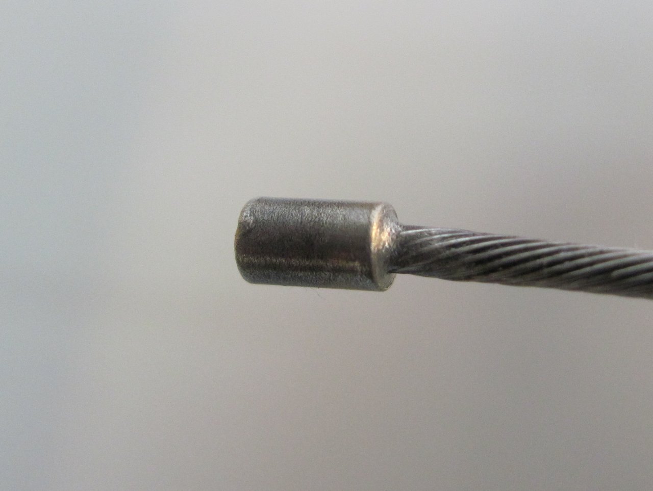
Soldering steel can be tricky, but the process I used was to tin the wire first using a non-acid 50/50 solder paste and a small butane pencil torch. I then applied the end, spread the strands, and used a little more solder paste to hold everythong in place. I then heated the end and applied some Sn96/Ag4 (that's 96% tin, 4% silver) solder to fill the joint. You know the joint is filled correctly when you see the nice solder fillet on the back side of the end. It's important, though, not to let solder wick too far down the wire. This makes it stiff and more prone to breaking with flexing.
The silver-bearing solder is very strong for soft solder. It is not, however, the same thing as true "silver solder", which requires a temperature high enough to affect the strength of the wire.

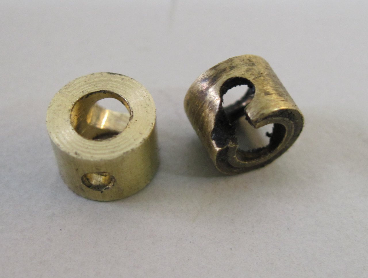
These are the little brass fittings that the soldered wire end slips into so that it can attach to the throttle twist grip. The one on the right was damaged, the left one was made from a piece of 1/4" brass rod.
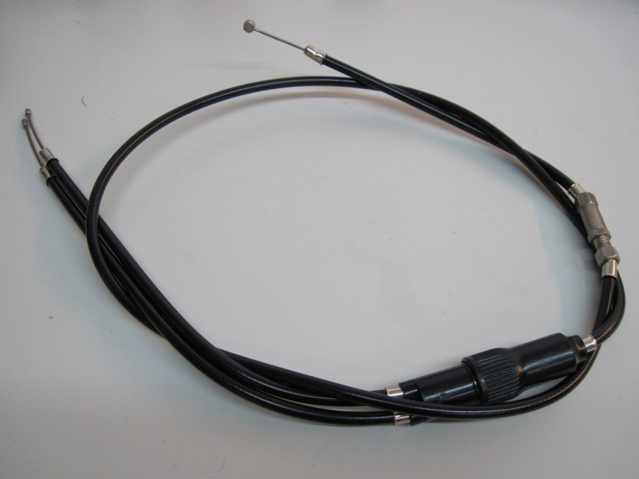
The finished throttle cables. I re-used the stainless steel adjusters and the adaptors on the carb end.
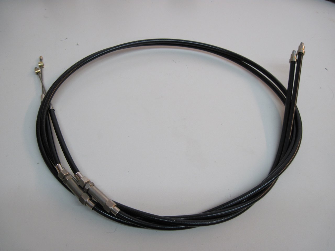
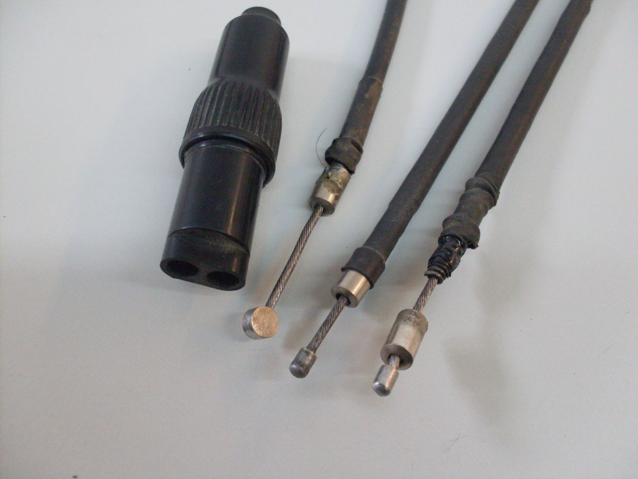
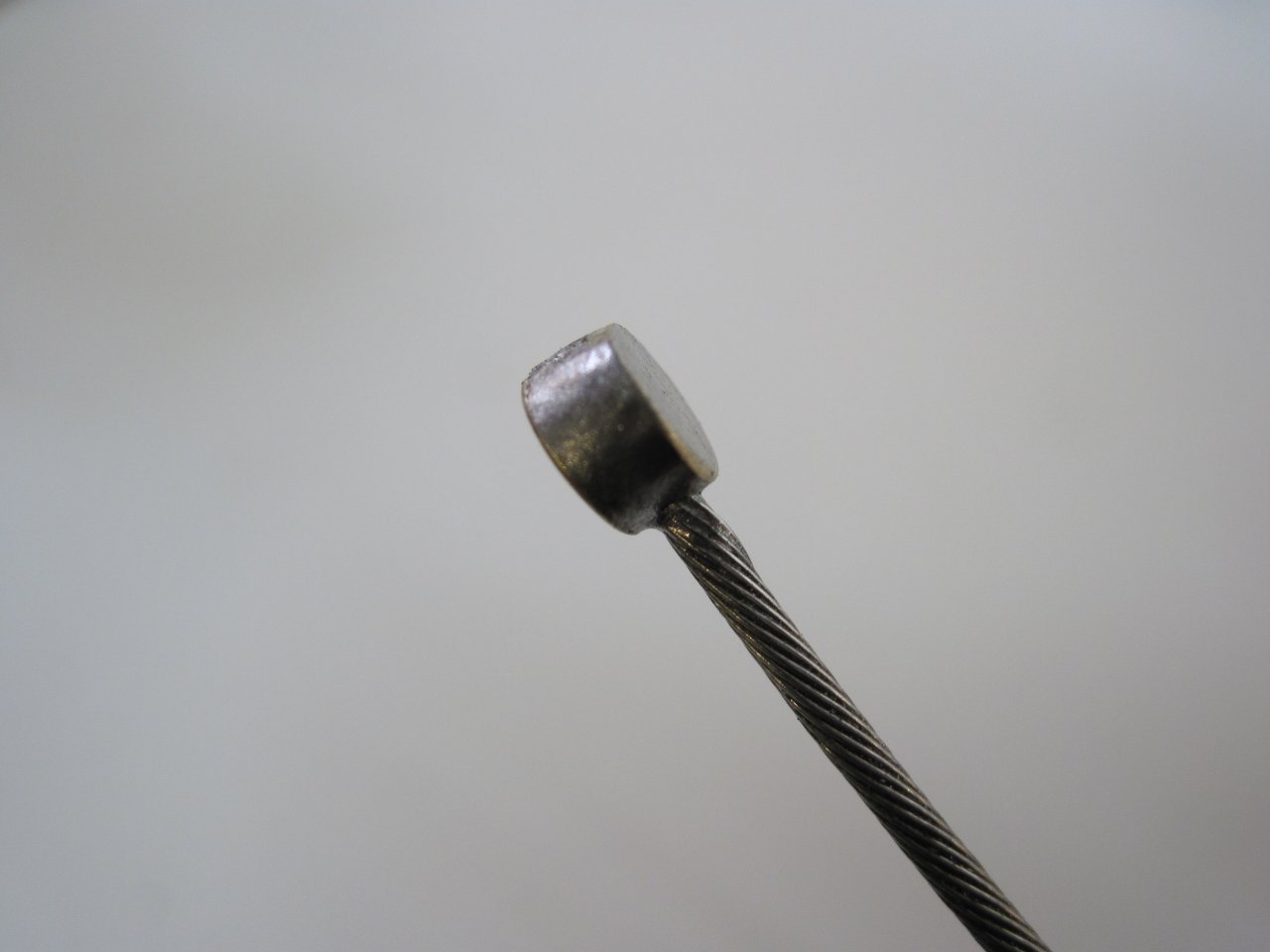
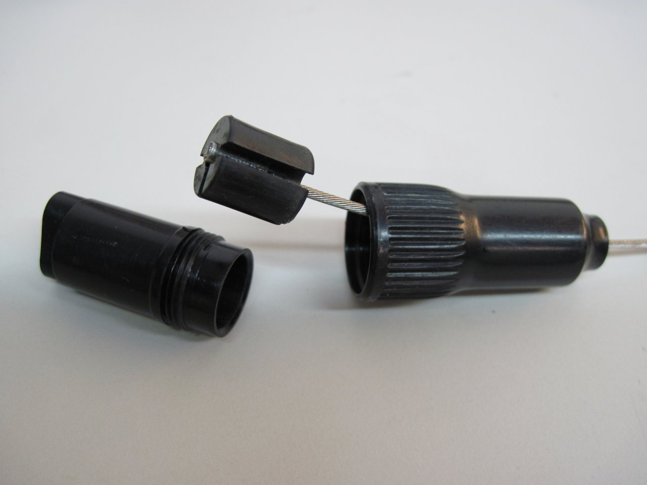
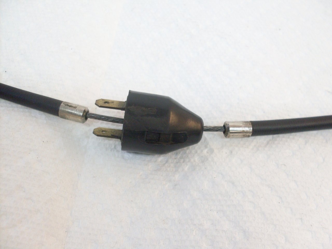
The choke cable is built similarly. The soldered-on end at the handle bar control end is a flat disk instead of the tiny cylinder like on the throttle cables. There is also the plastic junction box where a single cable pulls cables to each carb.
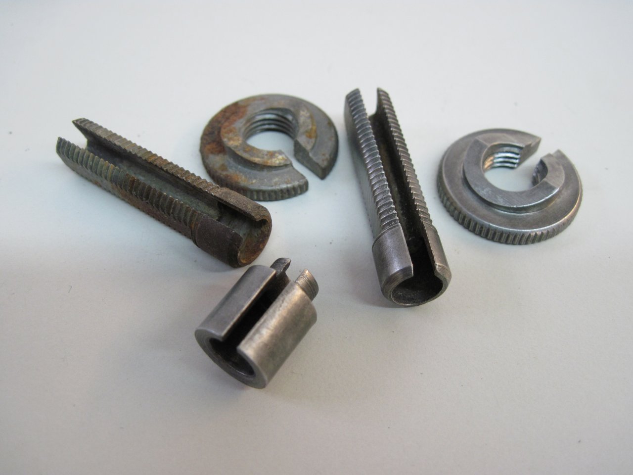
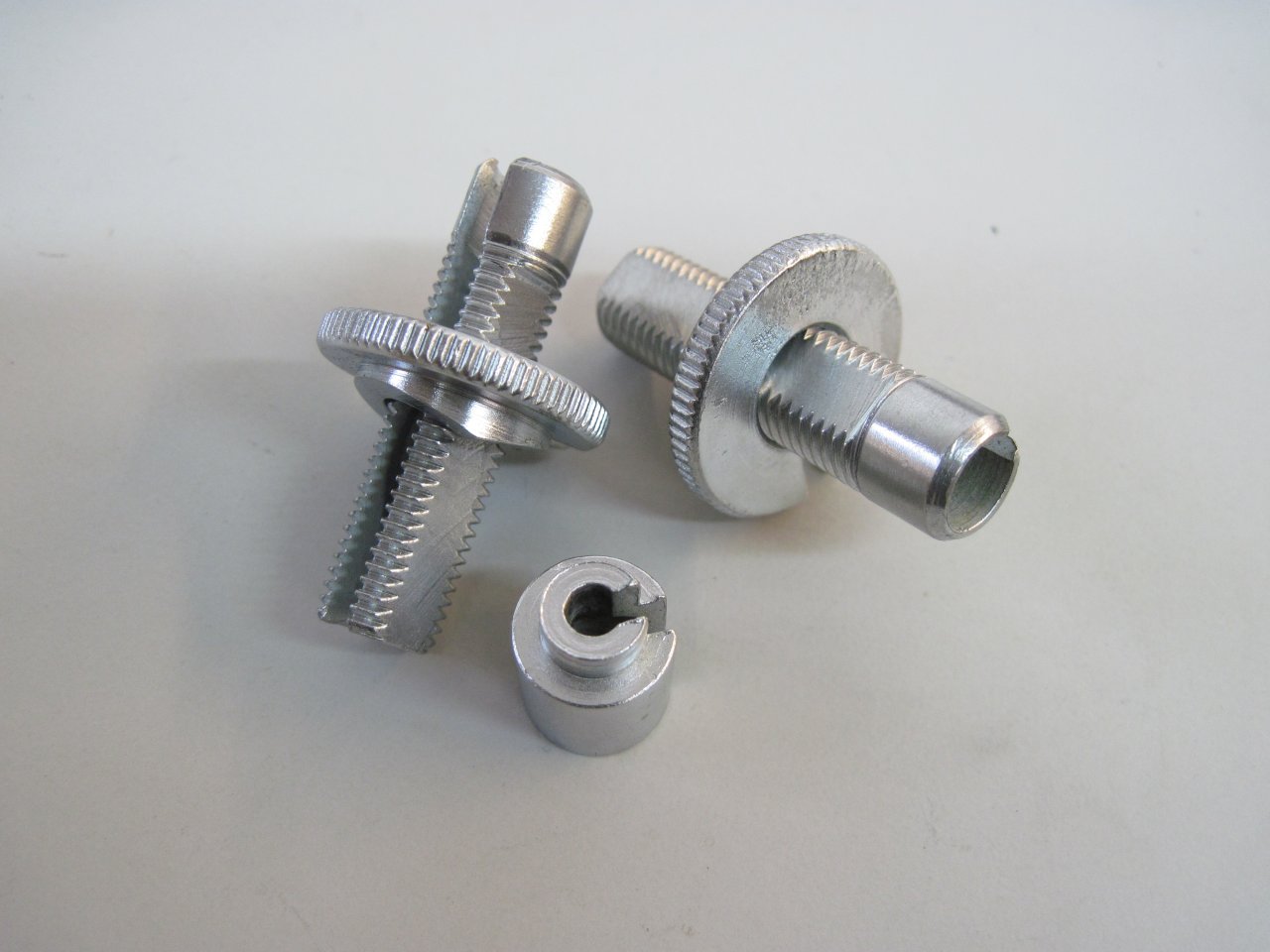
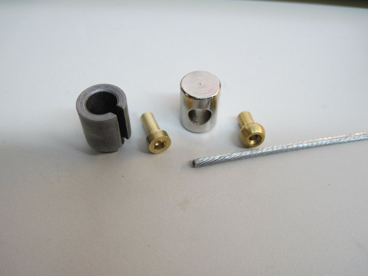
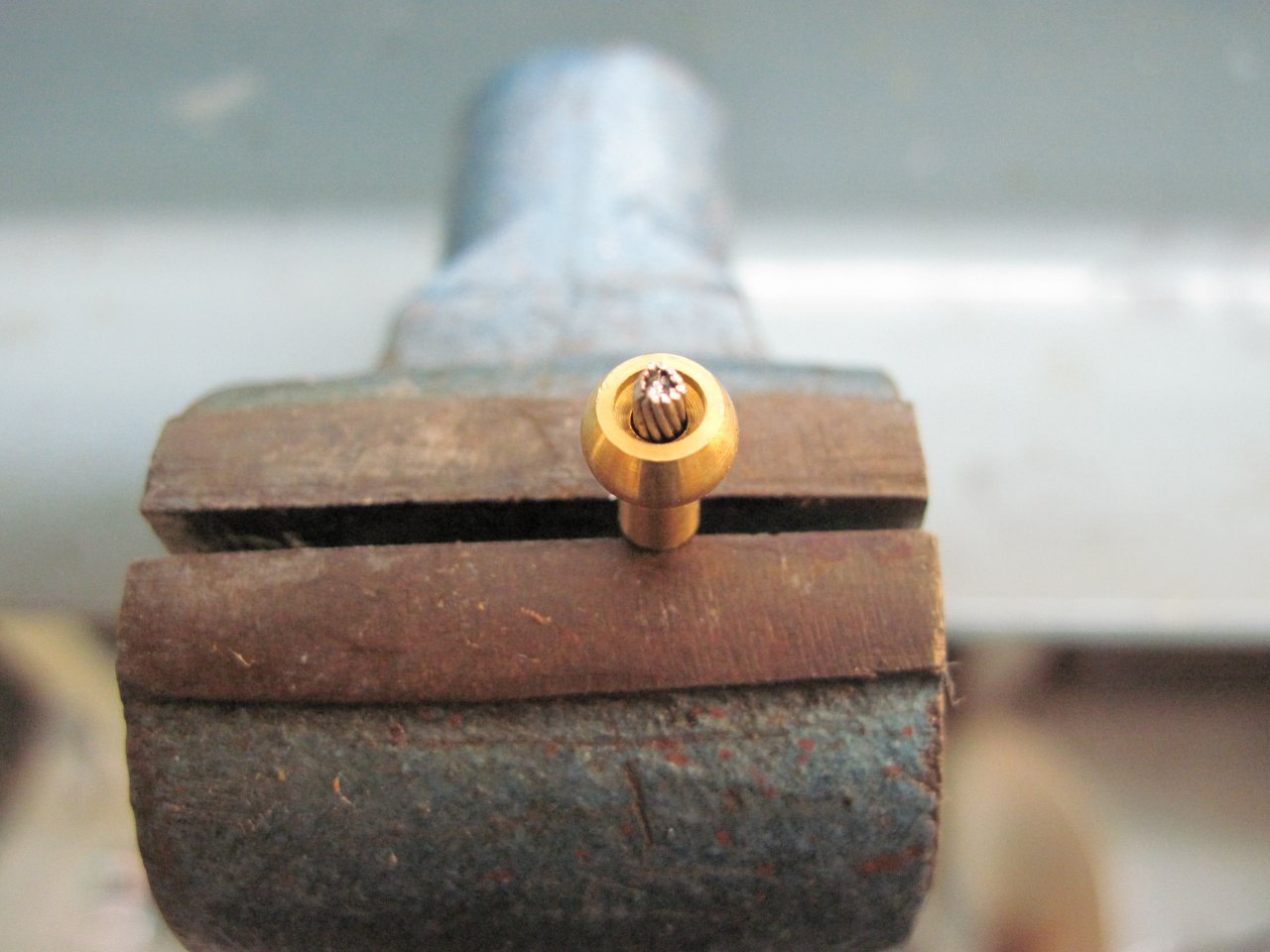
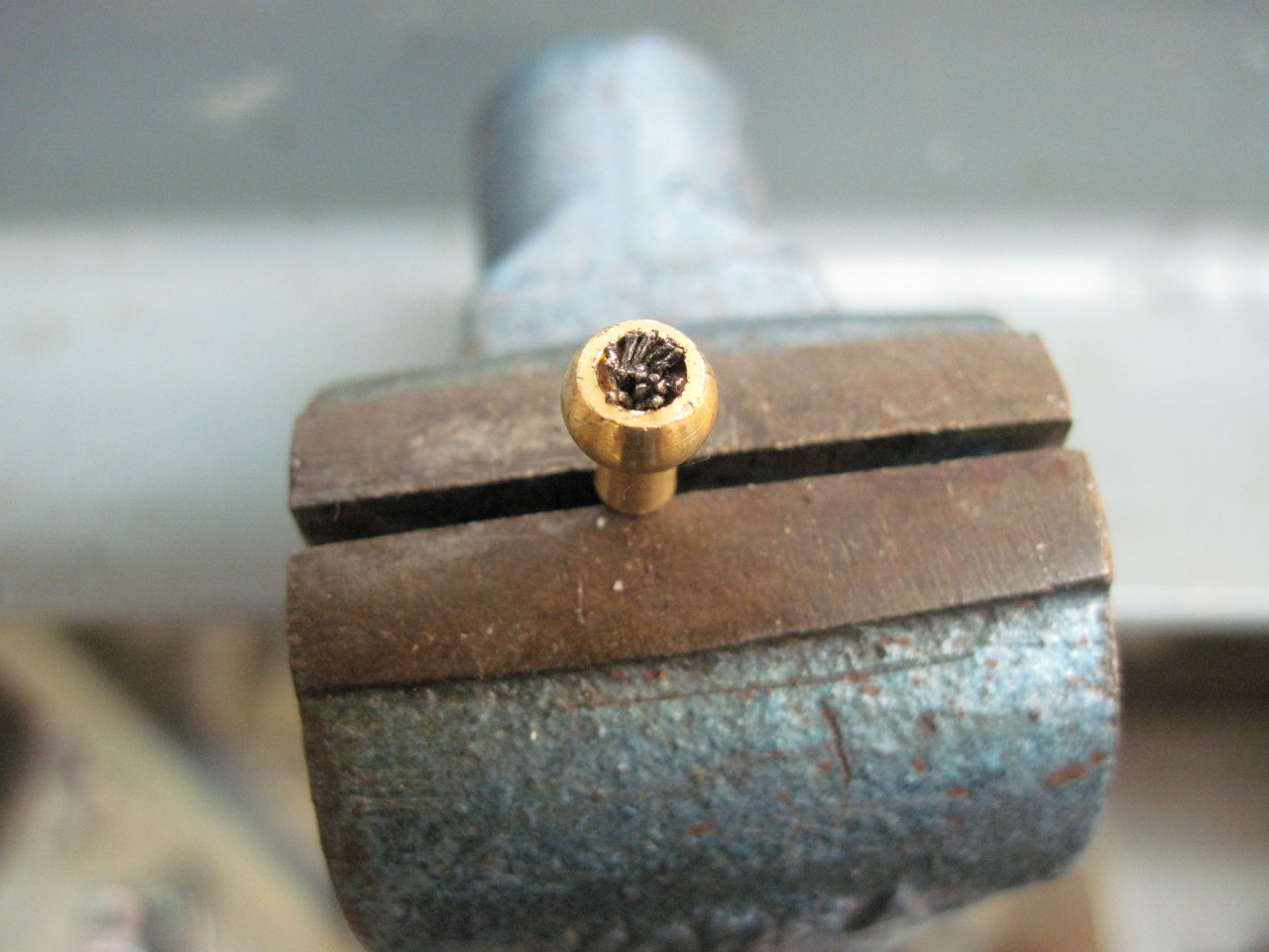
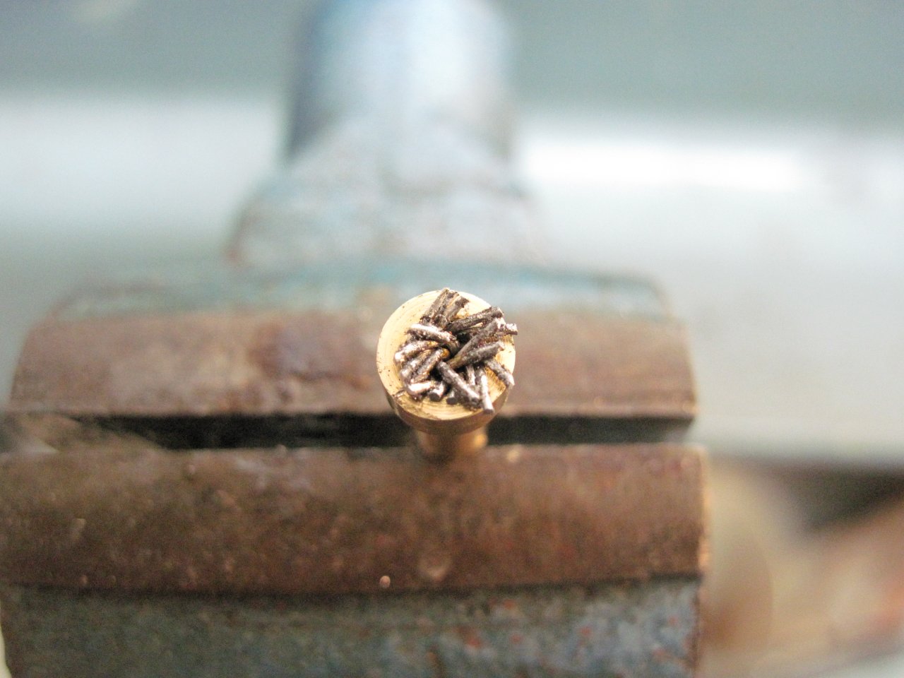
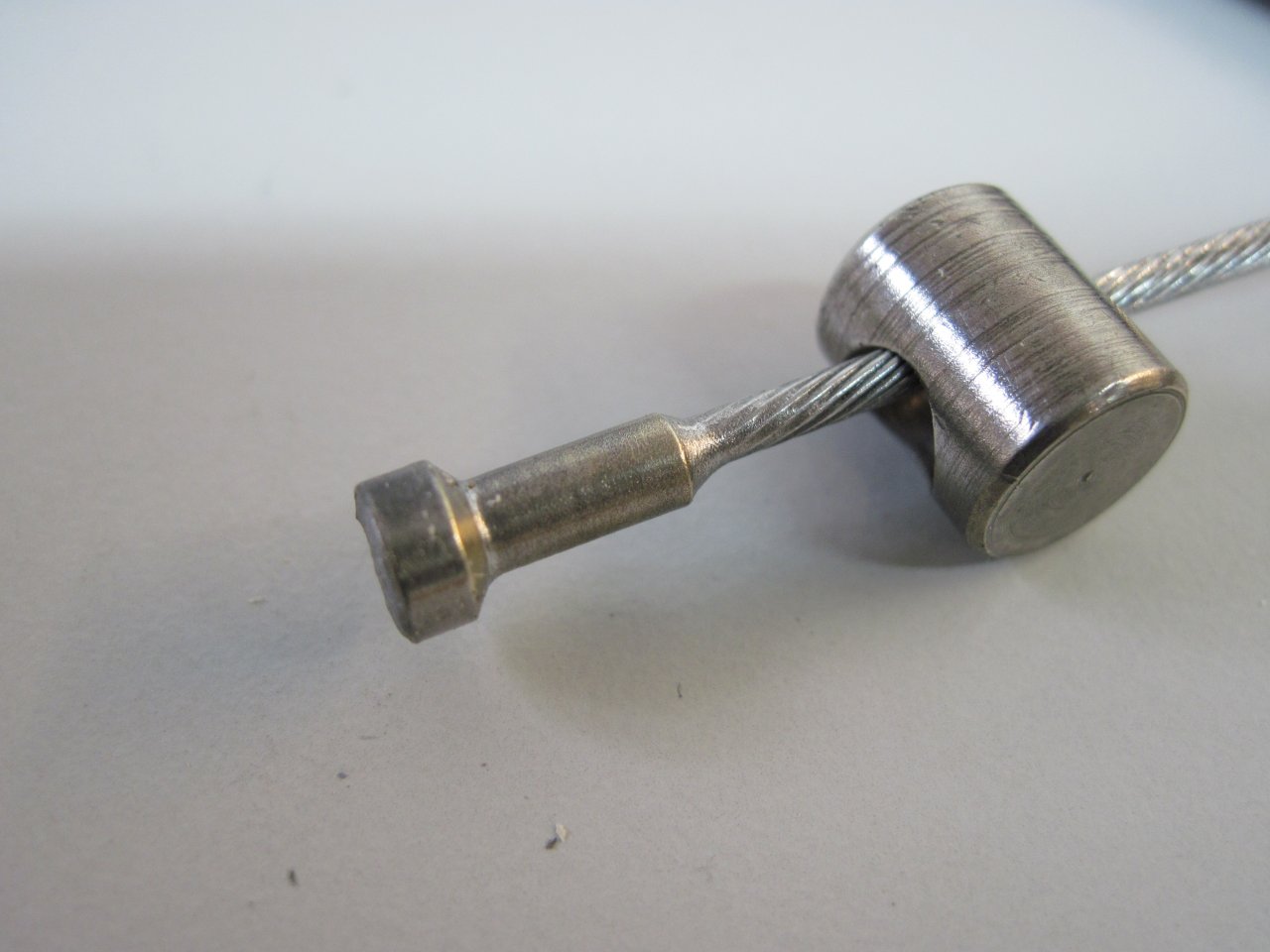
The clutch cable was actually in decent shape, but I decided to make a new one anyway, saving the old one for a spare. The left picture shows the fittings. The brass ball on the right goes on the gearbox end. The other brass fitting solders to the wire, and fits in the barrel on the hand control. The other pictures show the ball end in preparation for soldering.
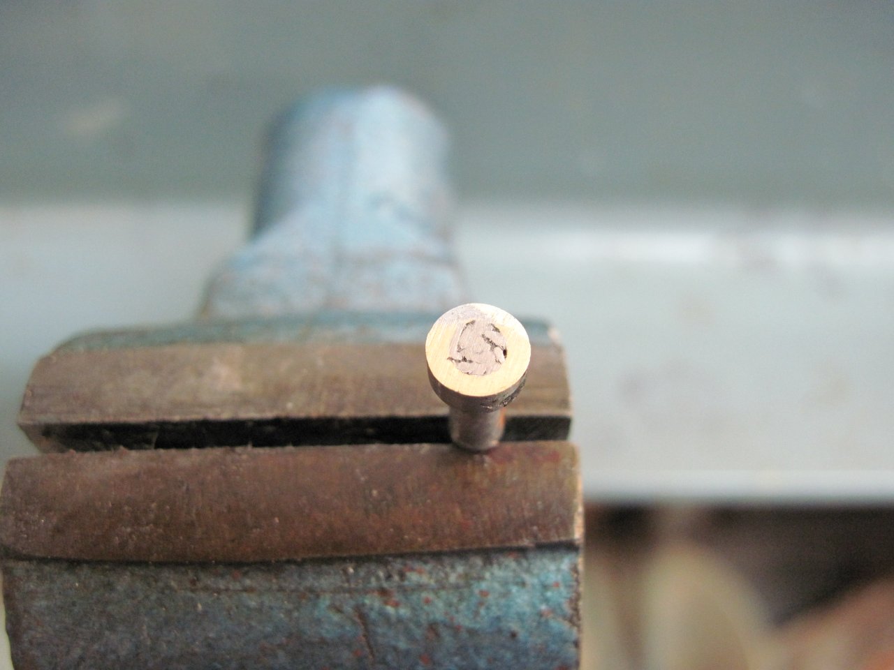
This is how the handle bar end goes together. After soldering the mess of peened wire stands, I grind the top flat for a neater appearence.
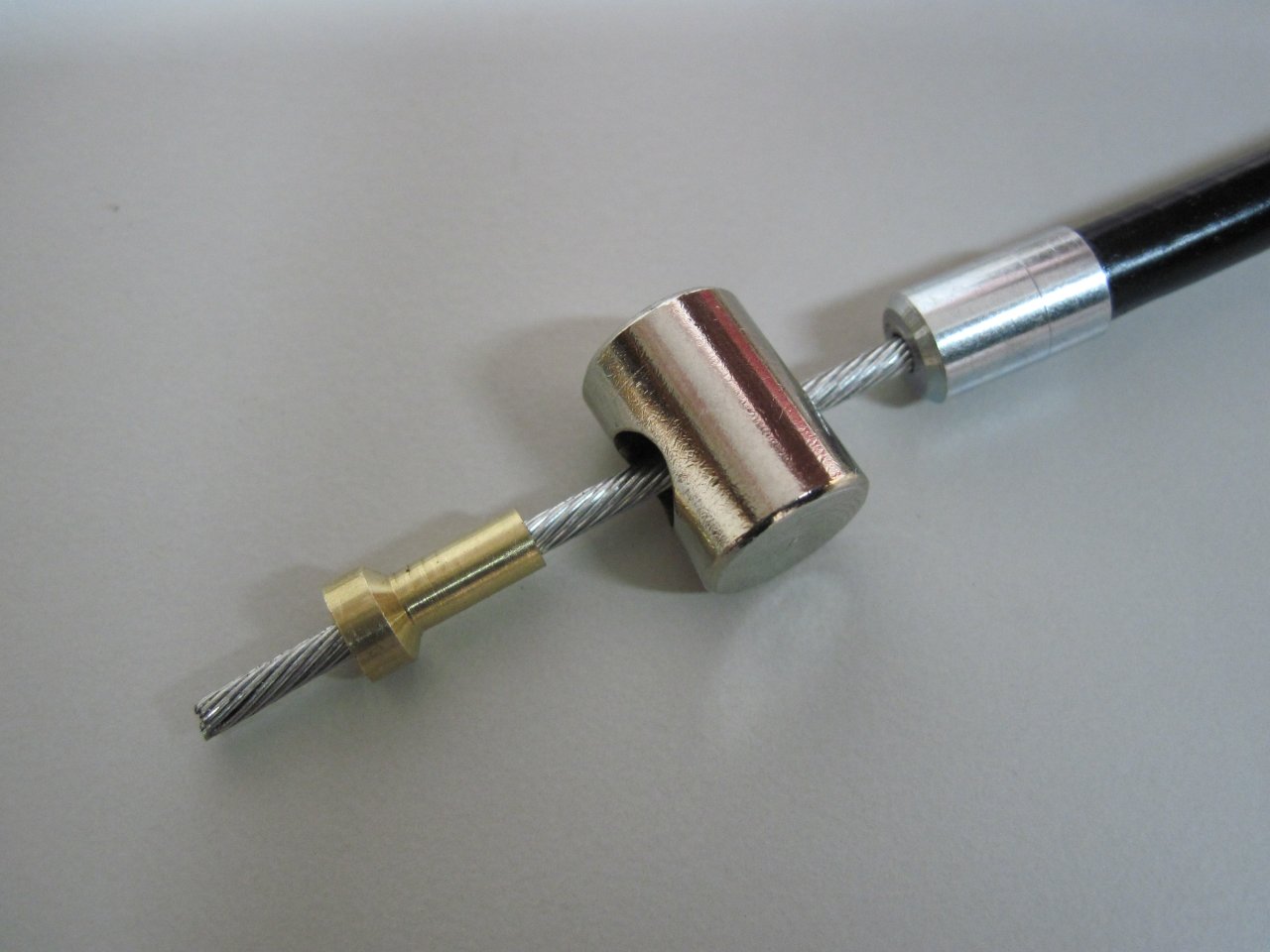
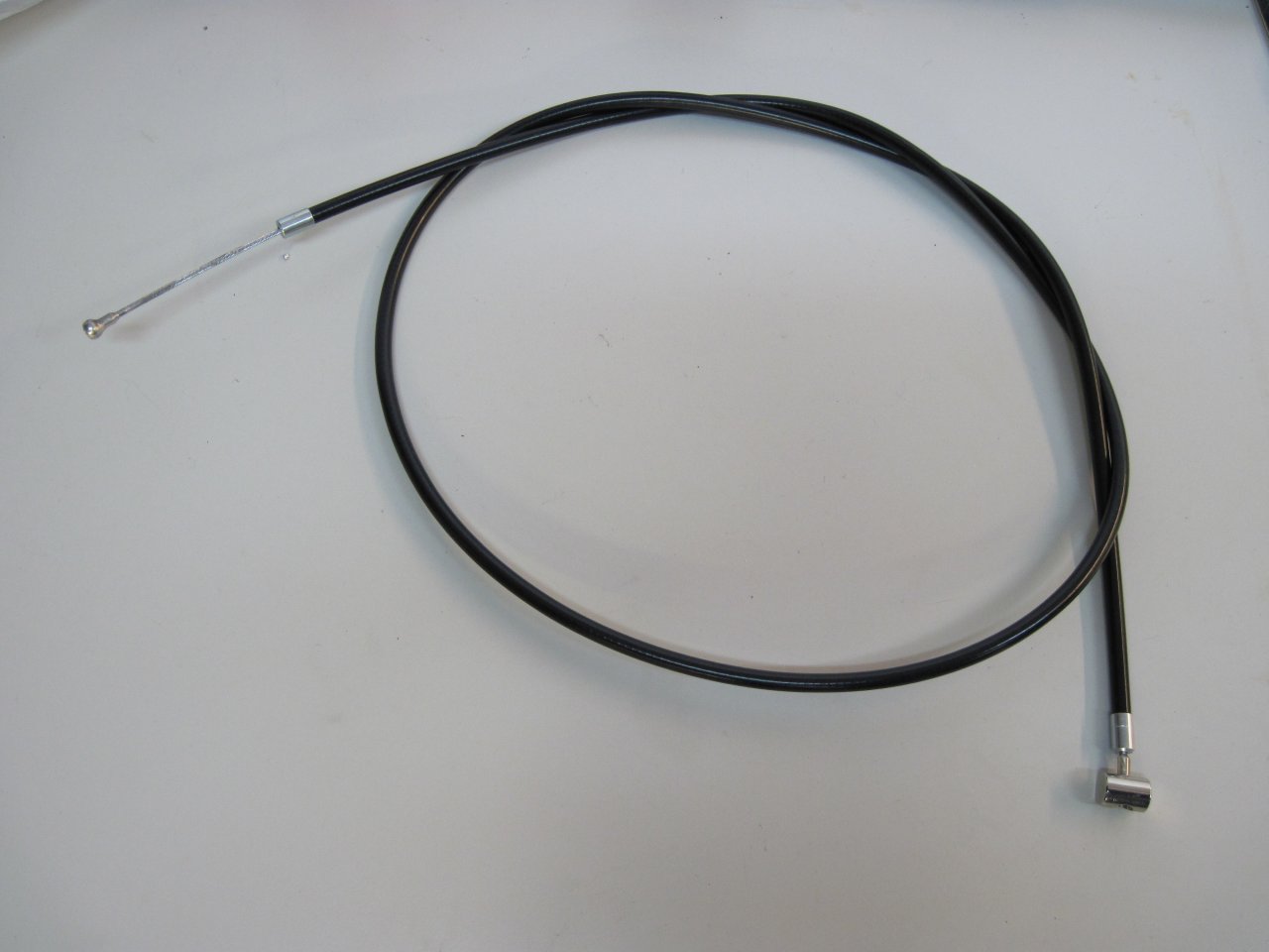
The finished clutch cable:
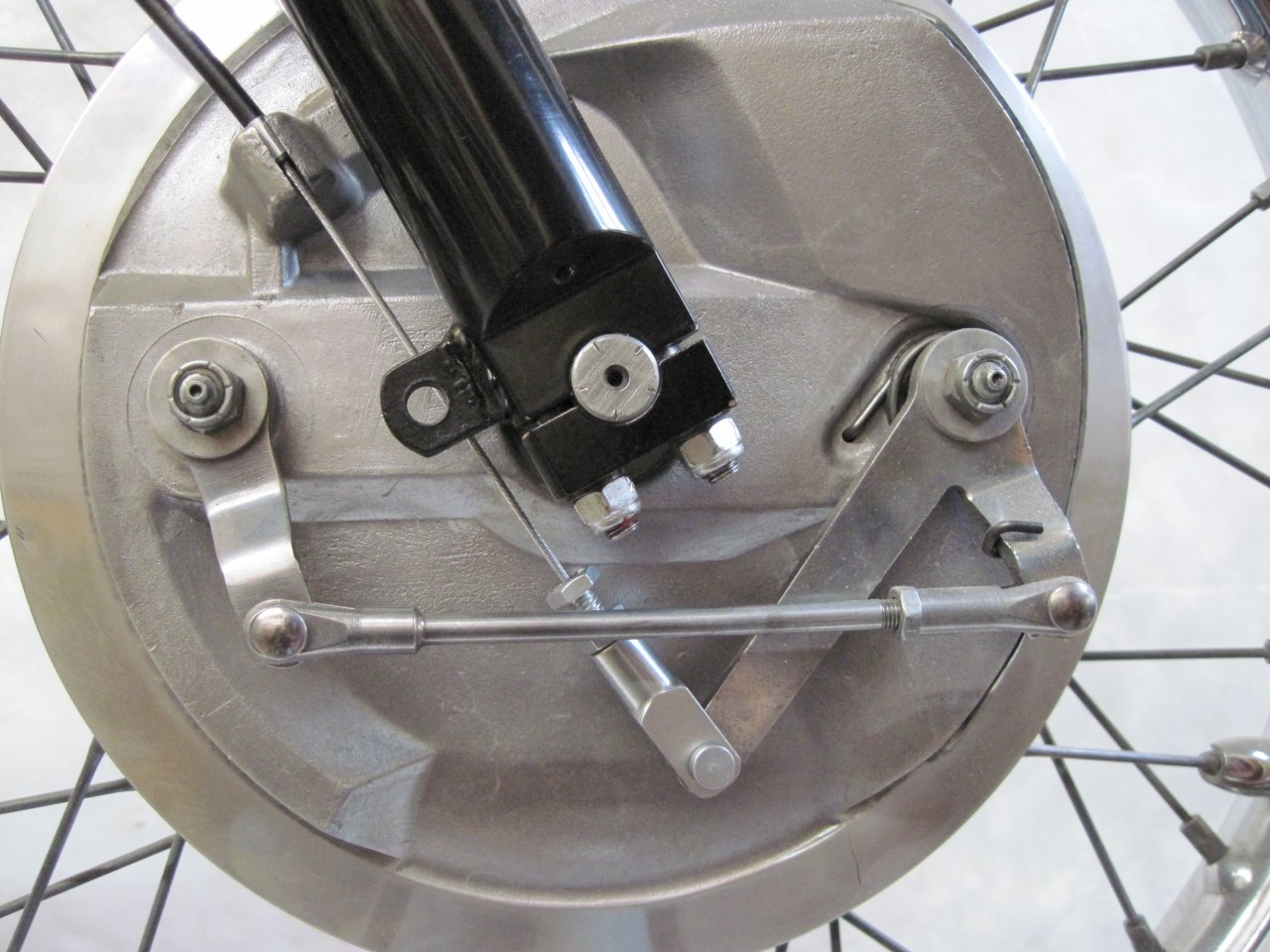
The front brake cable was definitely not original. It appeared to be some kind of universal replacement because there was no yoke fitting at the brake end--only a clamp arrangement that allowed adjusting the inner wire length.
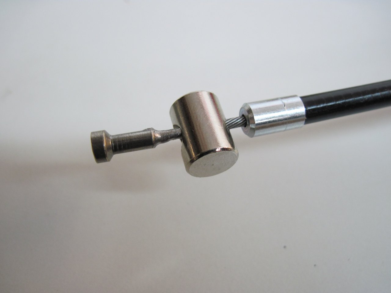
Here is the handlebar end with the barrel that slips into the brake lever, and the front brakelight switch. The switch apparently works by compressing a rubber washer enough for some contacts to touch. I thought it was bad at first, but just wasn't using enough force.
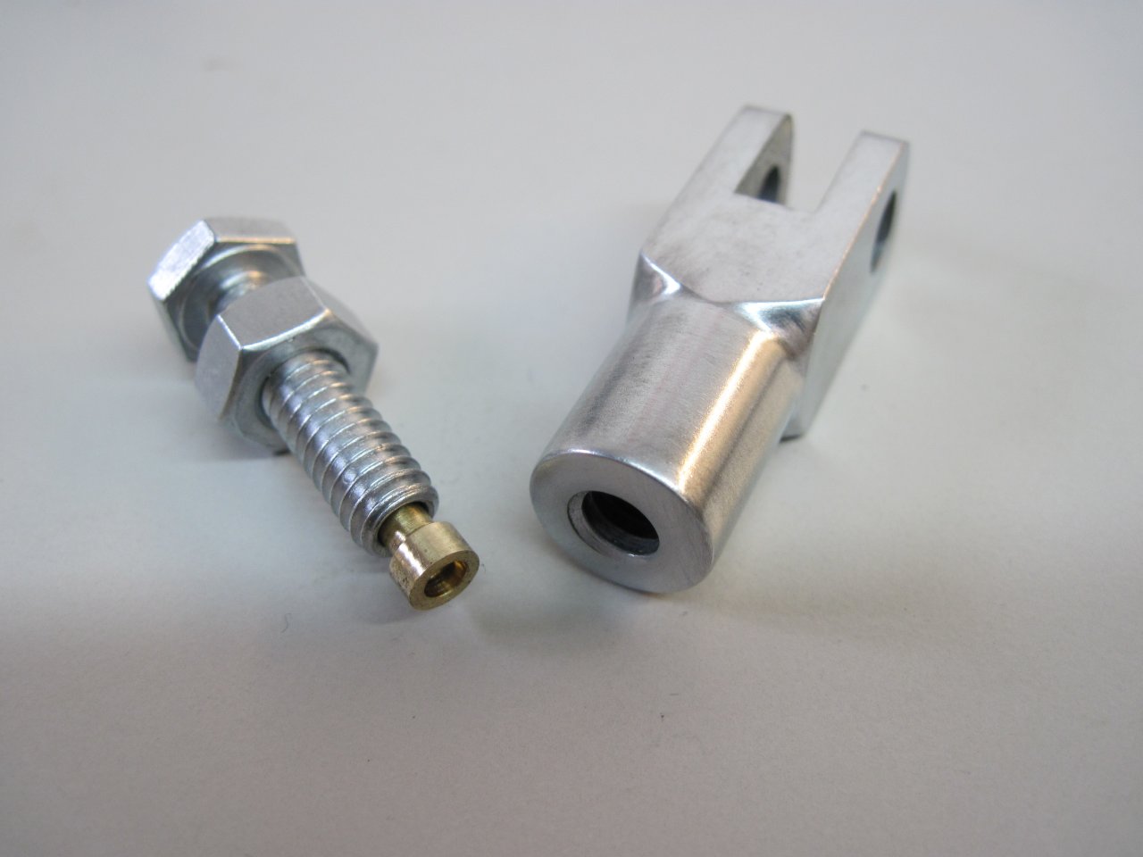
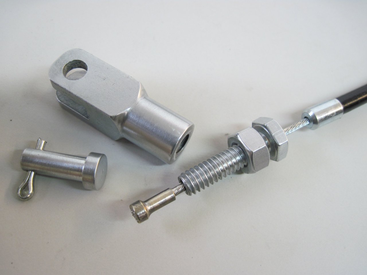
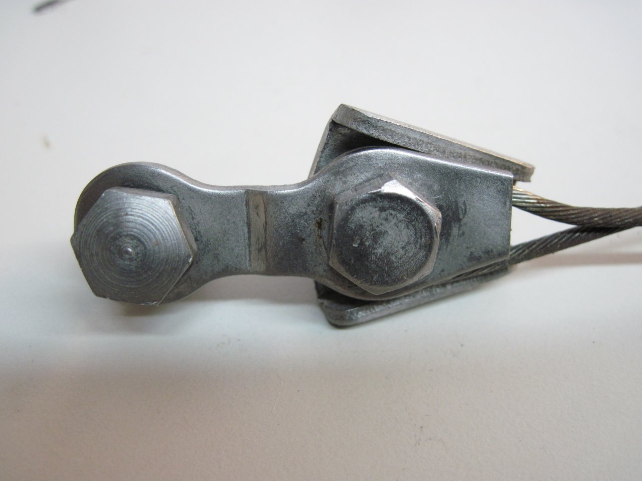
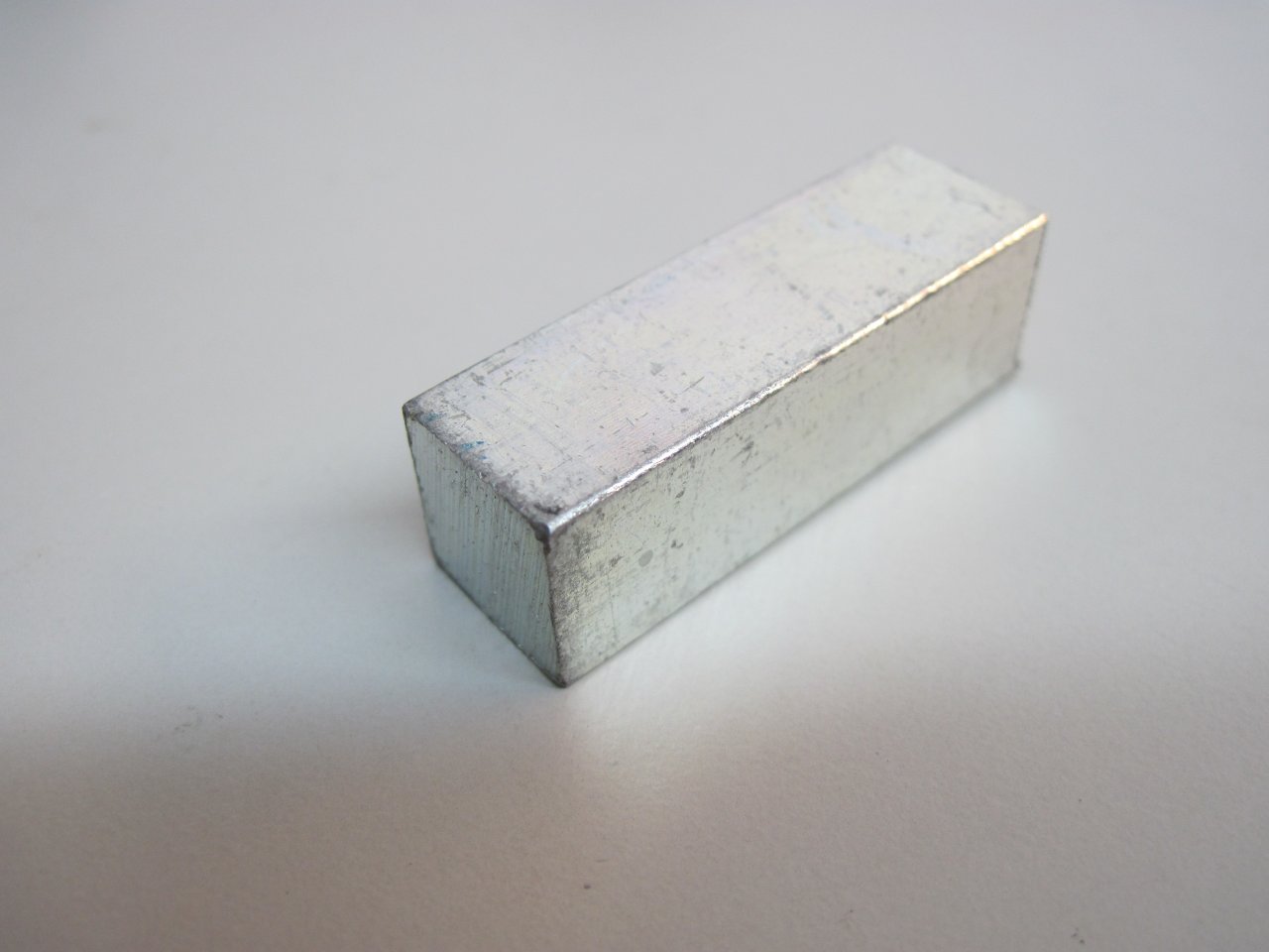
I made a yoke for the brake end, starting from a hunk of 1/2" key stock.
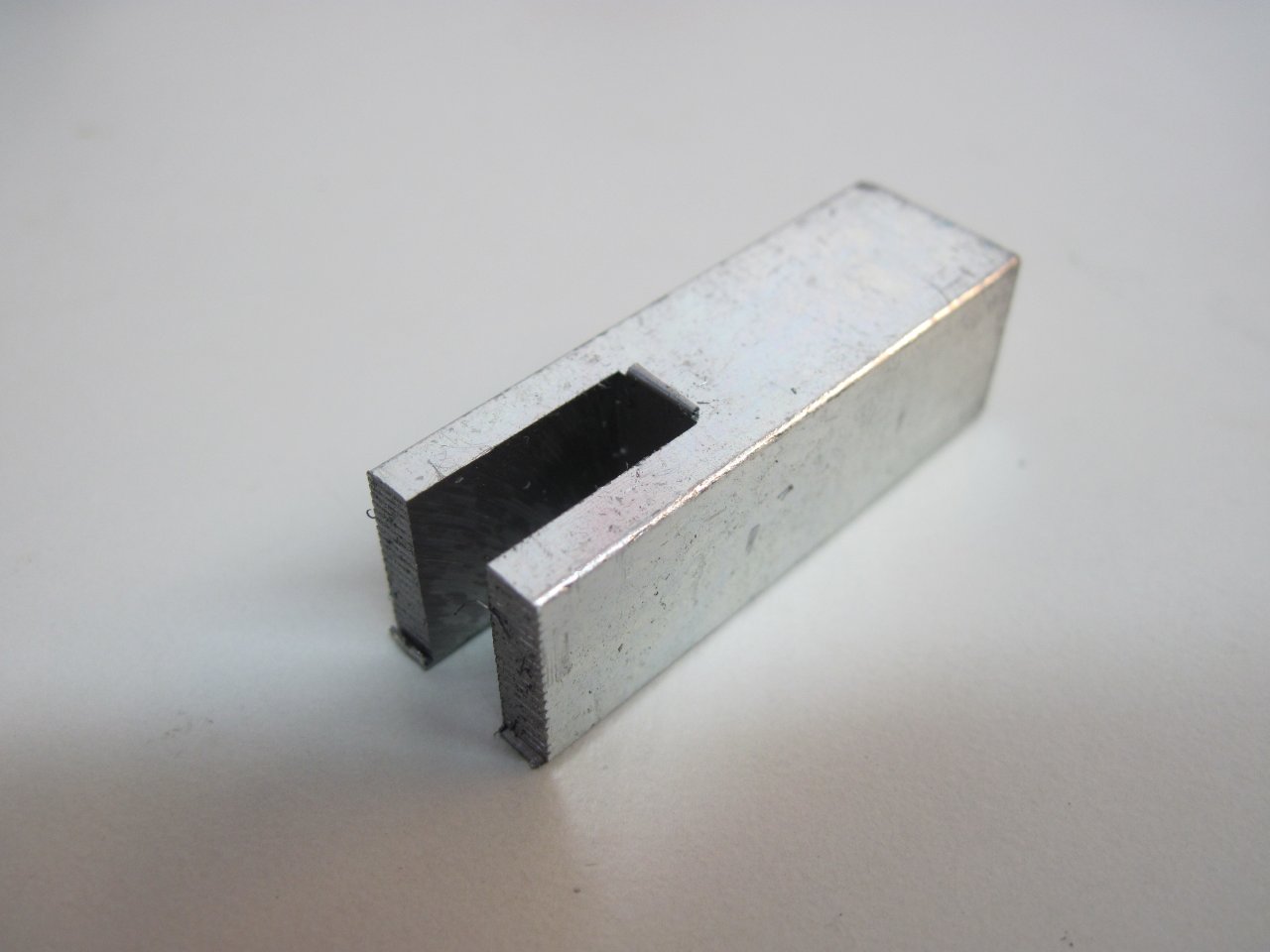
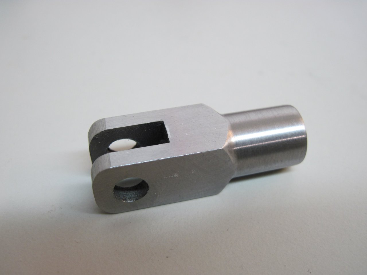
The new yoke will provide another place to adjust the brake control. I zinc plated the steel parts for some weather resistace. I know I've got some 1/4" clevis pins around, but after looking for half an hour, it seemed quicker to just make one.