To my other TR6 Pages
June 12, 2017
Dash Support
[Click the pics for a better view]
TR6
cars have a cast aluminum dash support structure that straddles the
gearbox and spans between the lower lip of the dash and the frame.
The cross section of the support is pretty beefy, suggesting it
is more than just a place to hang the radio. The support acts
essentially as an X-brace, adding side-to-side rigidity to the dash and
cowl area of the body. It also keeps the dash from flapping in
the breeze.
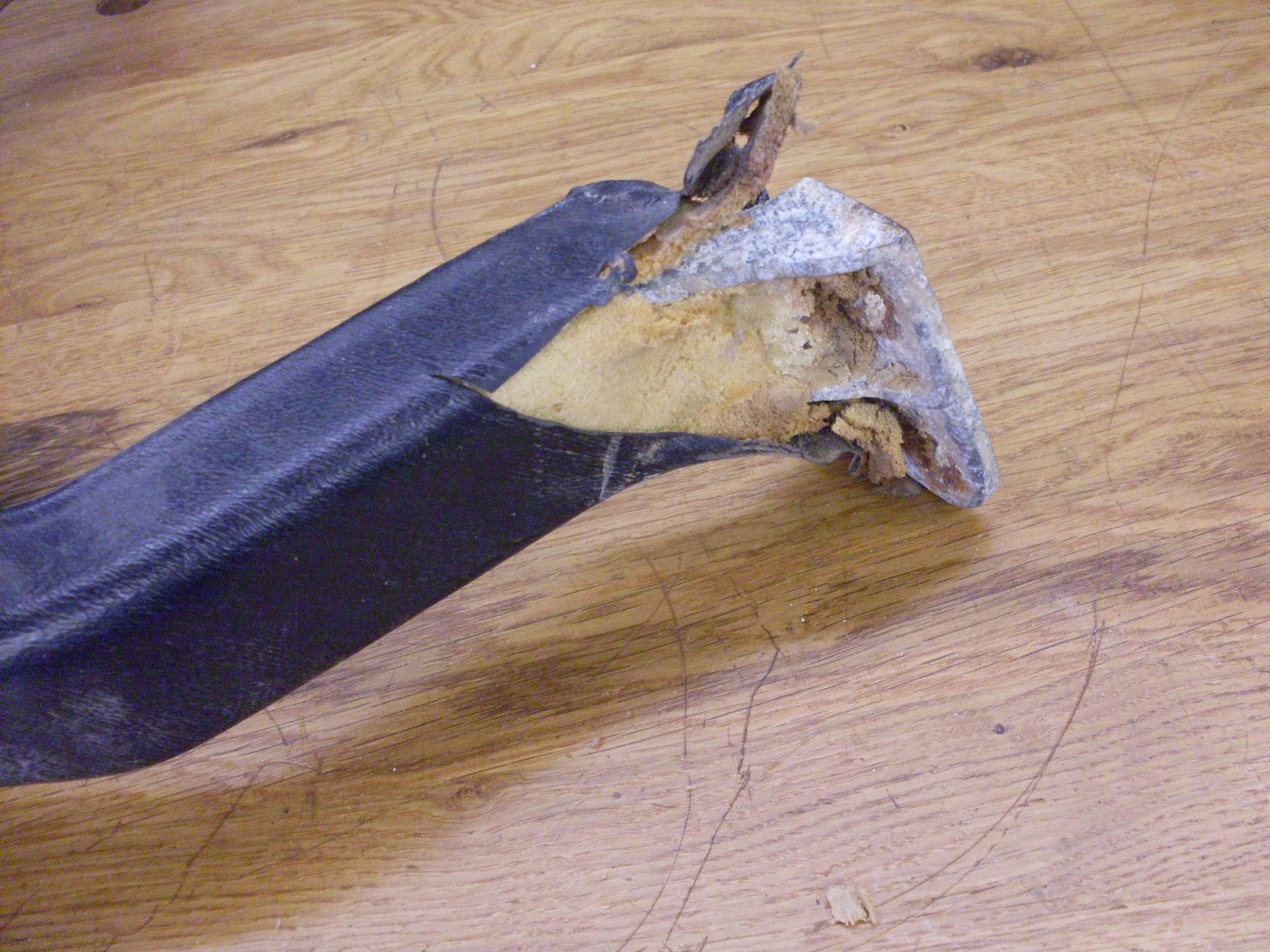
My
support was corroded in places, but structurally sound. The vinyl
cover however, was beat up beyond saving. It's not too hard to
separate the vinyl/foam covering from the casting.


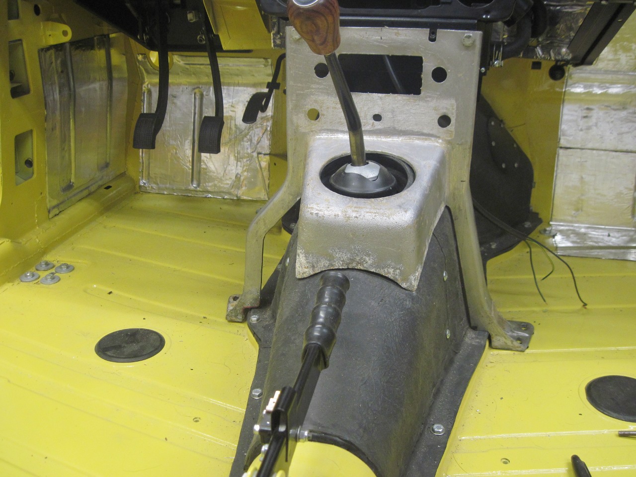
When I made my fiberglass transmission tunnel,
I sort of streamlined it, removing some of the unnecessary
bumps, warts, and other protuberences. I knew at the time
that this would likely require some mods to the support. A test
fit confirmed that the awkward dog-leg on the driver's side of the
support was no longer necessary, and in fact, I'd gain a couple of
inches of knee room by removing it.
My
first thought was to just modify the stock support, but I cringe at the
notion of cutting into a perfectly good 43-year-old original part.
Beside that, I had a few ideas about how a new center console
might tie into the support, so I stepped back to reconsider. In
the end, I decided to just make a new support, and preserve the
original in case it didn't work out.
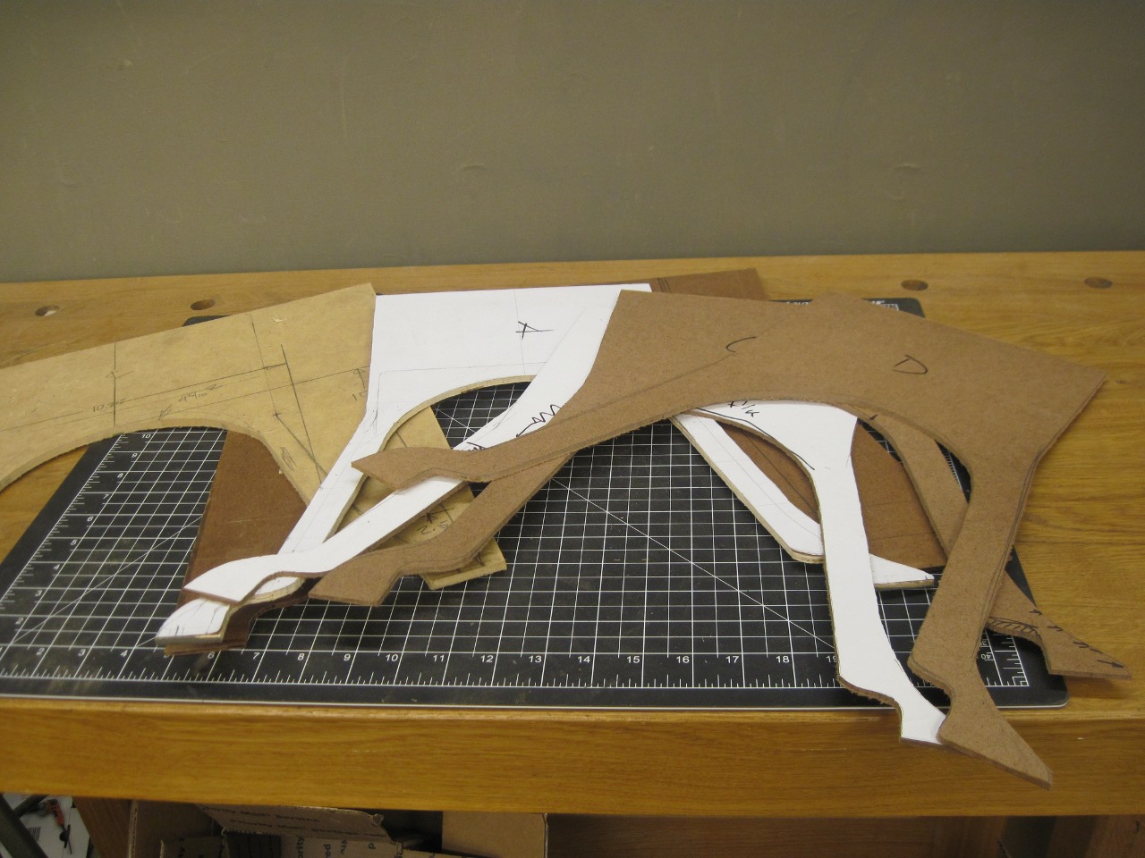
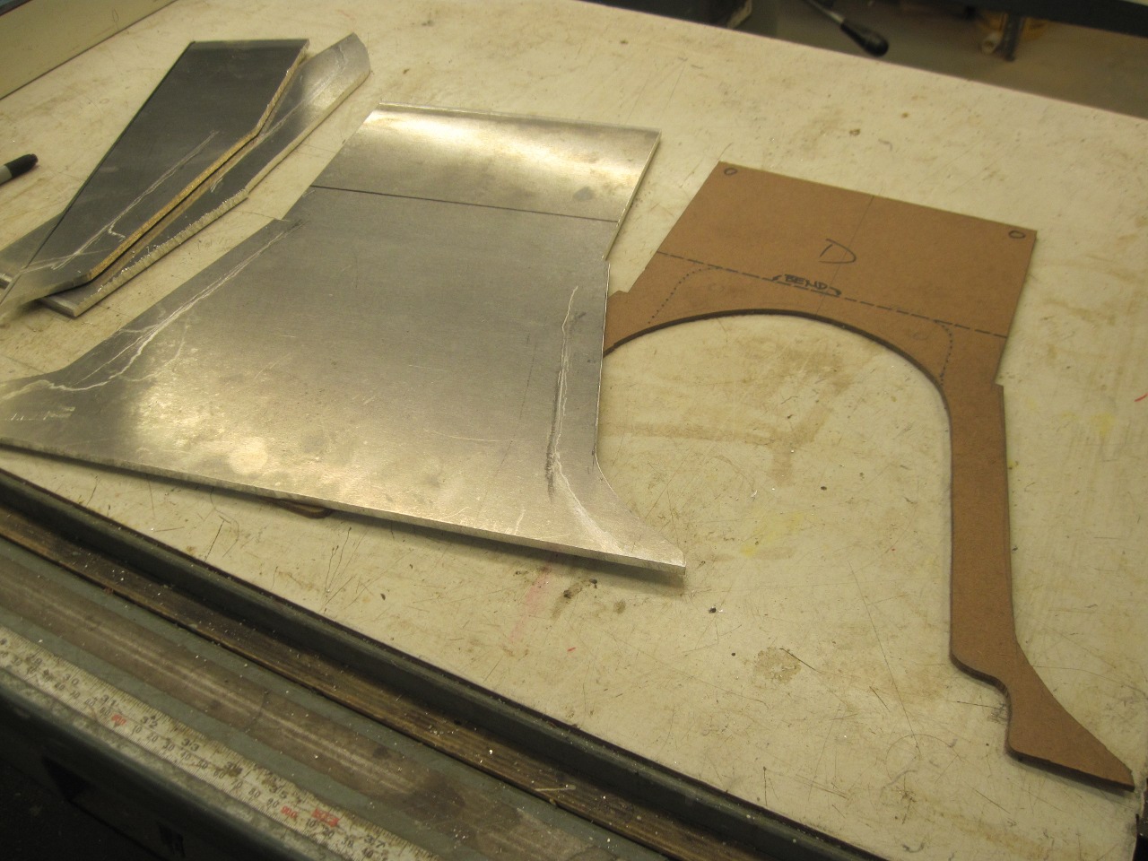
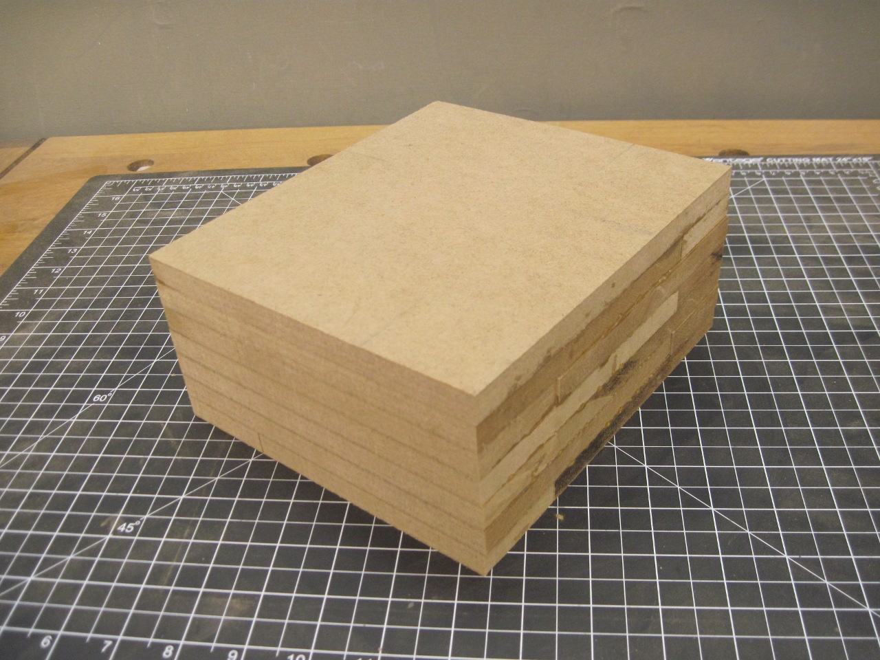
First
I made a pattern of the necessary shape. It was an iteritive
process, with each step getting closer to what I wanted.

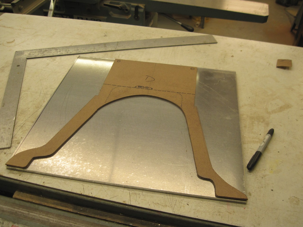
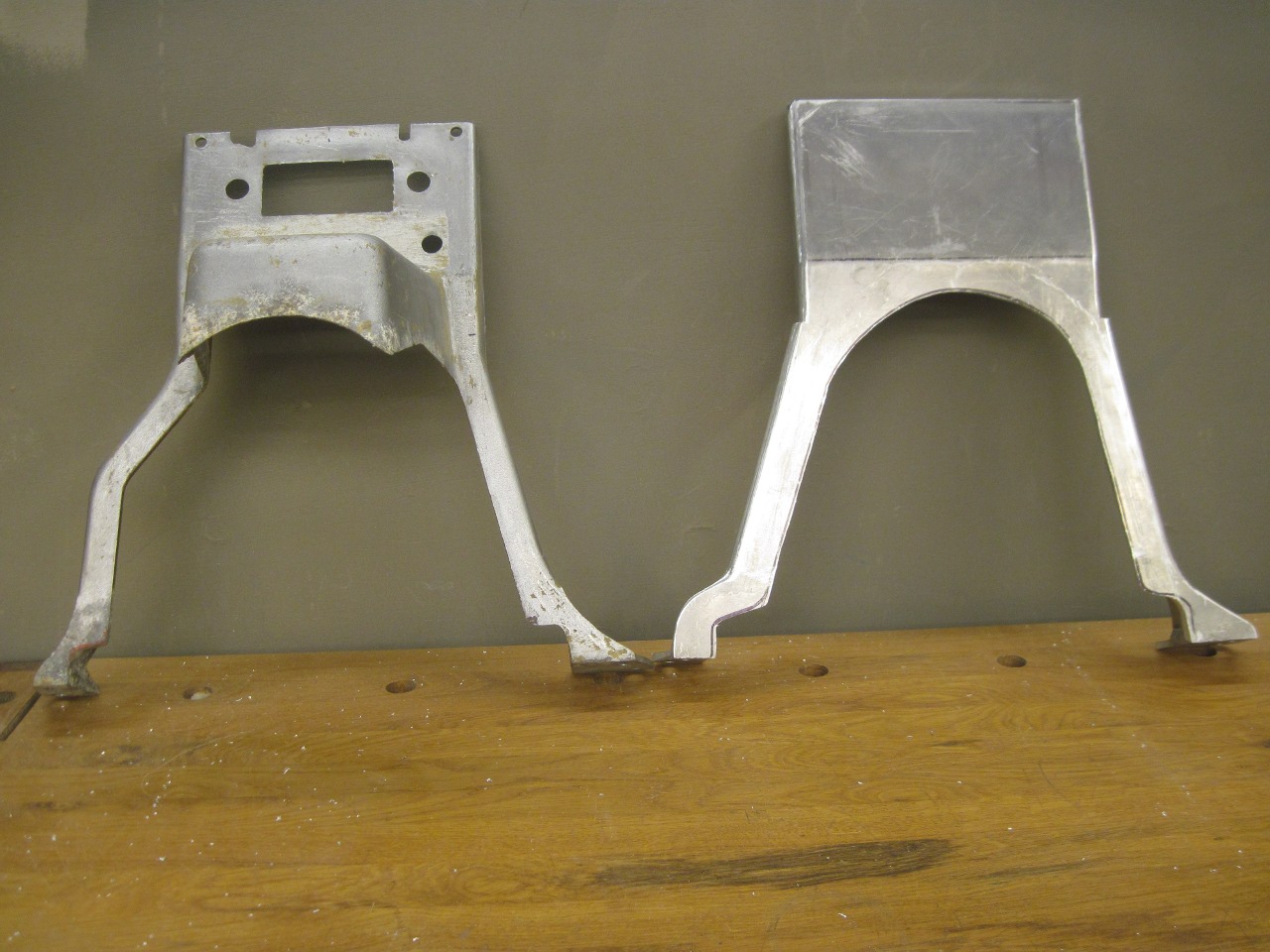
I
got a piece of 1/4" aluminum plate to cut the support out of. The
original piece is slightly thicker than that in places, but I think my
final part should be comparable to the stock one in strength. The
design I have in mind for a center console will include the area around
the shifter, so the new dash support won't need the nose on it that
surrounds the shifter. This of course simplifies the fabrication
immensely.
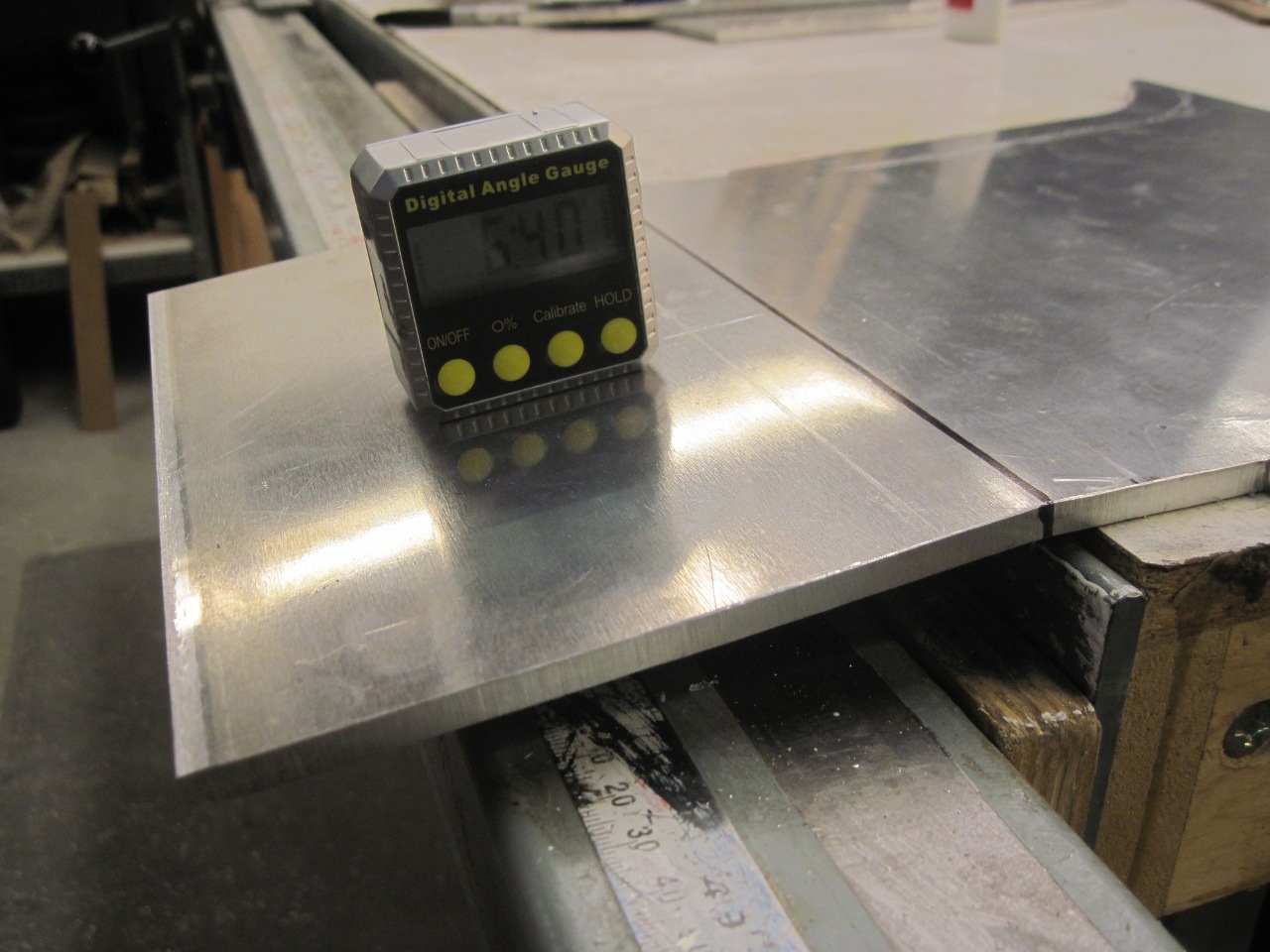
Even
then, the support is not as simple as it appears. First, there is
a slight bend just above the tunnel. It's a little hard to
measure accurately, but I came up with about 6.5 degrees. It was
a struggle to get that bend installed, but here it is.
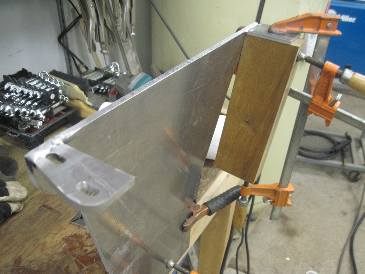
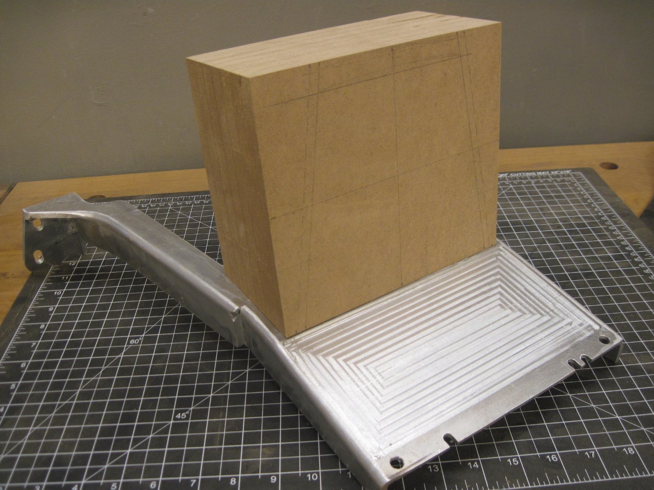
Then the side pieces and feet were cut and bent to resemble the original.

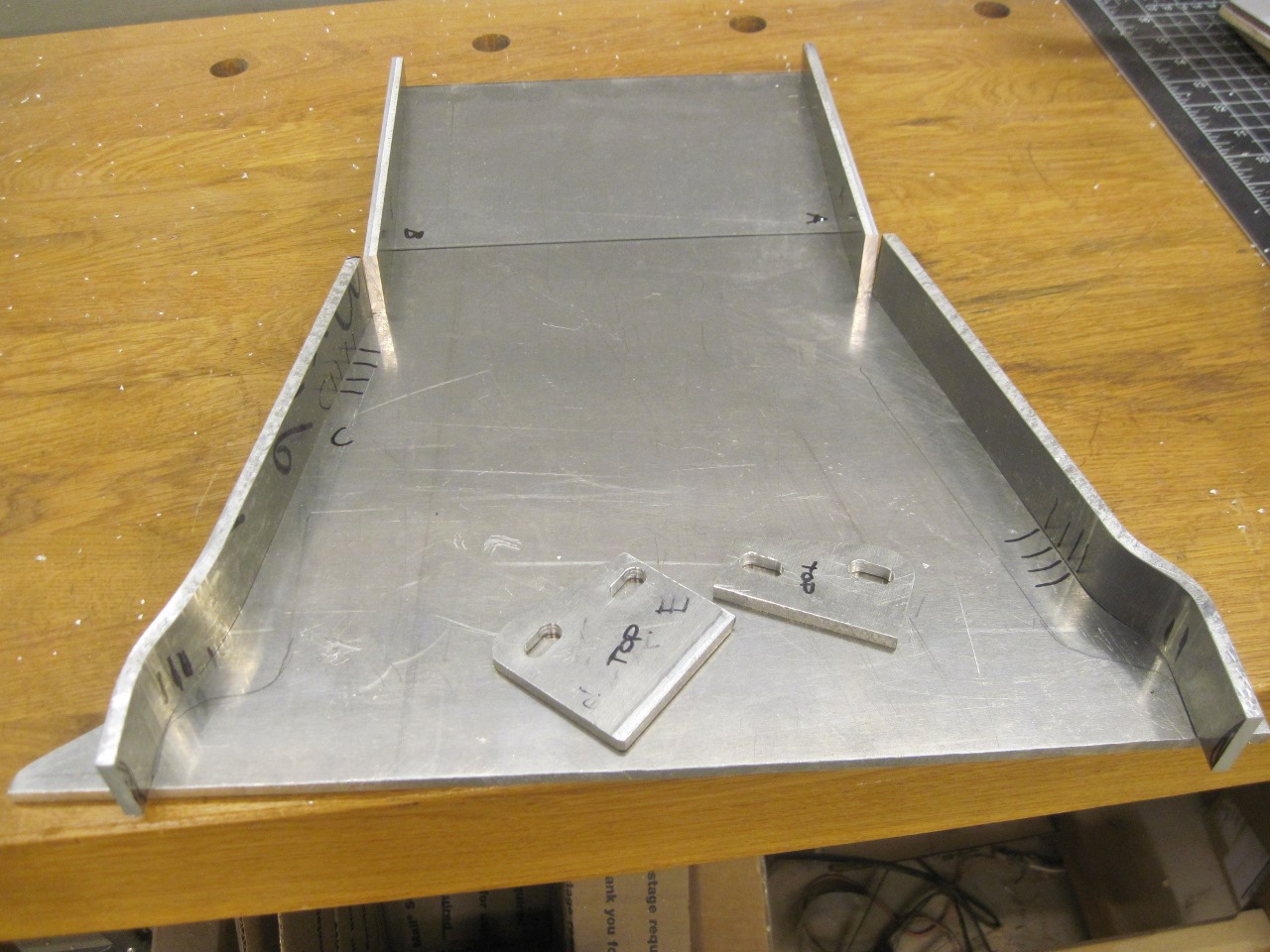
The feet are not at right angles to the legs. The angle is 95º and the block of wood is cut as a fixture.
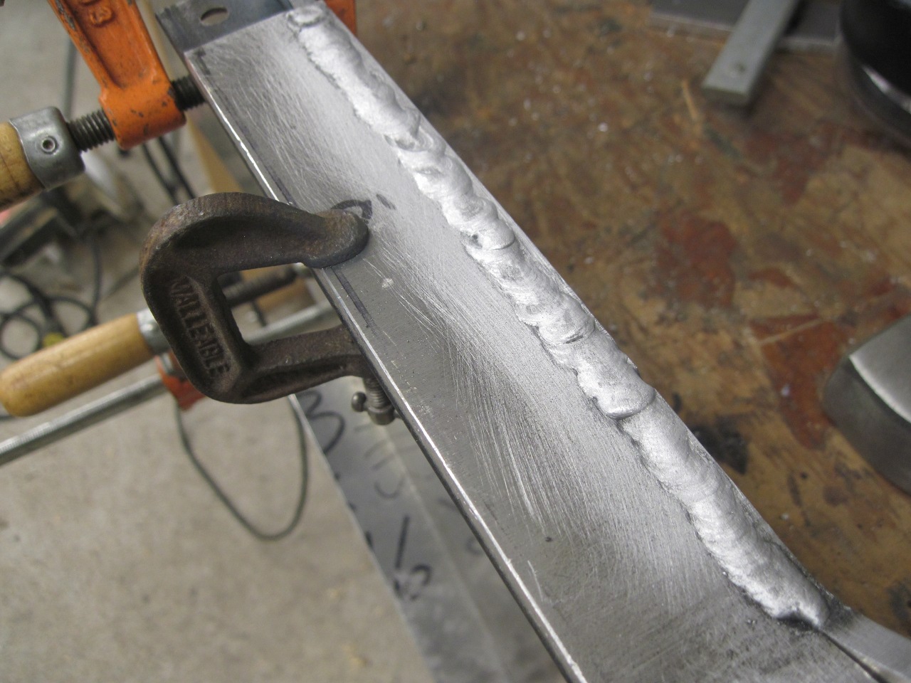
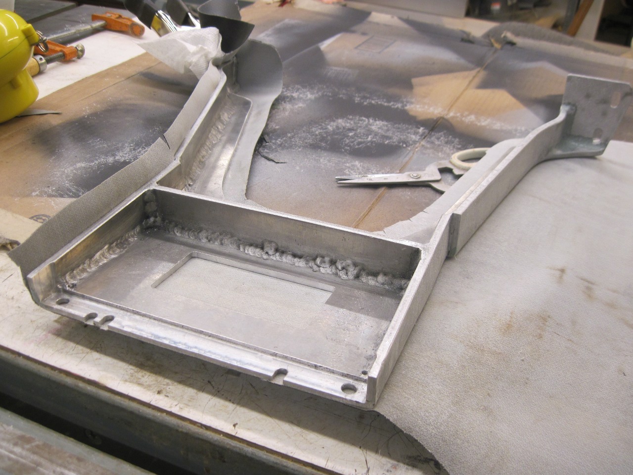
Now
while I'm just a self-taught MIG welder, I think I do pretty OK these
days with steel welding. This job, however, is my first attempt
at aluminum MIG. I bought a spool gun and a bottle of Argon, and
did a fair amount of practicing on scrap. Finally, I got tired of
the rehearsals, and decided to get down to it, right or wrong. I
ground a good sized chamfer on the outside corner joints, and dove in.
This is the best of my welds. Some of the others are, well,
not as good. I don't worry much about strength, but wish I could
make consistently good looking welds.

For good measure, I welded all of the inside corners.

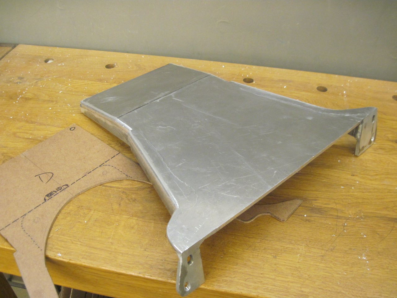
Then
routed a radius on the perimeter, and finally removed the interior
waste. In this view, the tunnel cutout of new support looks a
little asymmetrical. That's because the tunnel is a little
skewed. The buck for the tunnel was made from the old tunnel,
which was apparently a little distorted. Installed, this
shouldn't be visible. Also, final trimming of the fit hadn't been
done yet.
The test fit, and various mounting holes and slots.
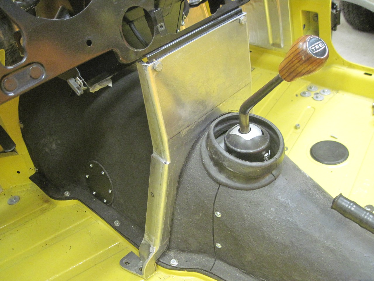
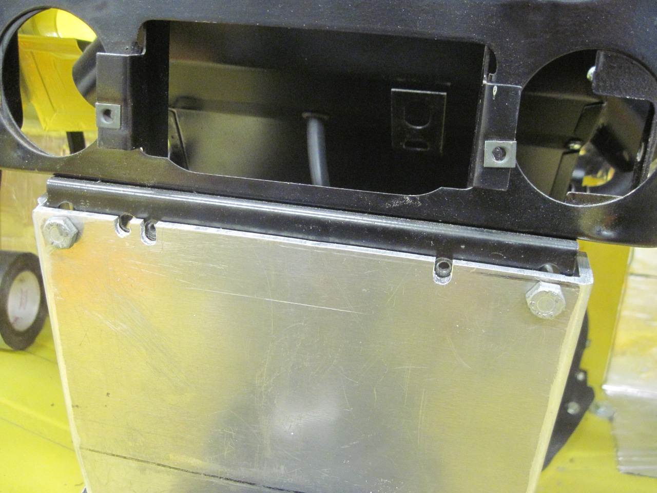
This
is where it will stand while I work out what devices will get mounted
on the support. I don't think I'm going to install a radio, at
least not a conventional one. I think the panel will get
seat heater switches, radiator fan override and indicator, a cabin
light switch, and I'm not sure what else. And then there is the
shifter. Still thinking on that one.
Update--July 2, 2017
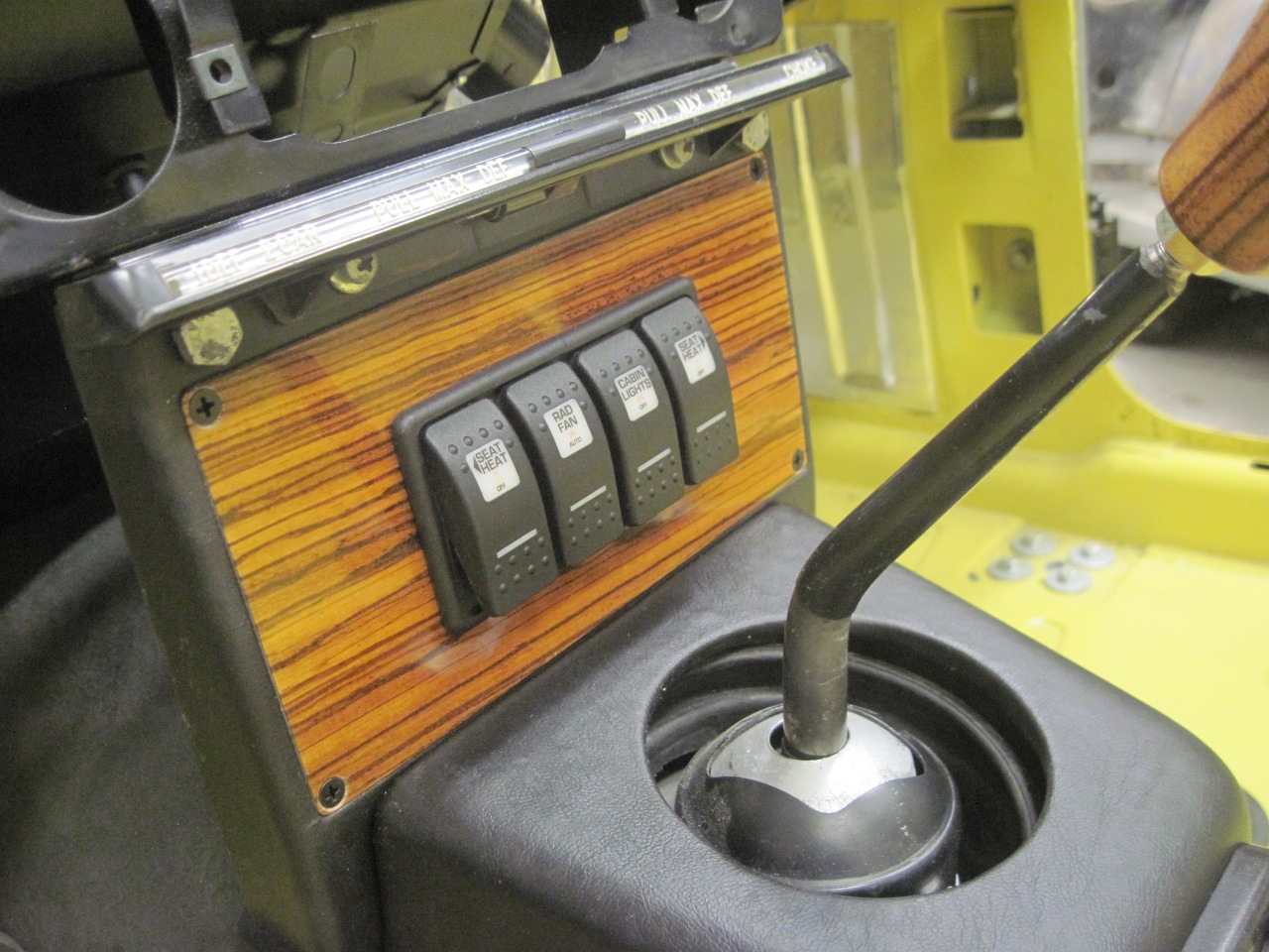
Switches and power outlets
After
a lot of thought, I finally decided how to use that wonderful new blank
space on the new support. There would be four switches:
right and left seat heaters, the radiator fan override switch, and the
cabin light switch, which was found on the original support. I
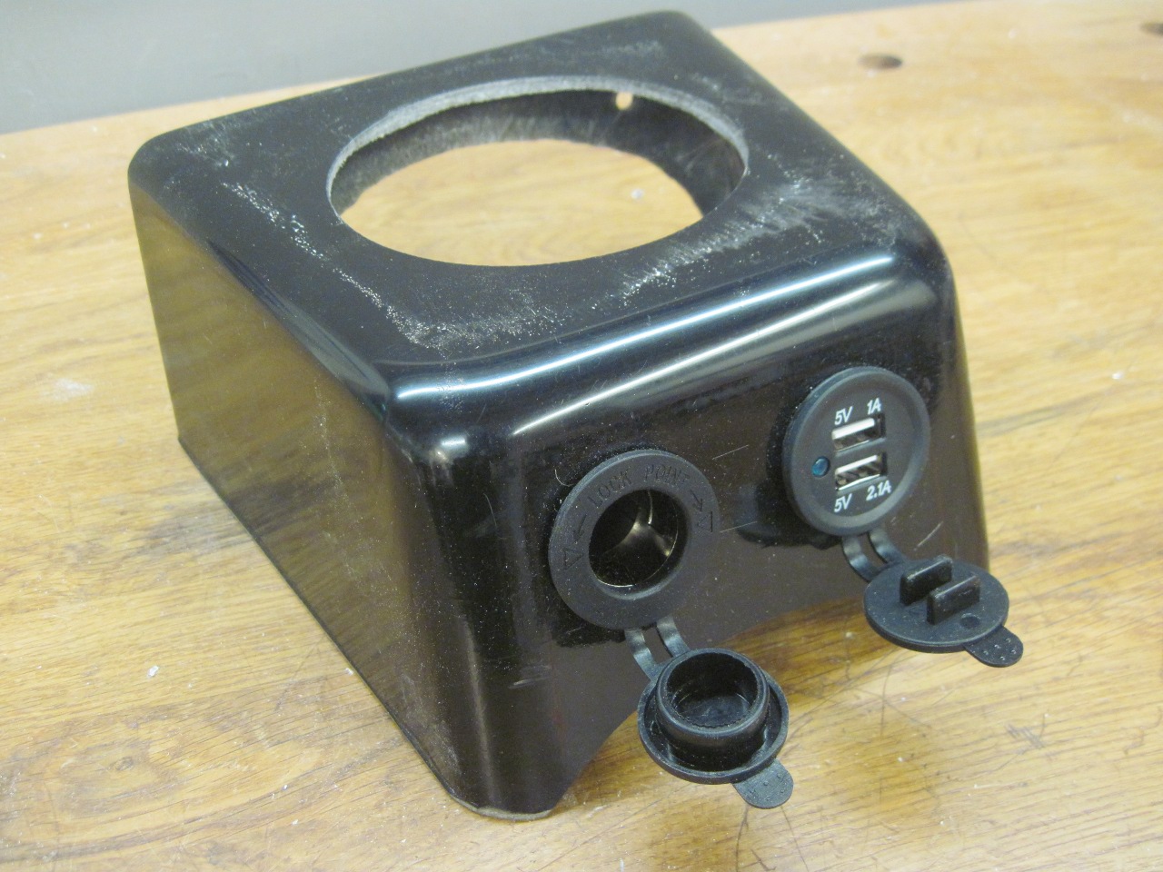
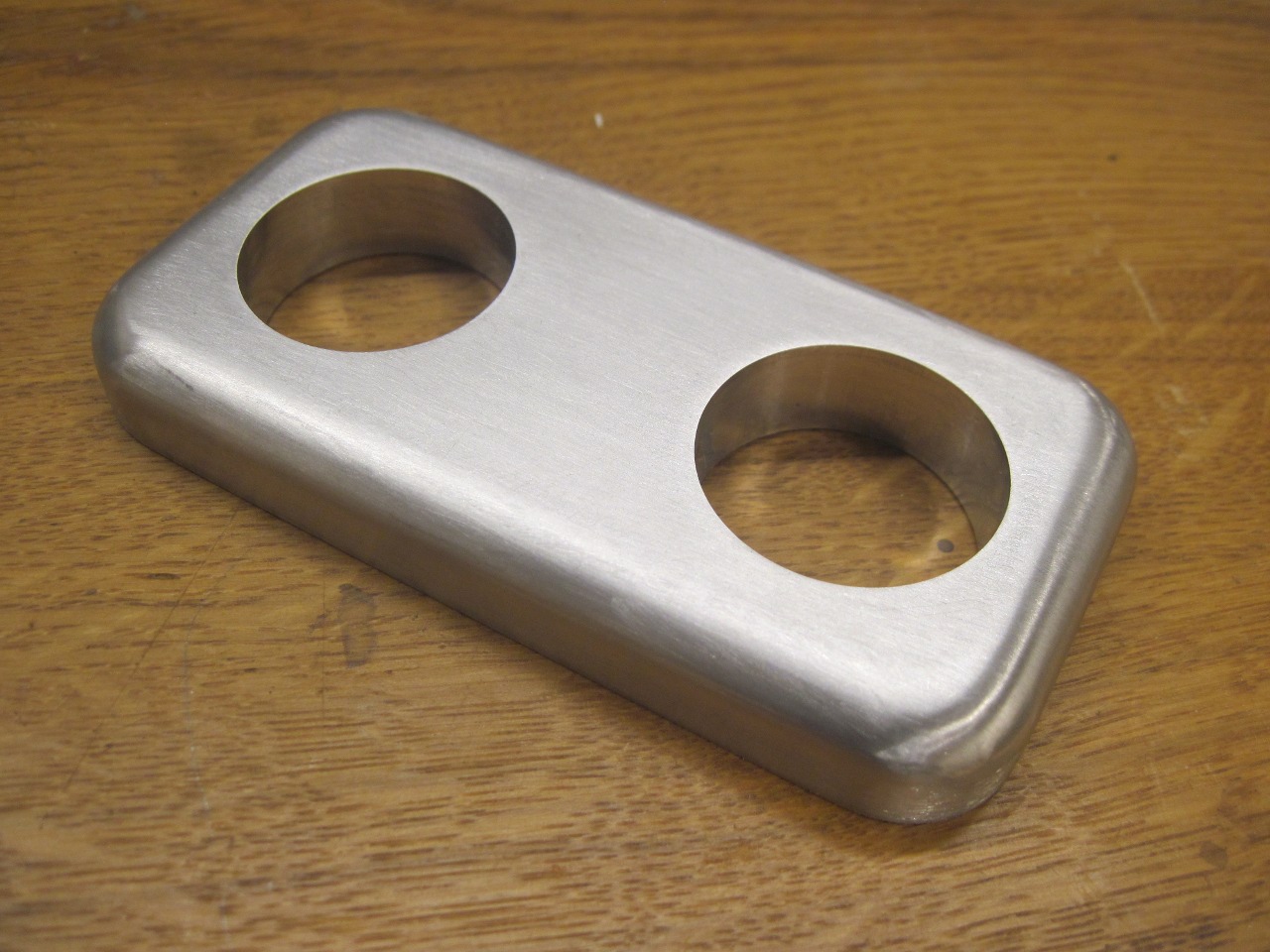
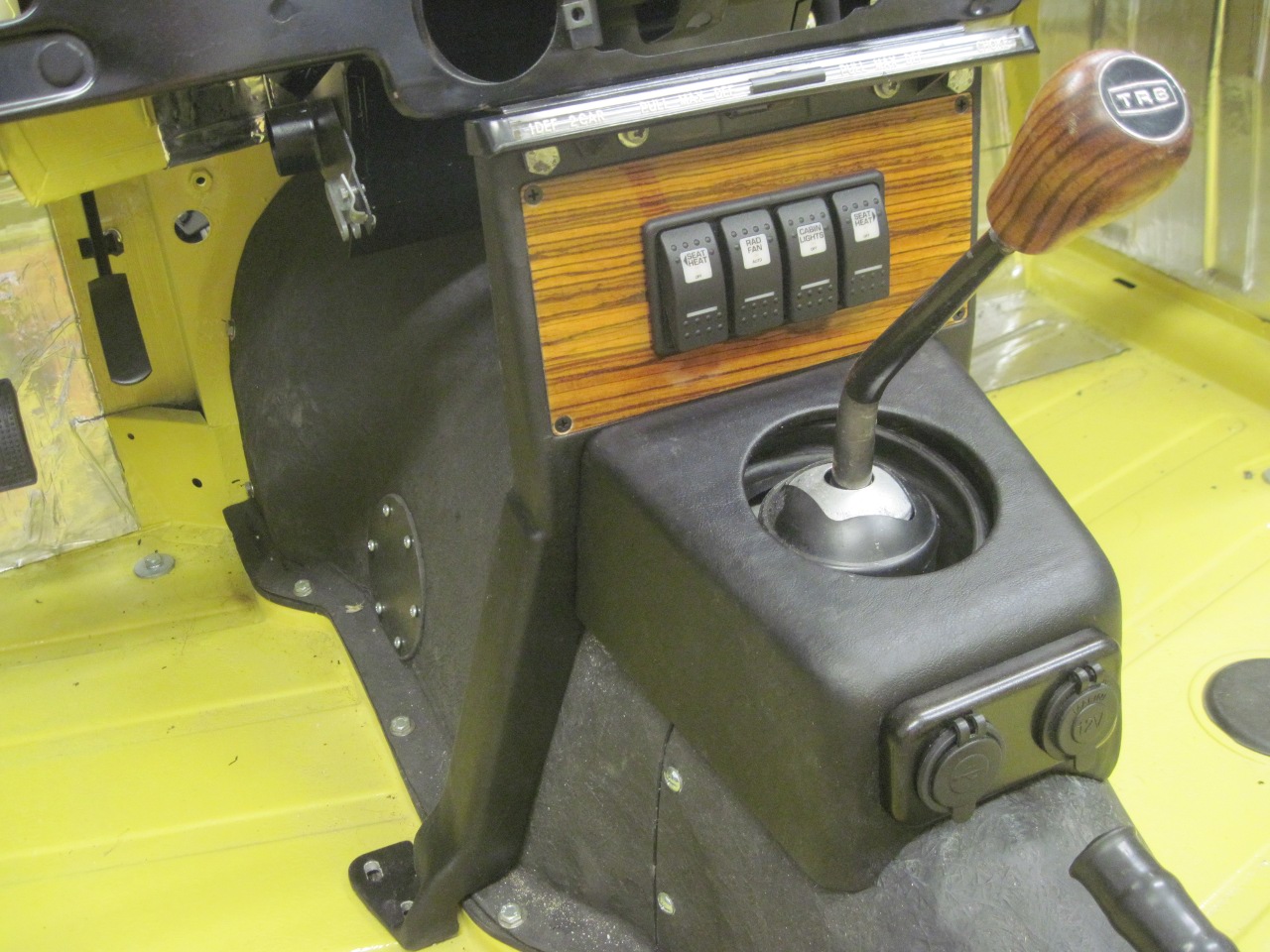
also wanted two power outlets--one 12 V cigarette lighter type, and a
dual USB port, but I thought these made the panel a little too crowded,
so I moved them down to the shifter surround.
I
did quite a search for switches. I wanted them to all be the same
style, but of course the electrical function would be different among
them. The toughest criteria was for the seat heater switches.
I wanted a dual level Off/Lo/Hi function, which would require a
three position "double throw" switch. Though double throw
switches are extremely common, I really wanted an Off-On-On
configuration instead of the standard On-Off-On arrangement.
I
landed on a switch line from Carlingswitch that are very popular in the
custom boat and RV world. These switches also each have two
indicator lenses with internal LEDs. The switches for the seat
heaters aren't exactly what I was looking for, but close enough that I
can make them work.

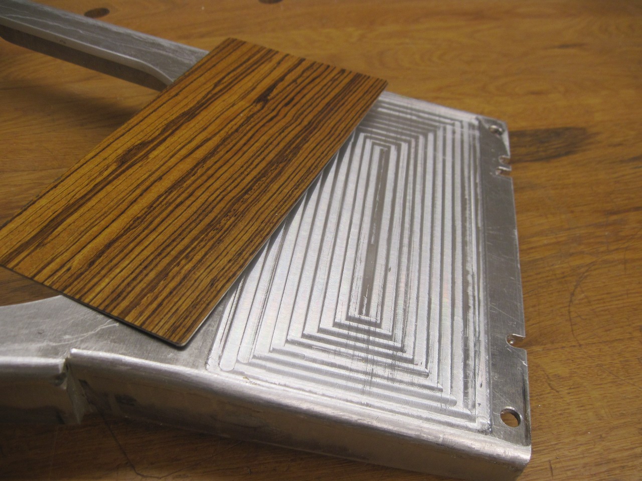
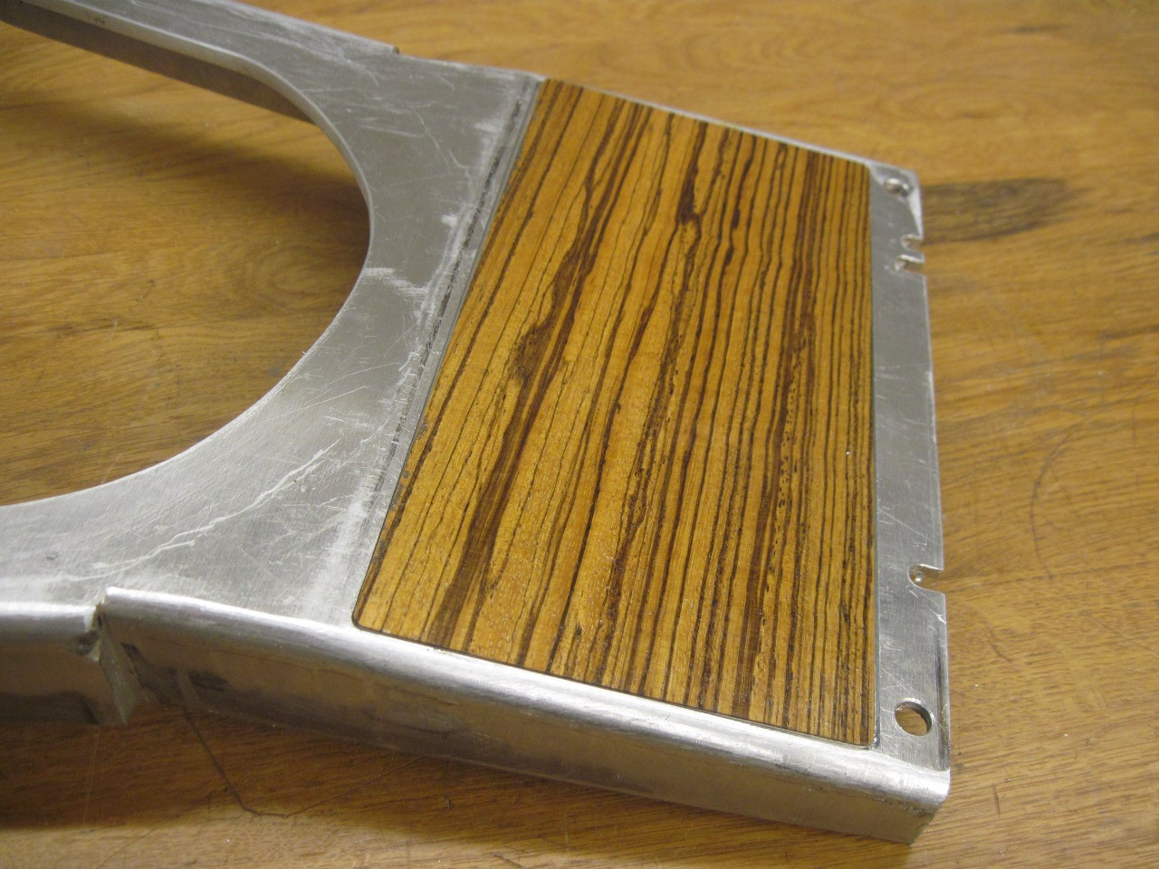
I
decided to include a zebrawood panel on the support to match the
dashboard. To keep the thickness down, I laminated the zebrawood
veneer to a sheet of aluminum with epoxy, then cut a shallow recess in
the flat part of the support to receive the panel. The wood panel was finished to match the dash.
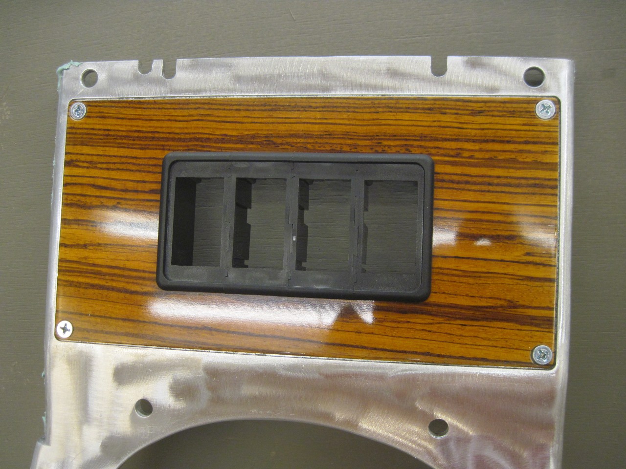
Then cut openings in both the panel and the support for the four-place switch bezel.


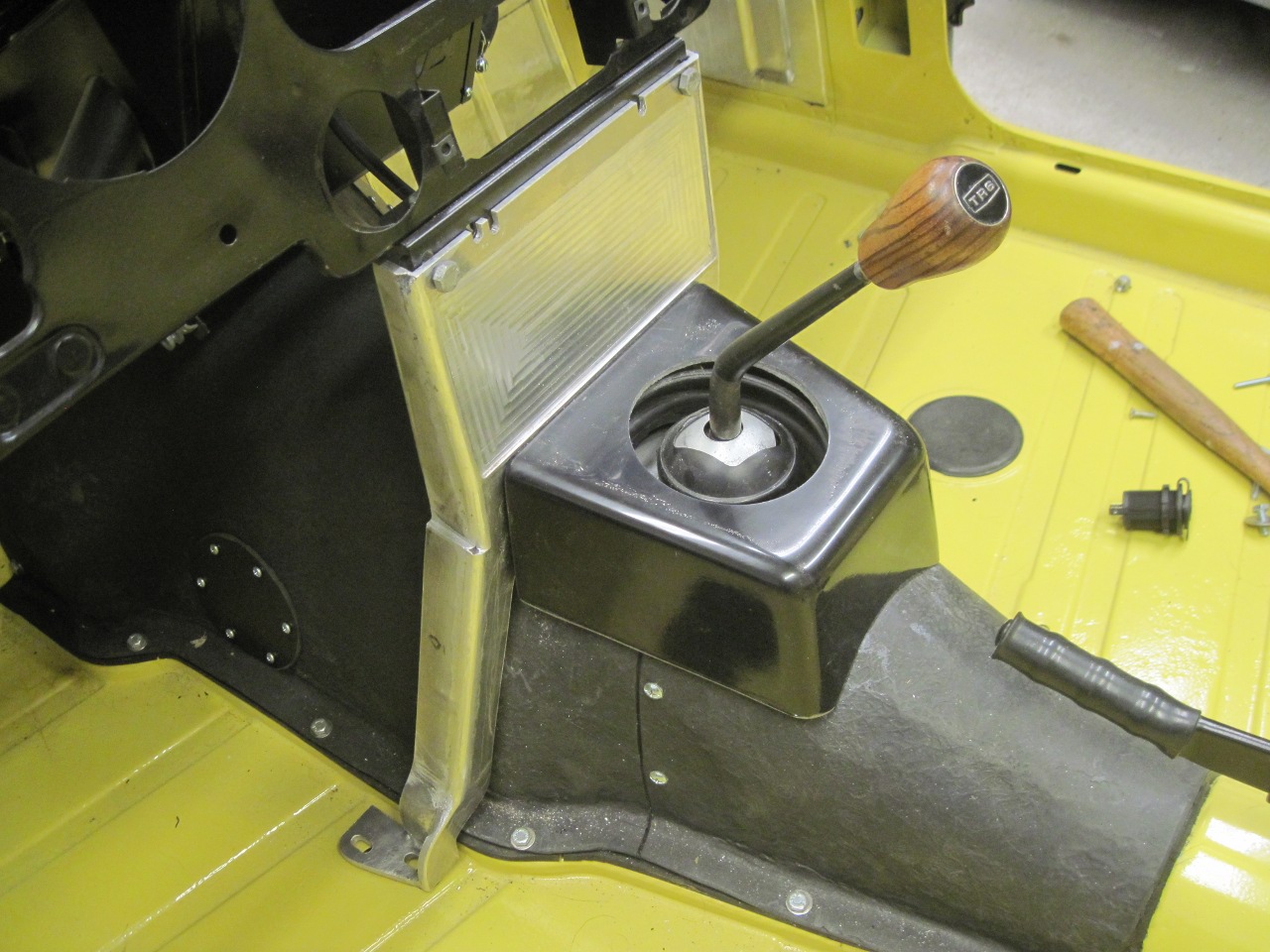
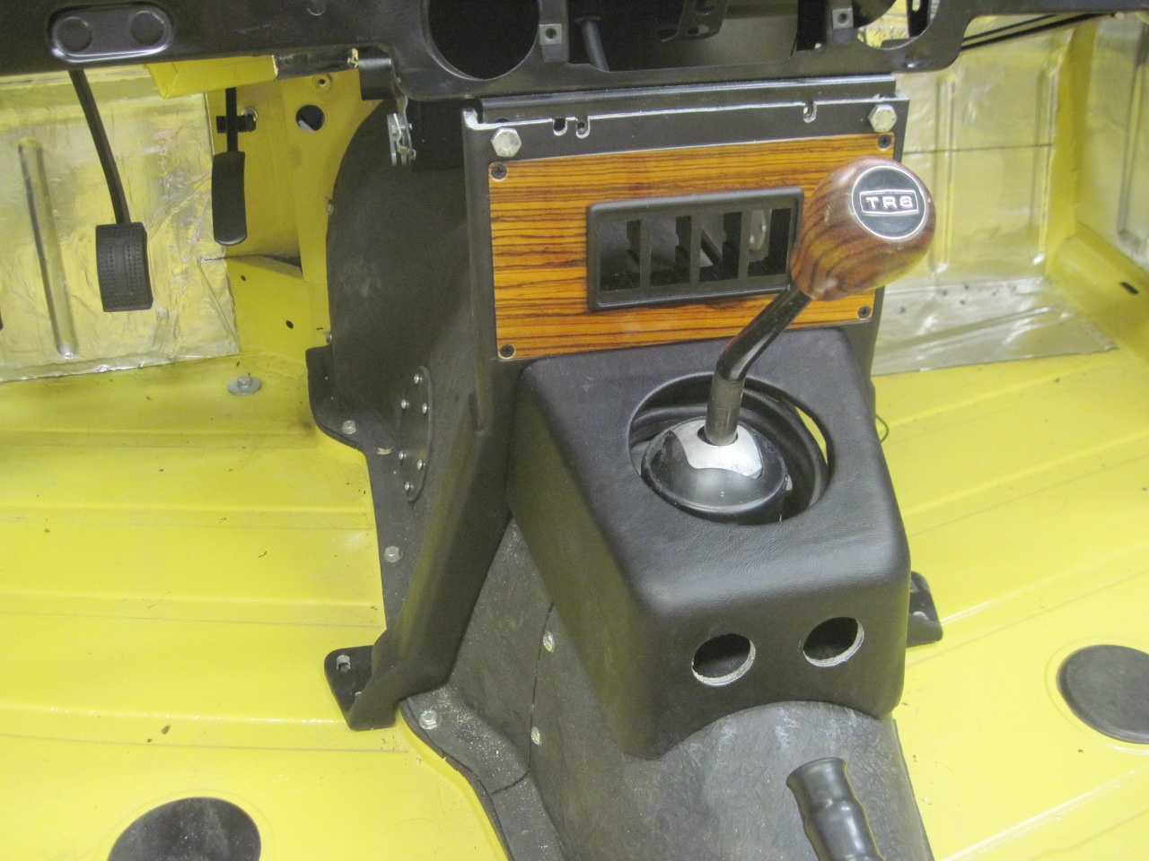
In
pondering what to do about the shifter surround, I finally decided to
more or less duplicate the look of the stock part. I
really want the car to look and feel like a TR6, and I think this
part of the car is almost iconic. I settled on making a
fiberglass part that would fasten to the support. Though it looks
just like the original, it is actually slightly longer and wider to
accommodate the power outlets that will be in its aft end.
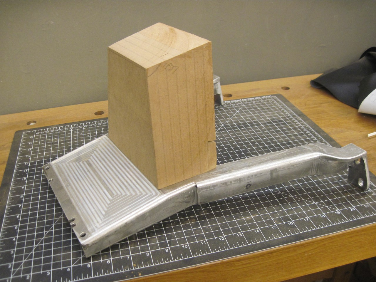
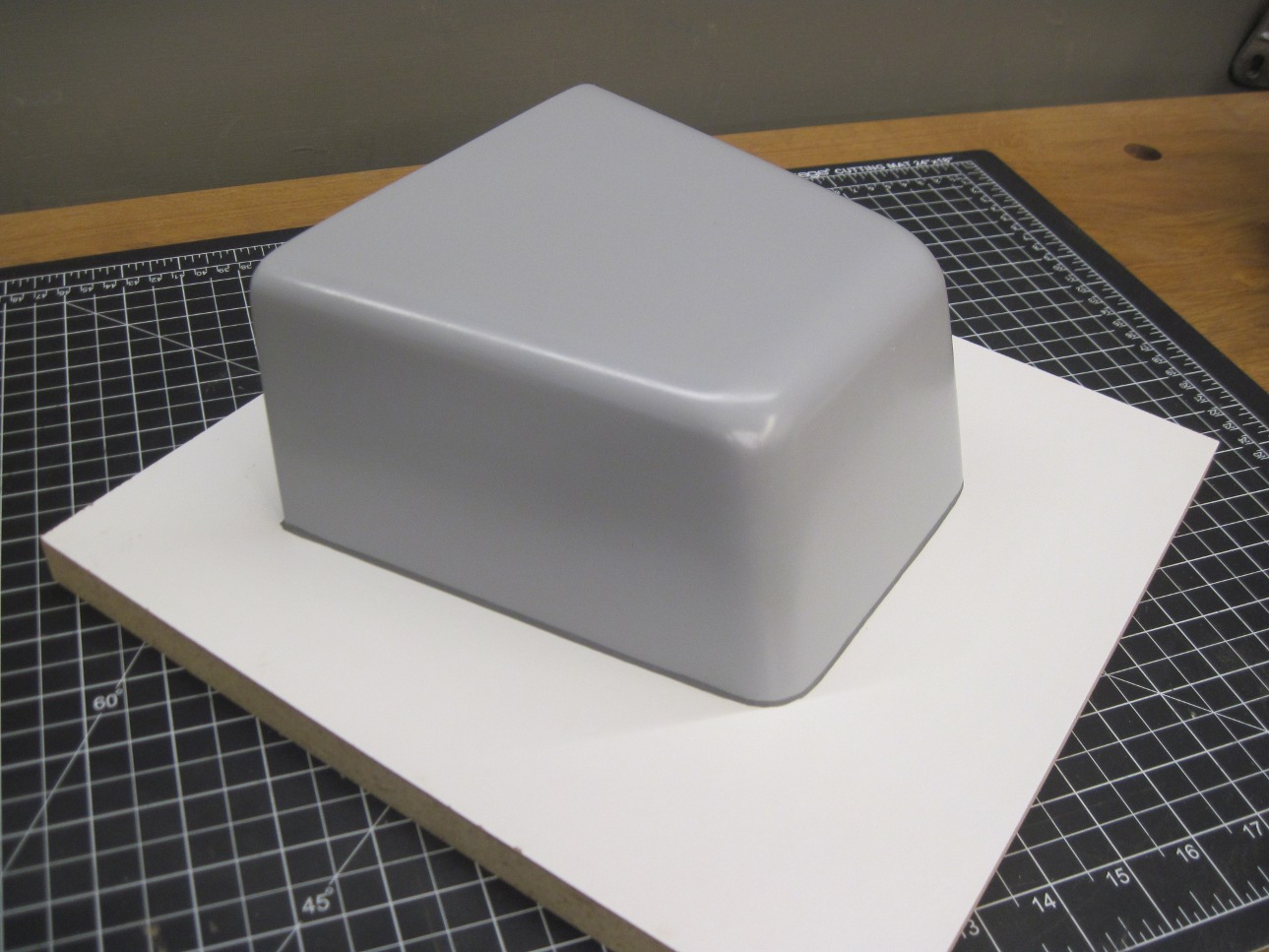
I
started with a block of glued up MDF and gradually shaped it to look
like the original. This was tricky since there no right angles,
and no two surfaces are parallel.
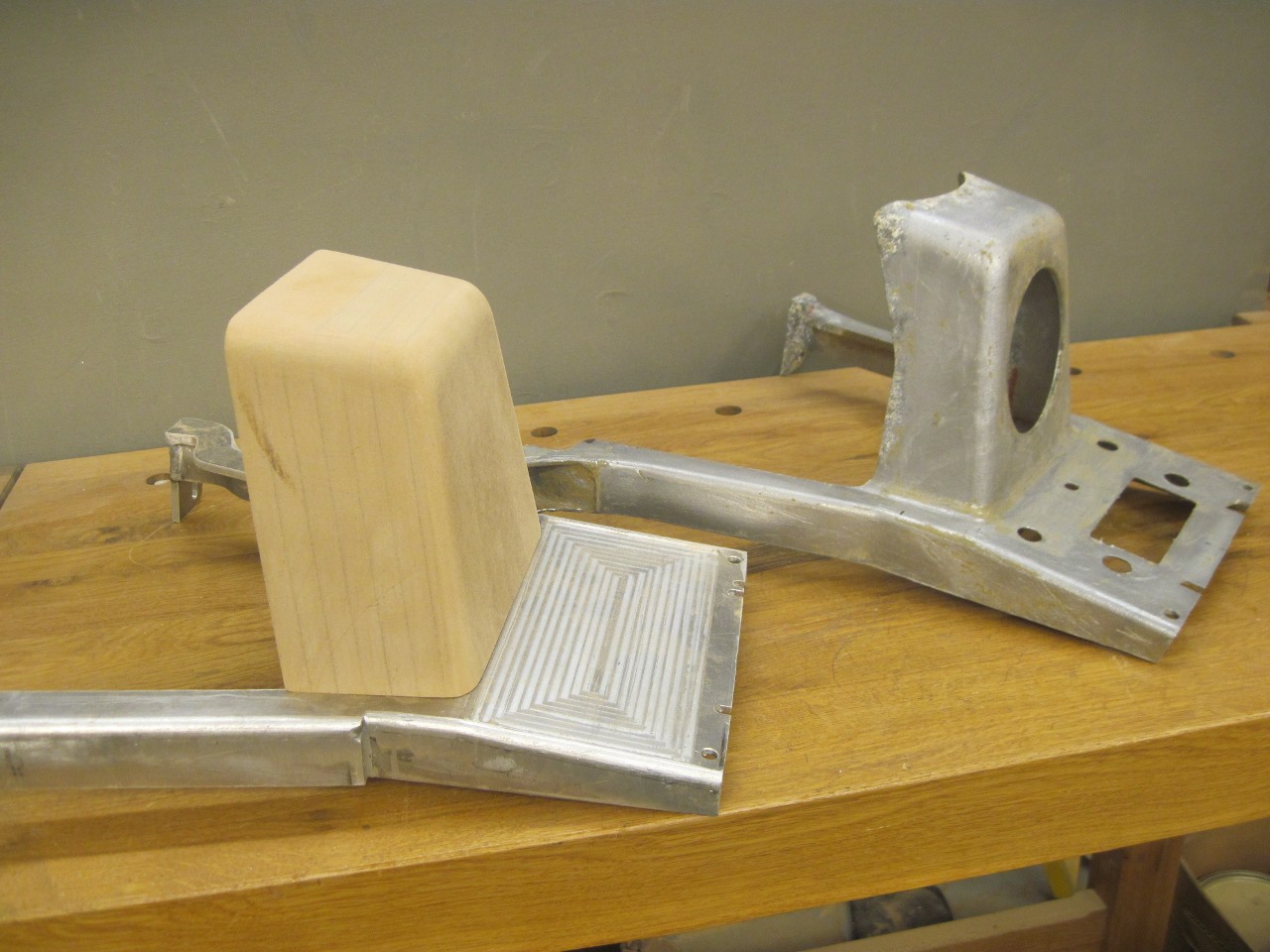
The block became a pattern to make a fiberglass mold.
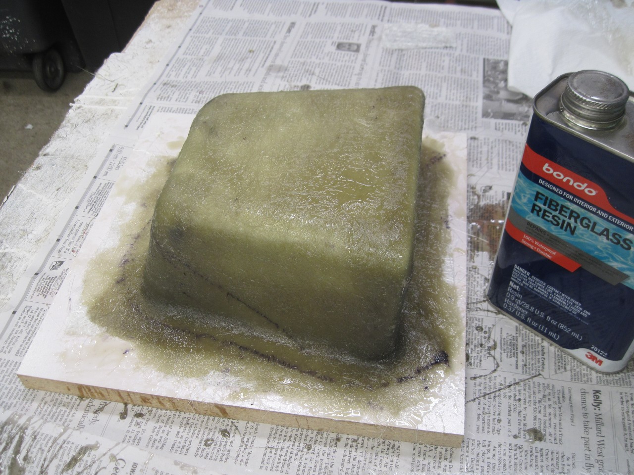
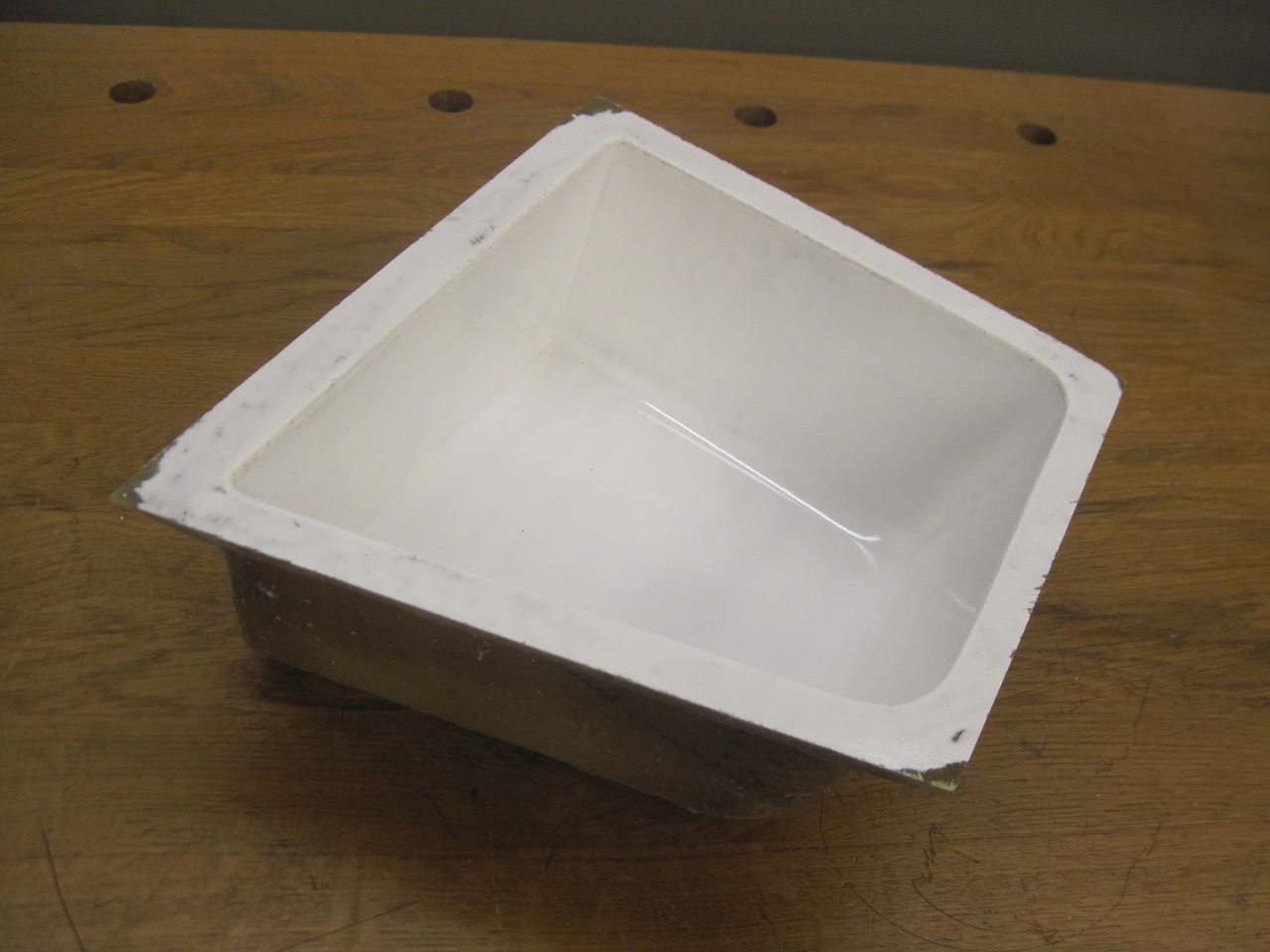
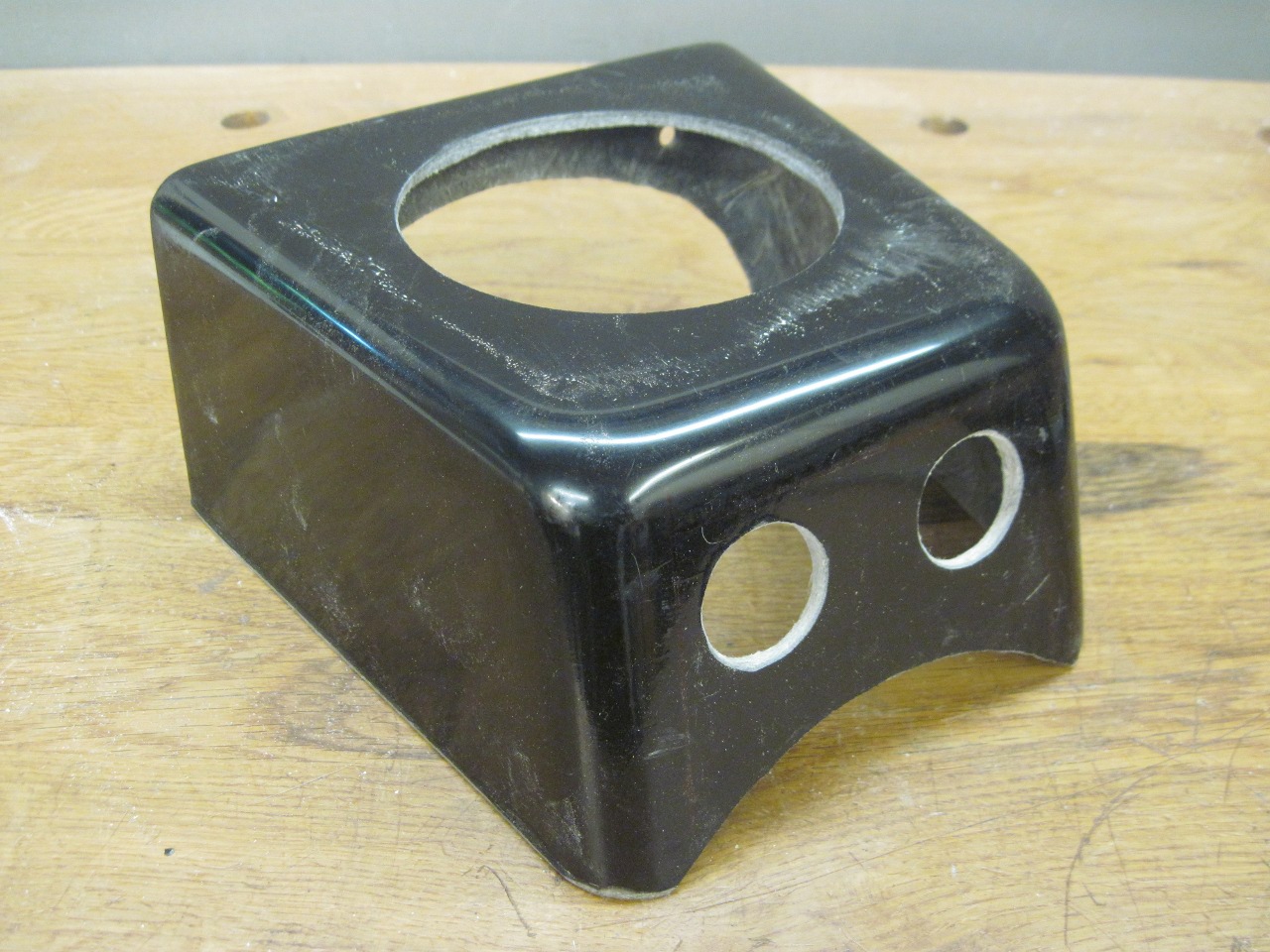
The
mold in turn made a part just like the pattern, but hollow. After
trimming and cutting some coutours, the fit was pretty good.
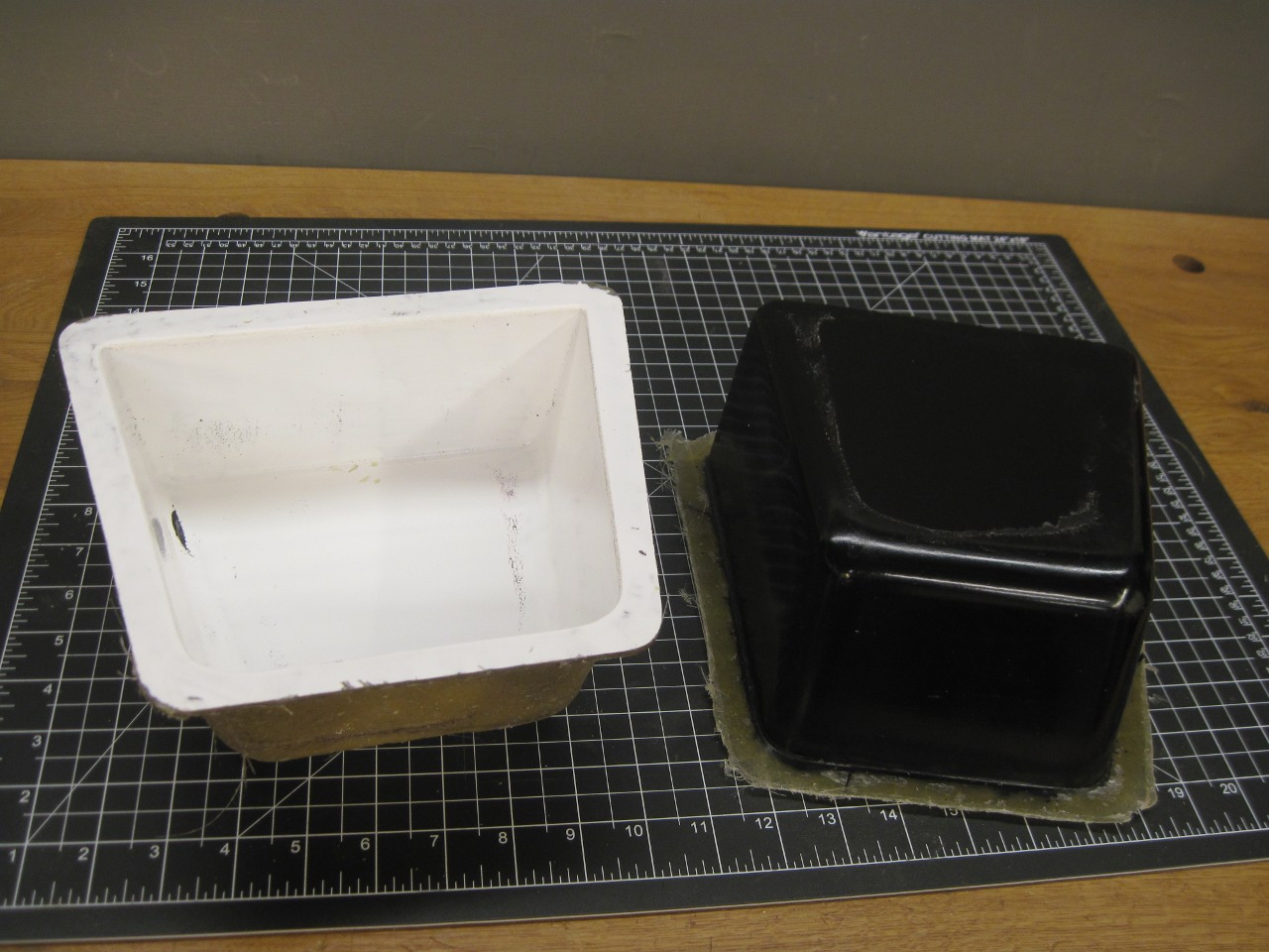
The power olutlets are going here.
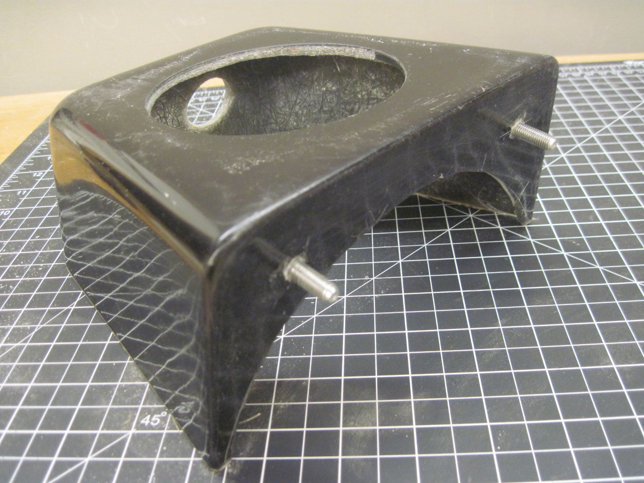
I fiberglassed in a couple of studs on the backside to fasten it to the support.
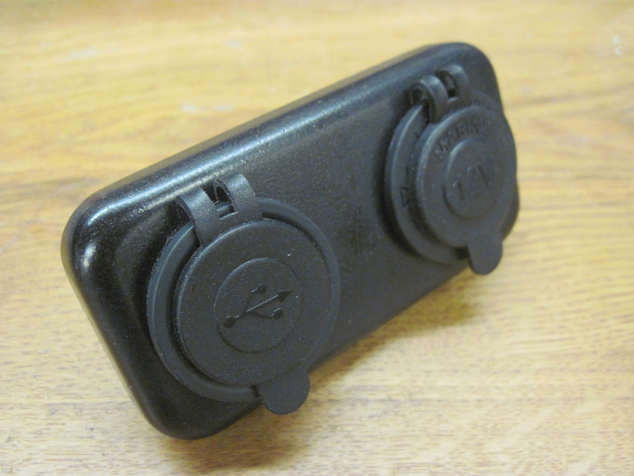
With
everything cut, trimmed, and test fitted, it was time to cover the
parts with vinyl as original. The support was pretty easy, with
the only challenge being around the feet.
The
shifter surround on the other hand was a real stretch (pun intended).
I pulled the vinyl right over the holes and cut them out later.
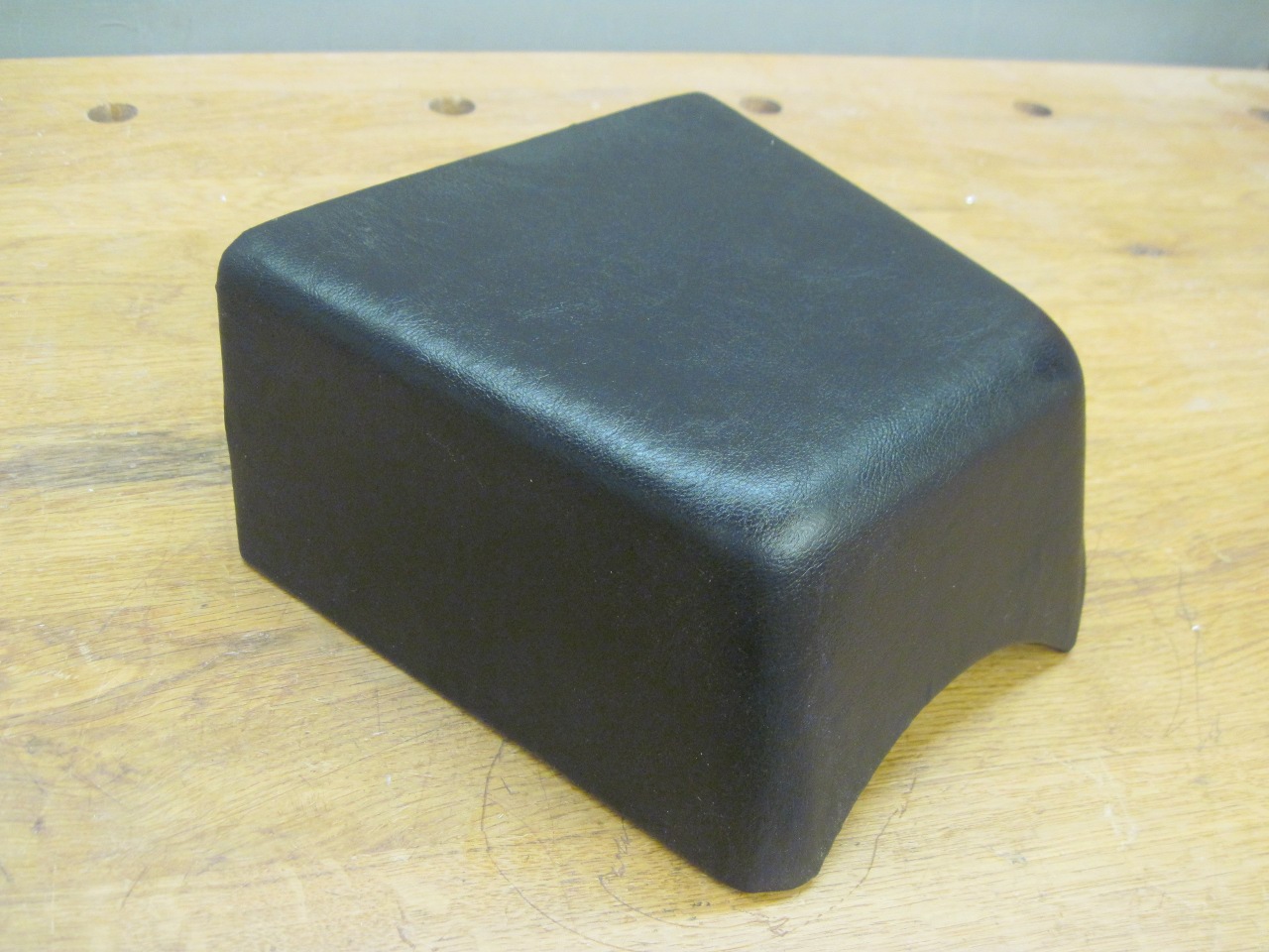
The vinyl really makes it look more finished.
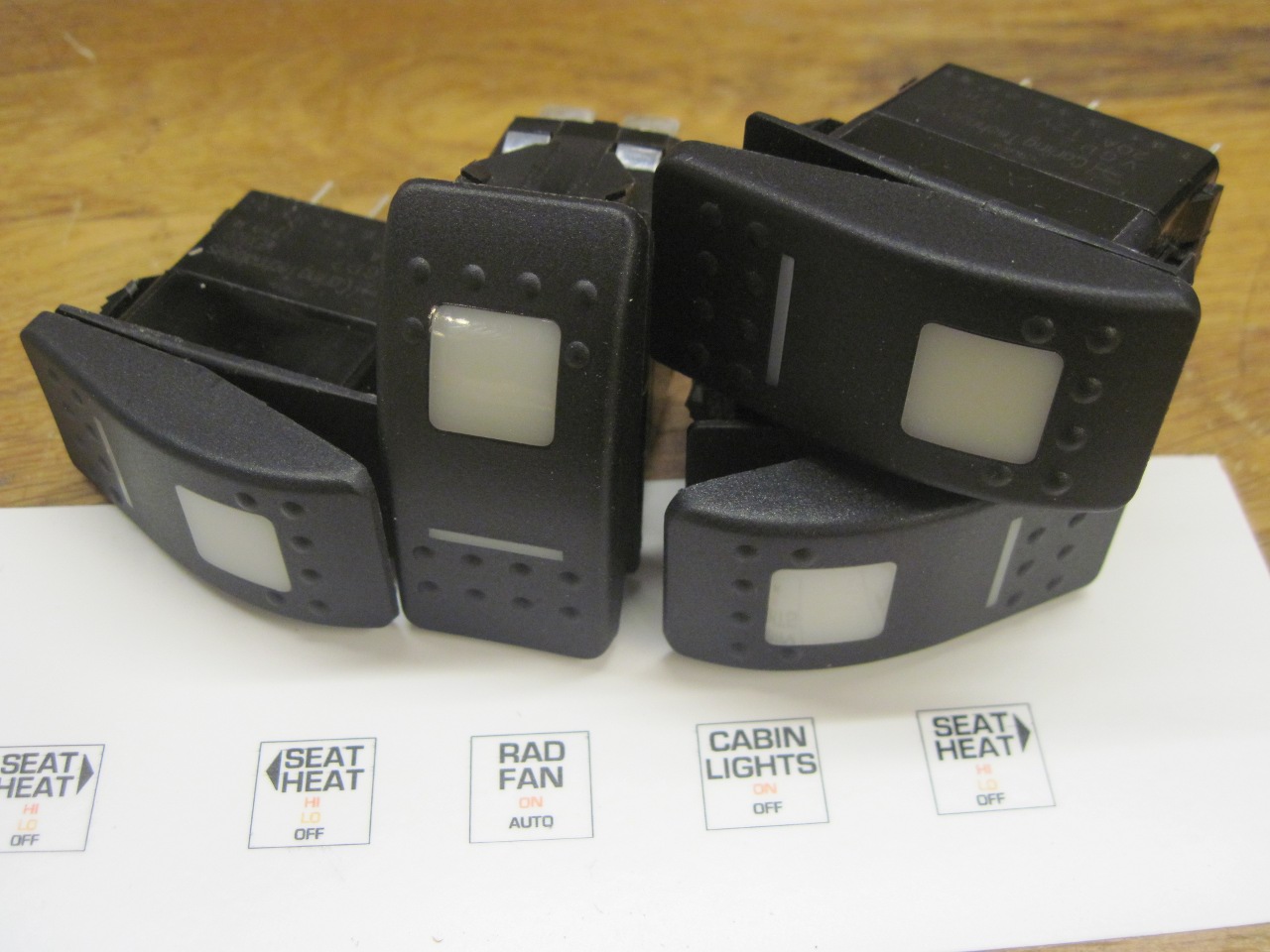
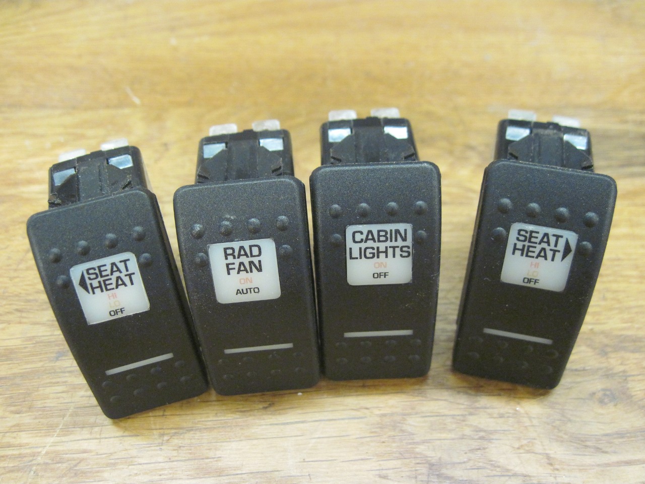
And
now a nice little detail on the switches. Each switch has an
illuminated lens big enough for a legend. I could buy the
switches with some common legends, mostly marine oriented, but I found
no seat heater legends. Even if I had found them, they would have
been the little pictographs common on products today that are
sold internationally.
I
ended up designing my own legends and printing them on water slide
decal paper. I started with the pictogtraph style, but later
decided to just use English.

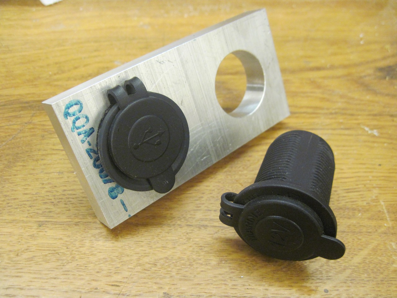
On
what I thought was the final fitup, I found that the power outlets,
being pretty long, were fouling the rubber shift boot on the gearbox
cover. This is why I made the surround a little longer, but
apparently not enough. I fixed the problem by making this little
spacer to move the outlets rearward a little.
I guess I'm pretty happy with the look of the new switches. I really want to see how it looks with the wood dash.
Comments to Ed at elhollin1@yahoo.com
To my other TR6 Pages