To my other TR6 pages
February 5, 2017
Seat Belts
My
car was fitted with 3-point inertial seat belts. This must have
been sort of a big deal back in the day, since I have seen some
early 70s ads bragging about it.
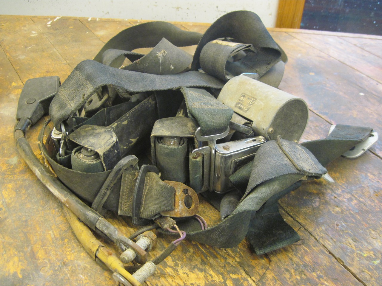
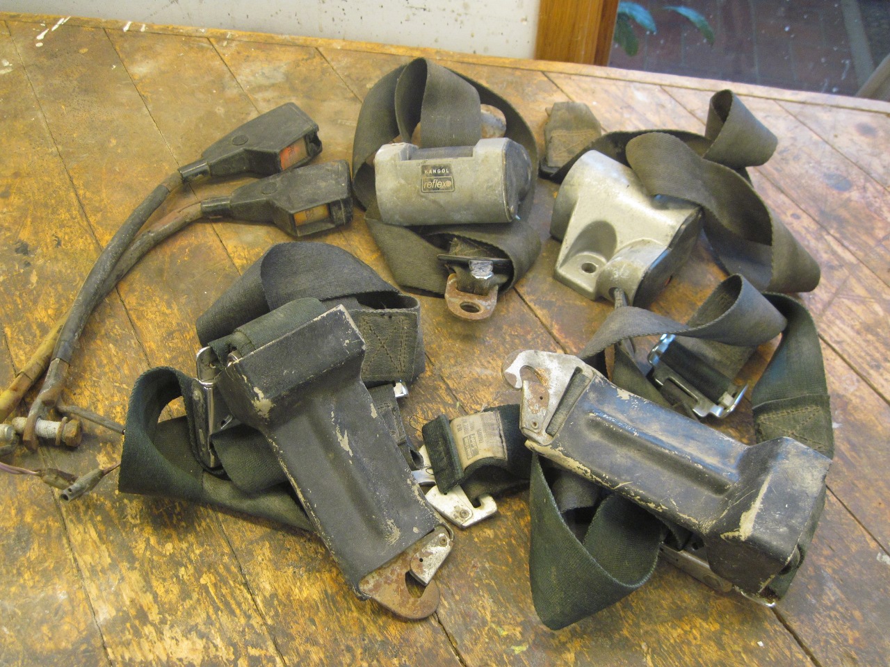
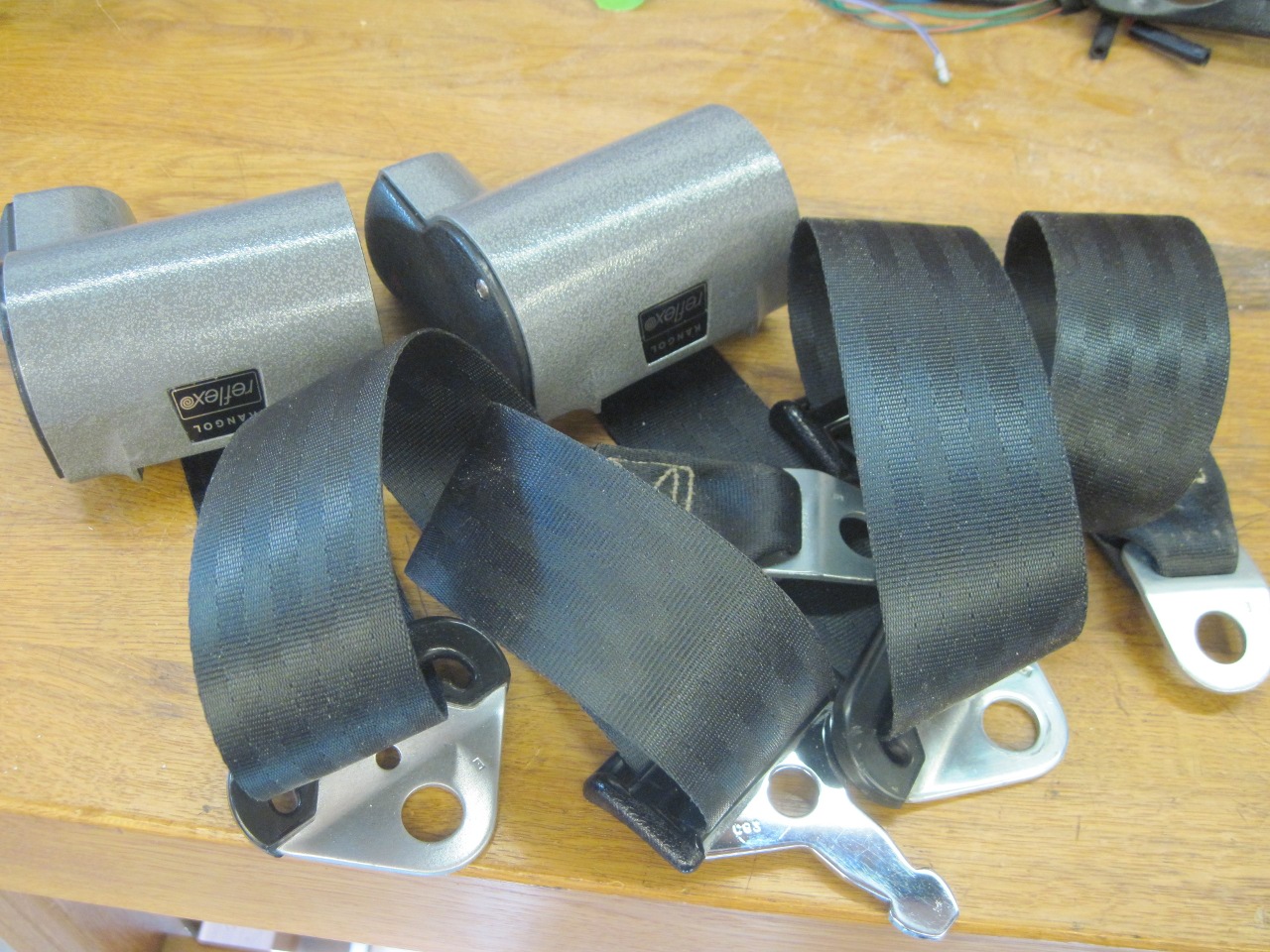
I
was a little overwhelmed at first when I dumped out the box with the
seat belts, until I realized there was a set of GT6 belts in there, too.
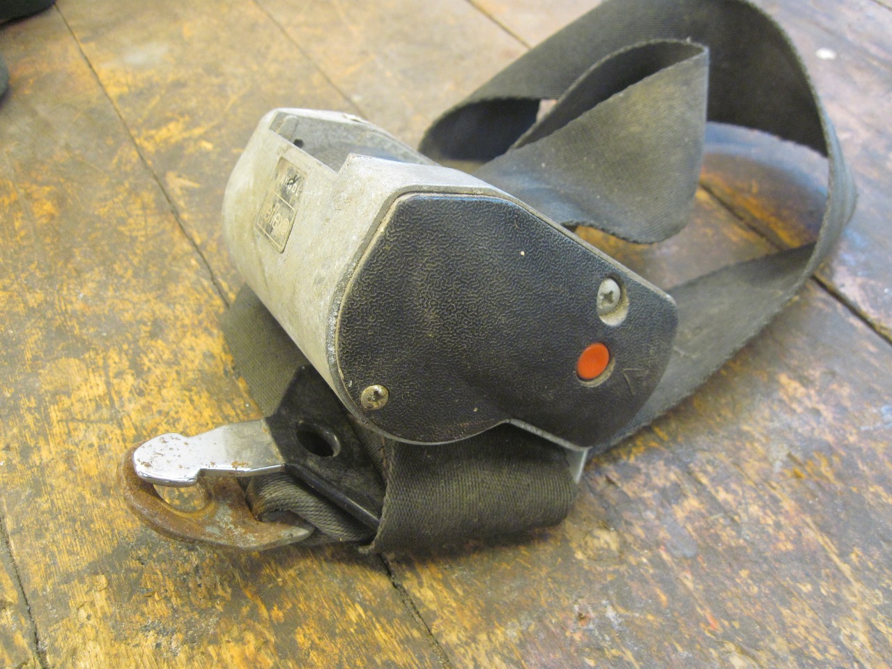
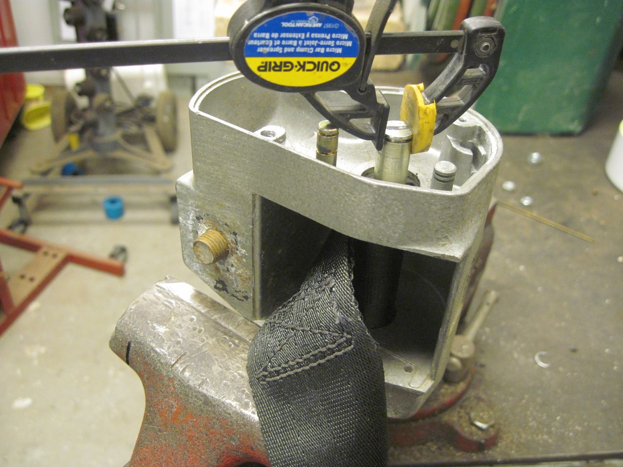
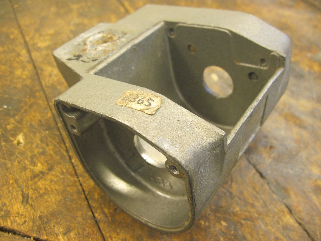
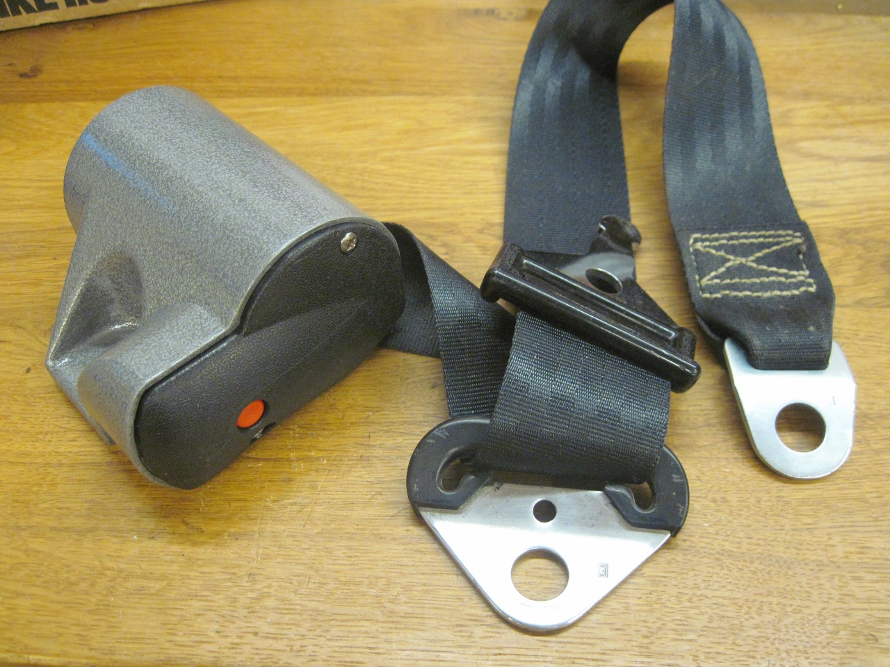
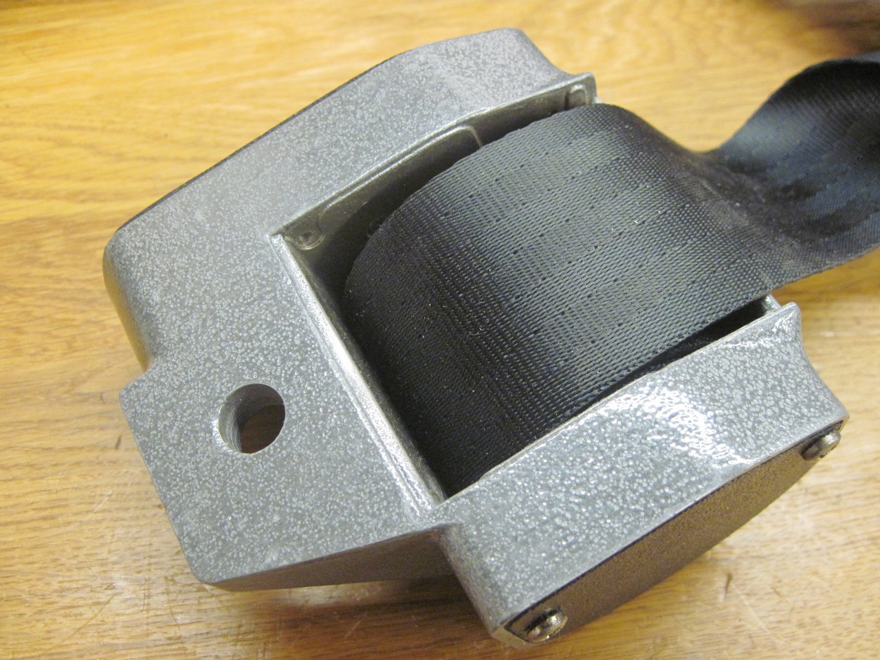
The
heart of an inertial system is a spring loaded reel which pays out the
belt freely except when there is a sudden motion of the car, in which
case it locks the reel. The reel, spring, latch, and acceleration
sensor are all in these aluminum housings mounted at the base of
the rear wheel wells. My units were dirty, crusty, and frozen.

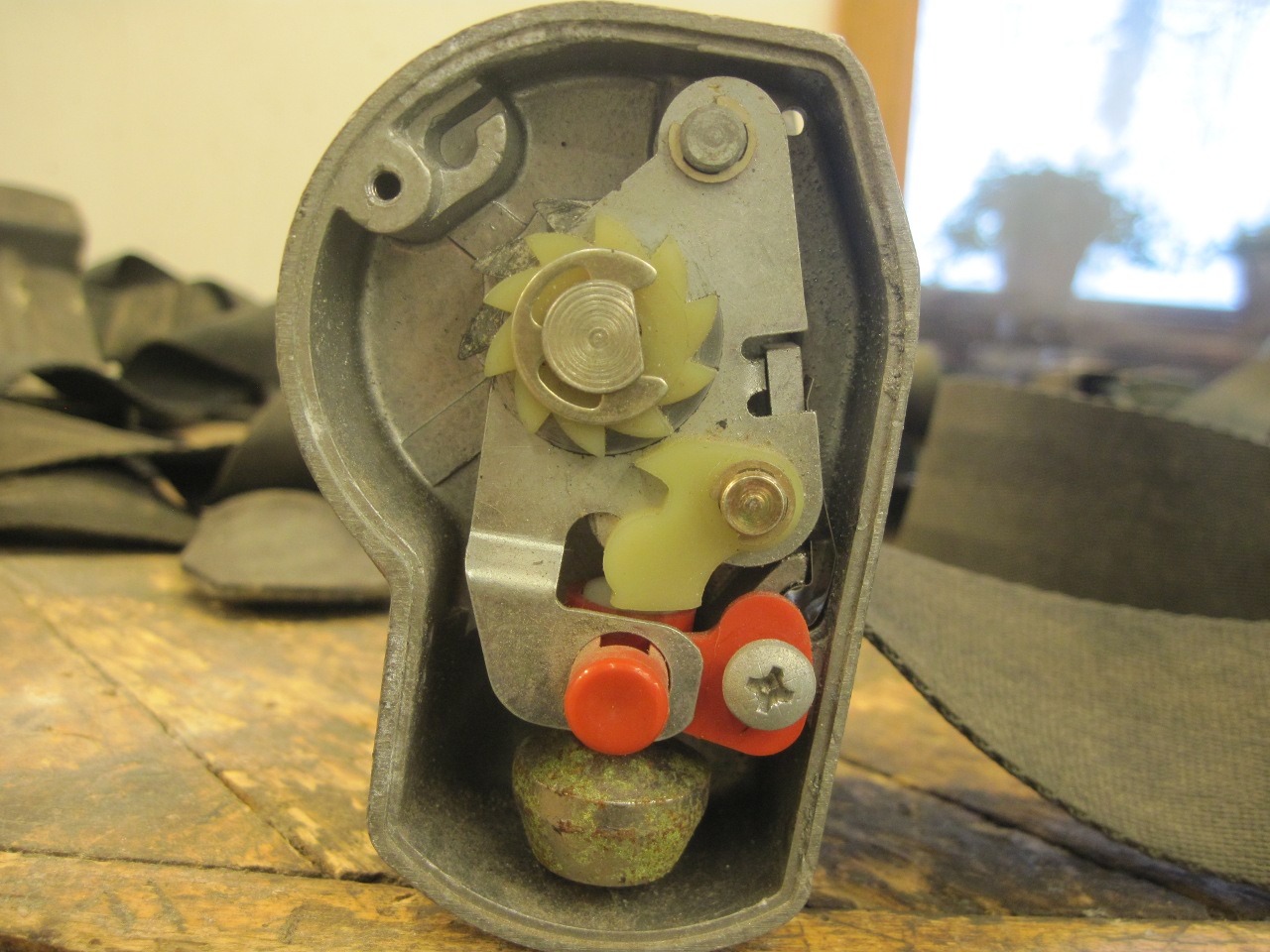
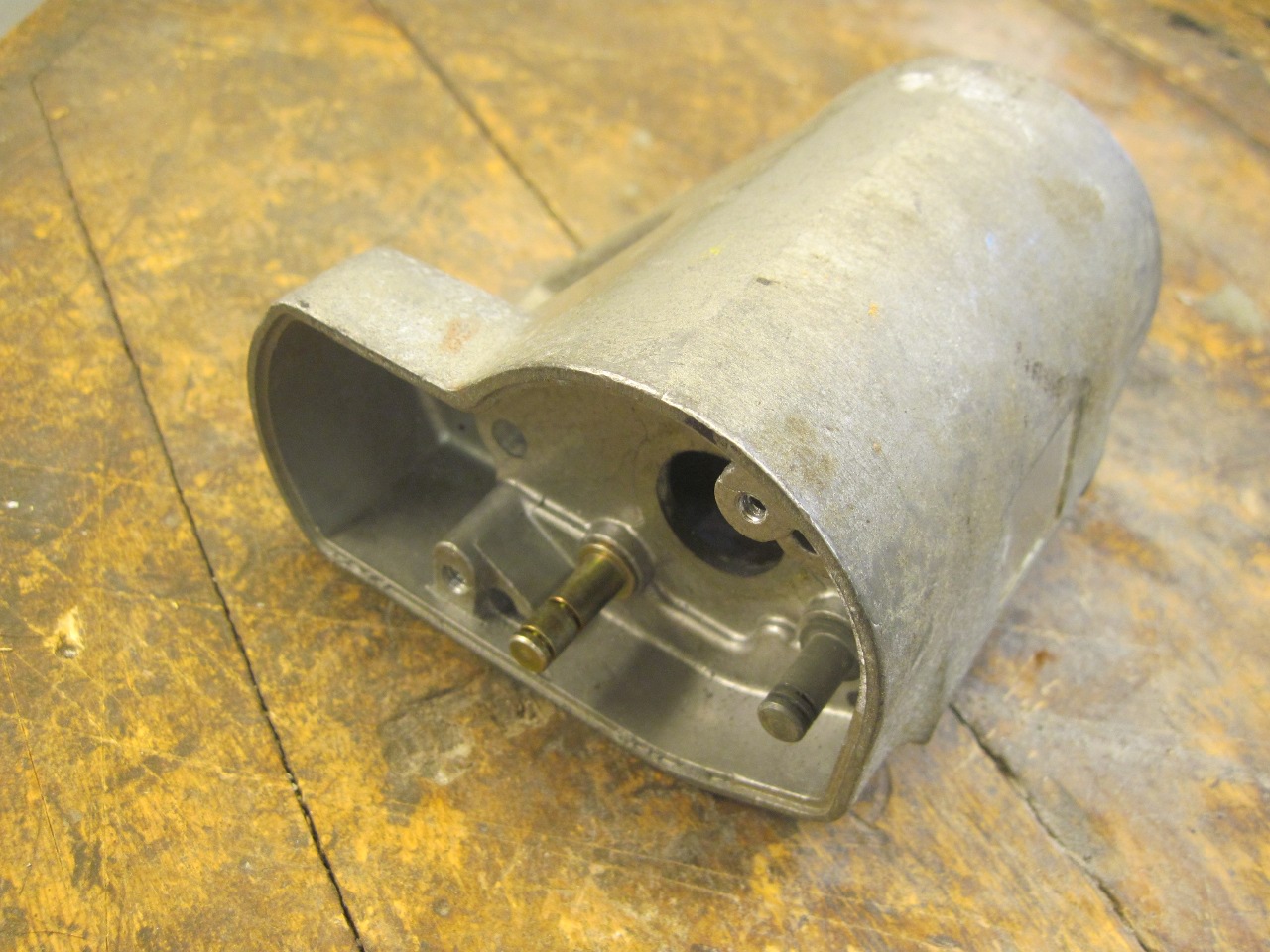
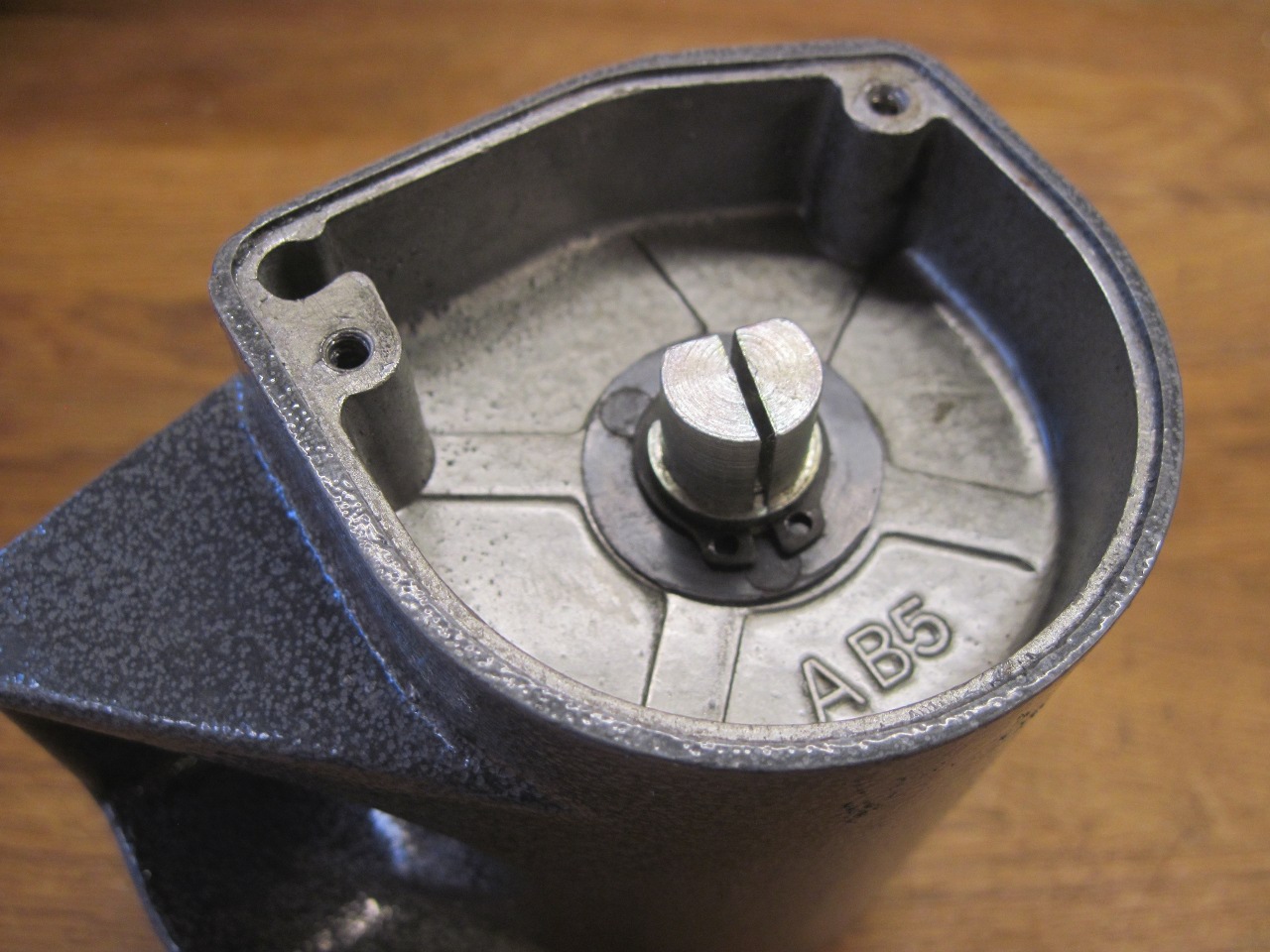
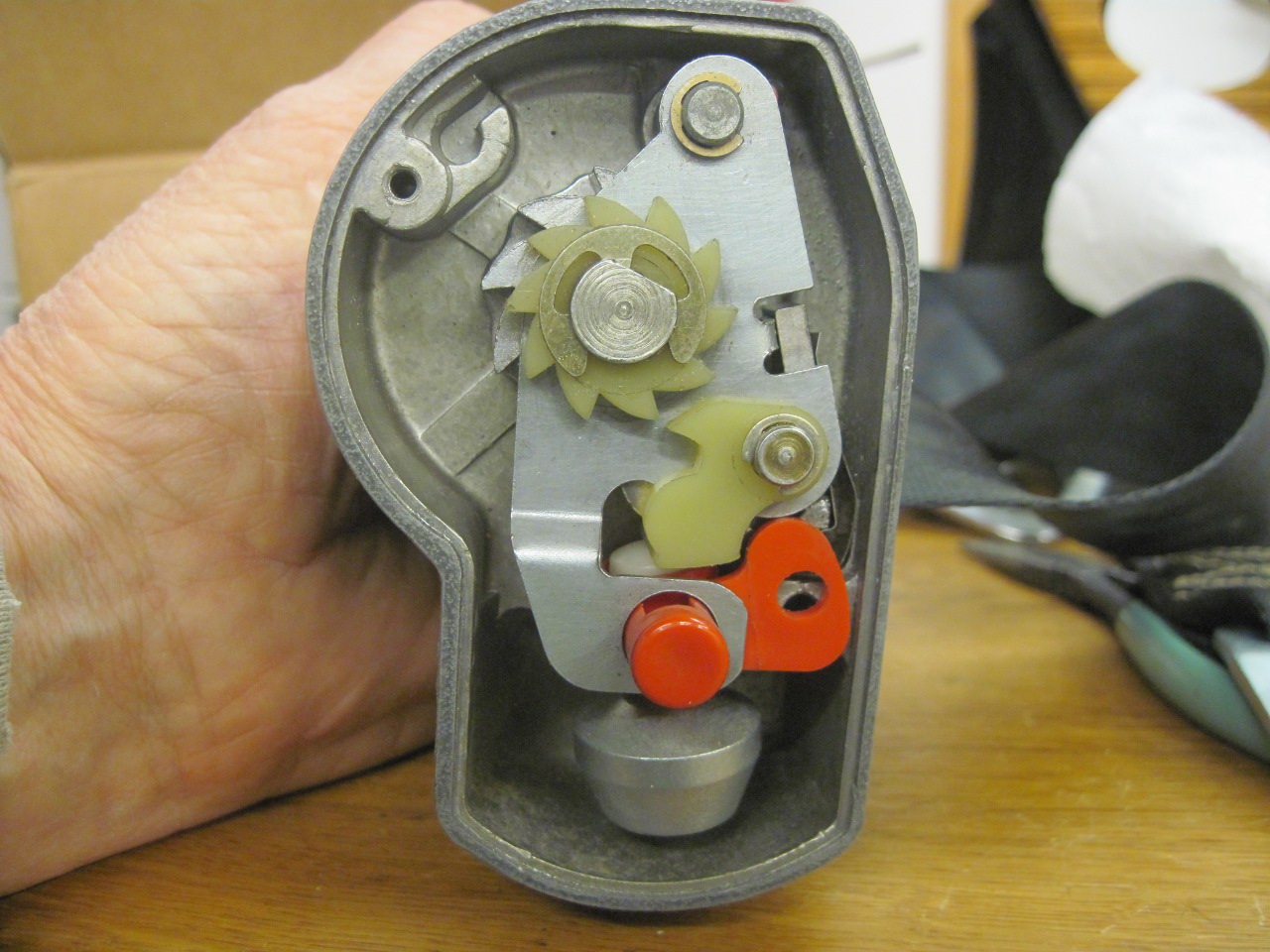
Under
the cover at one end of the unit is the sensor and latching mechanism.
The sensor is just a weight suspended from a plastic ball joint.
During any kind of acceleration, the weight's inertia will cause
it to deflect from vertical. When it does this, it slightly
raises a plastic lever so that a pawl on the lever catches one of the
teeth of a plastic ratchet gear tied to the belt reel. If there
is outward tension on the belt, the plastic gear will move the lever
further, such that it presses on a metal pawl which engages with the
main ratchet gear on the belt reel shaft.

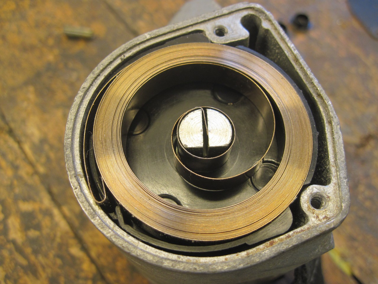
Under
the cover on the ther end of the housing is the reel spring. It is
a "constant force" spring, meaning that the torque it exerts isn't
affected much by how much it is wound up. This is due to the fact that
most of the turns of the spring are coil-bound, and only the free turns
in the middle section of the spring are active in generating force.
If I lifted my thumb off the spring, it would instantly
escape in a frenzy of exuberant springy energy.


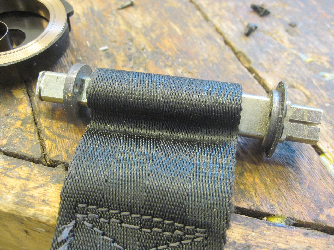
To
disarm the spring, I pulled all of the webbing out of the reel housing.
This exposes a pin that captures the end loop on the belt to the
reel spindle. Removing that pin frees the belt from rotating with
the spindle. Before pulling the pin, I put a clamp on the spindle
so I could control the unwinding of the srping. Mainly, I wanted
to count how many turns it took to relax the spring so I'd know how
much to wind the spring up in case I was lucky enough to get everything
back together again.
The relaxed spring comes out with its own little plastic carrier.
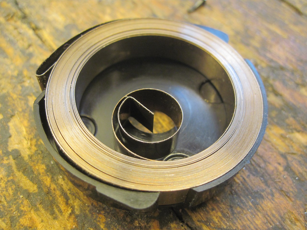
With the spring and other parts gone, the actual reel spindle can be removed.
With everything now taken apart, it was time to inspect and renew parts as necessary.
The pendulum assembly seemed mostly OK, but the weight was really corroded and had flaking plating.
With some new plating and a new tubular rivet, it looked a lot better.
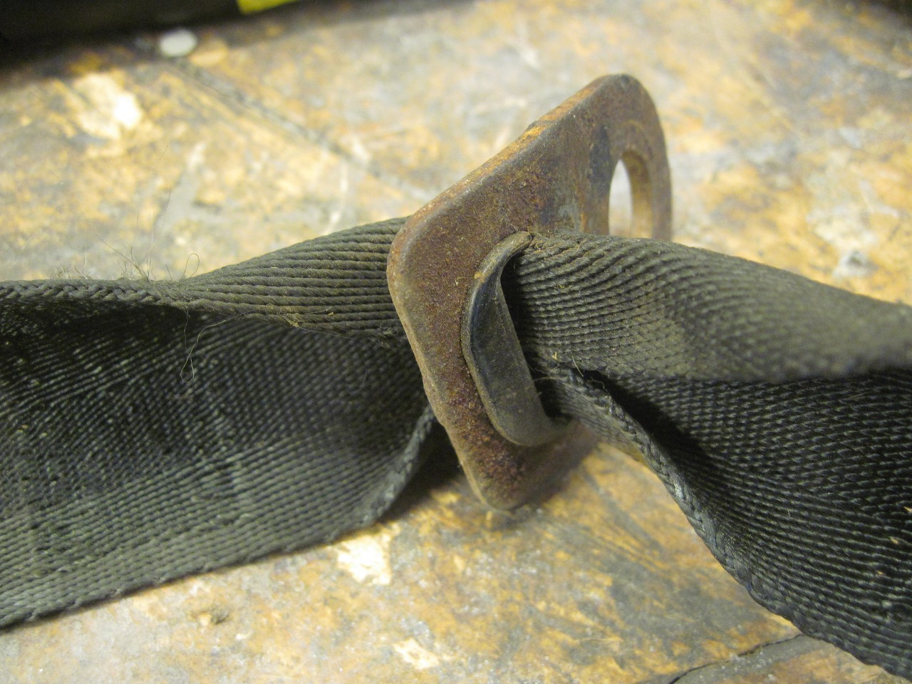
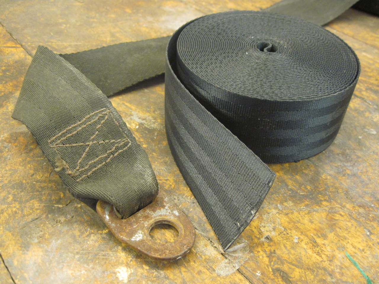
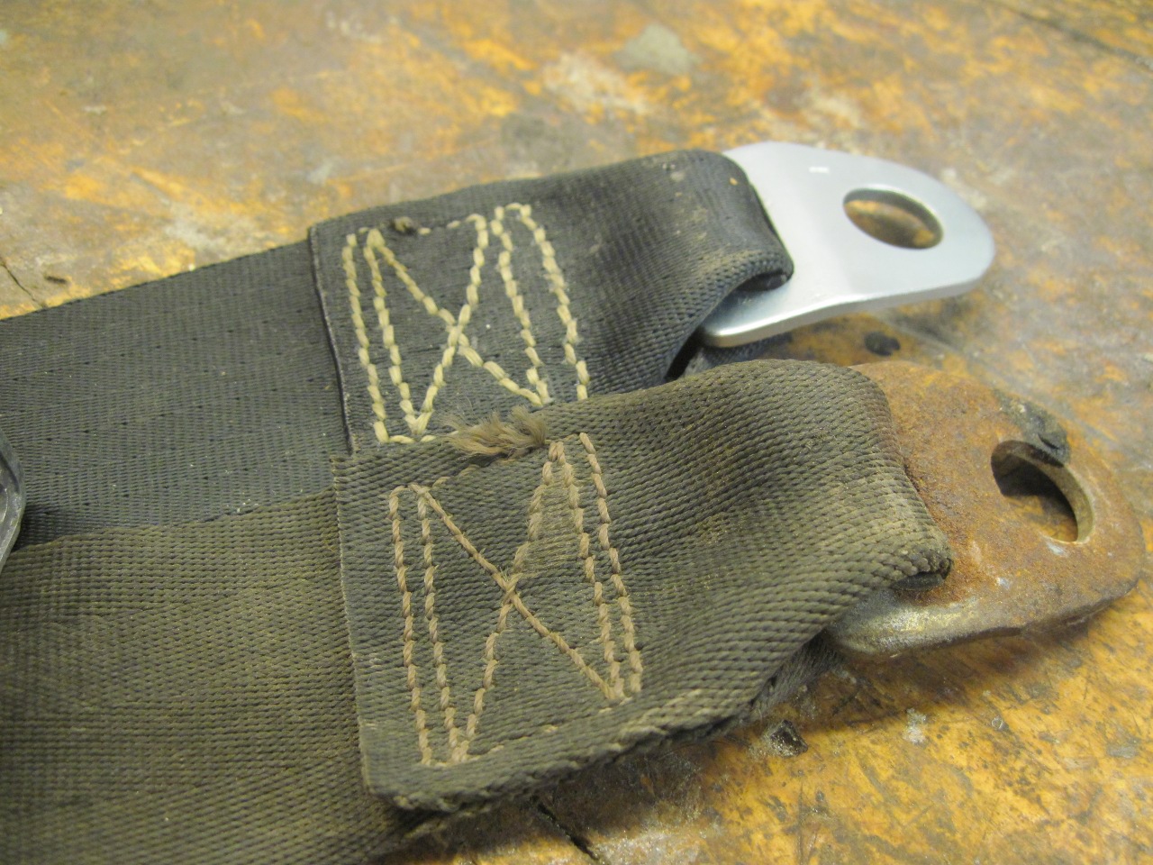
Next
up was the webbing and its various fittings. Some of the
fittings were a real mess. The worst of them were stitched into
the webbing, so the web would have to be cut or unstitched to get at
them for renewal. I unstitched the end fitting since I hadn't decided whether I was going to try to reuse the webbing.
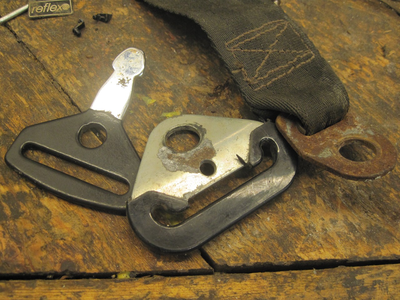


The fitting cleaned up and plated nicely.
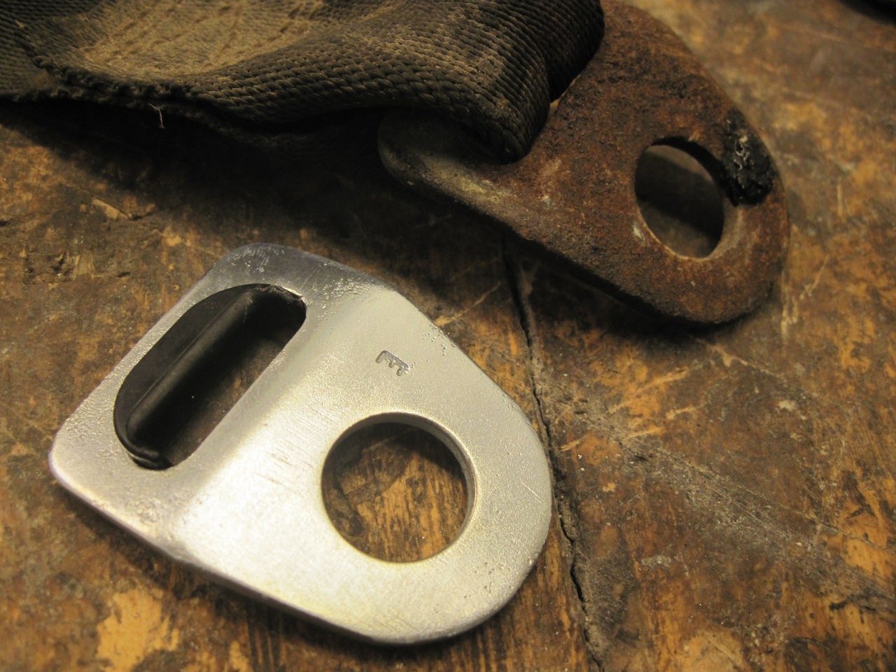
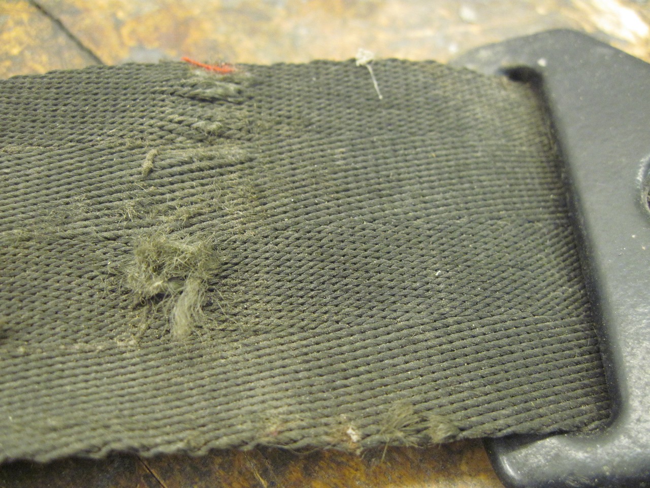
On closer inspection of the webbing, I really had no choice. It was dirty and faded, and in places, it was pretty worn.
So I bought some seat belt webbing. Now the only problem is that I don't sew.
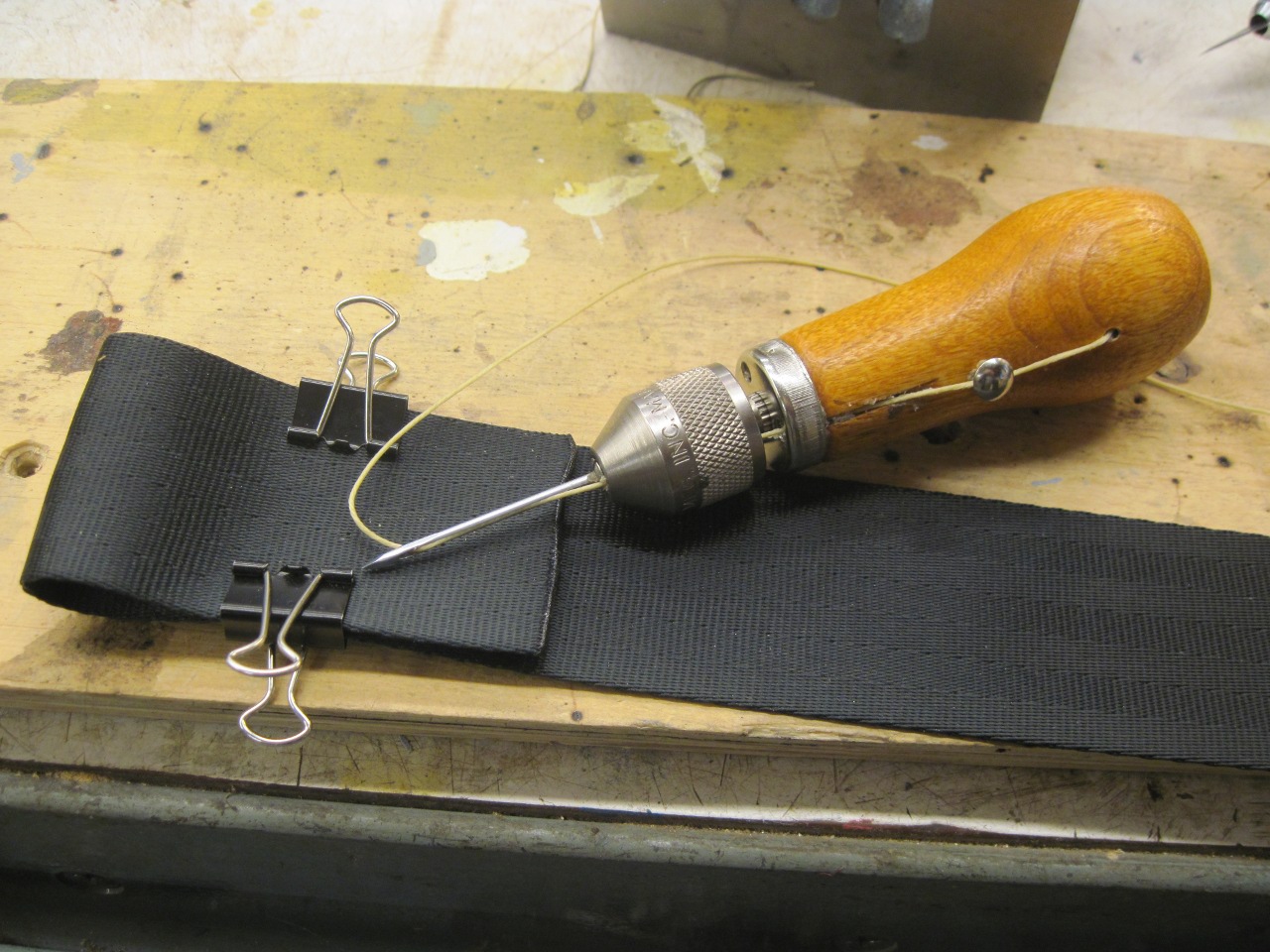
Well,
I didn't sew, but I guess I do now, sort of. I didn't really want
to invest in a sewing machine, especially a heavy duty one man enough
to sew multiple layers of this webbing. Some research revealed to
me that sailors sometimes have to repair their canvas sails without
benefit of a machine, and there may even sometimes be places on a sail
that a machine can't reach. In these cases, they are forced to
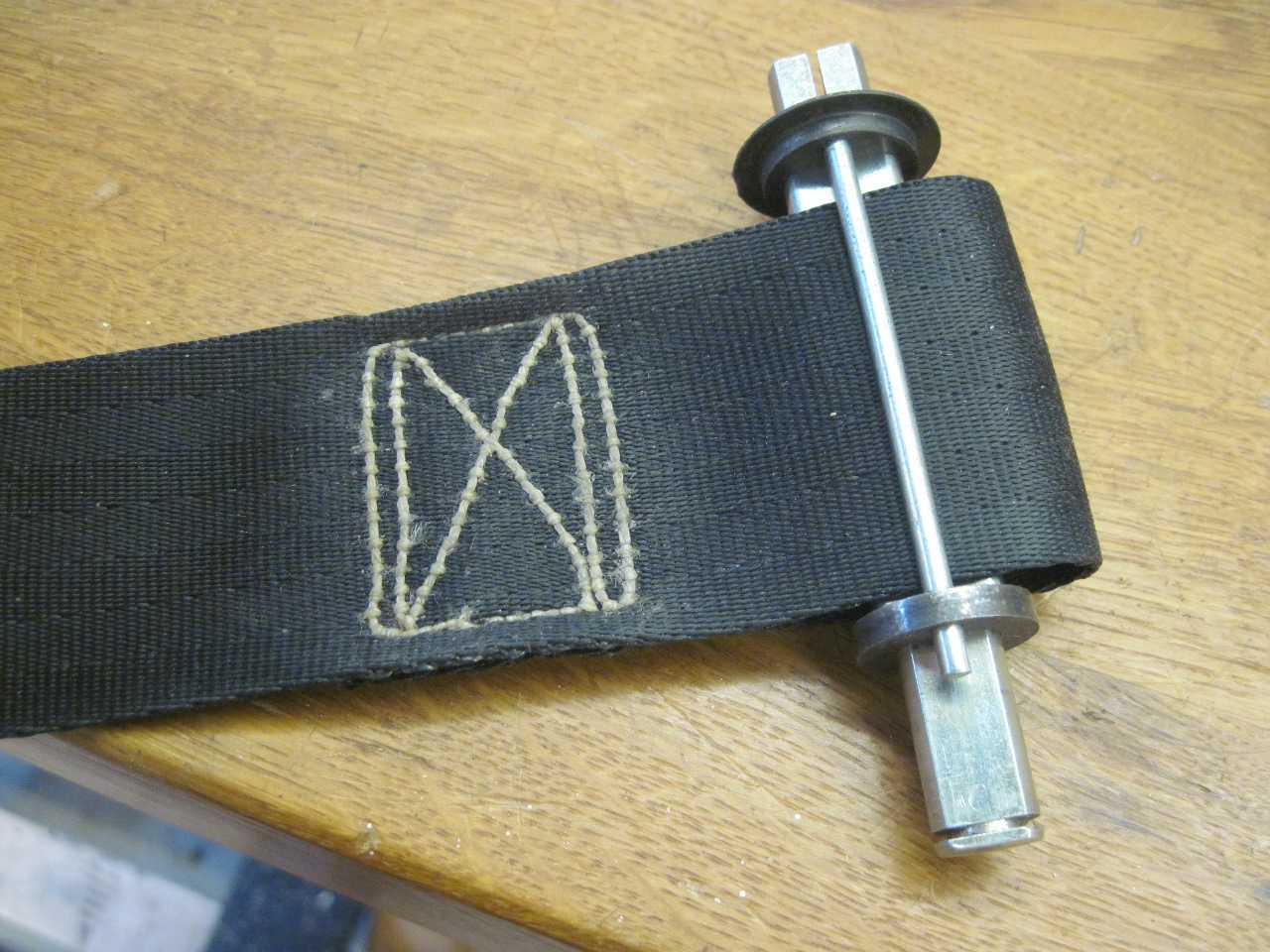
revert to the ancient art of hand stitching. Pictured below is one
tool apparently popular in sailing circles. It makes a lock
stitch, just like a machine, but slower. I sewed up a few
practice pieces and eventually decided that I was certinly no Betsy
Ross, but I could make a strong seam. I definitely got better as
I went.
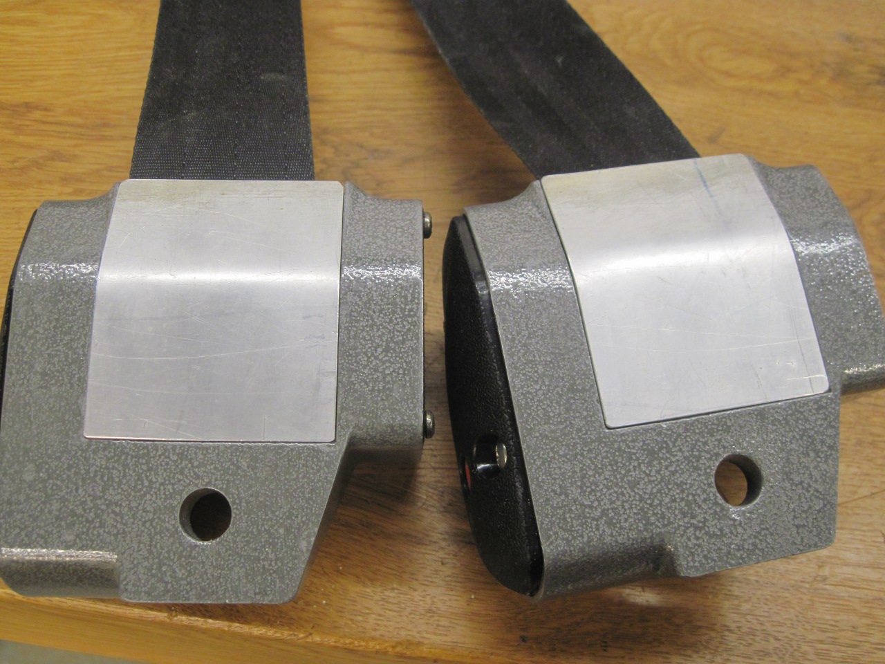
So
with most of the component parts renewed, it was almost time to
reassemble. Just needed to make the main housings more
presentable.
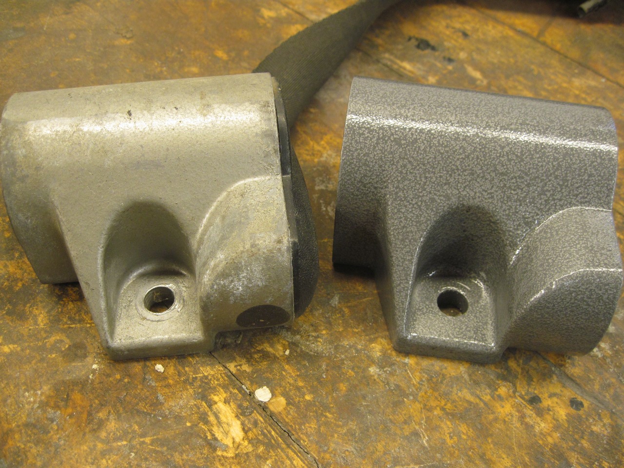
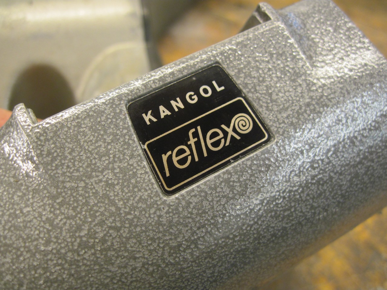
I
bought some silver hammertone powder coat powder. It turned out
to be darker and more contrasty than the original hammertone paint, but
I'm not going to fret about it.
I was even able to clean up and reapply the original manufacturer's logo.
Installed the spindle and the spring and cover plate.

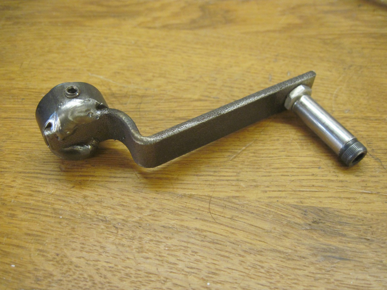
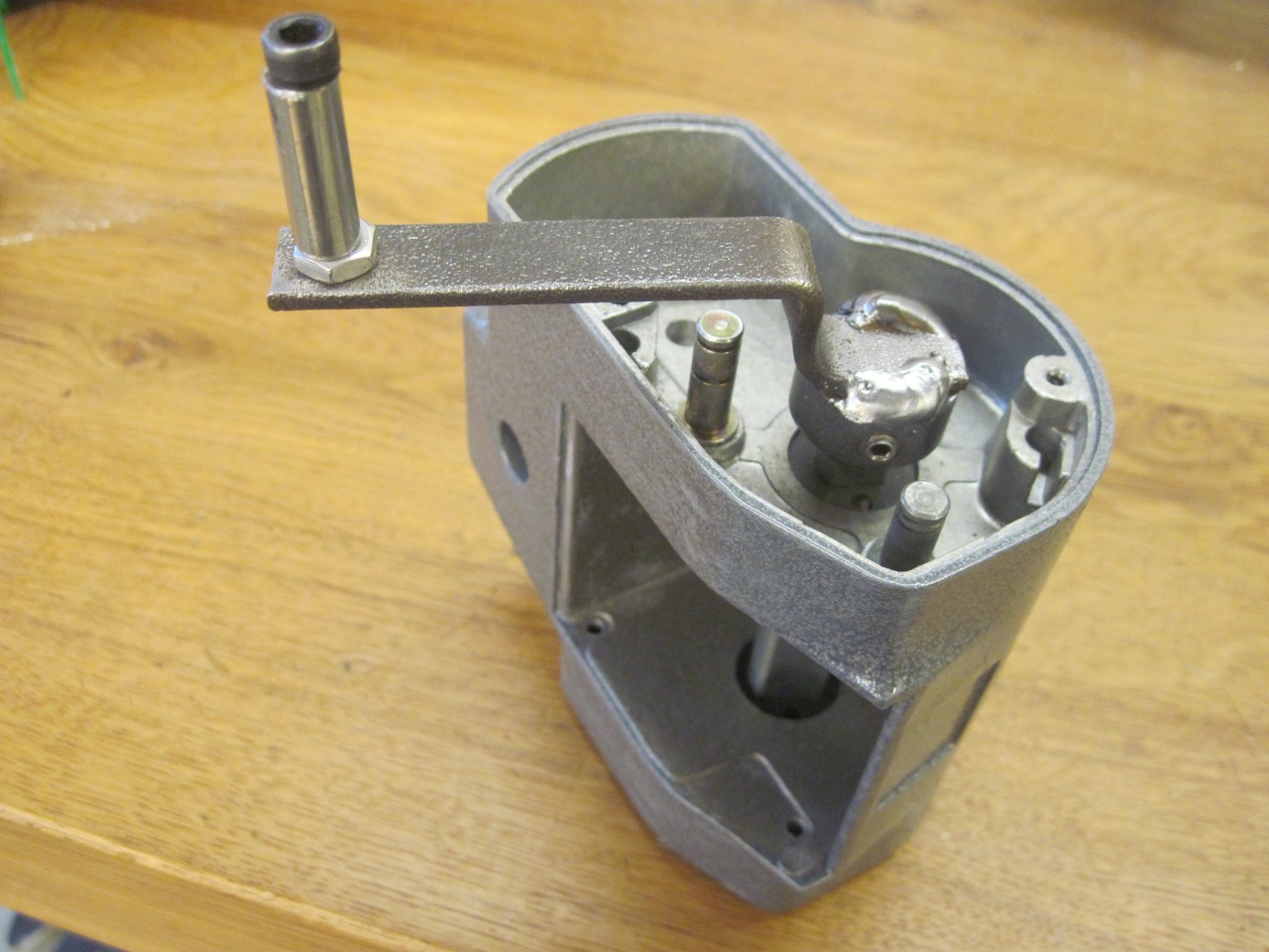
Then,
to wind up the spring, I made this little crank thingy that fits over
the end of the spindle. The picture doesn't show it, but the end
loop of the webbing has to be installed on the spindle before
tensioning the spring.
I
gave the spring about 20 turns to wind it up, inserted the keeper pin
to capture the web, and let the web slowly wind back onto the spindle.
It only takes about 12 turns for the web to fill the reel cavity
and stop.

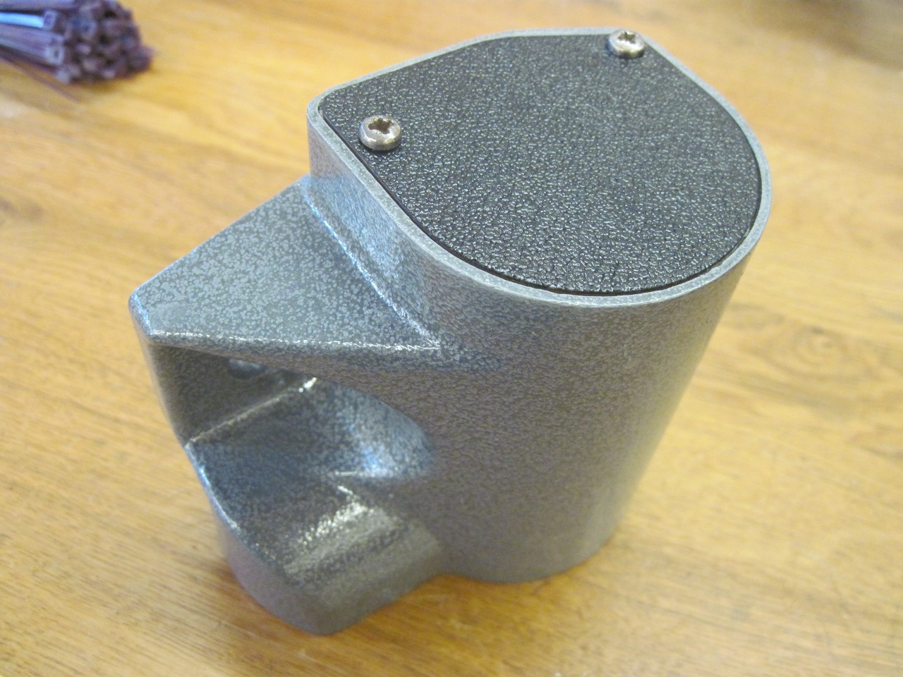
Now on to the inertia mechanism. I applied some light grease in places where I found dried up grease on disassembly.
Put
the cleaned up cover back on, and this dude is pretty much done.
I still wonder why the mfr made that red plastic piece looks so
much like a pushable button.
Now just have to do the other one.

I
realized after I was done with both units that there was originally a
plastic cover piece on the back side of the reel housing. I found
the broken cover in the bottom of the box the belts were in. The
cover attaches by a fragile little pin at each corner that fit into
tiny holes in the housing.

I'm
not sure this cover is really that necessary, but I wanted complete
closure. I made a couple of aluminum plates that fit pretty
snugly. I didn't think I could recreate the pin mounting
arrangement (that didn't really work that well anyway), so at least for
now, I just fixed the covers in place with strips of packing tape.
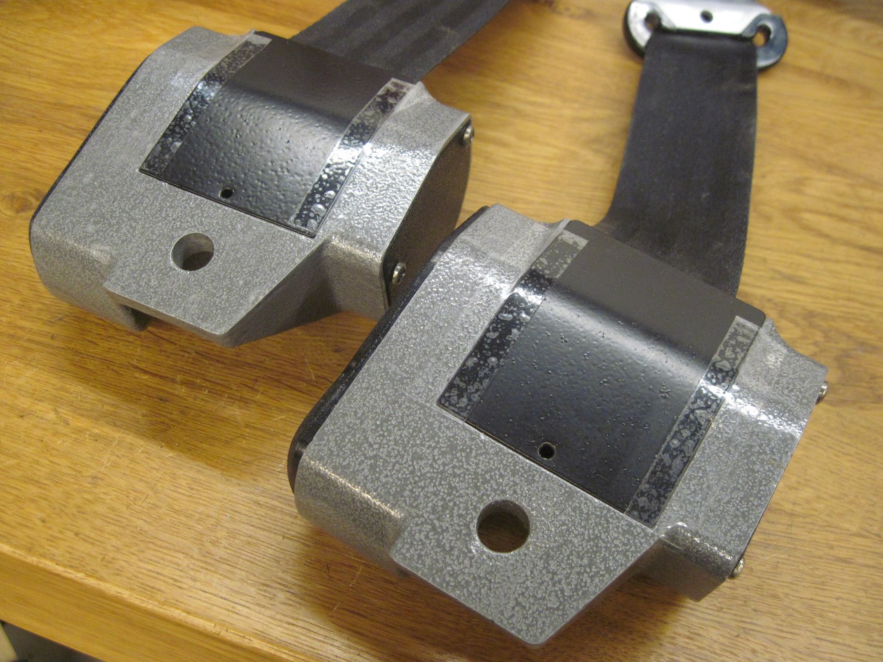
On the shelf with these guys.
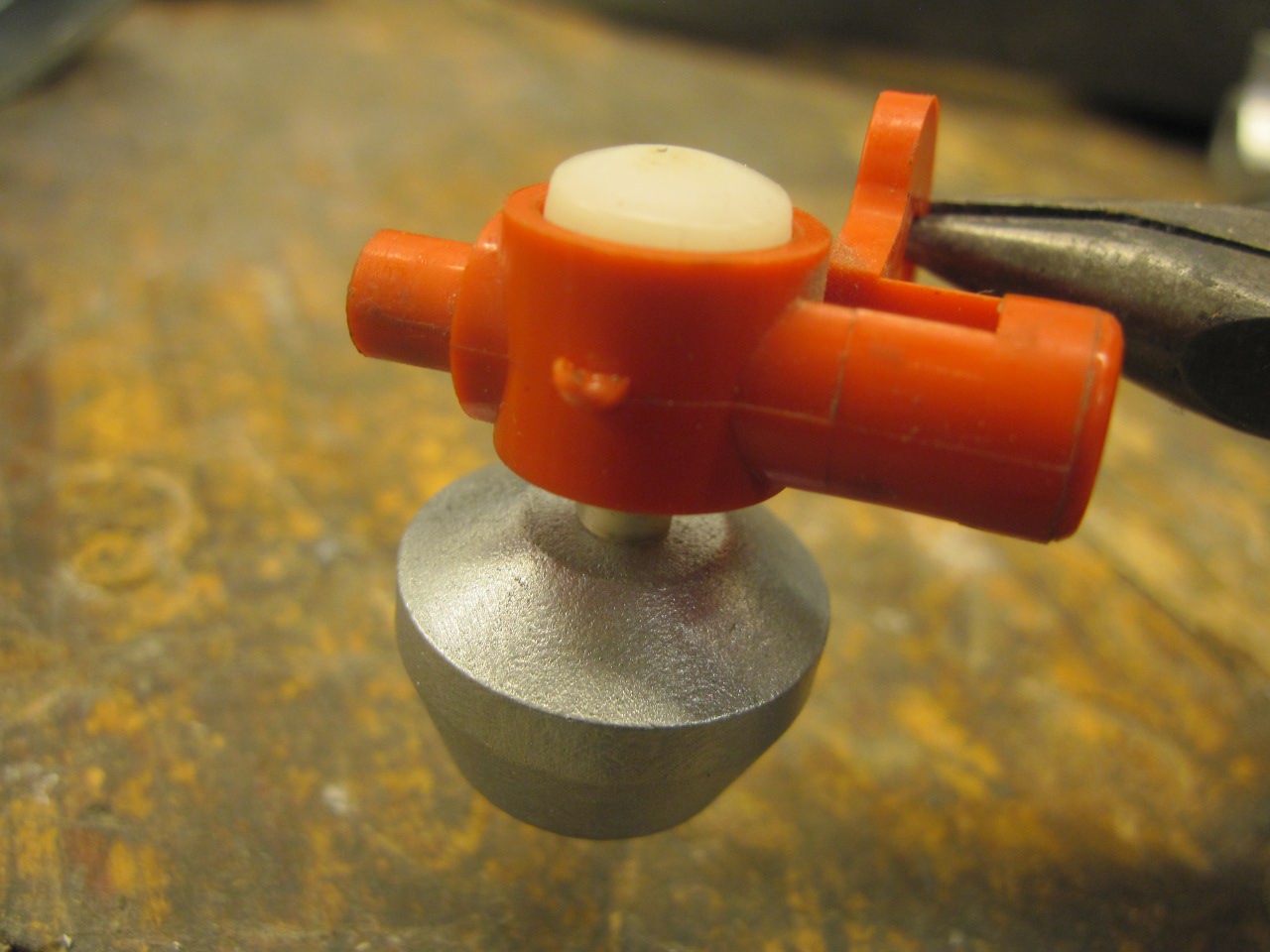
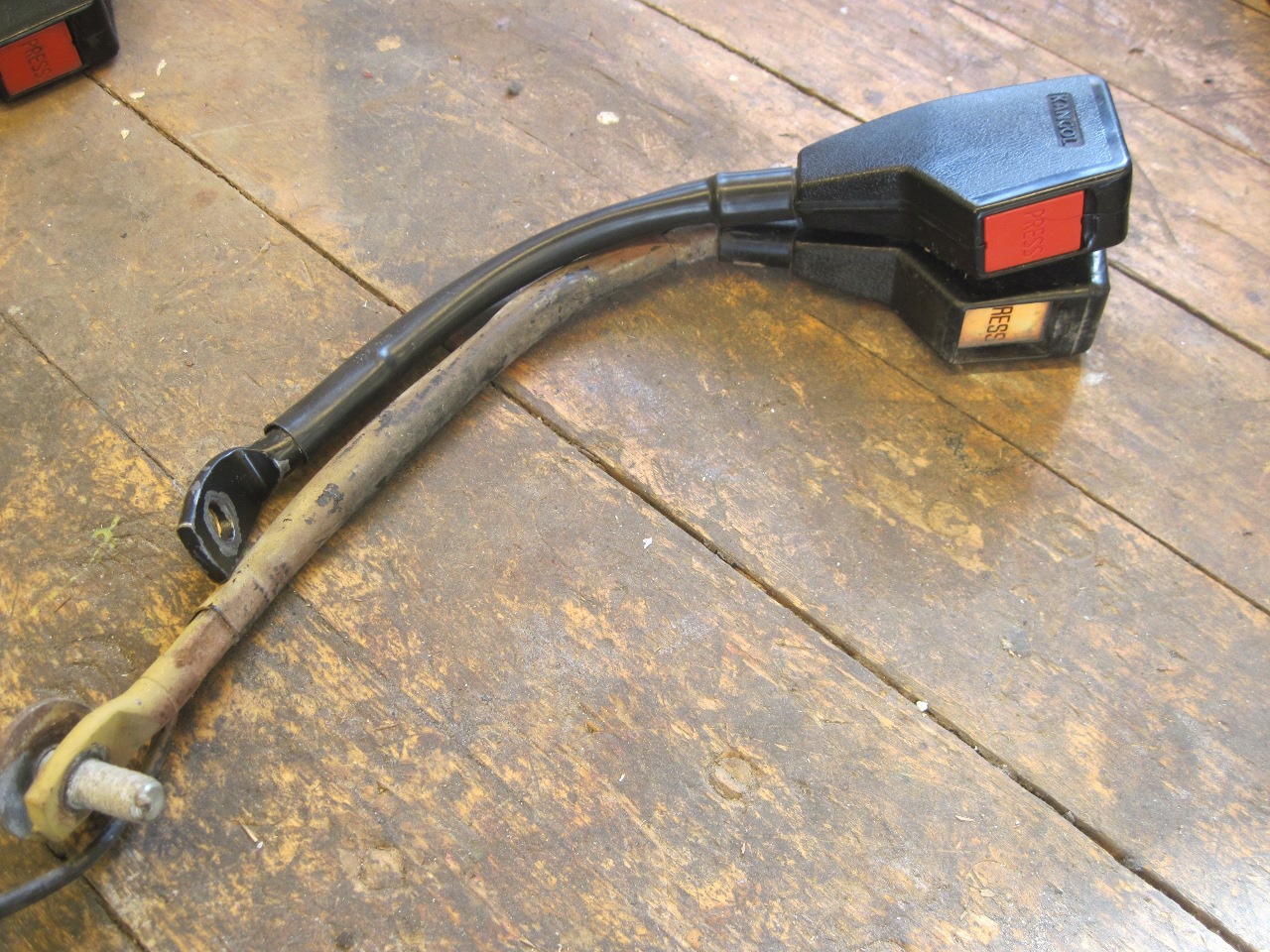
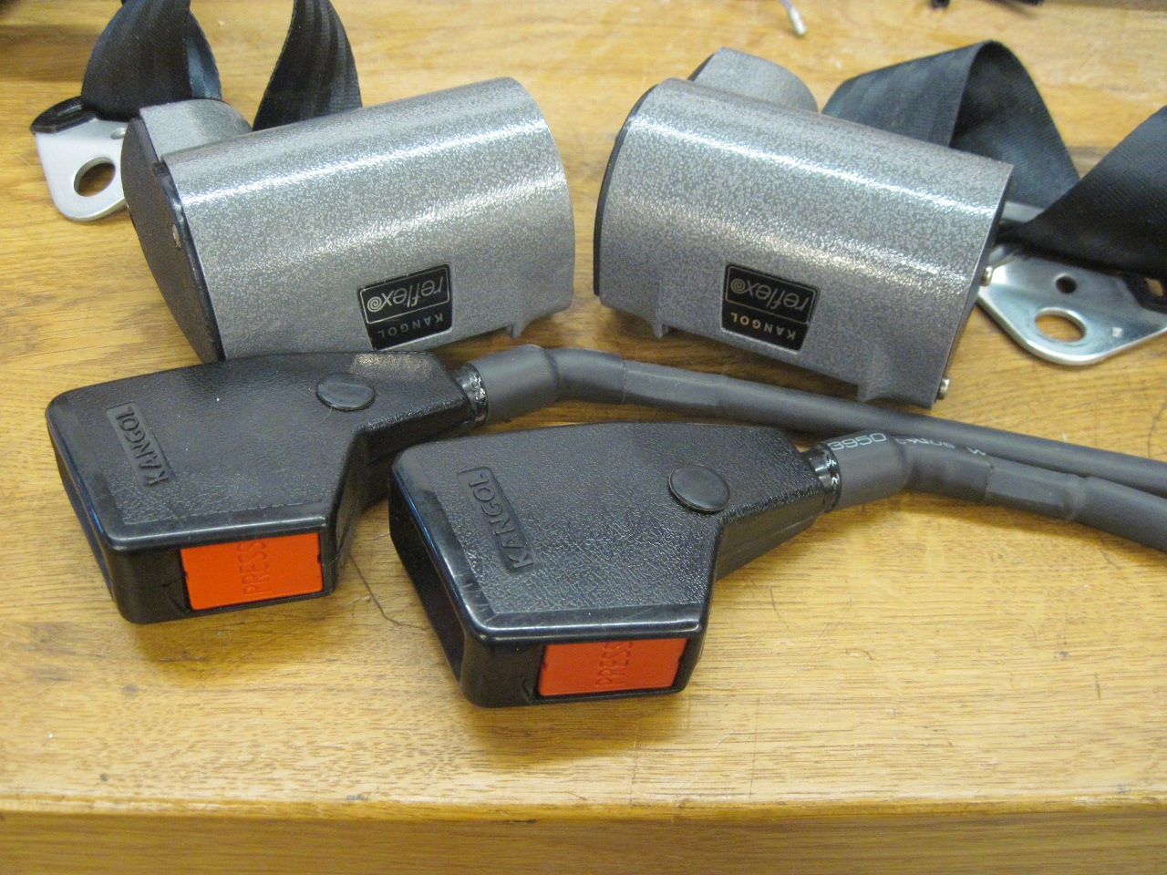
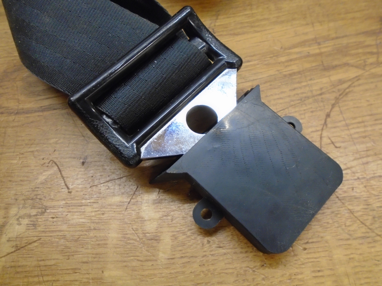
Though
the inertial mechanisms are done, there is another part of the seatbelt
system. There is a latch mounted on a stalk that sticks up on the
inboard side of each seat. The latch accepts the tang on the
seatbelt and hold it securely until the release button is pushed.
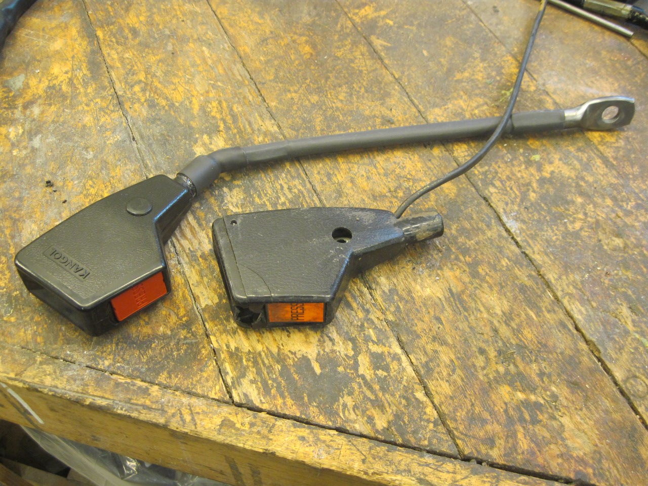
One of my latch pieces had some violence in its history.

Now
I can fix a lot of things, but I just didn't see any practical way to
fix that plastic shell. I looked online for some stalks for sale,
but didn't find any available by themselves. Next, I appealed to
the LBC community on one of the popular forums. A gracious and
generous member sent me a couple of sets of stalks.
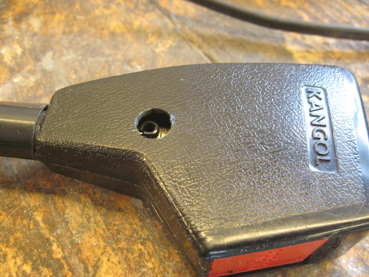
The
stalks were not from a TR6, but a Jaguar, I believe. They were
very similar to mine, but did have some differences. The most
significant difference was the actual stalk part that the latch
mechanism attaches to. The new parts had shorter stalks with a
different mounting angle.
Now
on the original parts, the latch connects to the stalk with a roll pin,
and the pin is accessible through a plugged hole on either side of the
latch shell.
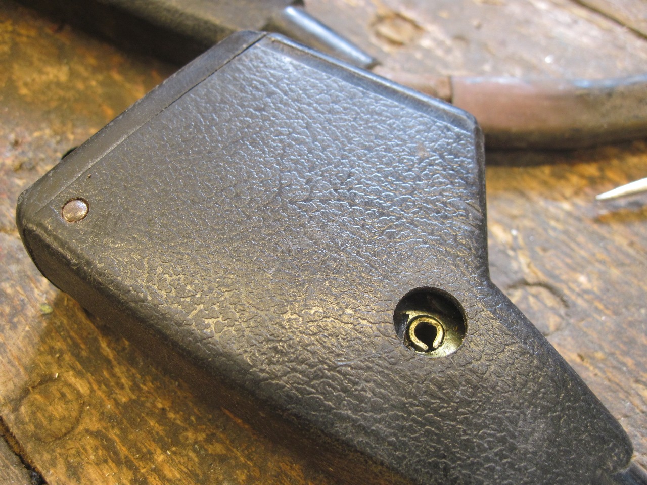

Unfortunately,
the new parts didn't have the access holes. Assuming the innards
of the new parts were the same as the old, at least in how the latch
attached to the stalk, I drilled a small exploratory hole.
Bingo--the roll pin was right where I hoped it would be. I
enlarged the hole and drilled one on the other side so I could drive
the pin out. Then attached the original stalk to the new latch
and plugged the holes with the original plugs.
Can't wait to install these.
This
was a fairly involved project, but pretty cheap. Though
aftermarket seatbelt systems are available and reportedly work well,
I'd probably do this again given the chance. At least my sewing
would be better on the next one.
Update: May 19, 2018
Seatbelt Parkers
Pawing through one of the few remaining boxes of random parts, I found these.
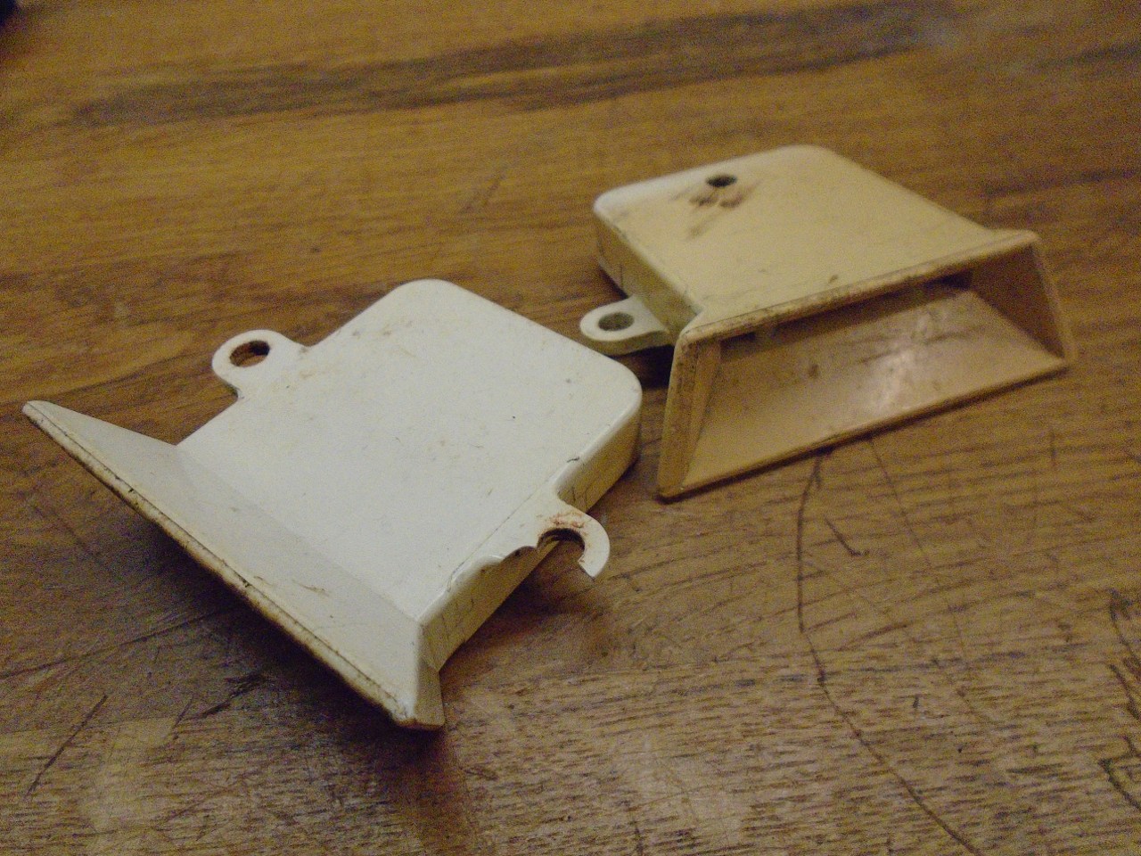
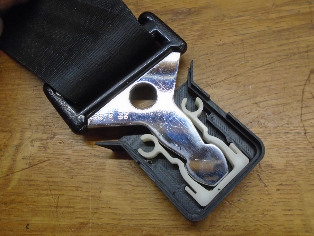
It
was a mystery at first--I didn't recognize them at all. It turns
out that they are seat belt "parkers". They screw to the inner
sills on either side of the car, next to the seats. They were
there to accept the tangs of the seatbelts to keep them handy. I
can't remember ever using them, but since I had them, I thought I'd see
about fixing them up.
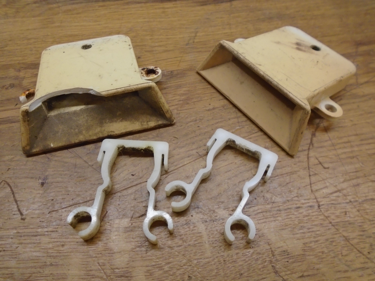
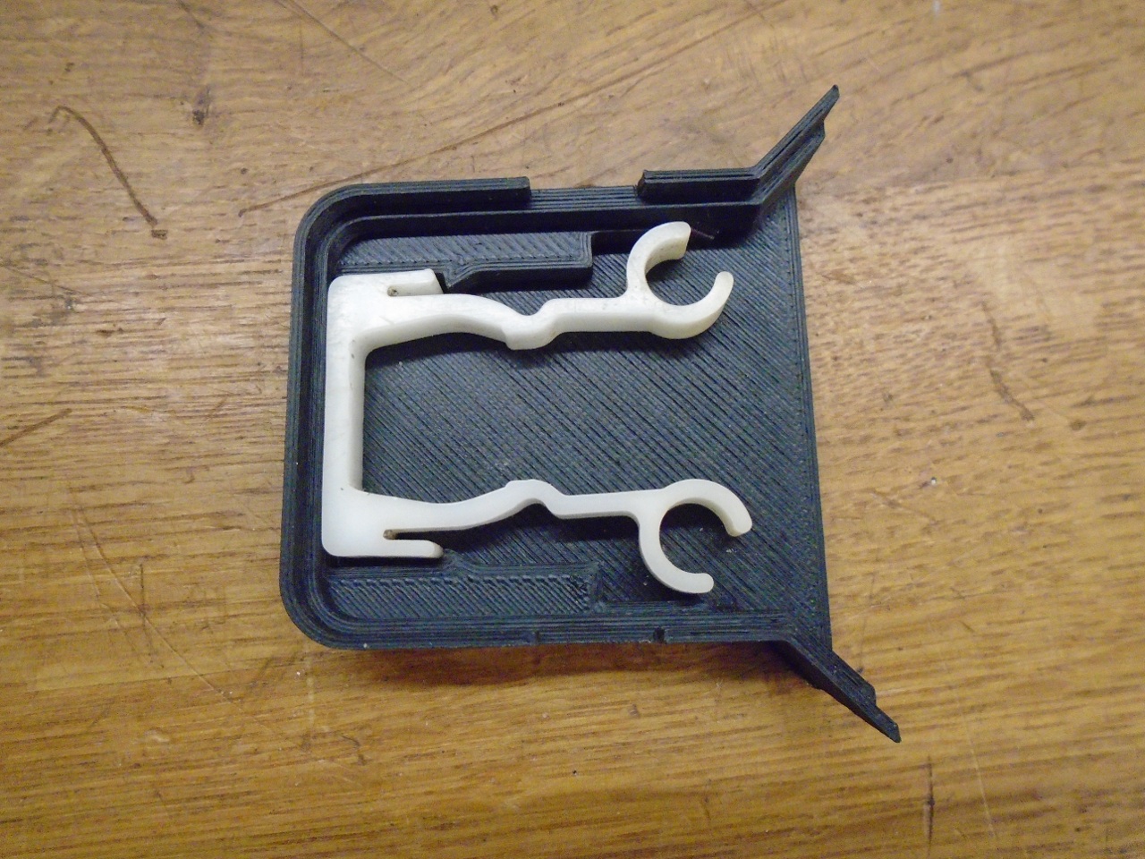
Inside
each white plastic housing was a plastic spring. The springs were
retained in the housings with little tabs with pips that fit into the
holes seen near the bottom of the housings. I depressed the tabs
to remove the springs, and promptly broke both of them off. At
this point I was already considering making new housings, so I chewed
away at one of the parts to get better measurements from the inside.
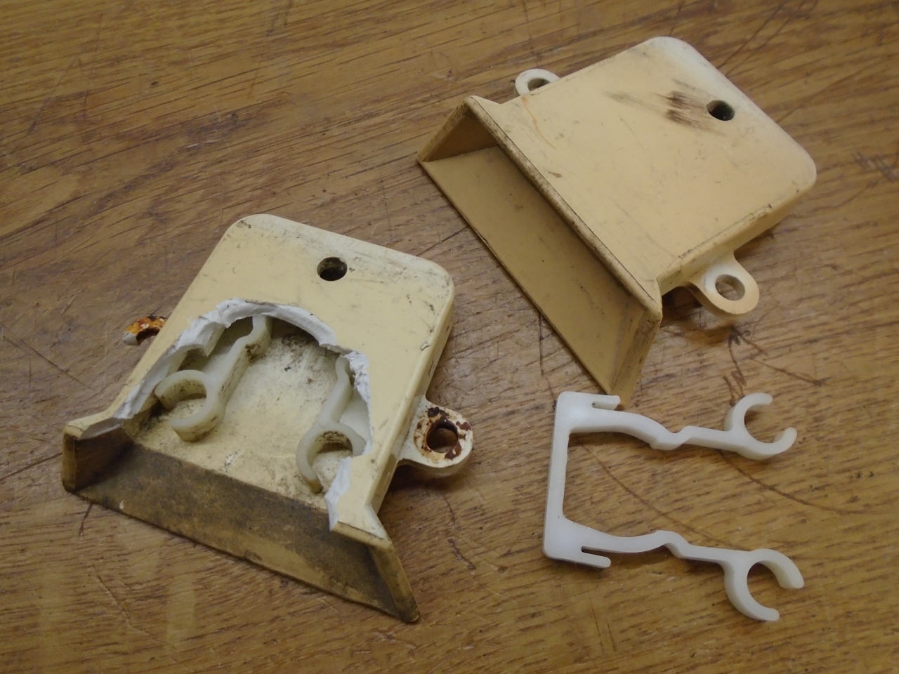
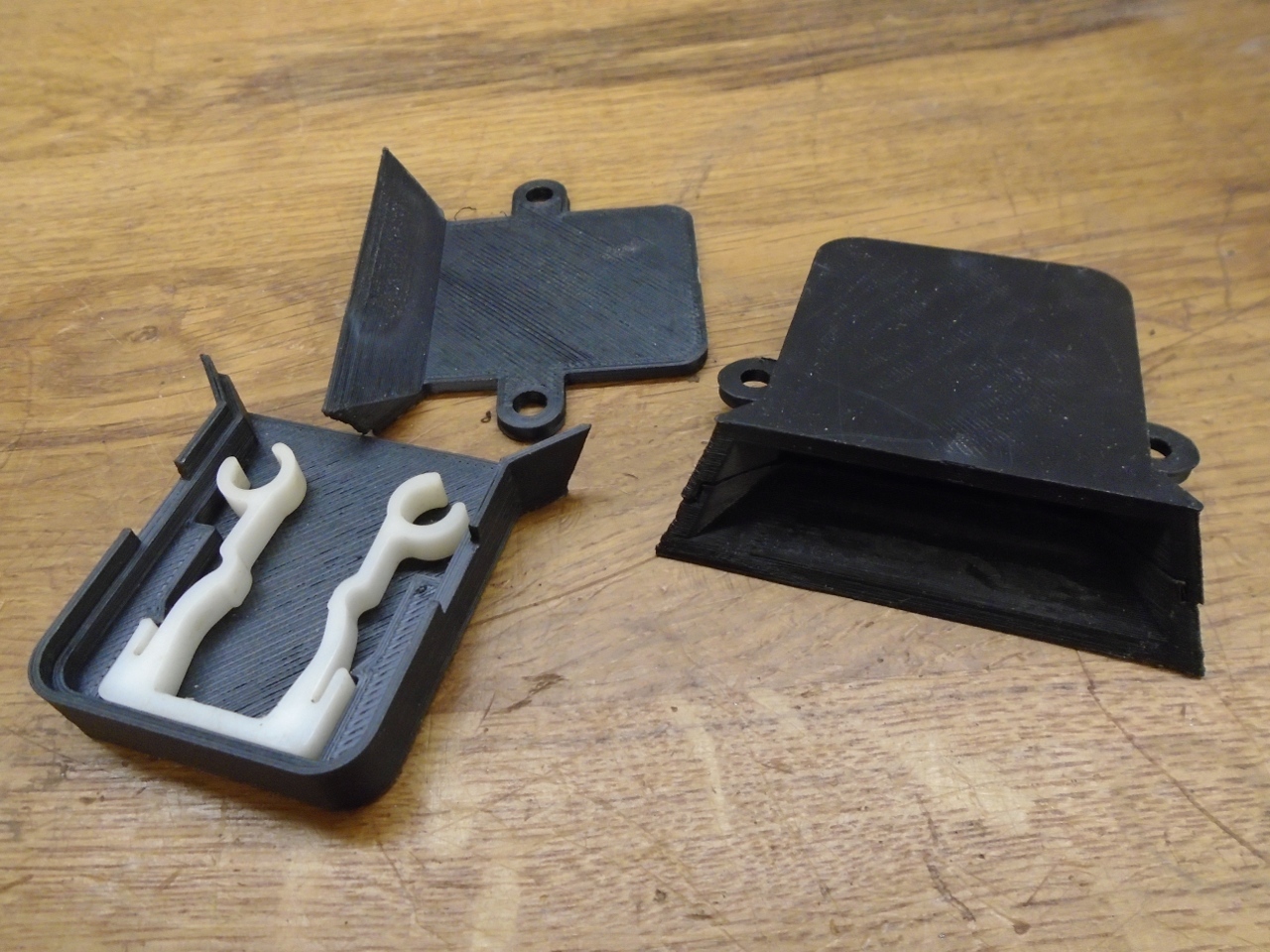
This
seemed like a good application for 3D printing, so three or four
iterations later, I had some printed ABS housings that matched the
originals pretty closely. The new housing is in two pieces that
will be glued together. I re-used the original springs, but
had to retain them in a different way since the tabs were missing.
The last pic is the housings snapped together, but no cleanup of
the edges yet.
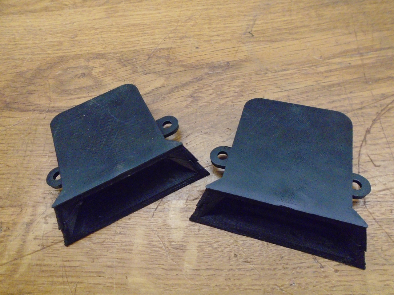
Looks like they are going to work OK.
This
little exercise was more about learning CAD and 3D printing than car
restoration, but unlike much 3D printing, it produced something at
least marginally useful.
Comments to Ed at elhollin1@yahoo.com
To my other TR6 pages