To my other TR6 pages
January 14th, 2017
Fuel Tank and Tank Vent
[Click the pics for a better view]
Continuing with the program of bolting things onto the naked car, I dragged the refurbed fuel tank
out of the shed. Before shoving it into its resting place, I
noticed the unreasonable number of superfluous holes in the floor under
where the tank goes.
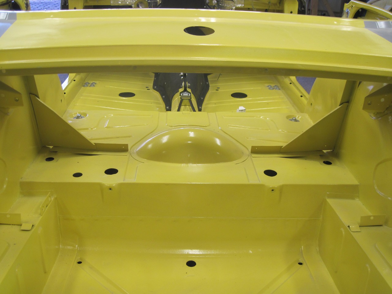
One
hole was of course for the fuel line to the engine bay, and another
probably for the vent line to the charcoal canister. I wasn't
sure what the rest were for, but it didn't seem wise to leave them
open. I measured the holes, and bought a few bags of rubber plugs
that took care of the problem forthwith. I only left the fuel
line hole since I won't be installing the charcoal canister. More
on that later.


The tank gets a lttle foam donut to seal around the hole the fuel line passes through.
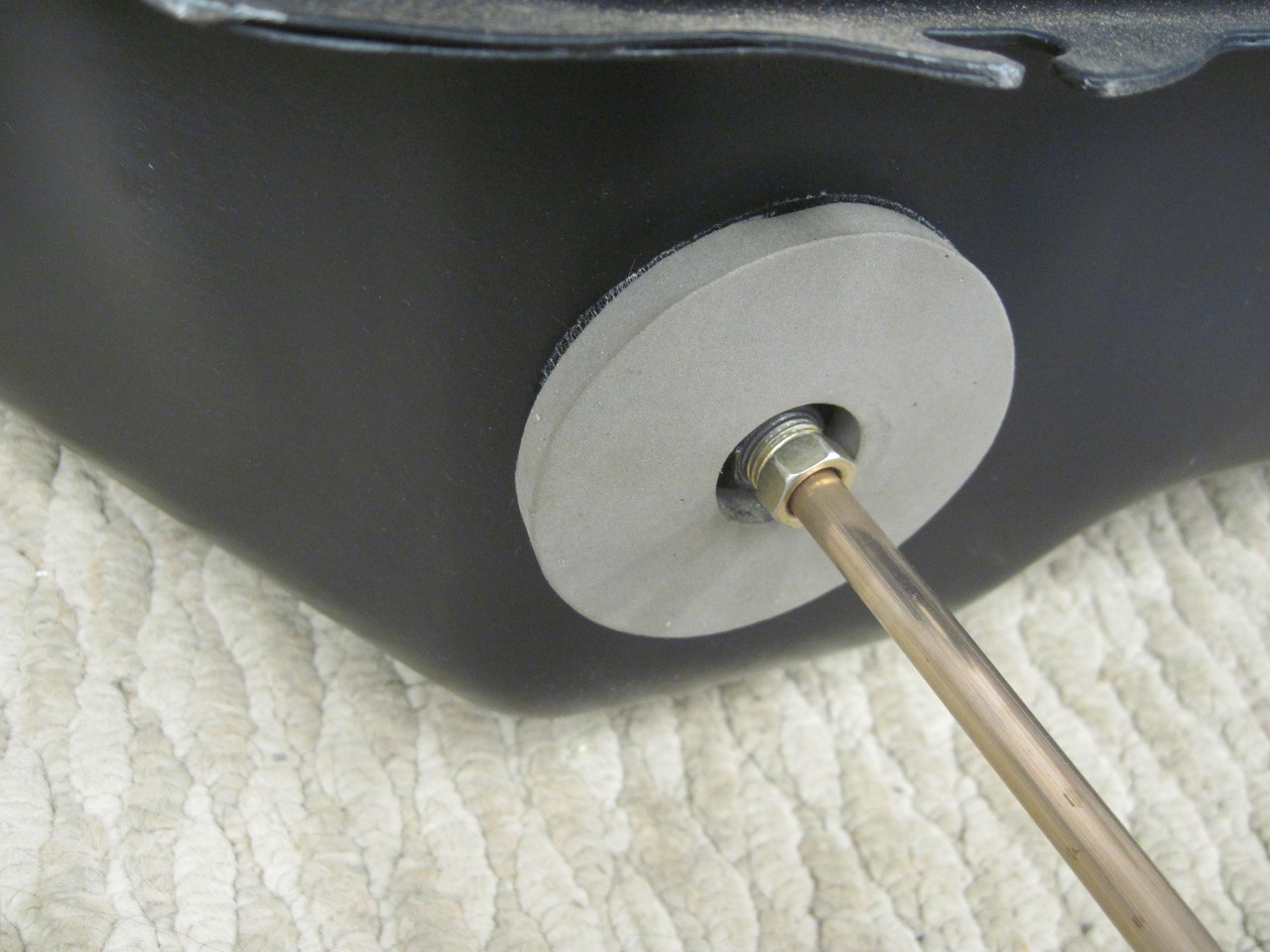
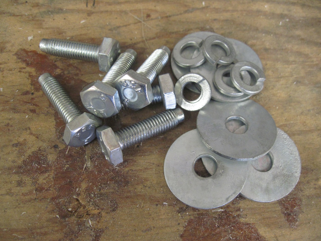
I
gathered together all the replated original mounting hardware.
Original except for the lock washers, that is--those are new.
Installation was a little awkward, especially as a solo act, but the tank finally went home.
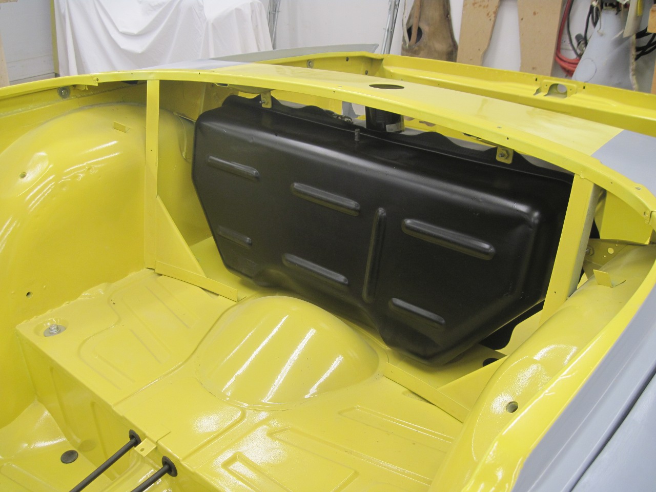
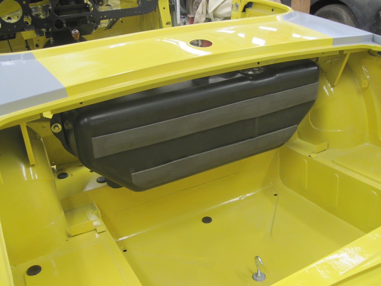
This is where I started to think more seriously about the implications of not installing the charcoal canister.
The
charcoal canister became part of the TR6 design in response to US
regulation of evaporative emissions from vehicles. Because
of its enormous surface area, activated charcoal has the interesting
property of being able to sequester relatively large amounts of
gasoline vapor from air. In the TR6 as in many cars of the era, the
fuel tank vent as well as the carburettor float bowl vents were routed
to the canister. Since closed containers of fuel must
breathe to maintain neutral pressure, exhaled vapor-laden air is passed
through the charcoal material where most of the hydrocarbon content is
adsorbed. (It's called "adsorption"
when it is a surface phenomenon.) It is a reversible
process, and if fresh air is flushed through the material, much
of the vapor is released. This is what happens when a
canister-equipped TR6 is started. Vacuum ports on the carbs suck
fresh air through the charcoal, flushing out most of the adsorbed
vapor. The amount of charcoal in the canister is specified such
that it won't get saturated with vapor between flushes. A
saturated canister won't adsorb any more vapor.
Now
it's not that I'm pro-pollution or anything, but I don't want to use
the canister. The system has all the hallmarks of a hastily designed
bandaid. Its considerable plumbing was a common source of leaks
and stoppages that could impair functon of the engine in subtle and not
so subtle ways.
So,
without the canister, what to do with the tank vent? For decades
before the '70s, millions of cars did fine with a simple atmospheric
tank vent, typically in the gas cap. This provided a free
exchange of fuel vapor with the atmosphere. The main downside of
this, other than the pollution, is the smell. Over temperature
cycles, tanks breathe out vapor, which can make a garage smell
like a refinery.
A
little research showed that one solution for this issue is to seal
the tank, but provide a pressure relief valve. The valve keeps
the tank sealed for most normal small pressure cycles caused by
tempurature or barometric pressure swings. If for some reason the
tank pressure exceeds a set limit, the valve "burps" the tank to
relieve the pressure. On the other side of the coin, a sealed
tank will also need a vacuum relief valve, since consumption of the
fuel would otherwise create a vacuum in the tank that works against the
fuel pump. Typical relief settings for the valves seem to be
something below 1 psi for pressure, and below 0.1 psi for vacuum.
As I pondered this, my science geek side immediately siezed the moment, and began planning experiments.
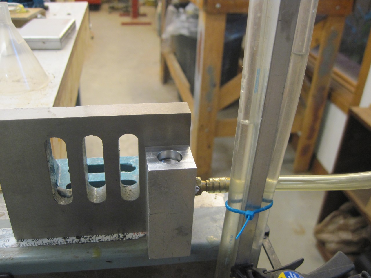
He
took a little block of aluminum and bored a flat-bottomed well in one
end, with a small hole in the center of the bottom of the well leading
to a hose barb fiting. In the well, he placed a solid rubber ball
that just fit. The ball sealed the hole in the bottom of the
well. Then, the Geek set out to see how much pressure it would
take to unseat the ball. He used a simple shop-built water
manometer to measure the small pressures. The picture shows the
block with the rubber ball swapped out for a thin rubber pad with a
weight on top of it.
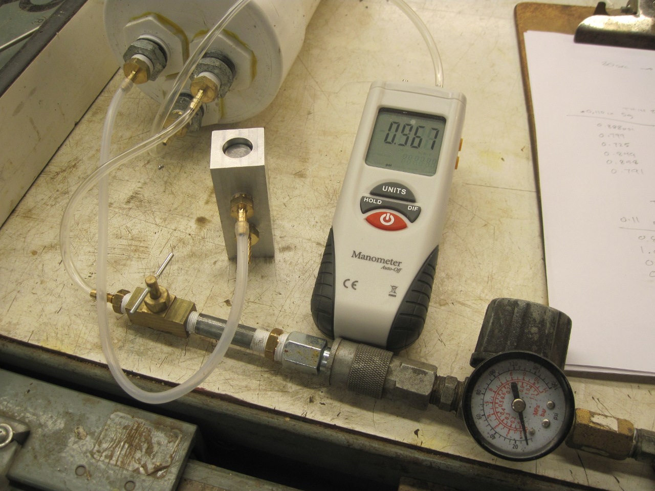
He
got some results that were pretty encouraging. He could vary the
pressure set point by selecting the oriface size and the weight on top
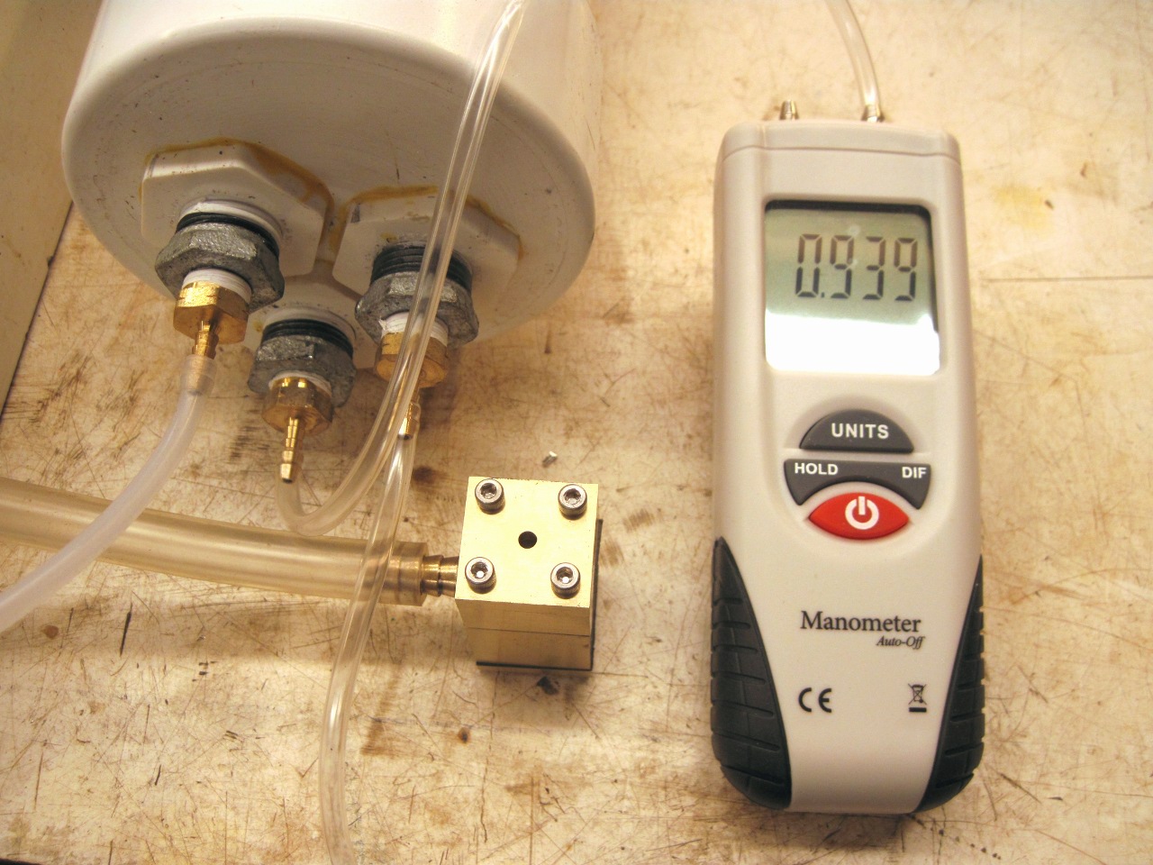
of the rubber. He was having so much fun, the geek went and
bought a proper digital manometer. The tank looking thing was to
simulate the air volume above the fuel in the gas tank. "YES!"
exclaimed the Geek, "Science Rocks!"
He
could pretty much dial in any pressure and vacuum relief points he
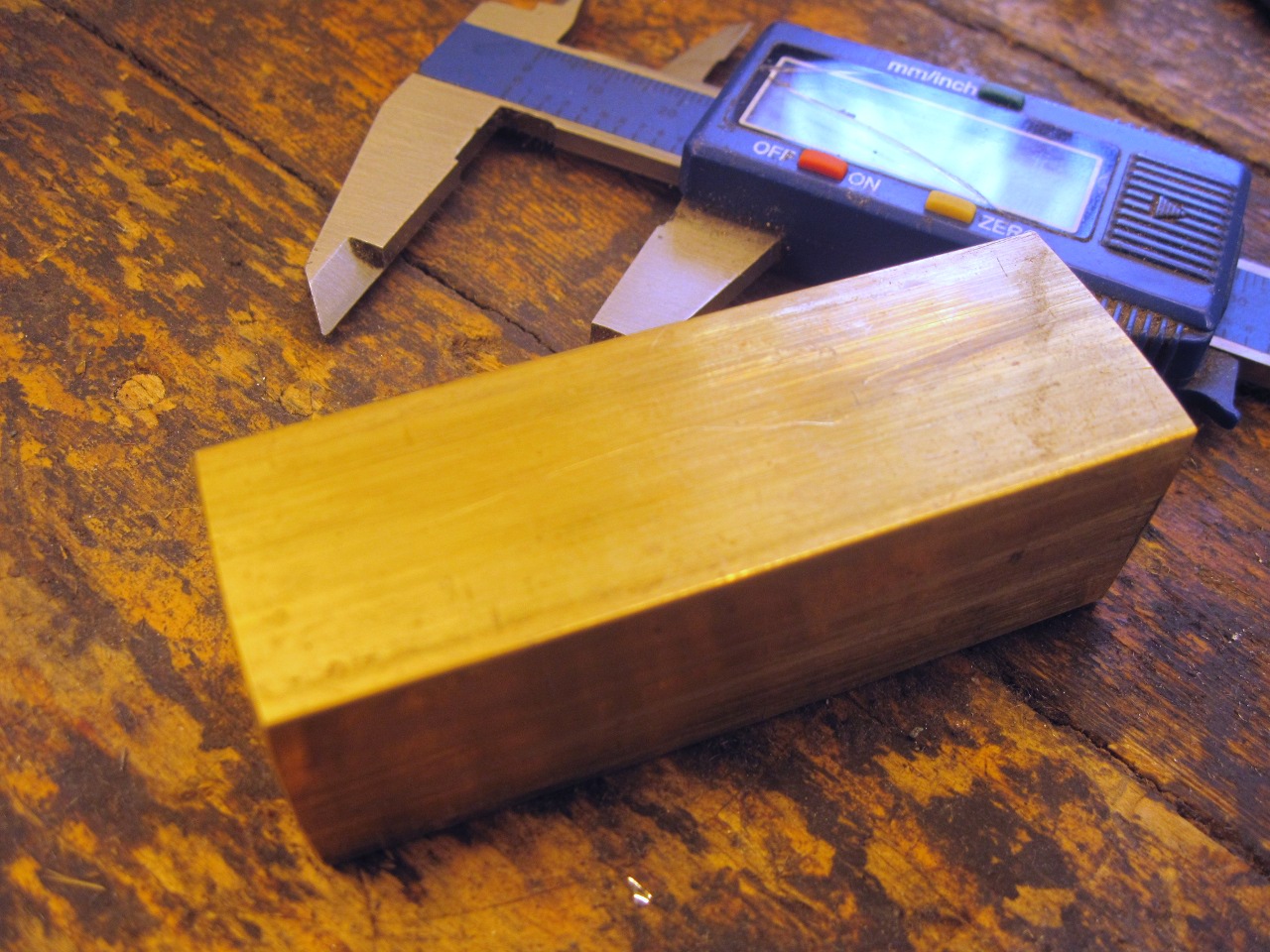
wanted, so he decided to make a real working unit with both valves.
Started with a hunk of brass, and ended up with the pieces in the
second picture. It is a stack of two relief valves--a vacuum
relief on the bottom, using an oriface and a rubber ball, is set to
about -0.09 psi, and a pressure relief on the top, using a rubber disc
over an oriface and a small weight, set to about 0.9 psi. The
tank vent connects in the middle between the two valves.
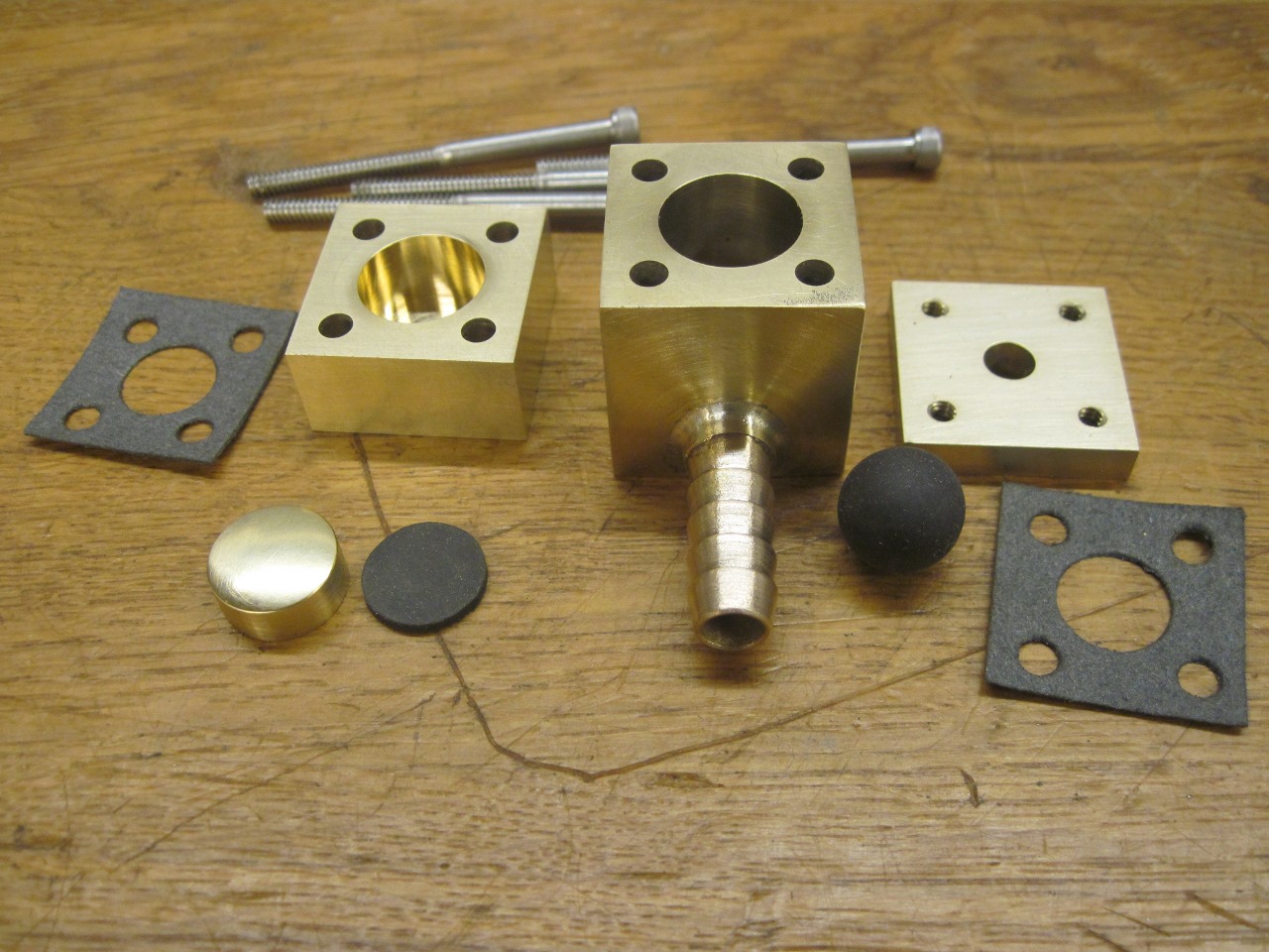

Well,
the Geek's valve came out well enough that I decided to use it, but had
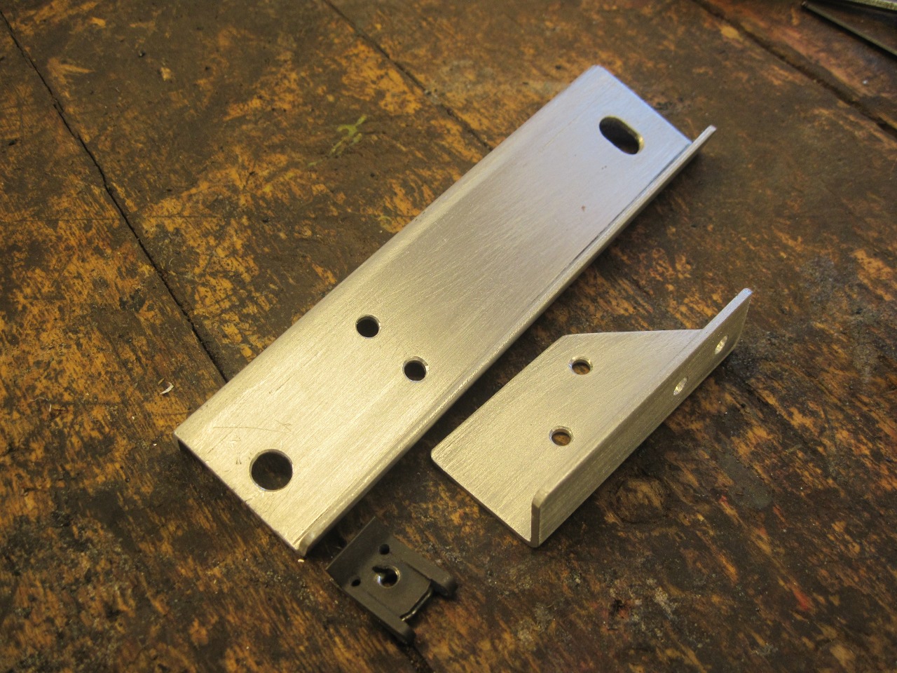
to figure out how to mount it. I made a little flanged piece of
aluminum and spanned it between the left top tank mount tab and a hole
drilled in the tank flange.
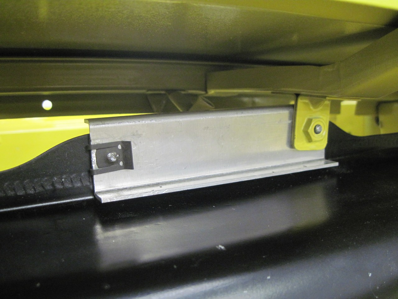
Then made a little right angle bracket, and powder coated the two pieces.
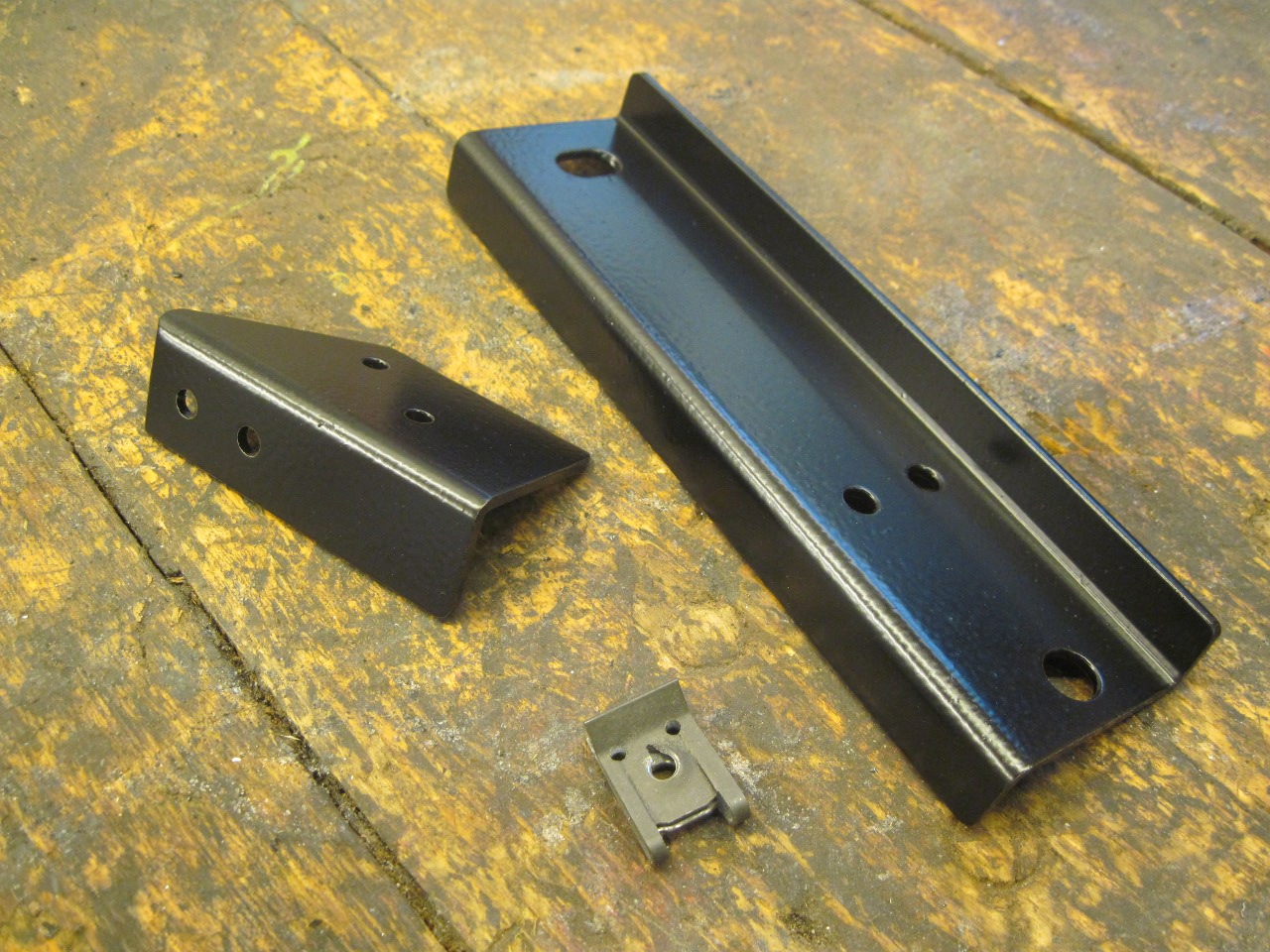
Putting everything together.
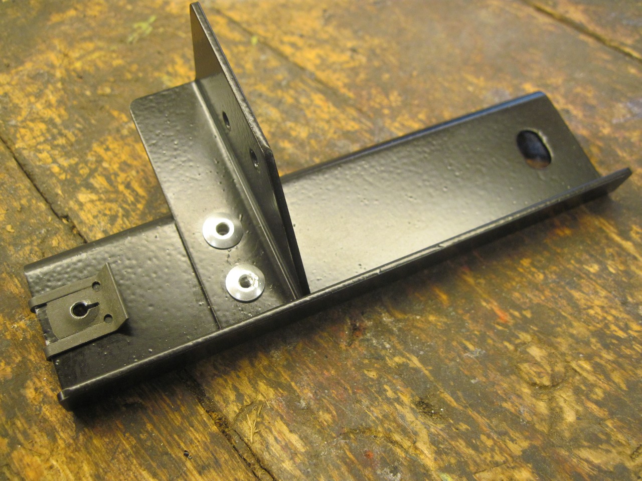
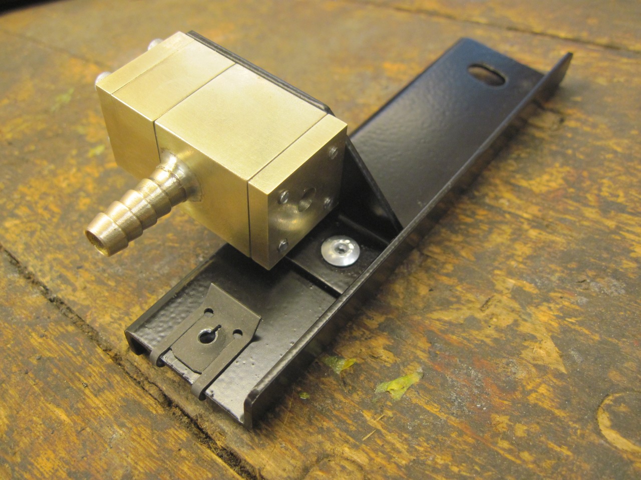
Since
the the valve assembly works entirely by gravity and has no springs, it
should be very nearly vertical to work best when the car is parked
in the garage.

This
is all very cool, but I did have one concern. I could see that
with a lot of sloshing in a nearly full tank, raw liquid gas could
easily go up the vent tube and into the valve, where it would probably
float the vacuum ball, and leak out on to the tank. What I needed
was a vapor separator. A light went on. I think this car
had one of those! I dug through some boxes, and sure enough, came
up with a crusty separator.
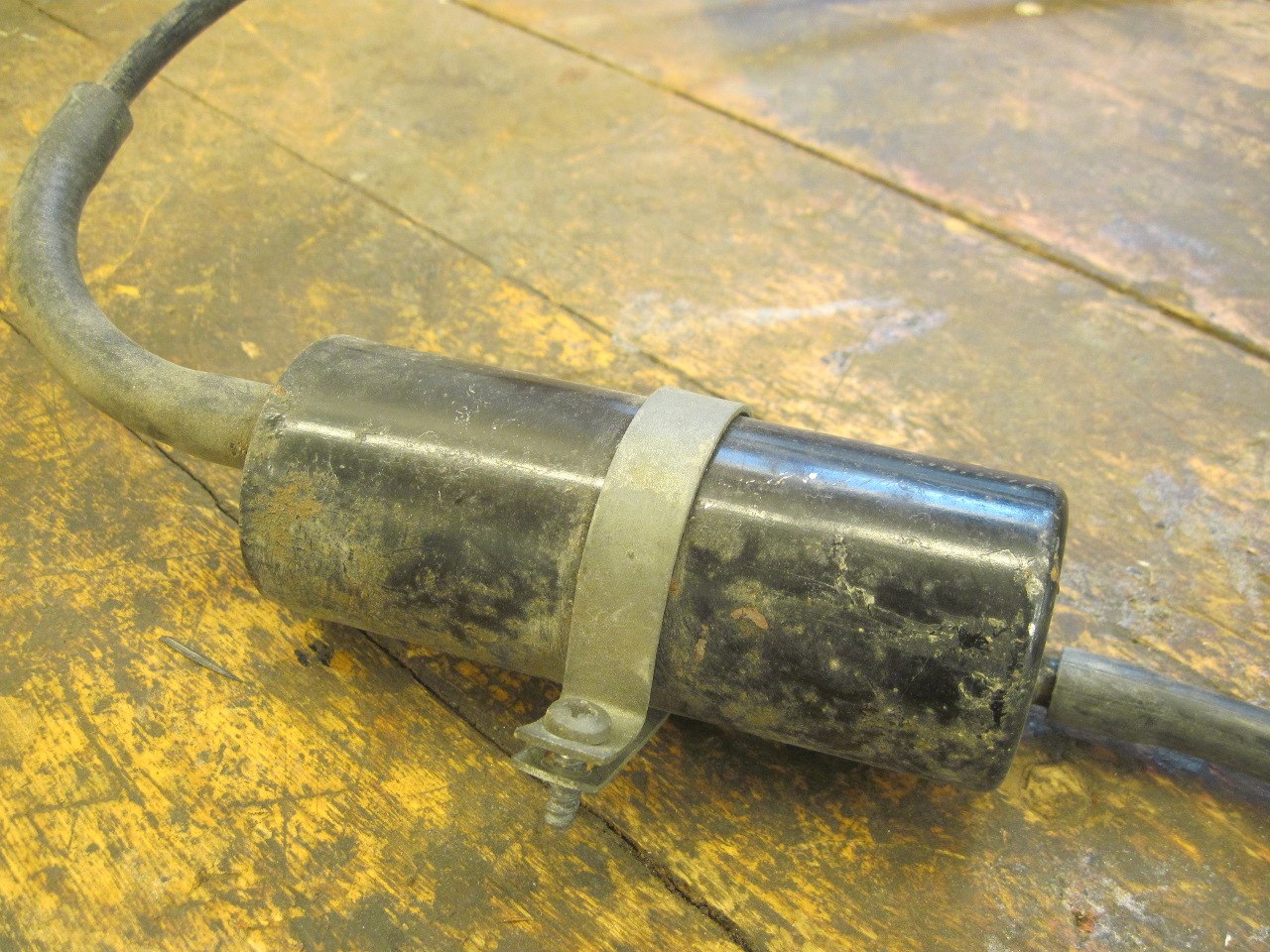
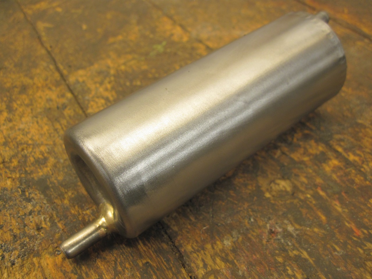
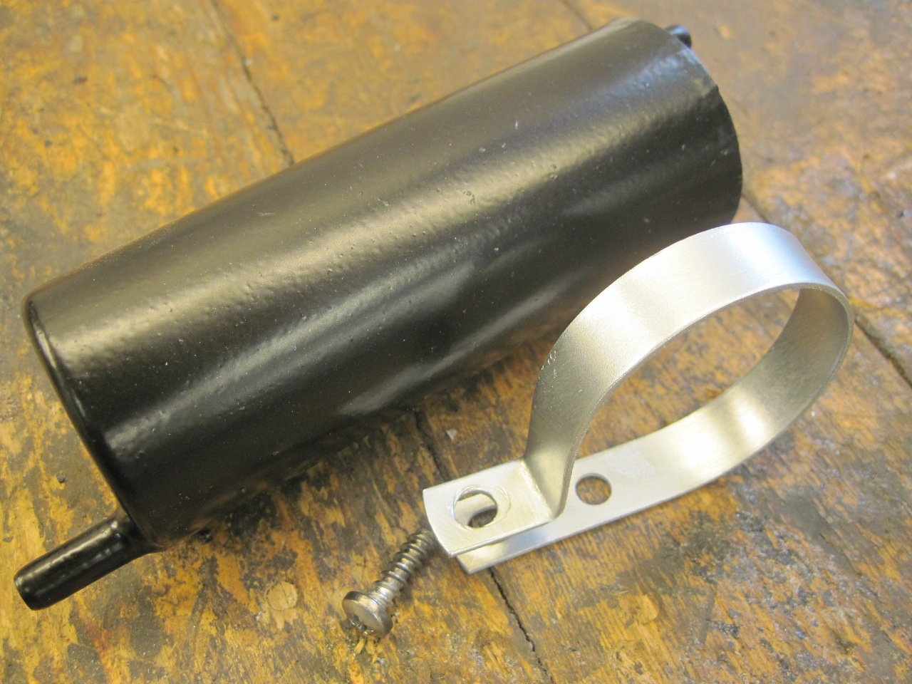
The
separator is just a small empty tank with shrewdly placed inlet and
outlet ports. In the later TR6, this tank was placed horizontally
above the fuel tank. A hose from the tank vent connected to a
port low on one end of the separator. The outlet was high on the
opposite end. Fuel splashed out of the tank would enter the
separator, and then simply drain back into the fuel tank by
gravity. Since the outlet was higher than the inlet, the entire
separator would have to fill up before any raw fuel would come out the
outlet. I've seen pictures of this separator installed upside
down.
So, cleaned up and powder coated the separator, and plated its bracket.

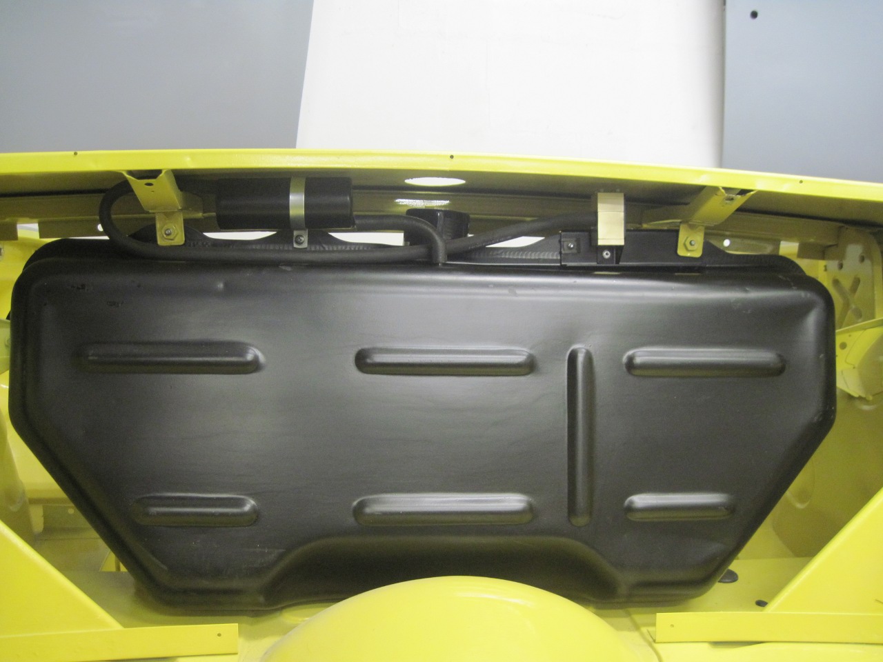
Mounted
the separator on the right side above the tank. The pressures and
vacuums are so low here, I may not even need hose clamps.
So
this job was really more about a science experiment than restoration.
It will be a while before I can test the valve in practice, and
it may not work at all. Well, at least it will be easy to rip out.
Comments to Ed at elhollin1@yahoo.com
To my other TR6 pages