To other TR6 pages.
December 6th, 2013
Water Pump
[Click pics for a larger view]
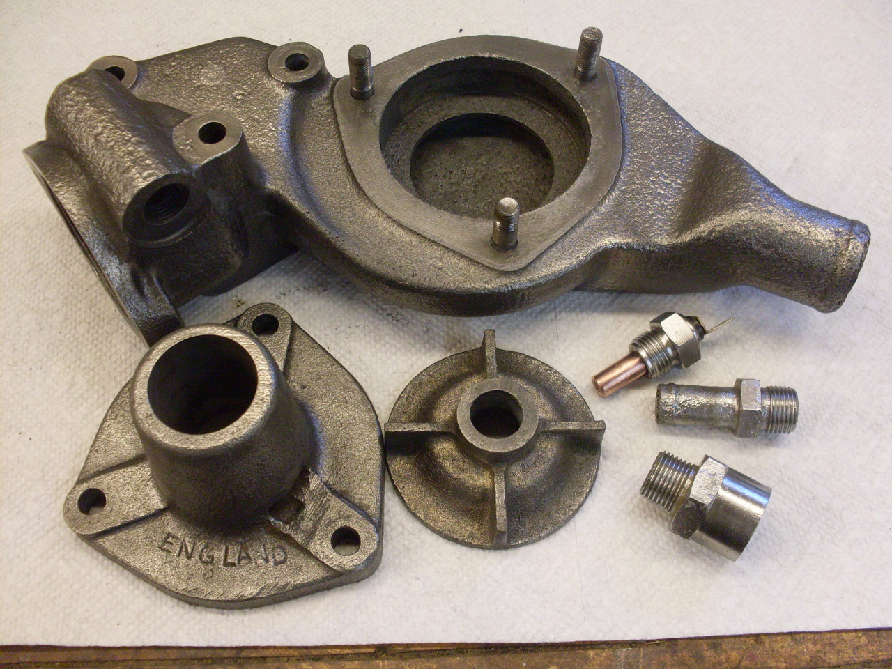
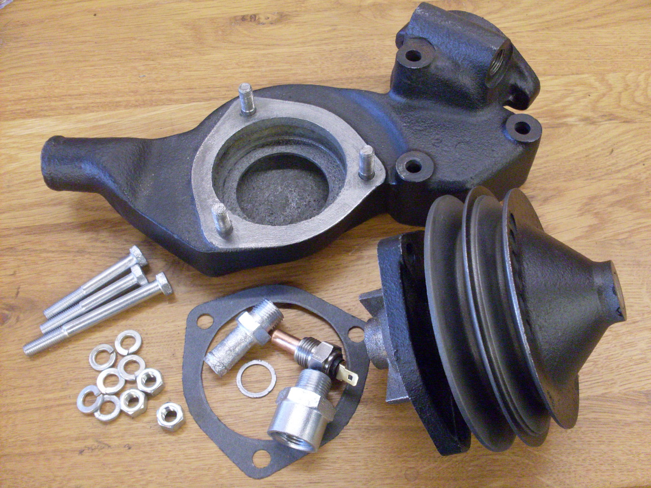
The
cooling system on the TR6 is a pretty ordinary pump assisted
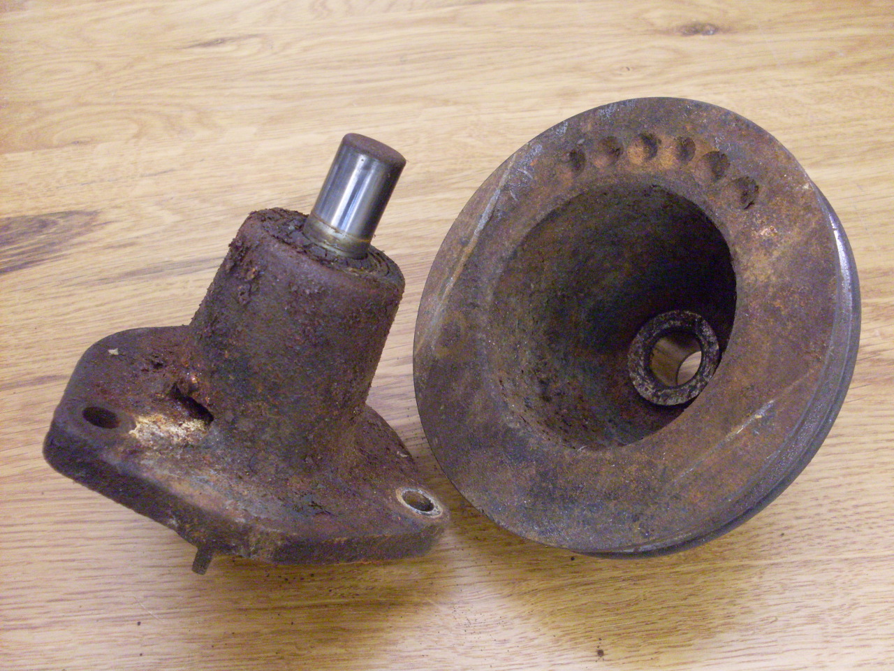
thermosiphon arrangement. The pump assembly is an odd-shaped
iron casting with various inlets and outlets that bolts to the
cylinder head.
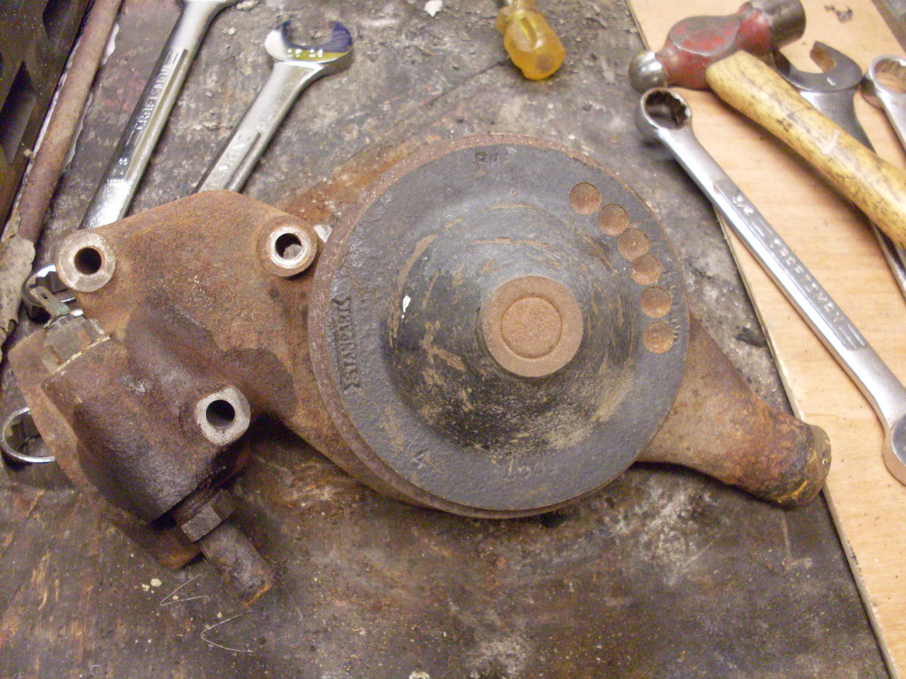
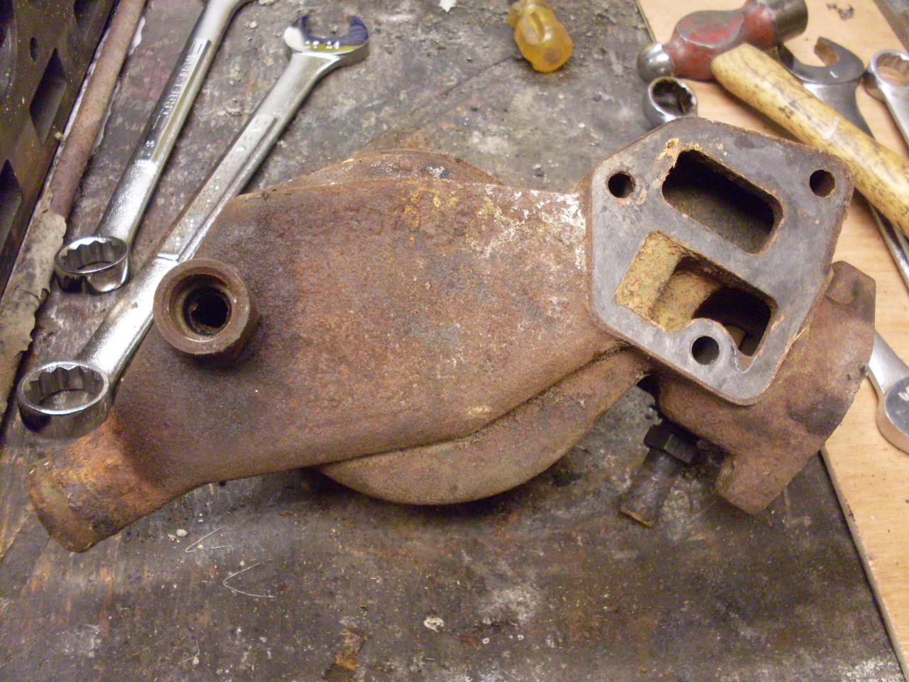
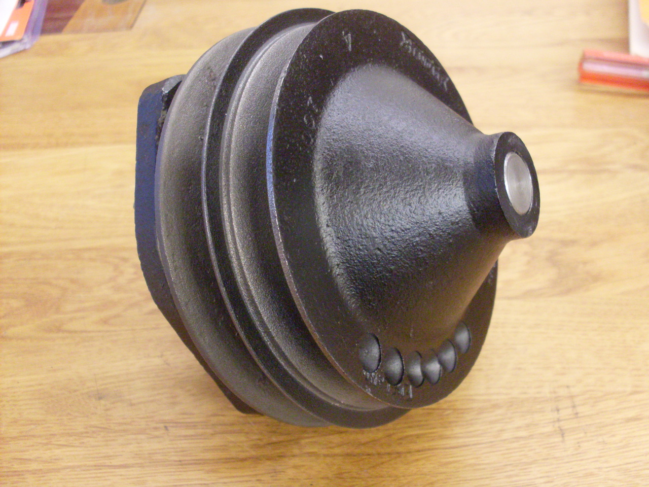
The pumping
is done by the impeller assembly, which is actually called the water
pump in most parts listings. This is the assembly that is
replaced when you "replace the water pump". The shell that it
bolts to is called the water pump housing.
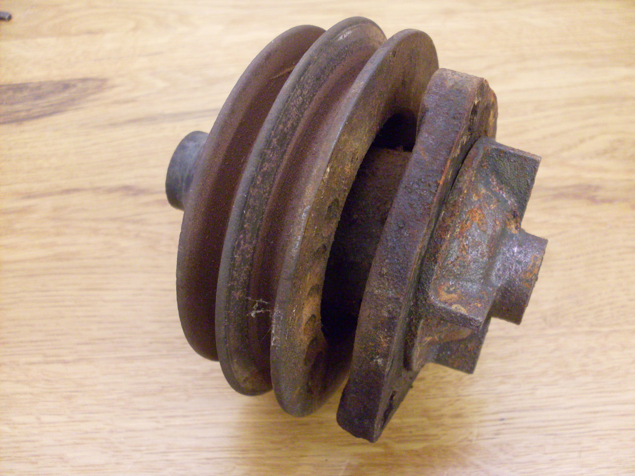
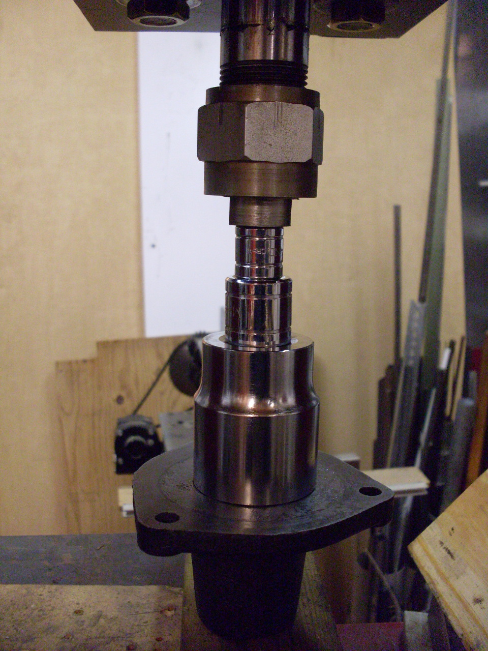
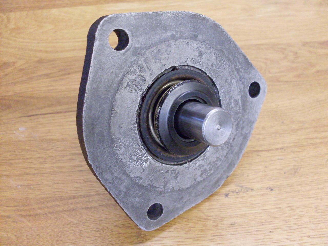
The
impeller assembly (water pump), while normally replaced as a unit, is
rebuildable, though parts are not found at most auto parts stores.
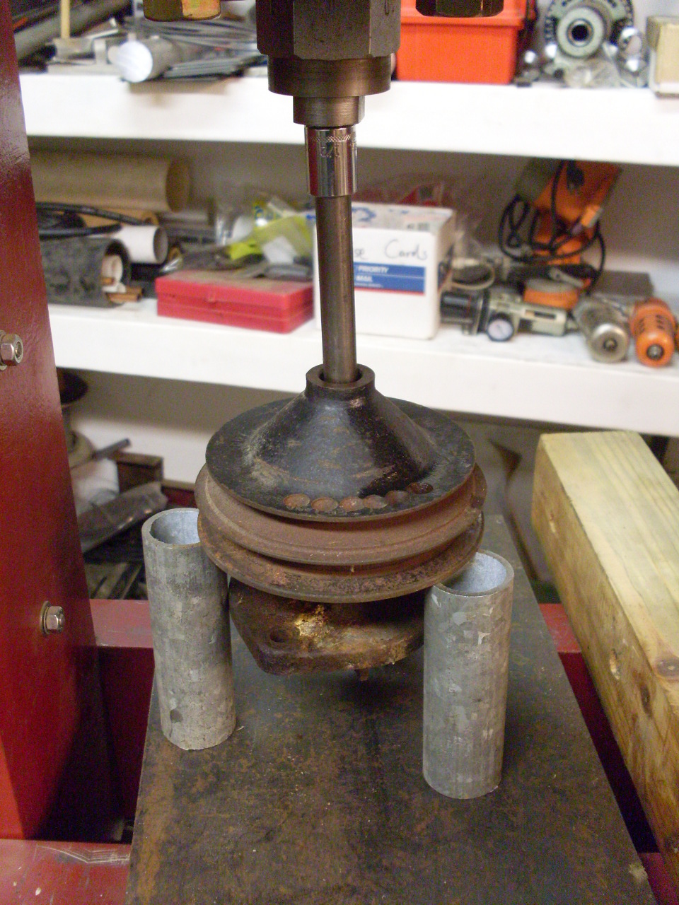
First step is to push off the pulley, then push the bearing out
of its housing, then push the impeller off the shaft. What's left
is the replaceable items: the bearing and the seal. It was
obvious from the rust patterns on the shaft and the bearing housing
that the seal had been leaking. The bearing, while still smooth
in turning did have a slight side-to-side play.

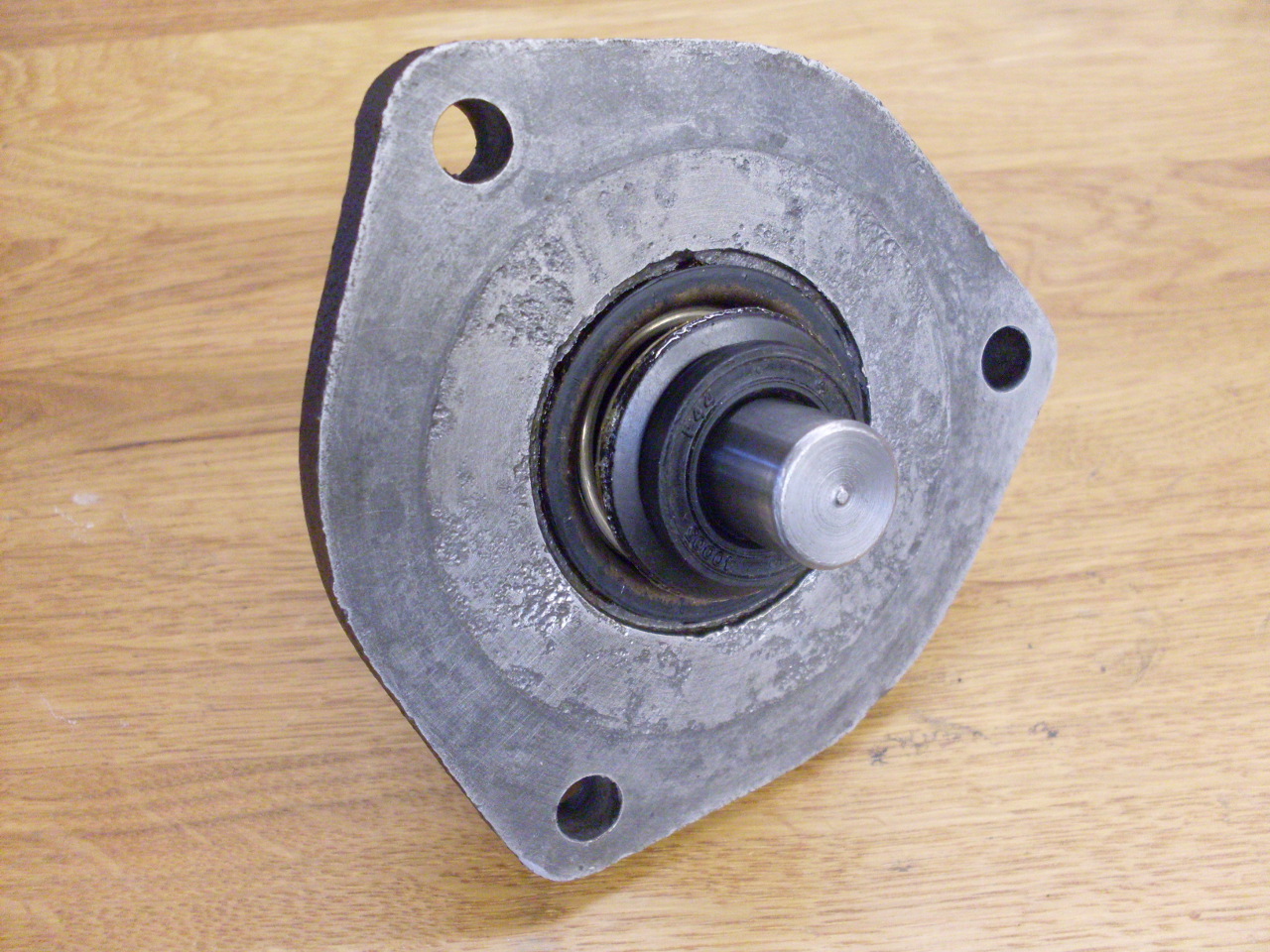
This
is what's called a water pump bearing. It is an outer race that
carries two ball cages, forming a "ball bearing" at each end.
There is no inner race--the balls run directly on the shaft.
It is a sealed unit with no external provision for lubrication.
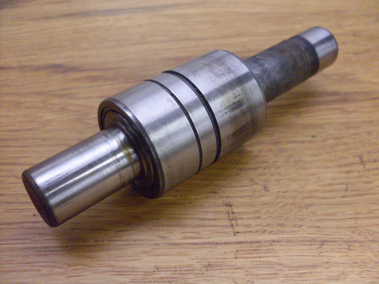
The
30 mm outer race diamater, 40 mm barrel length, and 16 mm shaft
diameter are apparently pretty common for these bearings, but the shaft
lengths are all over the map. Also, since these bearings are
typically used in automotive applications, many industrial suppliers
don't carry them (neither do most auto parts stores, for that matter).
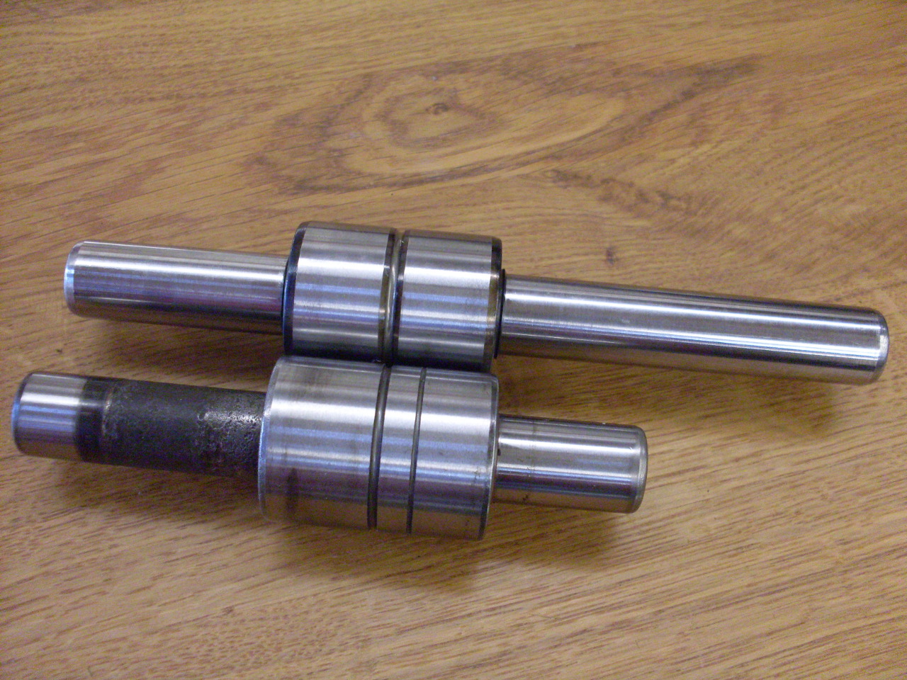
I did find a bearing supplier that had a unit with longer shafts,
but since the shafts are not hardened, at least on the parts that
protrude, it was easy to cut them.

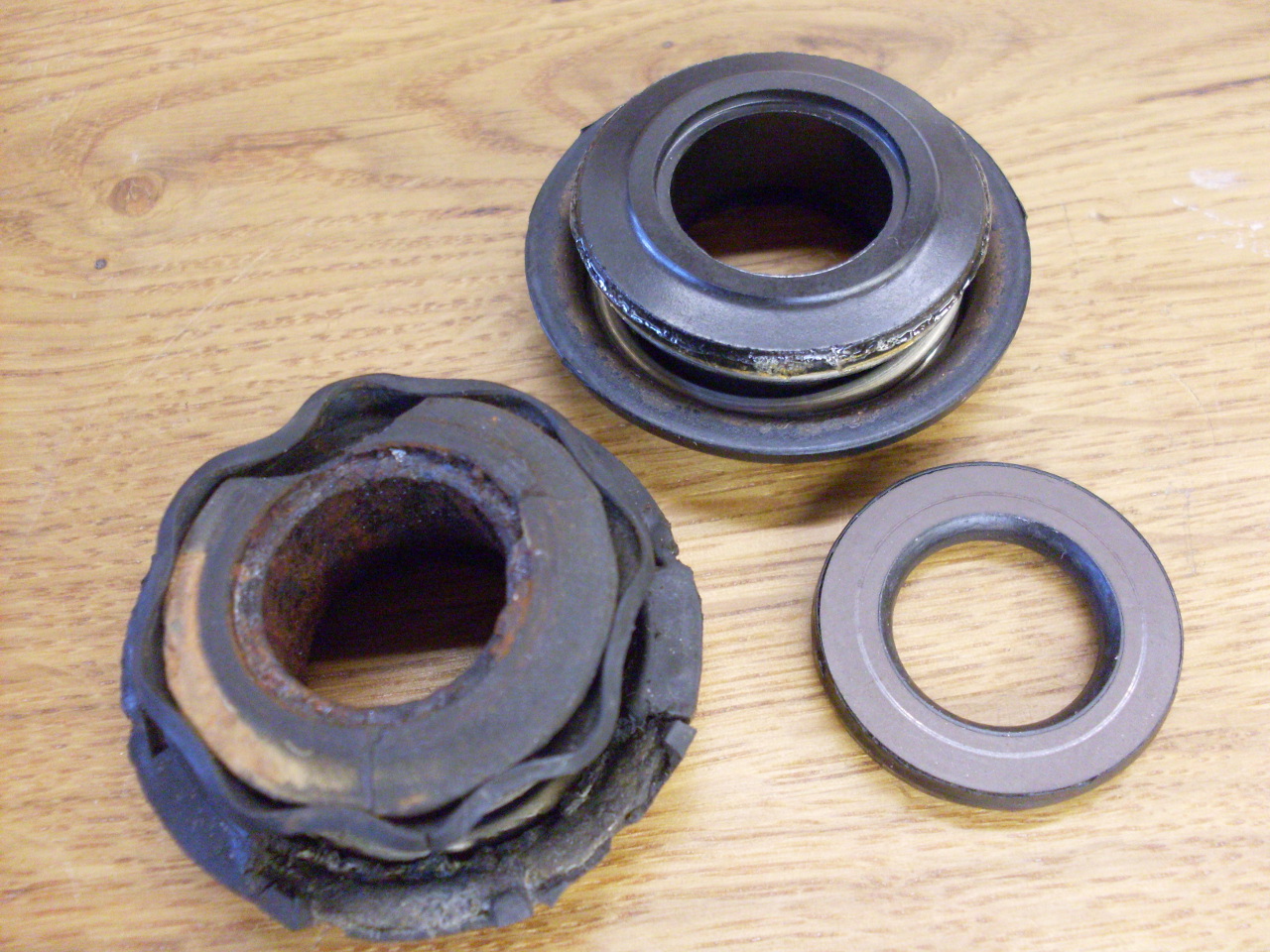
The
seal is a "mechanical seal" commonly used on wet pump shafts.
There are two hard graphite or ceramic discs--one stationary, and
the other spinning with the shaft--that form the primary seal.
The discs are in contact face to face under spring pressure.
There is a huge variety of these, and finding a replacement from
industrial sources was just too confusing. I ended up
finding a british-made NOS unit from an antique car parts outfit.
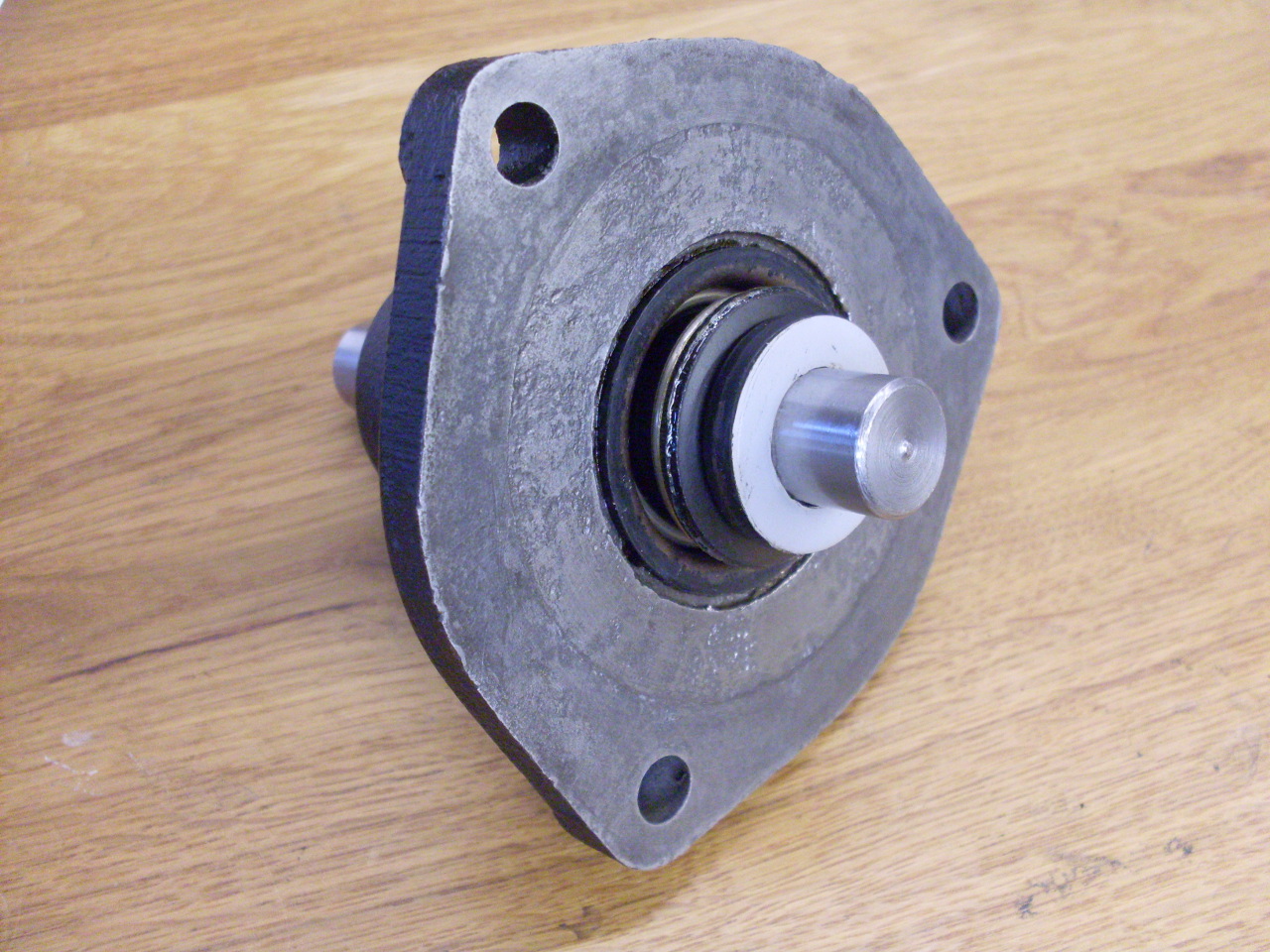
I cleaned up all the castings, and started to reassemble everything.
First, I pressed the seal into the housing using a large socket, then the bearing is pressed in.
Then
the rotating part of the seal in pushed onto the shaft. The
little white plastic washer was then placed on the shaft to give a
little (0.040") extra pre-load to the seal spring. I had done a
little arithmetic on where the impeller would end up on the shaft, and
found that the seal spring wouldn't be compressed very much. The
shim puts the spring about in the middle of it's range of travel.
The shim is necessary because of the close clearance I used
between the impeller and the housing. Since pumps and housings
are not matched sets, pumps have to have their impellers set to work
with any housing, and so a generous tolerance has to be included.
This results in the impeller being set farther back on the shaft
(towards the bearing), giving more preload to the seal spring, but
also more impeller clearance.
Then,
before the impeller is pressed on the shaft, I had to step back and
consider how I would know when it was in the right place. Even
though my numbers told me where I thought the right place was, I wanted
a little more practical method. For these pumps to work
efficiently, the clearances between rotating and stationary parts needs
to be kept to a minimum. The impeller blades need to run very
close to the housing face without fouling it. Here is the process
I used: First, I cut a little off the thickest blades so they
were all the same height and the tops of the blades were square to the
shaft. Then I pressed the impeller onto the shaft just a little
at a time until it was just very lightly dragging on the housing
without a gasket installed between the pump and the housing.
Since I had neglected to buy a gasket, I measured the old one and
it appeared to be about 0.015 thick, so I made a gasket from
0.015 gasket material. With the gasket installed and the pump
tightened down, the impeller doesn't drag, and the impeller clearance is about the gasket thickness--0.015".
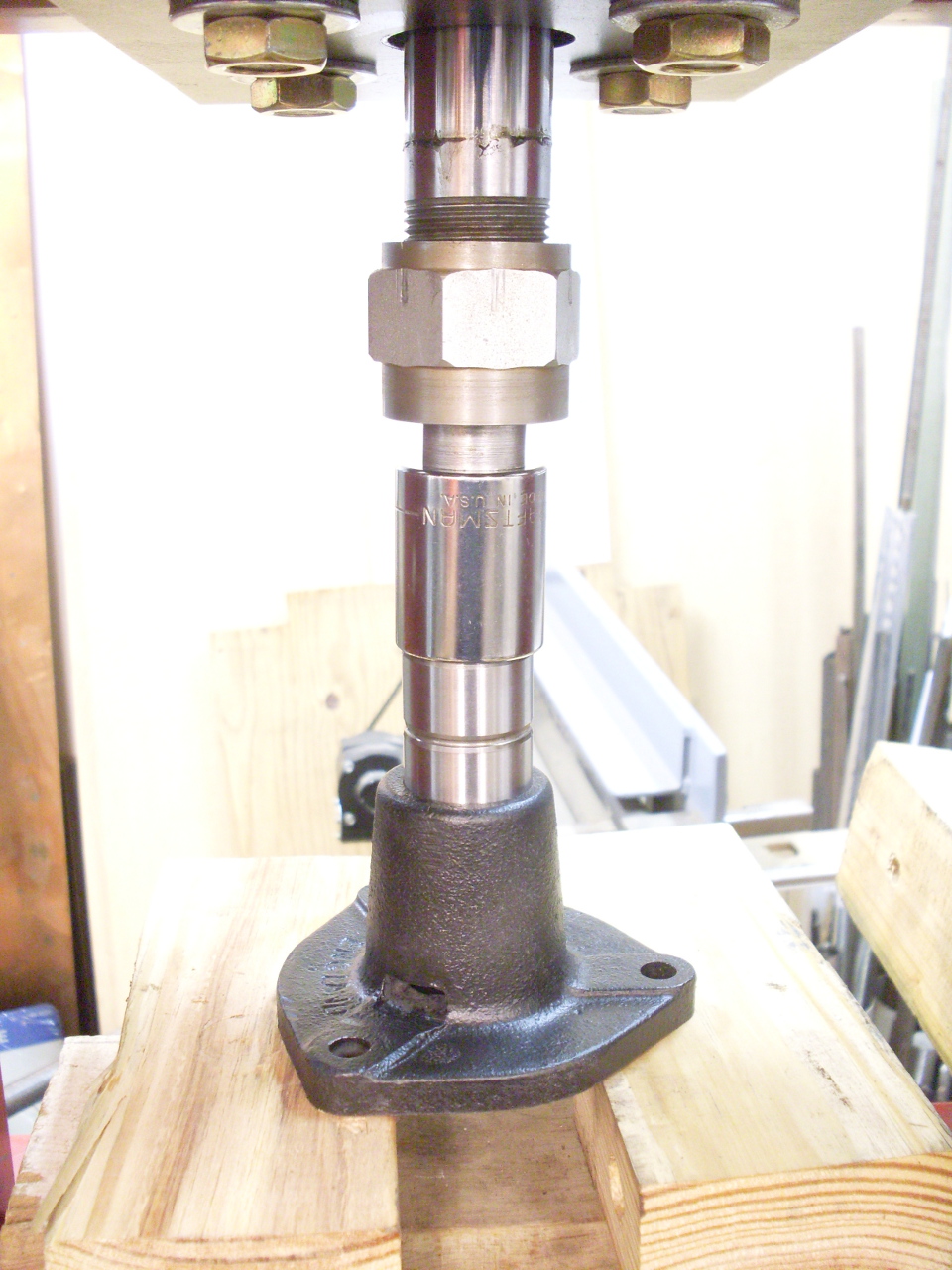
With all that done,
all that remained was to push the drive pulley onto the shaft, and here
is where one of those strange things happened that probably will always
remain a mystery. The pulley bore was too big! I mean way
too big. The pulley would fall on or off the shaft by
gravity. It couldn't be the shaft--it measured the same as the
old one to within less than a thousandth of an inch, and besides, the
impeller pressed on normally. I scratched my head about this for
a while, and finally gave up trying to explain it and concentrated on
what to do. I looked for pulleys online, but there were
apparently many different pulleys used for thesde pumps, even on the
same model car. And they weren't cheap!
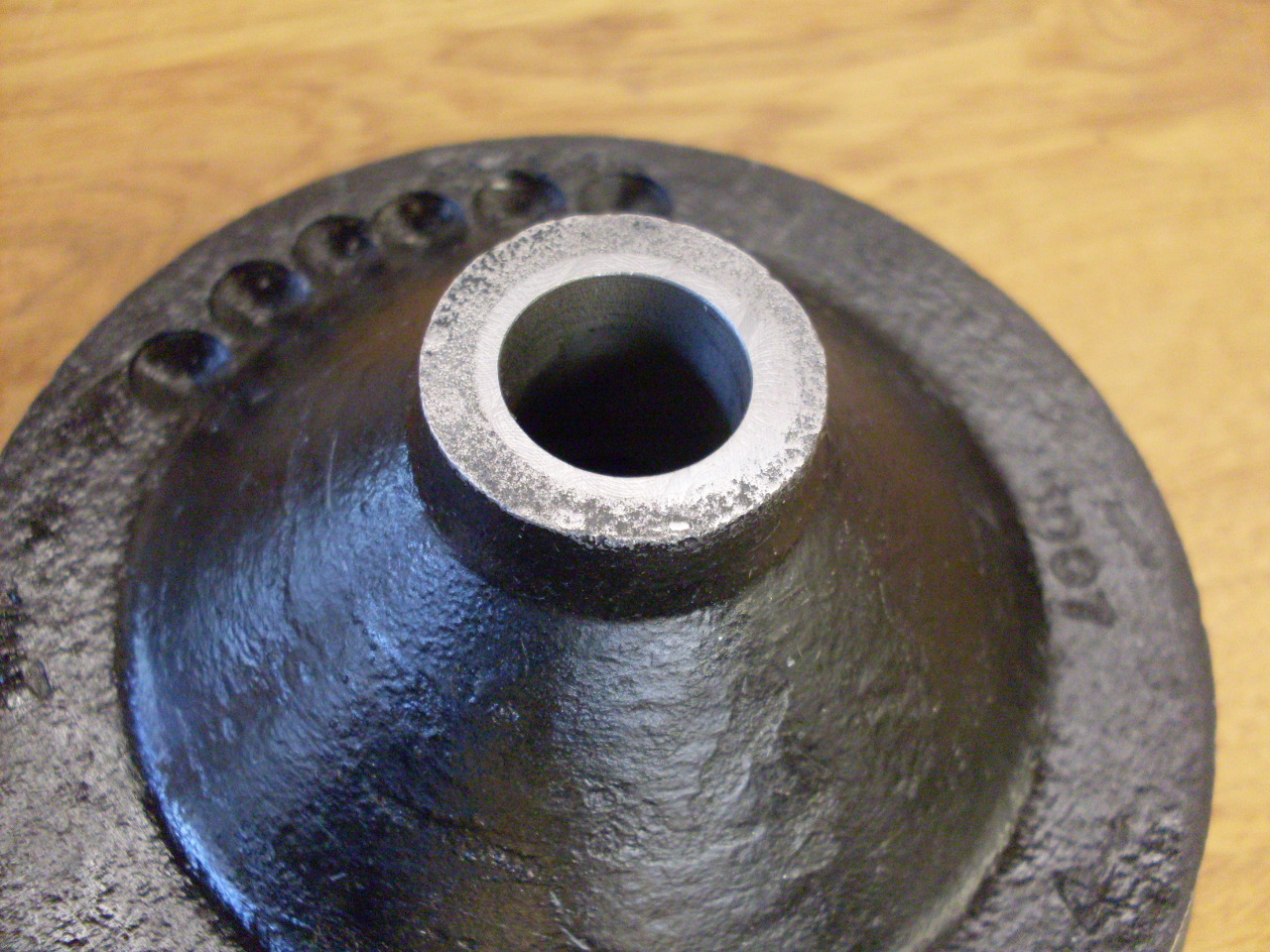
I finally decided
to fix my pulley by boring it out to 3/4", pressing in a slug, and
reboring the assembly for the 5/8" shaft. The first pic below is
the pulley reamed to 0.749" with a slug of .750 drill rod pressed in.
The green stuff barely visible at the joint is a Loctite bearing
mount compound. The second pic is the pulley reamed to 0.625"
(the shaft is 0.626"), and the slug trimmed flush. The pulley was then a nice press fit onto the shaft

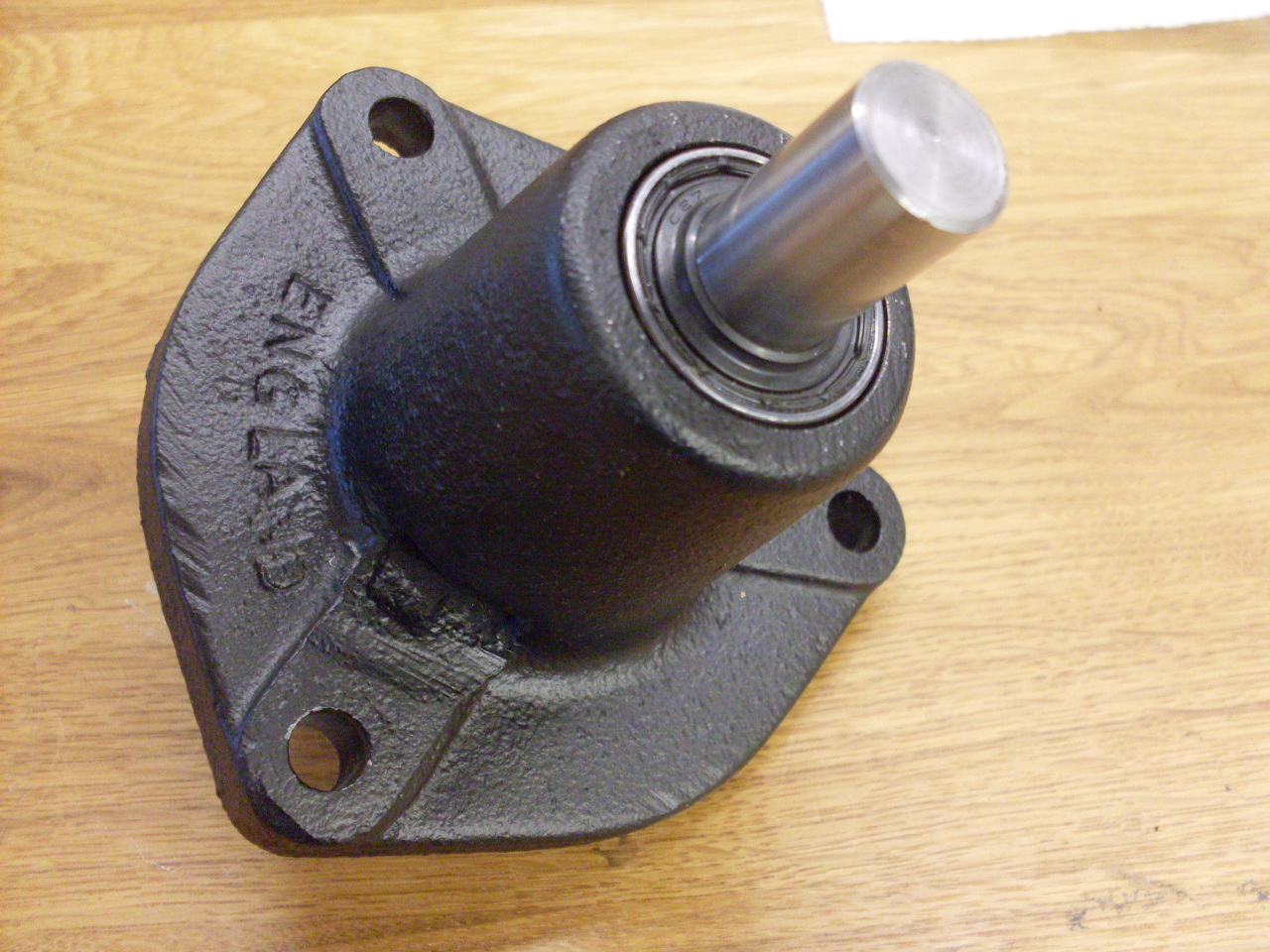
The pump was then ready to go back into the housing with replated hardware and fittings.
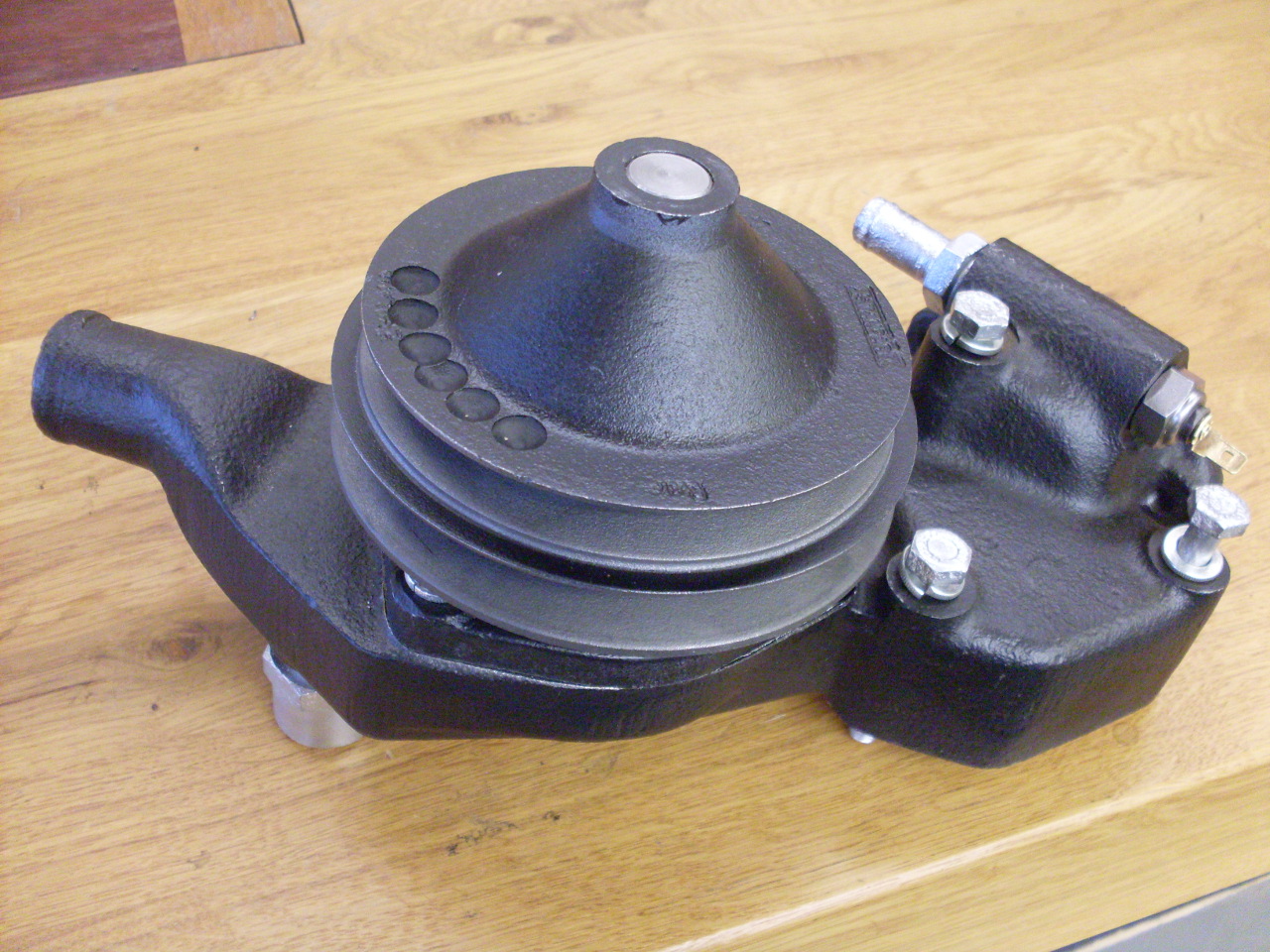
Total
cost of the rebuild was around $40 in parts. I have maybe 3-4
hours in it, but much of that was to repair the loose pulley bore.
To other TR6 pages.
Comments to: elhollin1@yahoo.com