To my other TR6 Pages
October 30, 2016
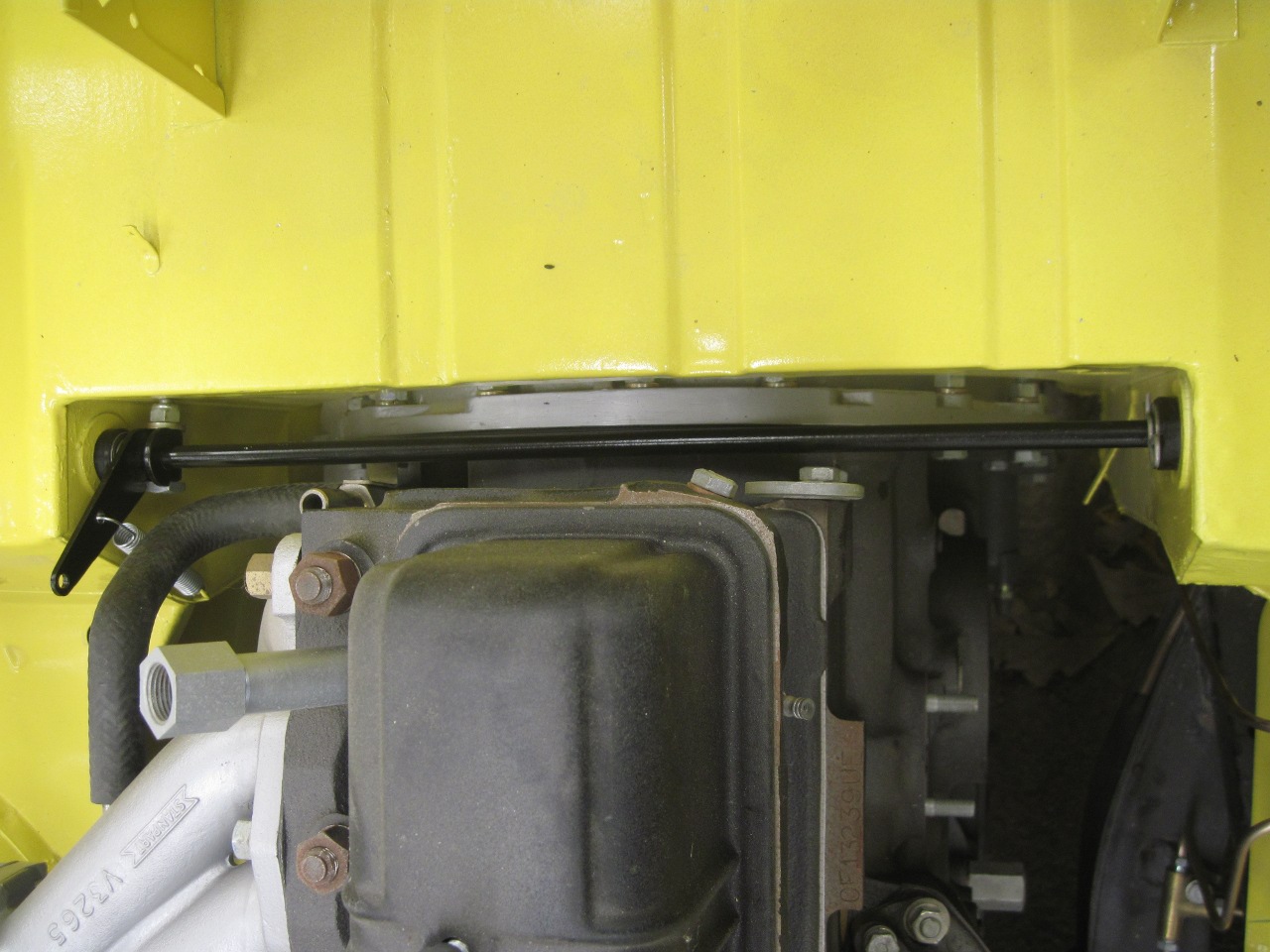
Accelerator Shaft
[Click the pics for a better view]
For
left hand drive (LHD) TR6 cars, which is the vast majority of them, the
accelerator pedal on the left side of the car has to operate the
carburettor throttle plates on the right side of the engine. This
is accomplished by a metal shaft running cross-wise directly behind the
engine. On the port end of the shaft is the accelerator pedal,
attached such that pushing the pedal rotates the shaft. The shaft
passes through the firewall in the driver's kickspace, across the
engine compartment where its starboard end is supported by a hole
into the passenger's footwell. Just before it leaves the engine
compartment, the shaft has a lever arm clamped to it. This is
where the corburettors' throttle linkage connects.
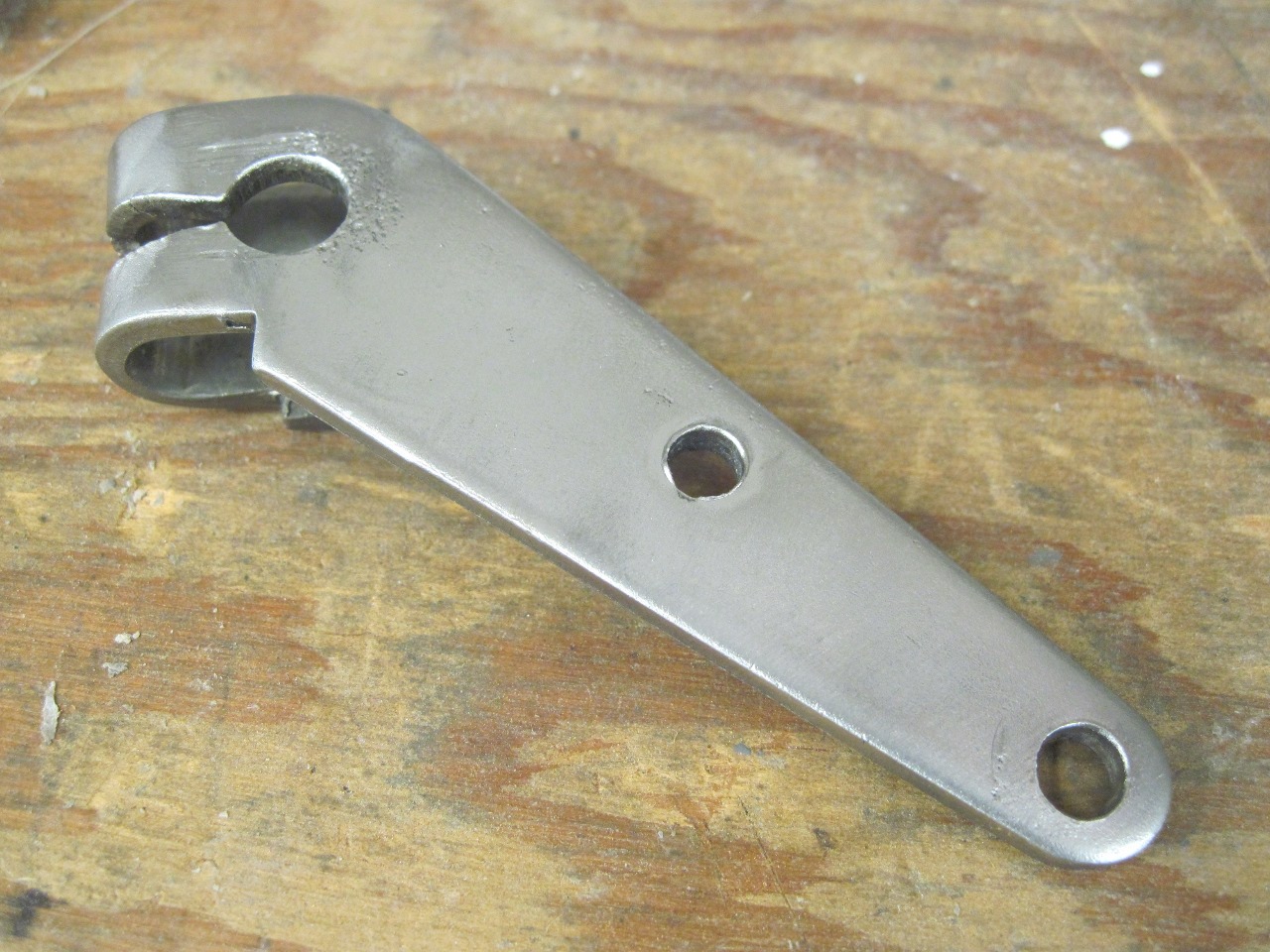
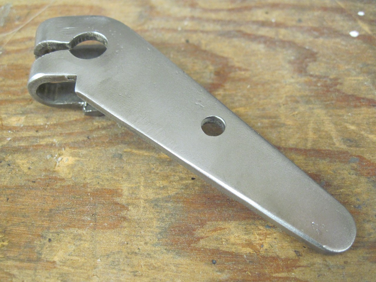
The shaft
and pedal were rusty and dirty, but in servicable condition. The lever
arm had an ovaled hole where the linkage attaches. The picture
doesn't show how bad the elongation was. The path from the
accelerator pedal to the carb throttles in a TR6 is a complex one with
an unreasonable number of joints and pivots, each contributing its
share of slop to the total, so to tighten the system up, every
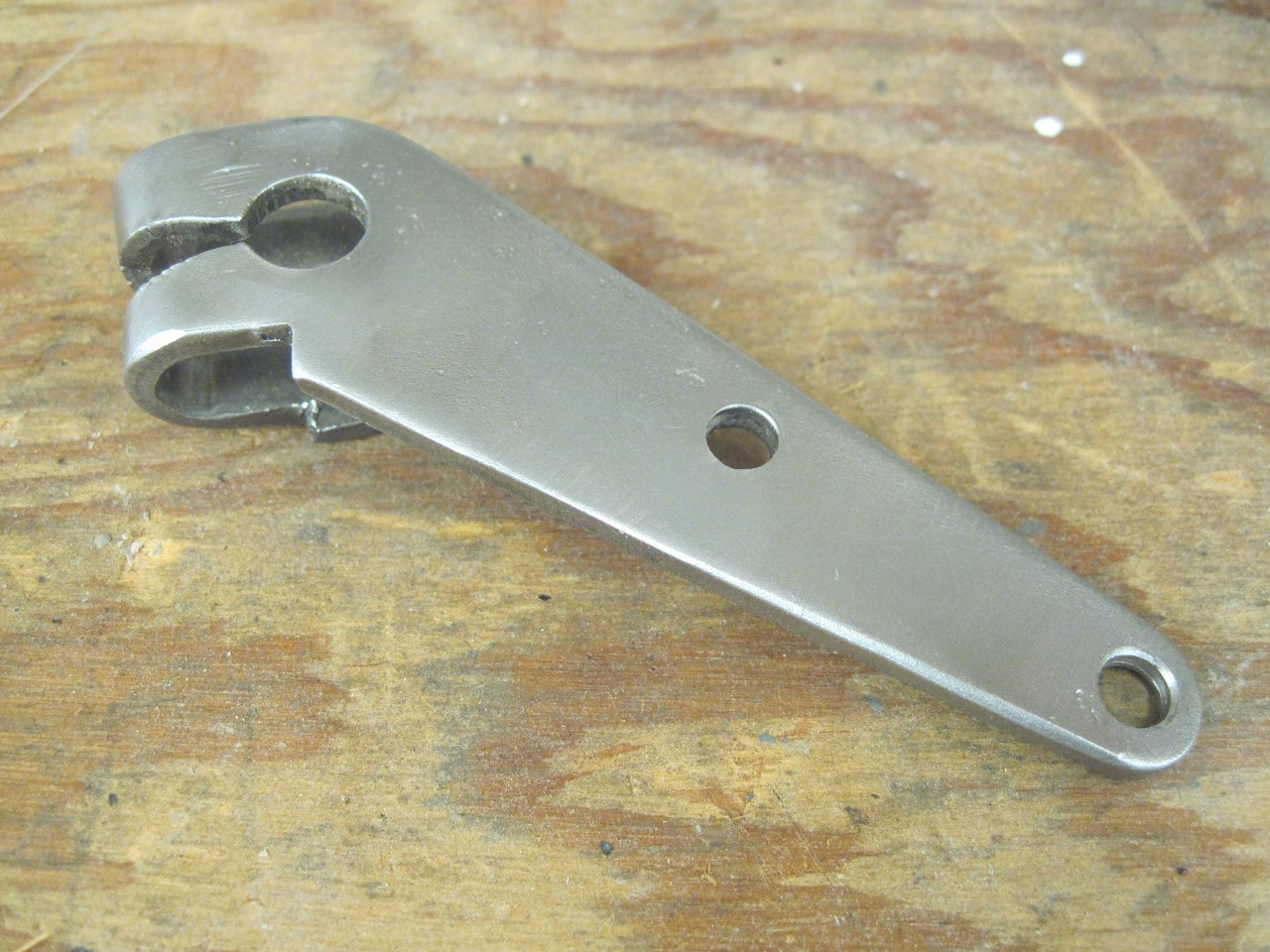
intersection has to be made as good as it can be. For the lever
arm, I welded up the hole and redrilled it.

The
other thing about these shafts is the bushings that it rides in.
They are reportedly hard rubber or plastic, prone to wear, and a
bear to replace. I wouldn't know what they look like, because
they were not present in this car--probably wore through and fell out
during the Reagan administration.
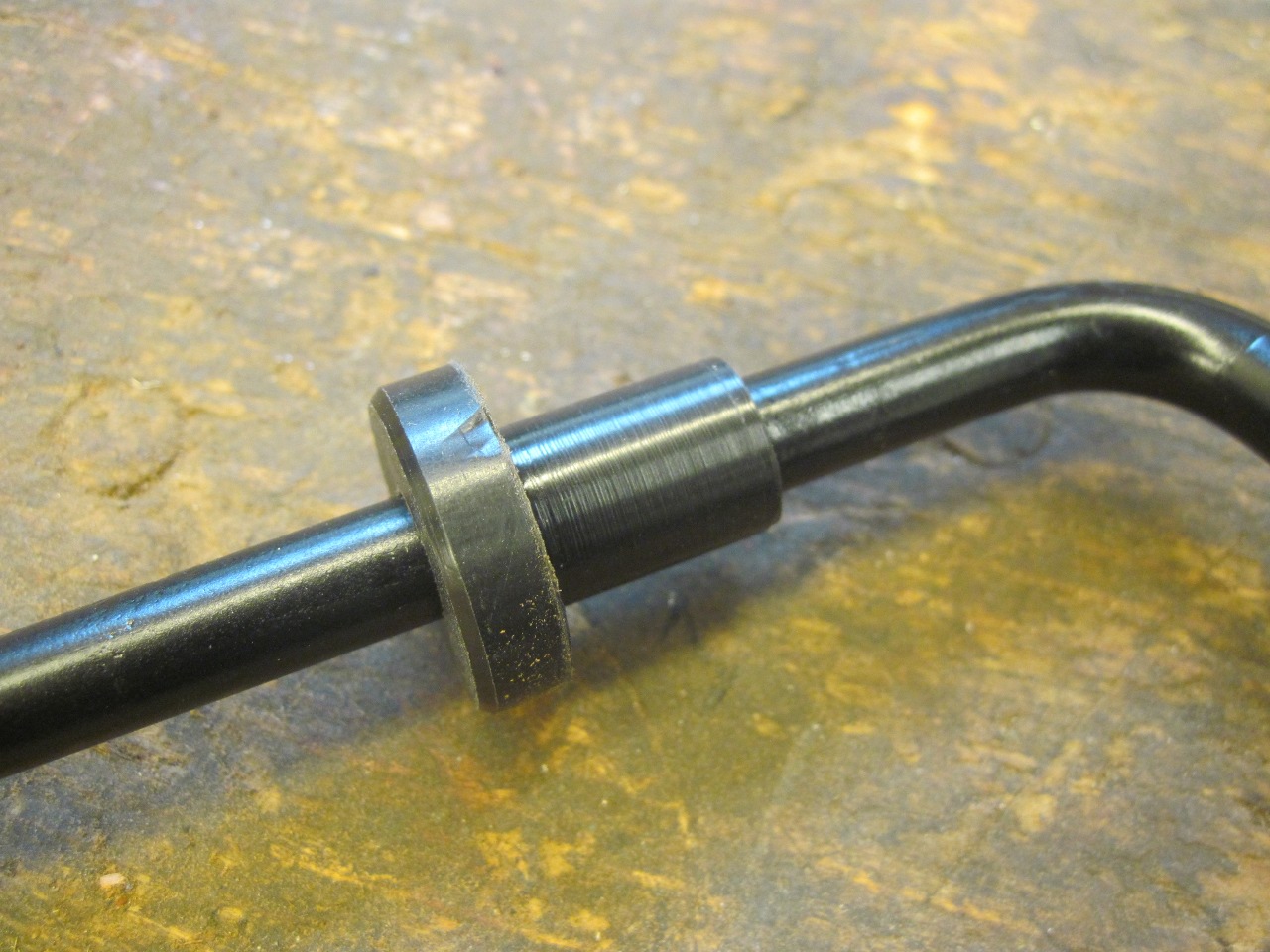
This is an area that begs for
improvement, and there are many good solutions. For this car, I
made two of these little bushings out of nylon. They are a
sliding fit on the shaft and a firm fit in the tub holes. Nylon
is a reasonable choice due to its natural lubricity.
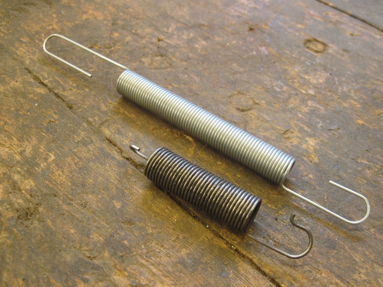
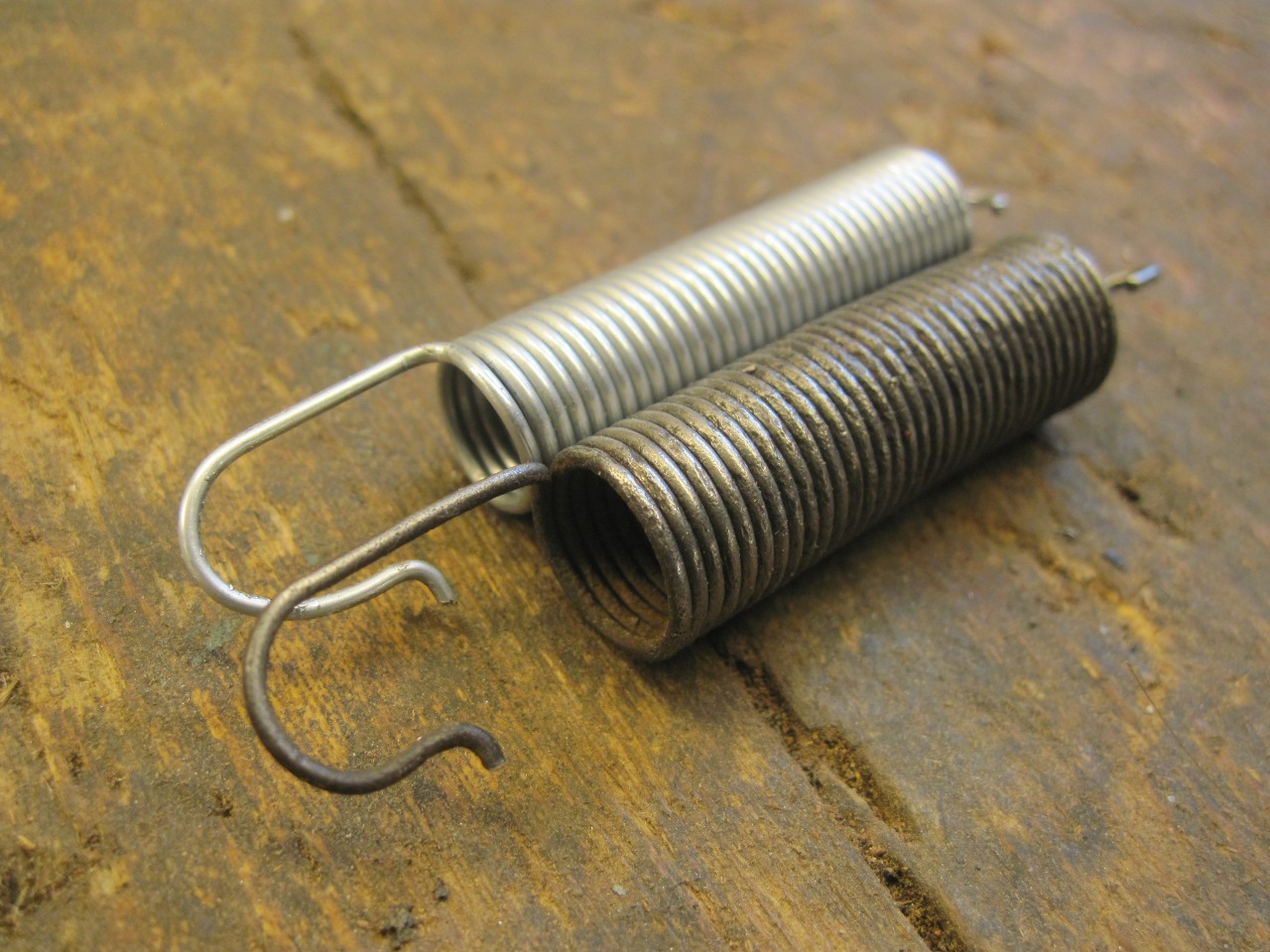
There
is also a spring that pulls the lever arm down, which rotates the pedal
up. The spring was pretty rusted, so I got a close-ish hardware
spring and modified to to be a close match.
So
here are all the parts that will go into the new and improved
accelerator shaft assembly. The shaft is painted, the lever
powder coated, and the clamp screw replated.

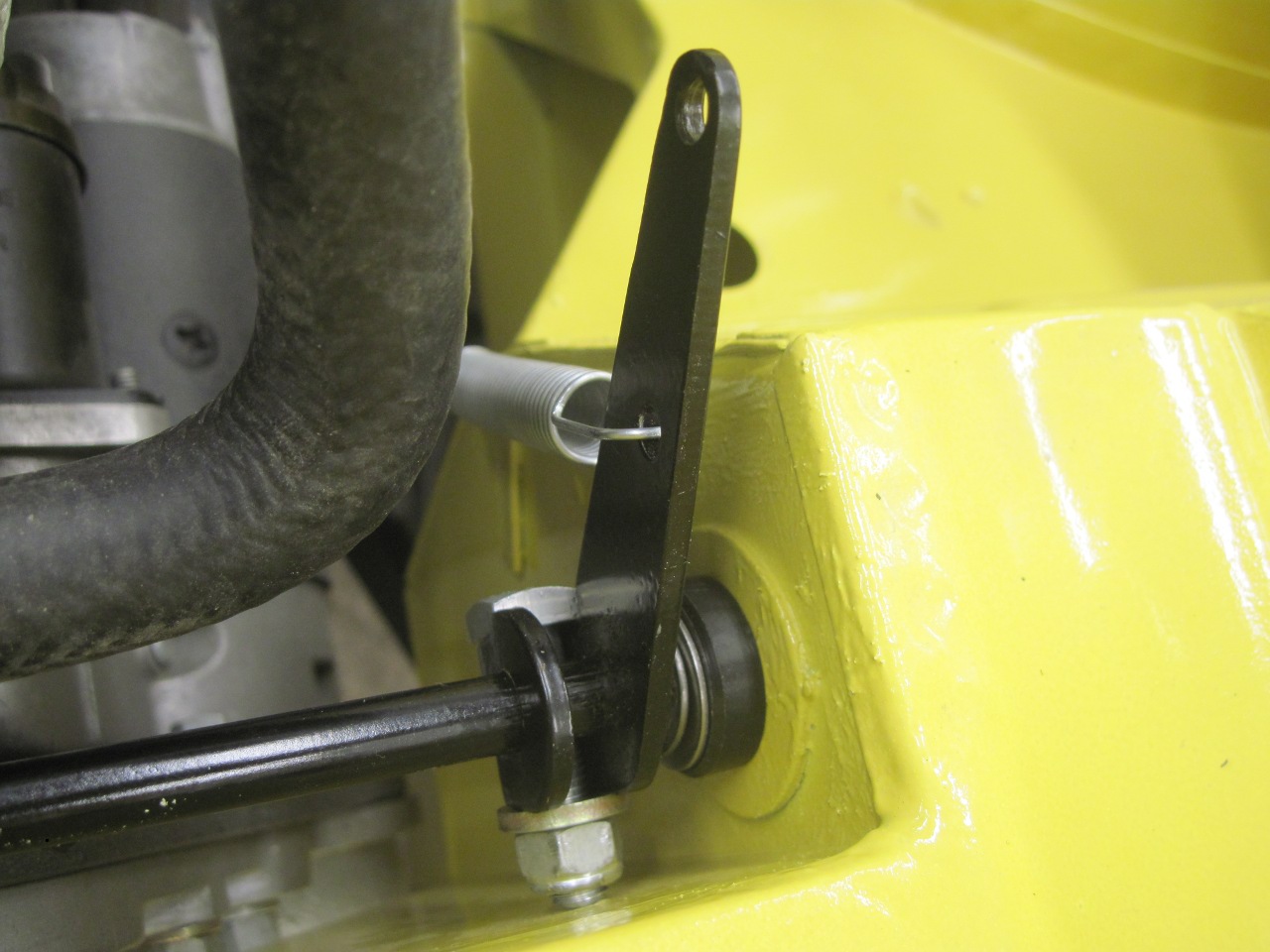
There
is a difference of opinion on which way the lever arm goes on the
shaft. Most, if not all of the catalogs show the long arm on the
outboard side, while Bently shows it the other way. I assume
Bently is right, but since my new bushing moved the lever arm towards
the center of the car a little, putting the arm to the outside put it
in better alignment with the body tab that the extension spring
connects to.
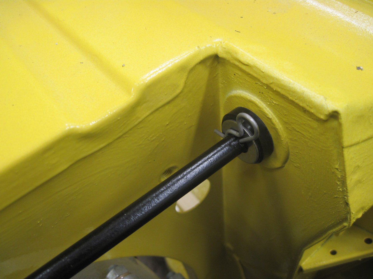
At
the other bushing, a keeper pin goes in a drilled hole. The lever
arm is positioned such that putting the pin in the hole slightly
compresses the Thackery spring washer on the shaft next to the arm.
This takes up any back and forth play in the shaft so it can't
rattle.
Accelerator action is now tight and smooth.
This was a fun little project. It took a few hours, but the cost was almost nothing.
Comments to Ed at: elhollin1@yahoo.com
To my other TR6 Pages