To other TR6 pages
December 5, 2013
Alternator
[Click the pics for a larger view]
My
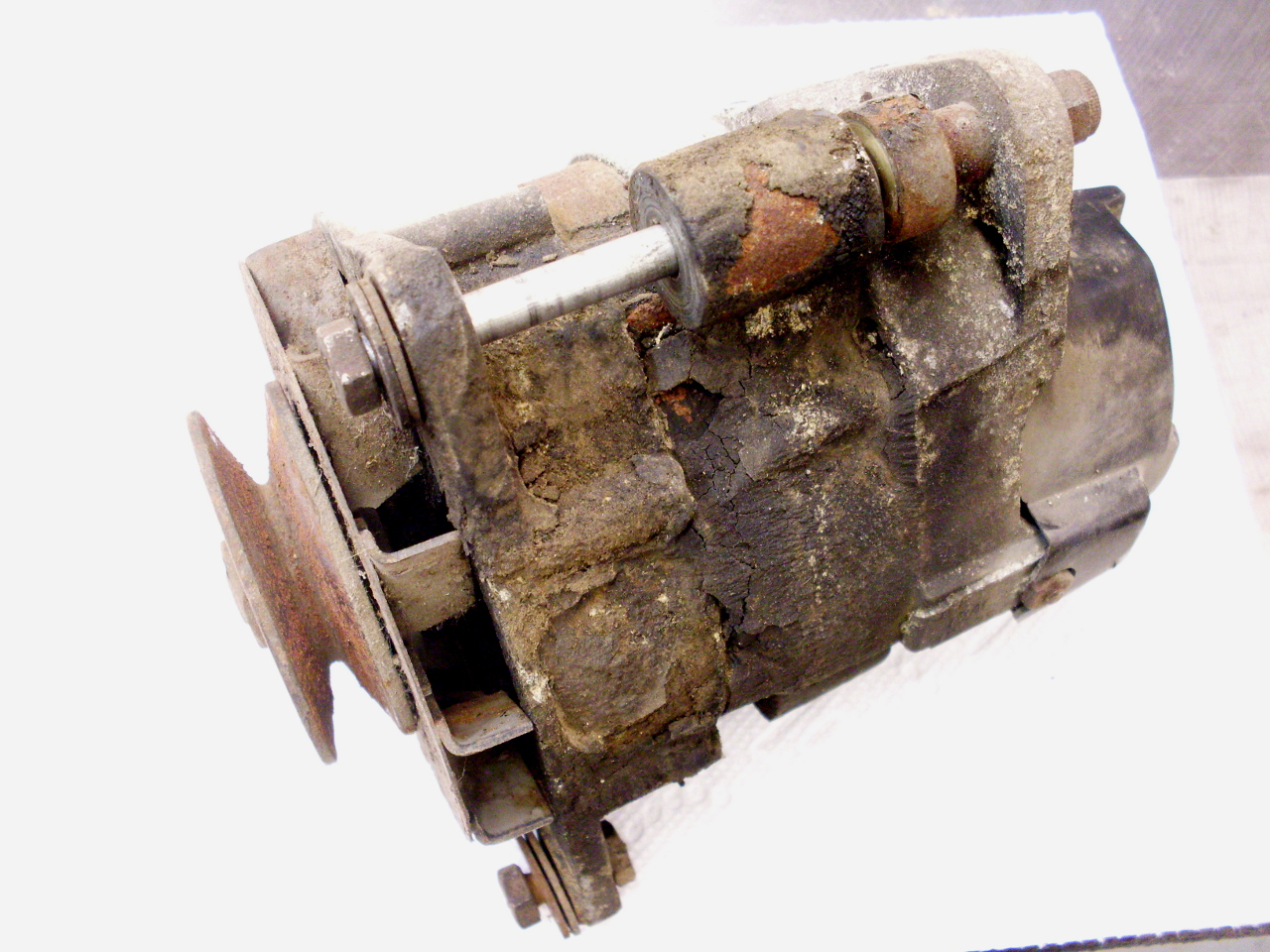
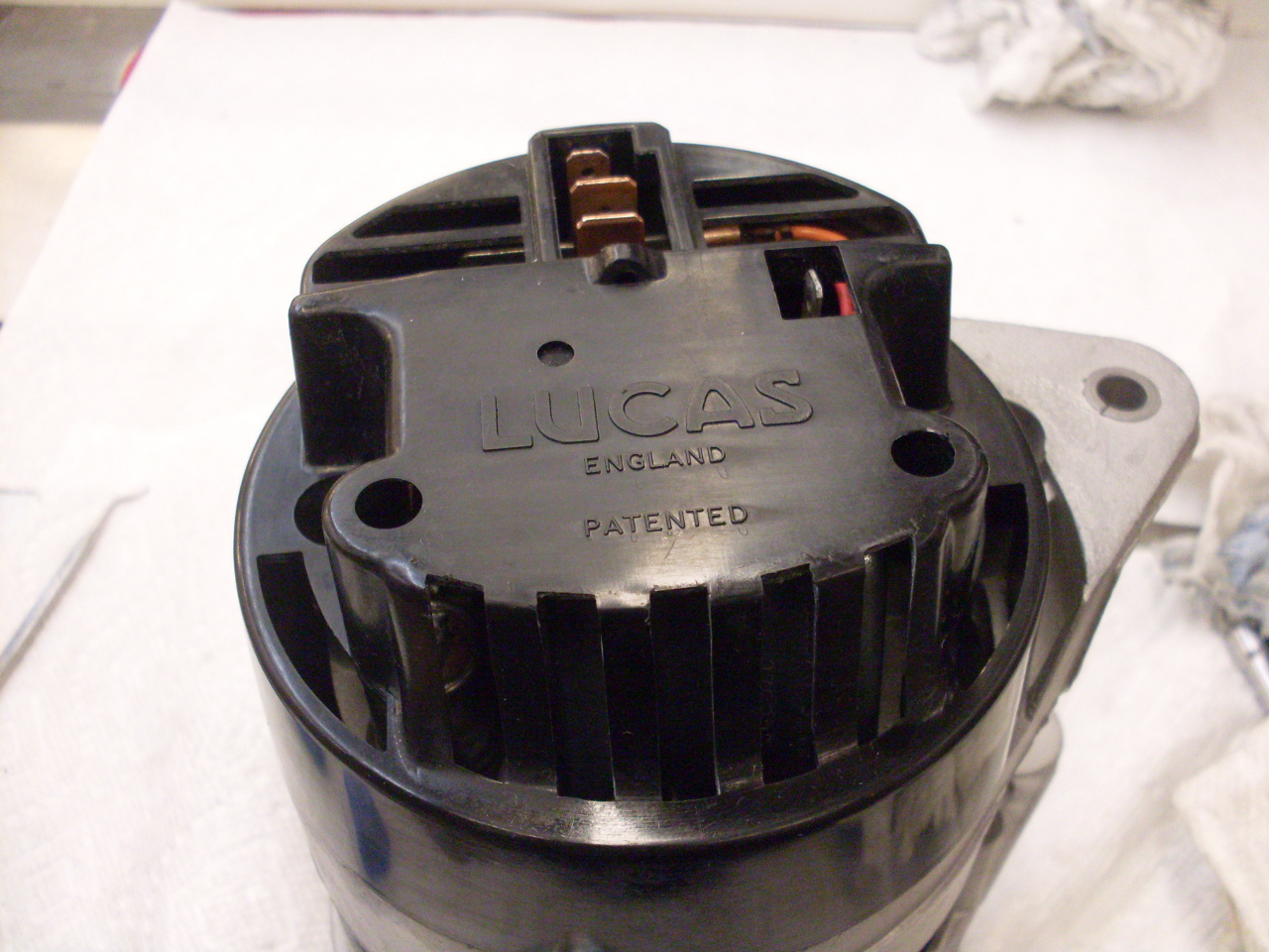
TR6 was fitted with a Lucas 18ACR Alternator. It is a three phase
unit with a rating of 45 amps. Earlier cars came with similar
units but with lower output capacity. The alternator was
appropriately dirty and crusted with dirt and grime, but appeared sound
except for stiff and gritty feeling bearings. There are rebuild
kits for these, but as far as I can tell, they aren't available in the
US, where the usual approach is to replace it as a unit. Rebuild
is a little more involved than some other subassemblies on the car, but
not beyond what a capable DIYer can do.
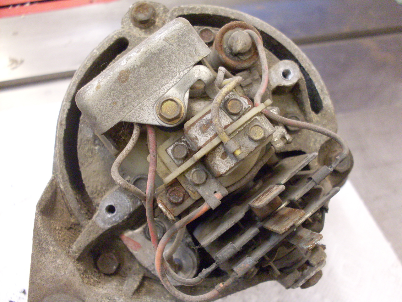
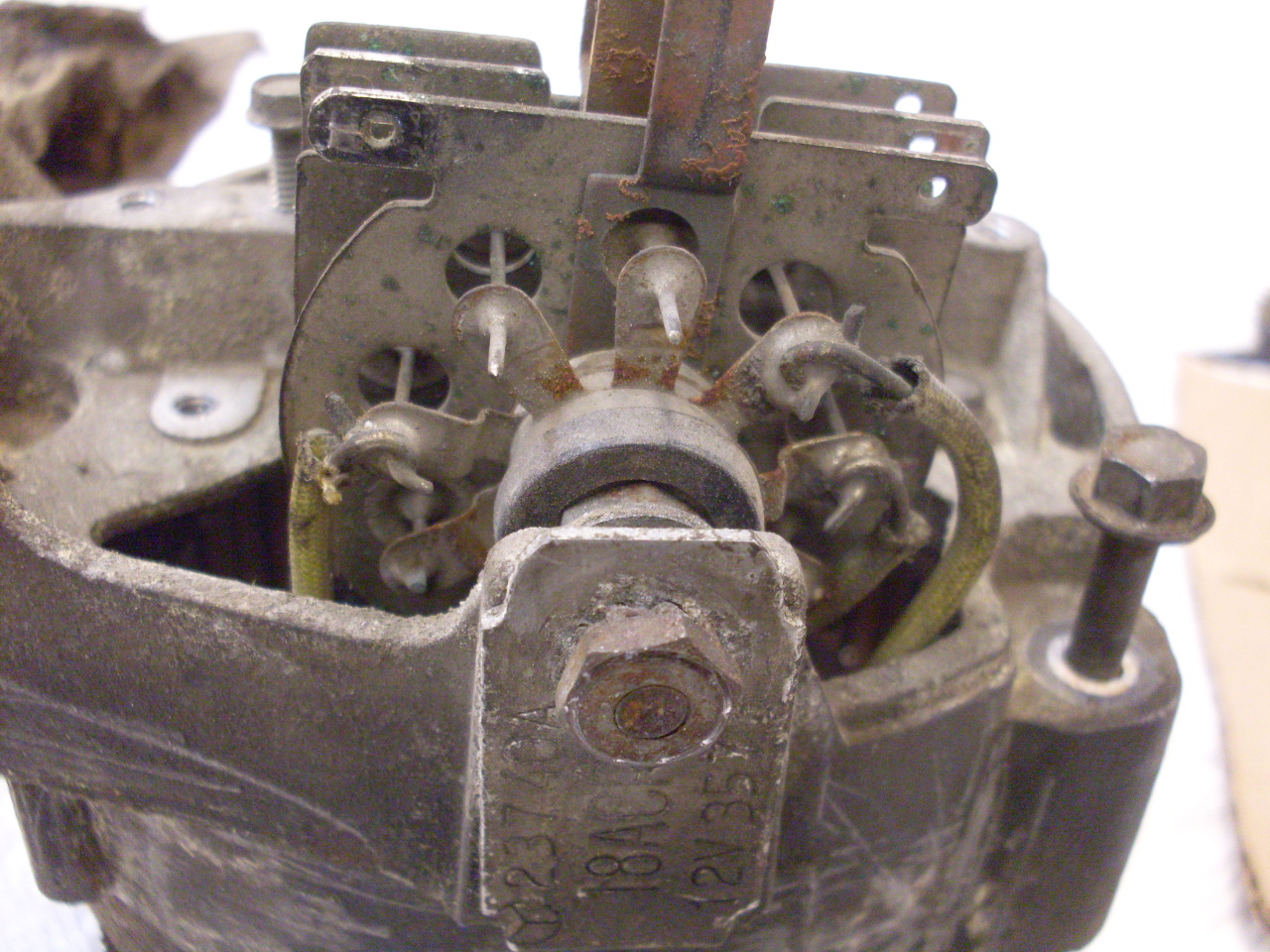
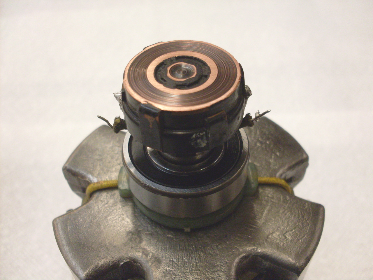
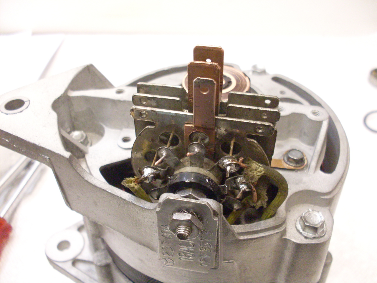
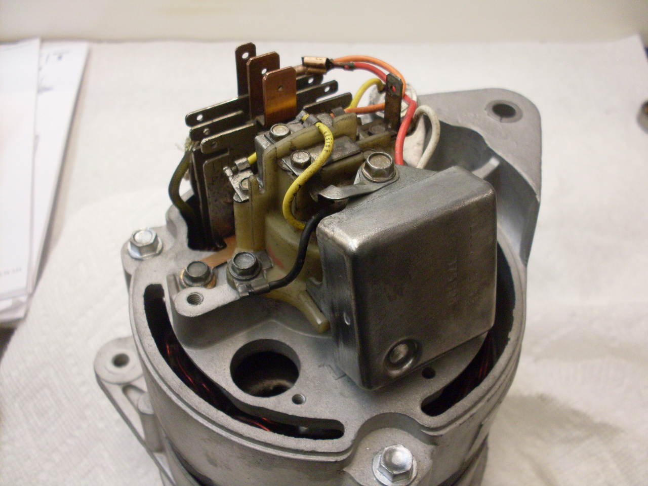
Taking
off the plastic rear shroud reveals the electrics and a tangle of wires
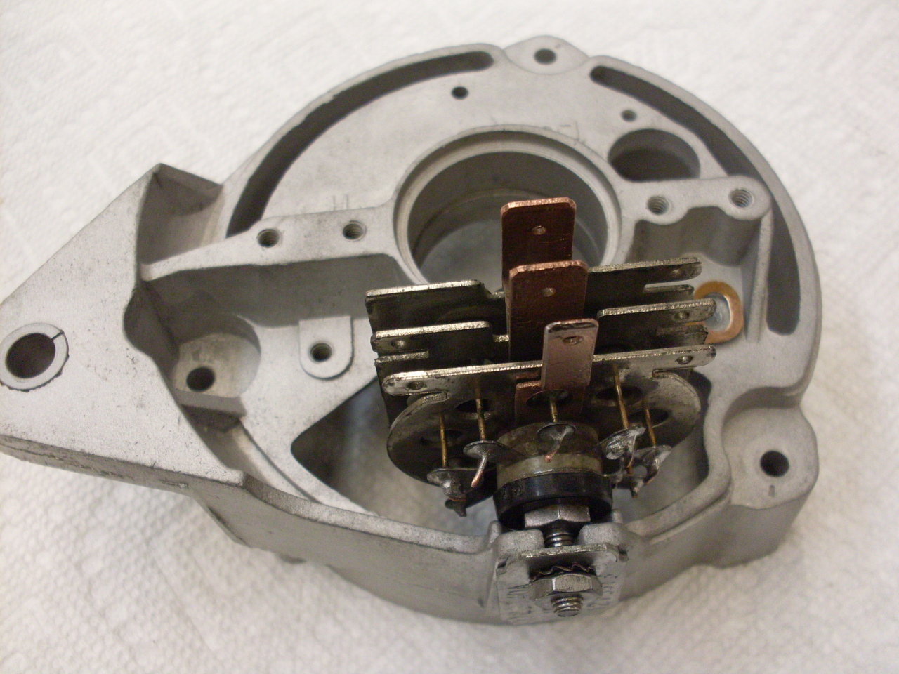
that can be a little intimidating. Among the electronic parts are
the three phase rectifier, the regulator module, and the plastic cap
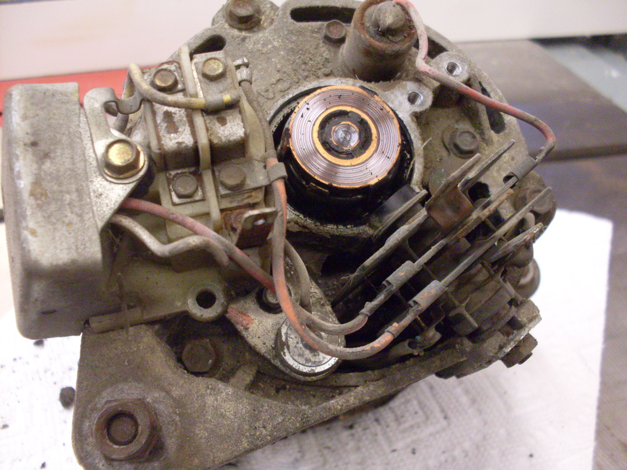
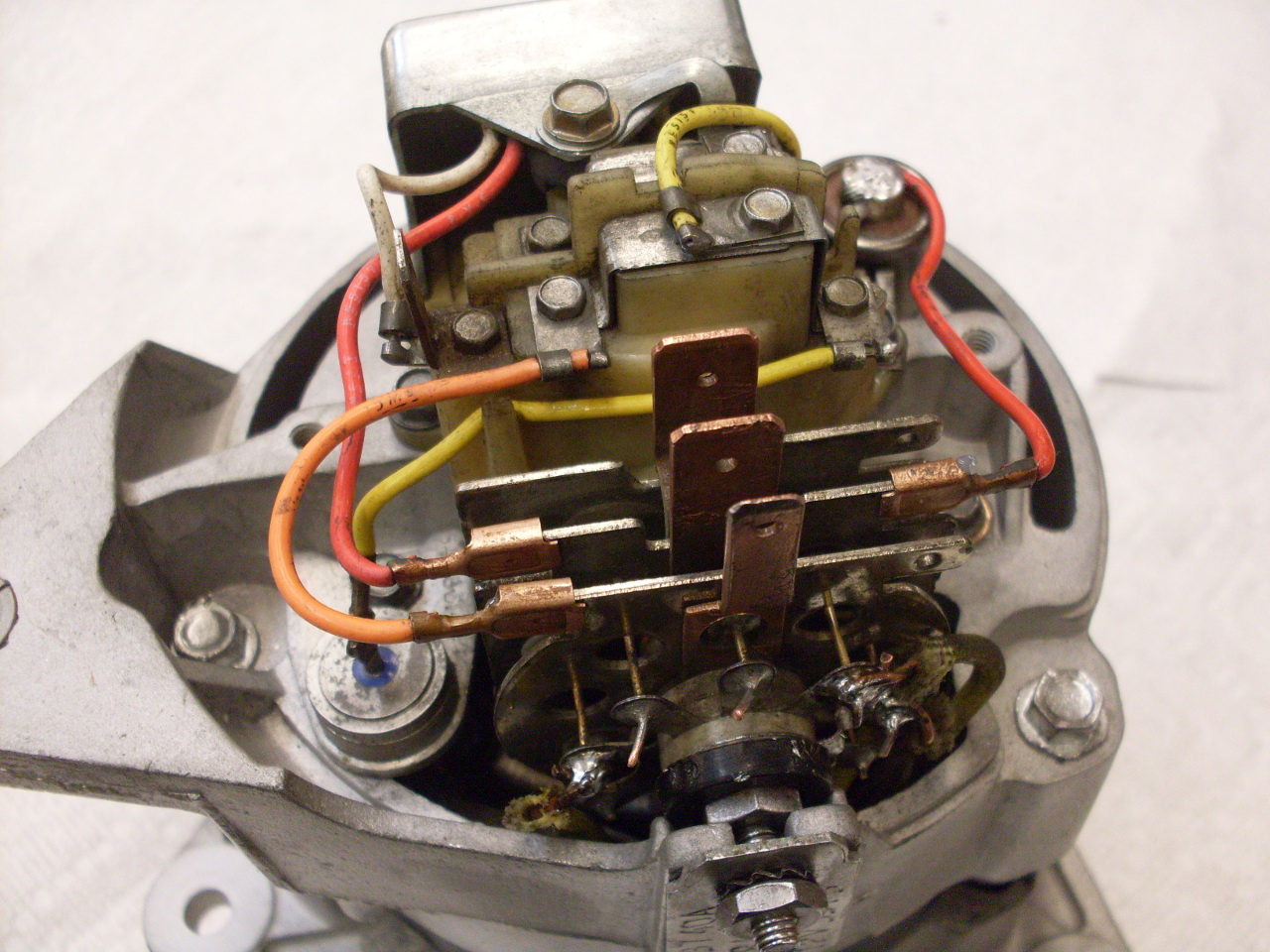
that holds the brushes for the rotor slip rings. The second pic
shows the brush box pulled aside to show the slip rings. The
regulator and brush box have to be removed by unplugging the spade
connectors. Obviously, it's a good idea to jot down a diagram of
how to connect it back up.
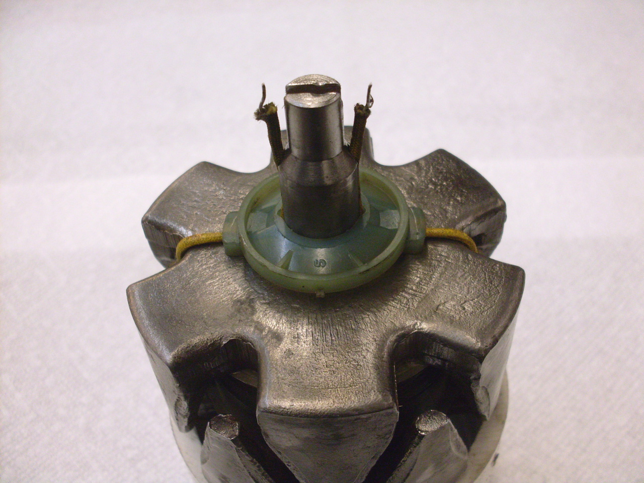
Removing
the aluminum housing from the slip ring end requires a thin wall
drift that fits over the slip ring molding and bears against the outer
race of the bearing below.

The rotor can then pe pushed out of the drive end bearing.

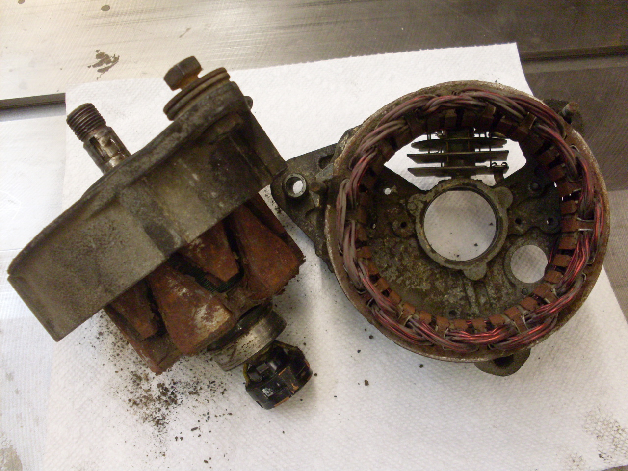
So here are most of the major parts.
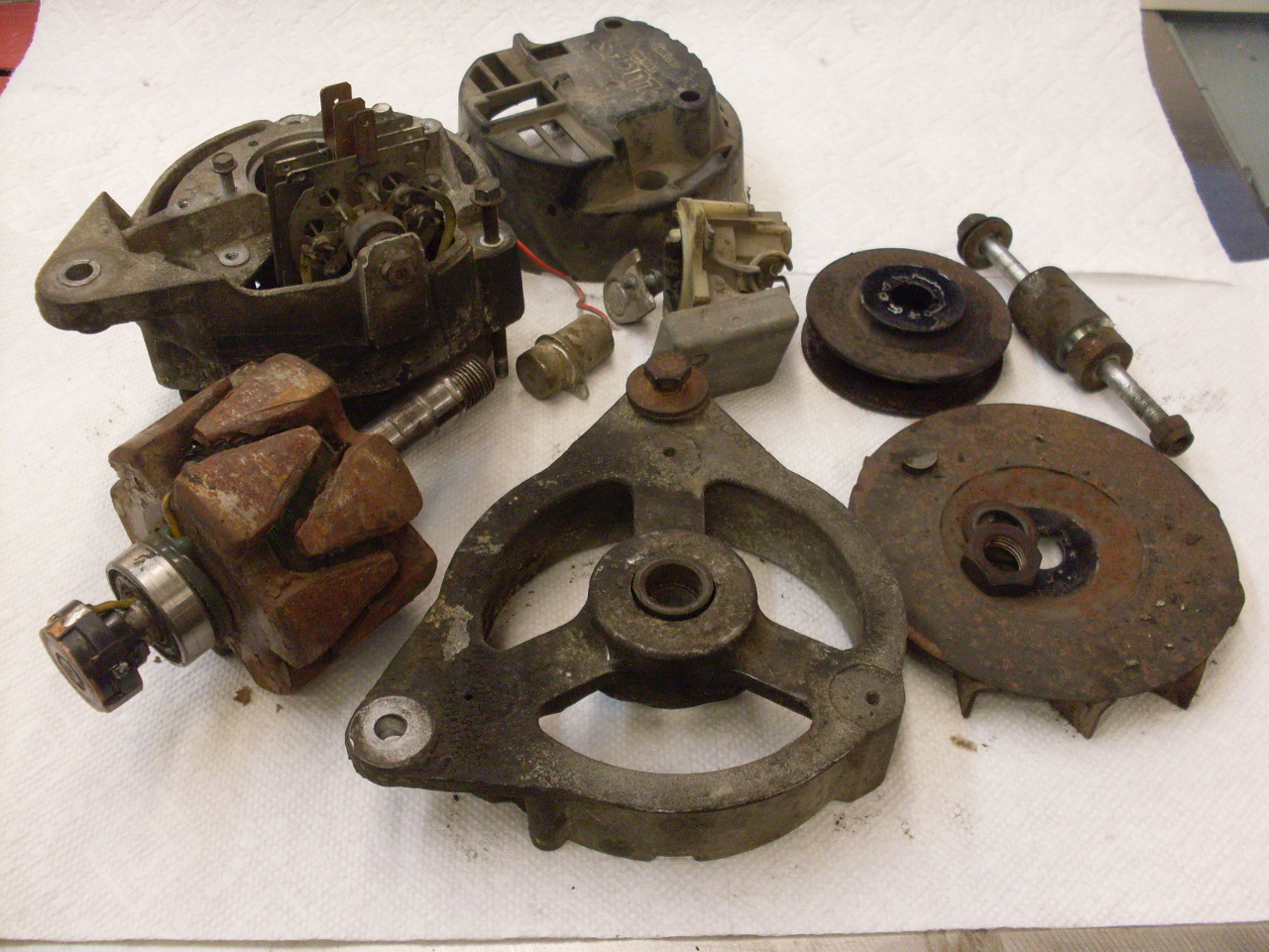
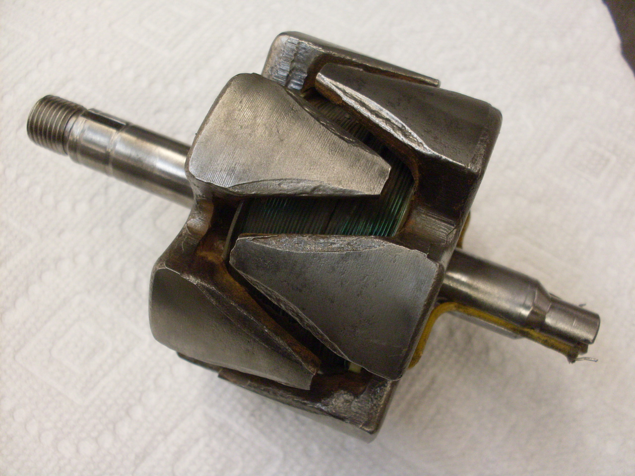
The
rotor bearing comes out of the drive end casting prett easily, but to
get the crusty bearing off the slip ring end of the rotor, the slip
ring molding has to come off. This requires unsoldering the two
wires from the field winding inside the rotor.
To
separate the stator windings from the slip ring end housing, the three
phase wires have to be unsoldered from the rectifier. This also
frees up the rectifier to be removed.
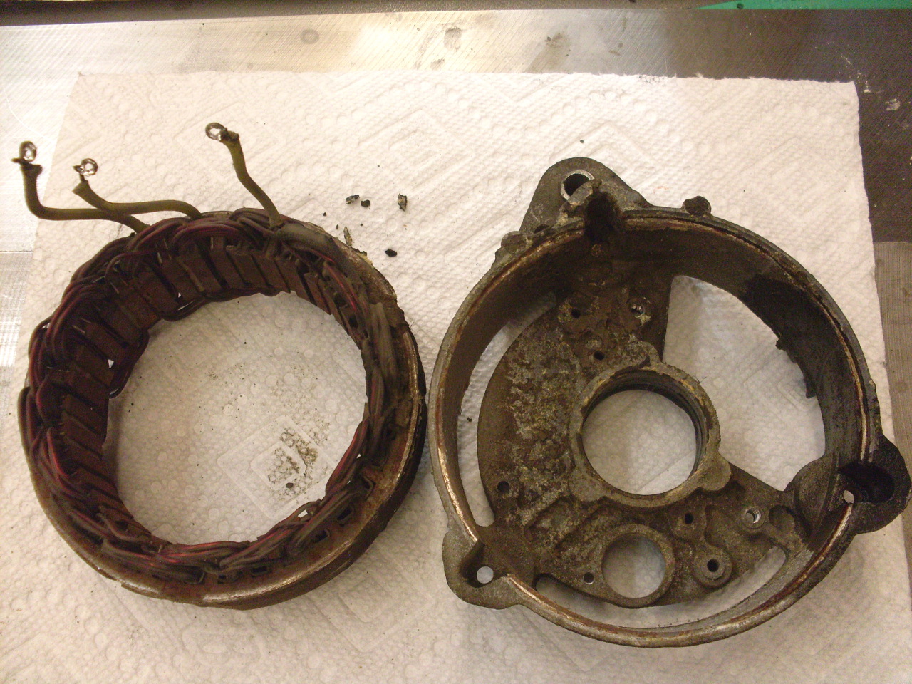
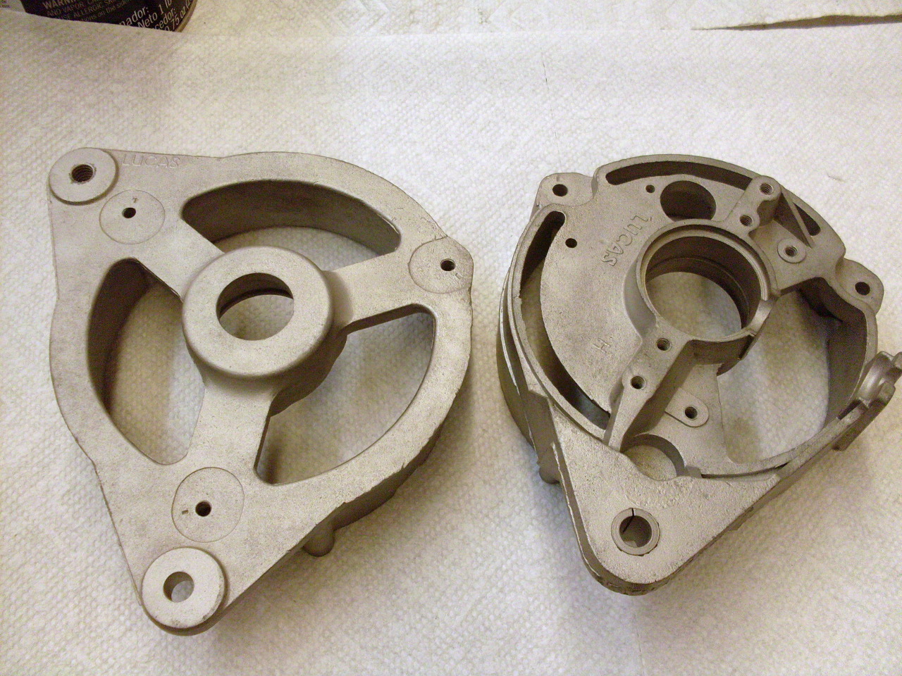
Here are some of the major parts cleaned up. The end castings, the rotor, and the stator.

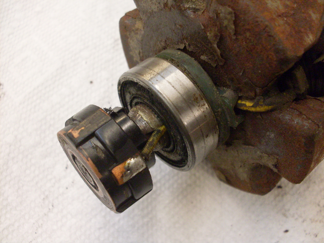
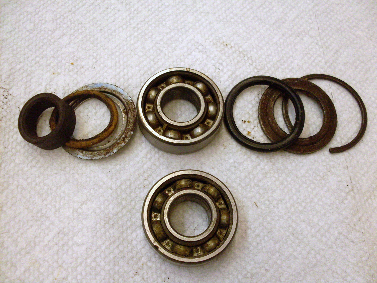
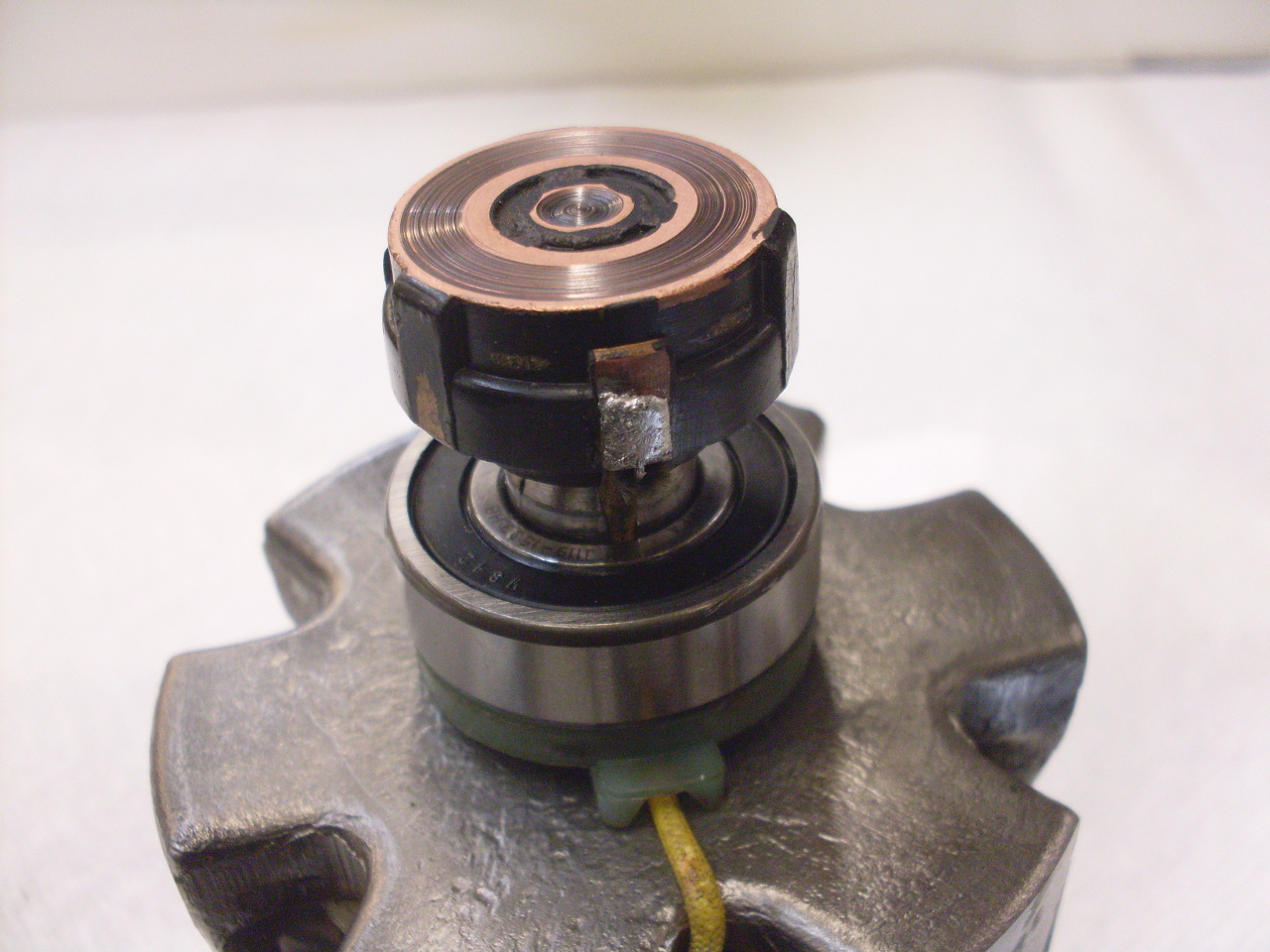
Here
is an intersting (and disappointing) thing about this alternator.
Notice that these are open (unsealed) bearings. The slip
ring end bearing did have a shield (not a seal) on the out-facing side,
and the drive side bearing did have an O ring to try to keep out crud,
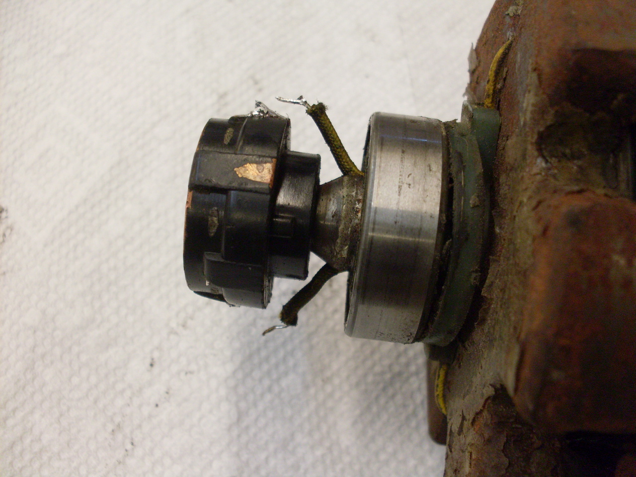
but the inside of the slip ring side bearing was completely open.
This alternater is by no means a sealed unit--in fact it
intentionally blows ambient air through the interior-- so it seems a
bit of a sloppy design to not use sealed bearings. This is
supported by the fact that the only apparent thing wrong with this
alternator is the bearings. Here is a great opportunity to upgrade this unit.
Cleaned
everything up, bought some new parts, and starting to reassemble.
First, there's a little guide for the field wires on the rotor.
The
two identical bearings are an easy to find standard industry size, but
I bought sealed units. I consider this a significant upgrade to
the alternator.

The
slip ring end of the rotor gets its bearing and the slip ring molding,
then the field wires have to be resoldered. Even though the slip
rings show some grooving, there is plenty of meat left on them, and
also on the brushes. Since the brushes weren't disturbed, they
should seat nicely back to the rings without significant additional
wear.

This is the three phase bridge rectifier. It converts the three sine waves from the stator coils to DC.

The
rectifier mounted in the slip ring end casting. I used a
dielectric grease on all the electrical connections. It is not
conductive, but protects the connections from moisture and oxidation.
Many of these connecrtions are dissimilar metals with a
likelyhood of getting wet, after all. I consider this another
upgrade of the alternator.

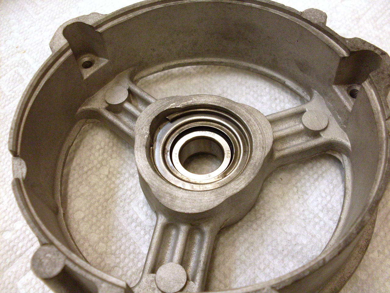
The
original open bearing in the drive end of the unit had some rings
intended to help keep grease in and deflect water (I guess), but they
were certainly not water tight. They are superfluous with the
sealed bearings, but have to be installed anyway to keep the stacked
dimension correct.

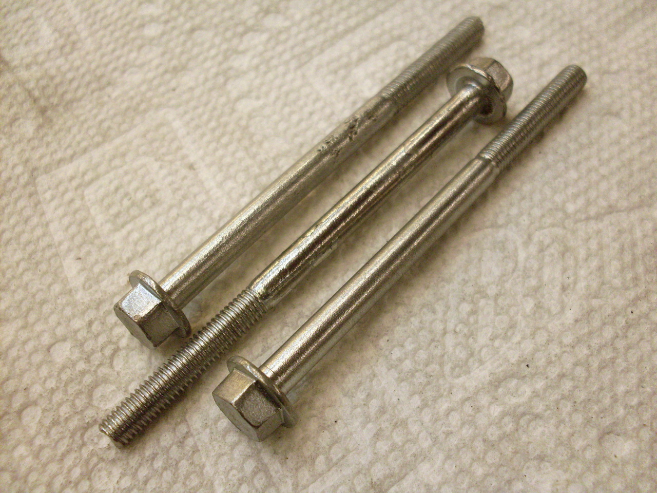
Ready to bring it all back together. The through bolts didn't appear to be plated, but I thought they should be.
With everything back together, the stator winding wires can be resoldered to the rectifier.
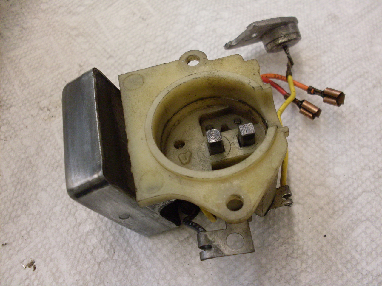
Then
it's just replace the brush box/control unit, and reconnect all the
wires using dielectric grease. Notice that little can-type thing
on the wire above the brush box (in the first pic)? It bolts to
the end casting and looks a lot like a heat sink situation.
Some heatsink compound here is a good precaution. Another upgrade.
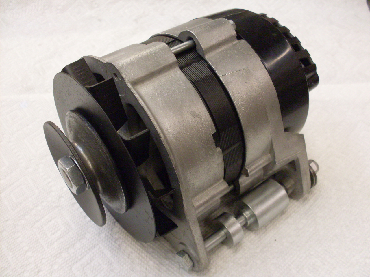
Add
the rear protective cover, the pulley and fan, and some freshly plated
mounting hardware, and this puppy goes on the shelf until install time.
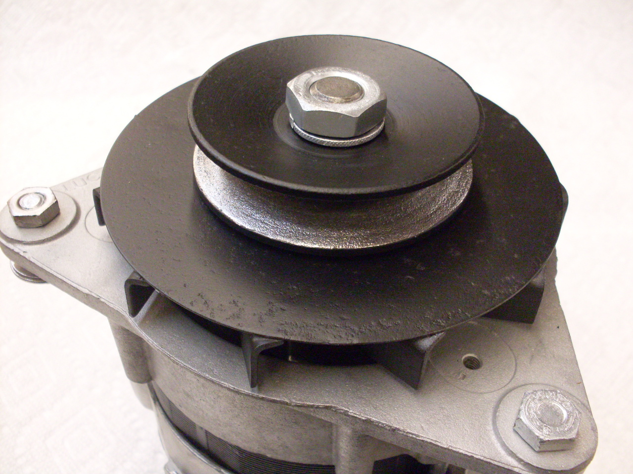
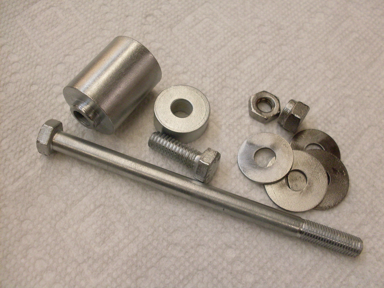
Total cost for the rebuild/upgrade was under $15 for the two bearings and a couple of O rings.
To other TR6 pages
Comments to: elhollin1@yahoo.com