I'm
still mainly working on getting body panels in shape, but this involves
test fitting some of the larger lighting assemblies like head and tail
lights. To make sure these assemblies are in final form, I
decided to take a branch and get all the outside lighting up to snuff.
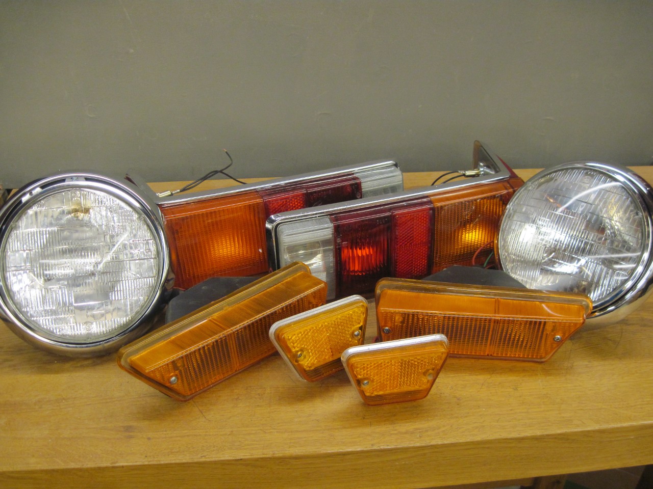
Tail Light
Assemblies
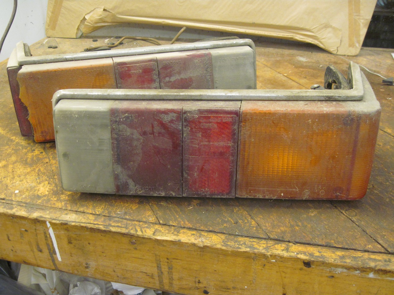
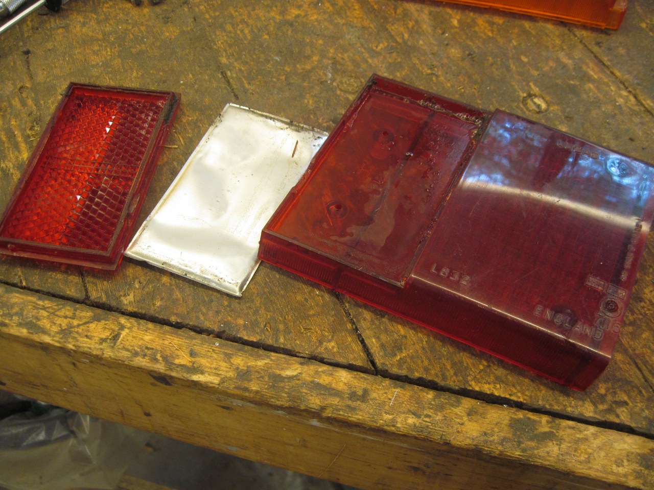
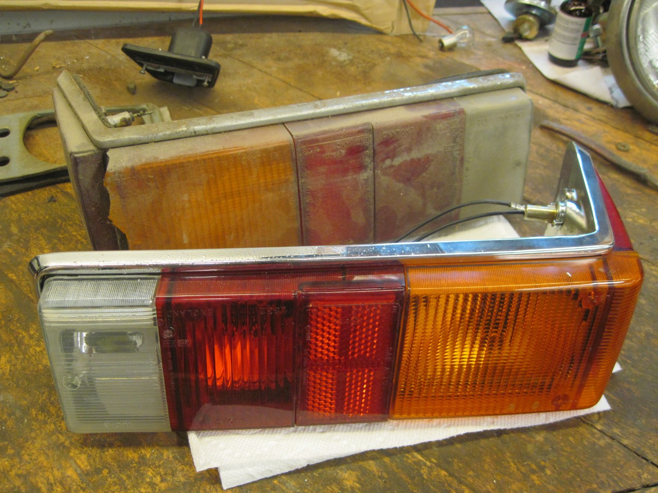
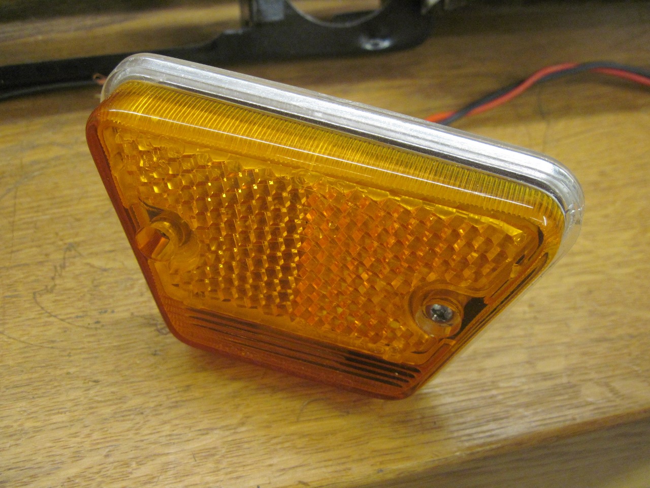
On
the TR6, a single tail light assembly carries the tail, stop, reverse,
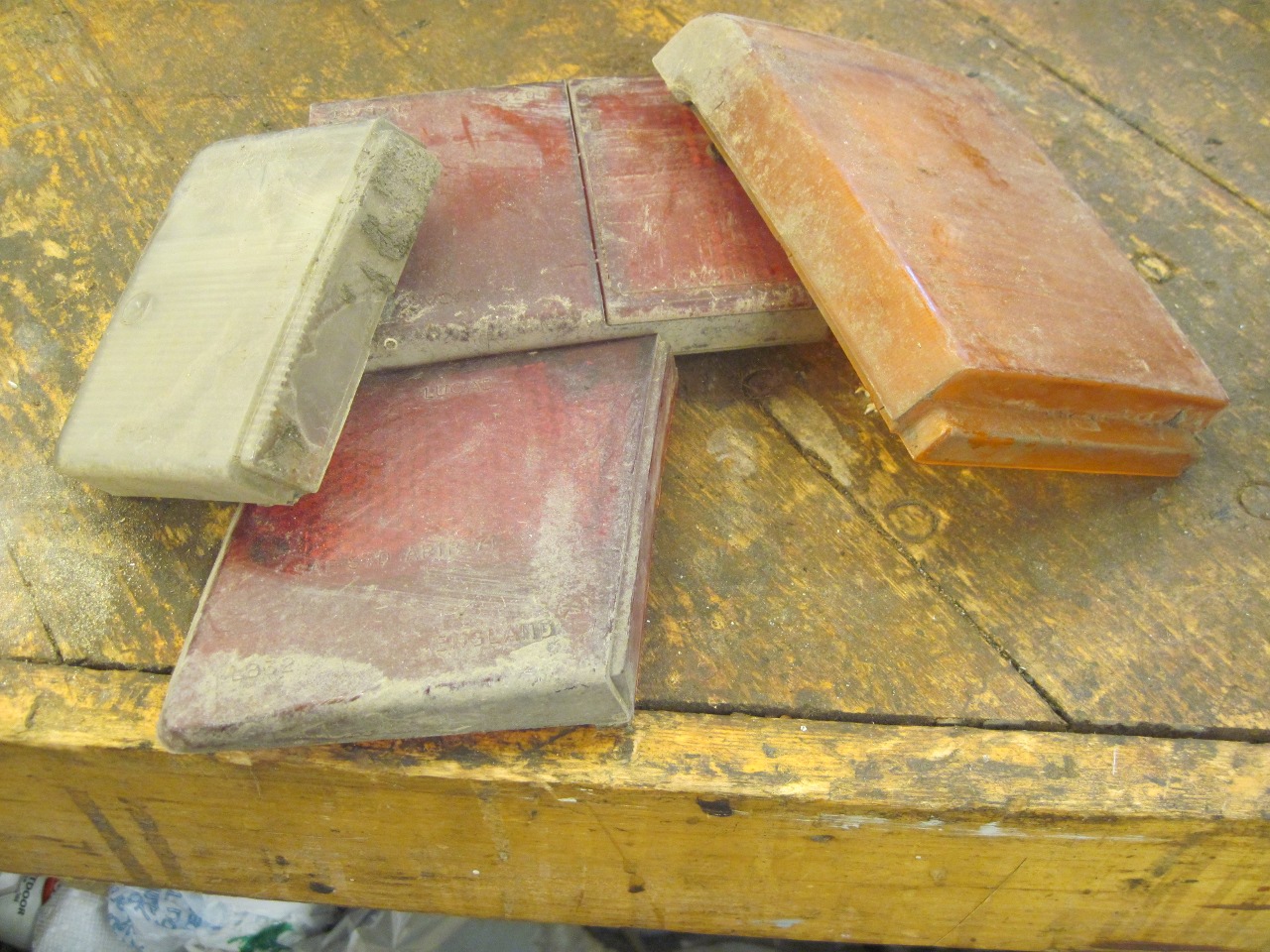
and turn lights, as well as a side marker light. It is a very
clean looking unit with separate lenses of appropriate color that fit
together to look like a single lens with multiple colors. My
lights had 40 years of grime on them and one of the lenses was broken, but
they were otherwise complete and intact.
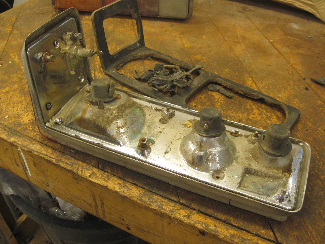
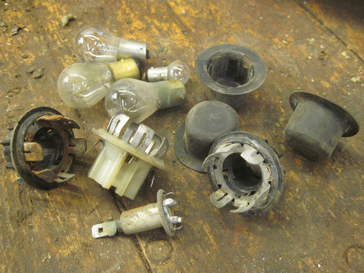
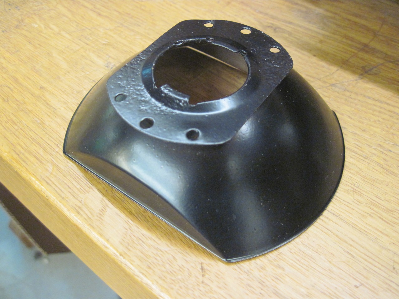
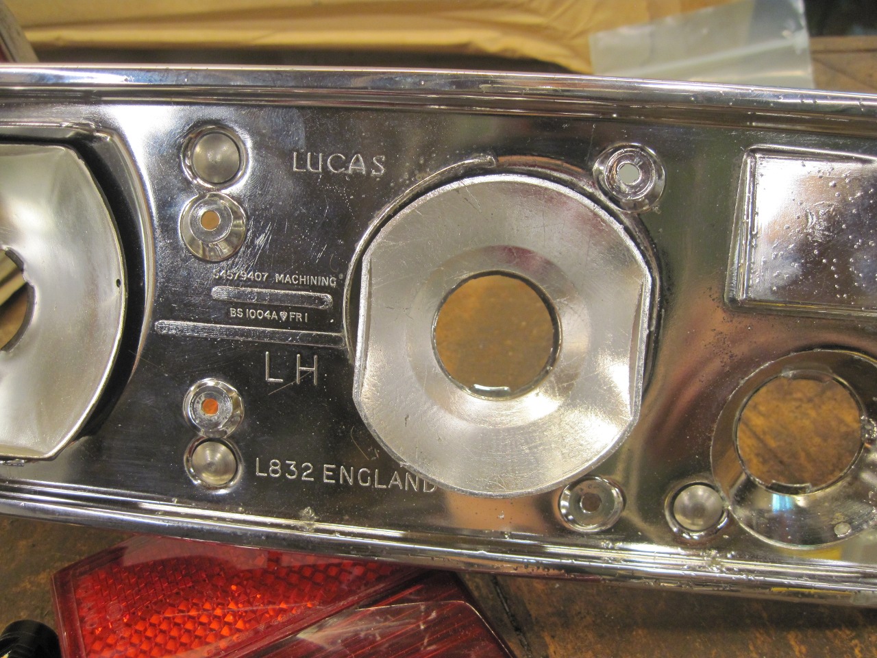
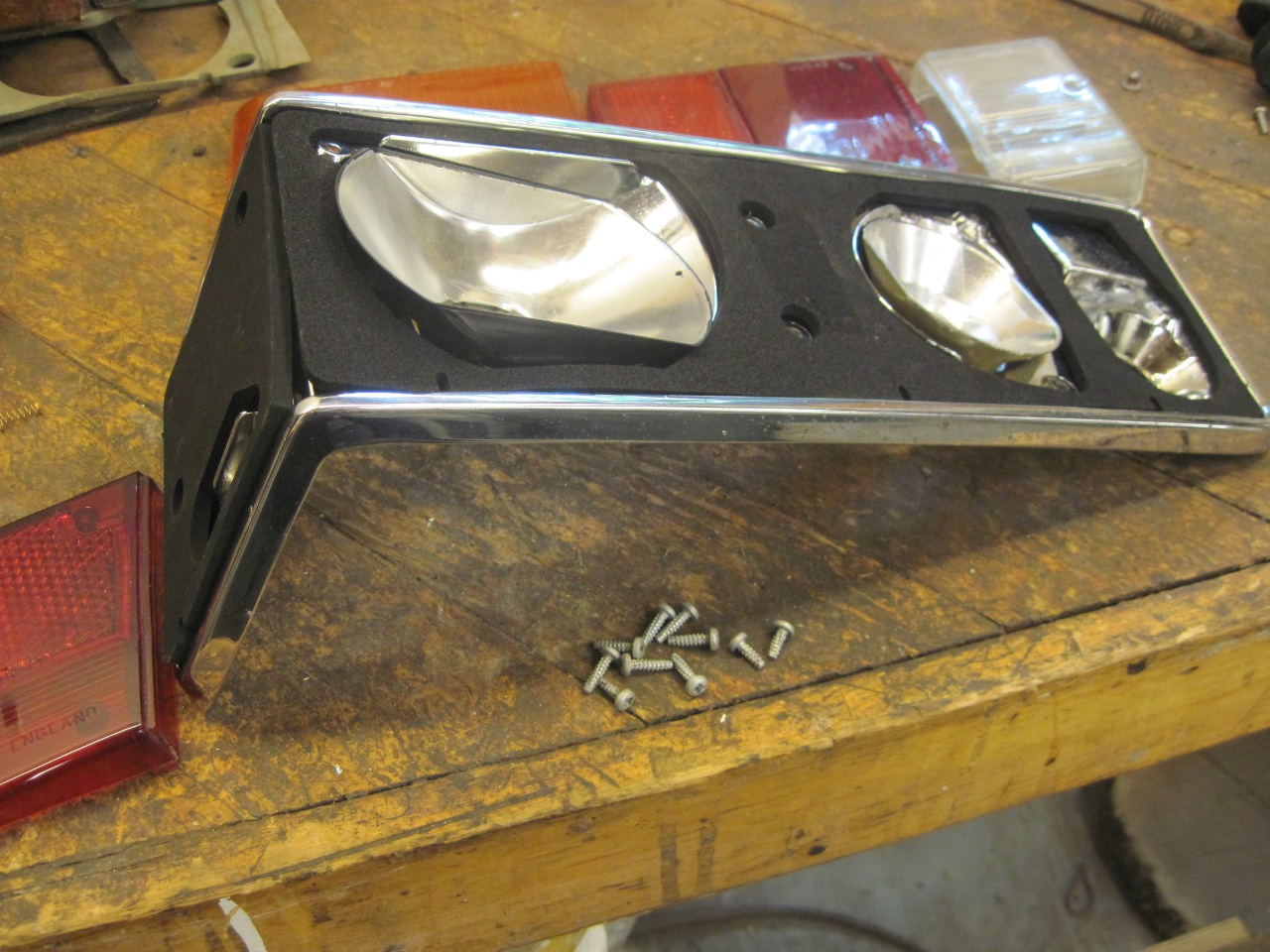
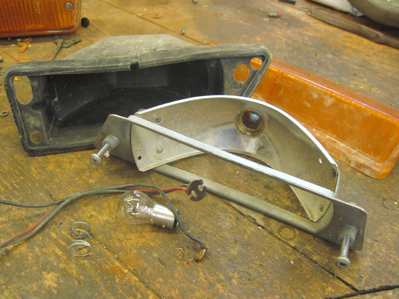
The
heart of the assembly is a chrome plated pot metal casting.
The
casting carries separate parabolic reflectors for the stop/tail and
turn signal lights, but has molded-in reflectors for the backup and
side marker lights. All of the lamp sockets are removable
from
the backside (accessible from the boot) without removing the assembly or
the lenses.
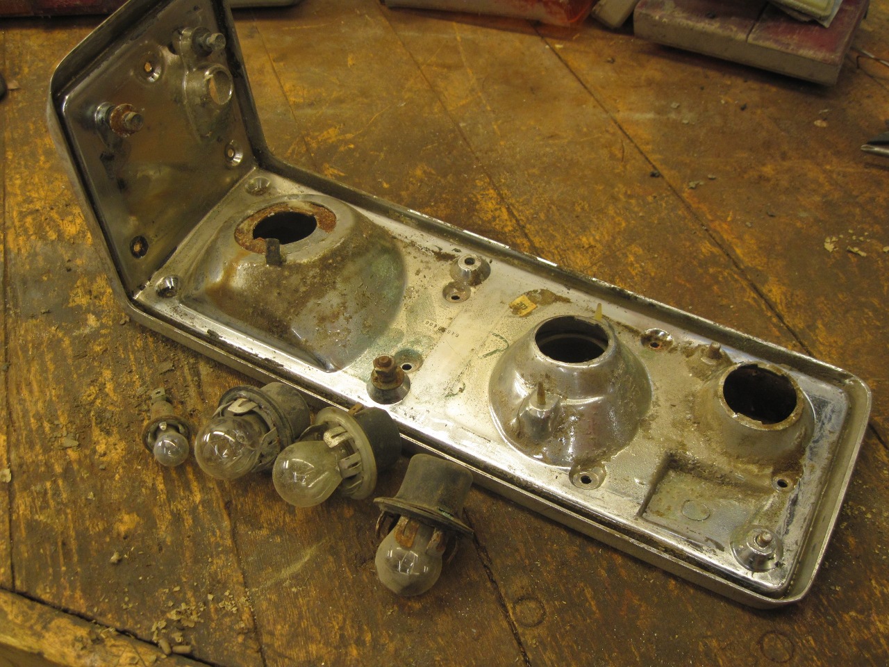
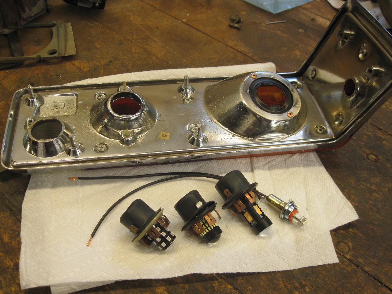
Sockets
for the Stop/tail, the turn signal, and the backup lamps are similar,
except that the stop/tail holds a standard 1157 dual filament lamp,
while the others hold 1156 lamps. The marker light has a
simple
bayonet socket for a common 1895 lamp.
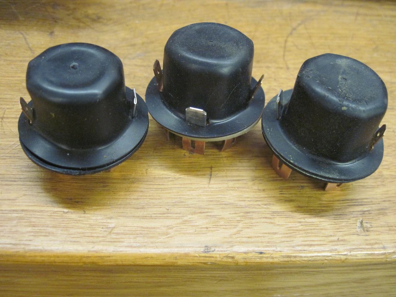
Though
rubber boots try to protect the sockets from moisture, they sometimes
fall short. A few of my sockets had significant rust, which
of
course means that the protective zinc coating was long gone.
I
believe these sockets are available through some of the usual
suppliers, but in keeping with the overall spirit of this project, I
preferred to try to save the ones I had. To protect the steel
parts of the sockets from future corrosion, some sort of durable
coating would have to be applied. I typically zinc plate
small
steel parts to protect them, but in this case there are copper parts in
the socket. I didn't think I could realistically take the
socket
apart or selectively plate the steel, so I landed on copper plating,
which seems appropriate for an electrical device. So, after
removing all the rust, they got a coat of copper. I only had
to
do this for the sockets on one side of the car.
Now,
one of the prime directives on the overall TR6 project is to improve
the electrical system wherever possible. In many cases, this
means
improving grounding. I'd wager that a sizable portion of TR6
electrical problems are caused by bad grounds. It was a
common
practice in this era to use the body of the car as a return path for
many of the electrical circuits. While this works passably well
when the
car
is new, there are approximately one bazillion places on this car where
electrical return paths depend on intimate metal contact in joints that
are
also susceptible to corrosion.
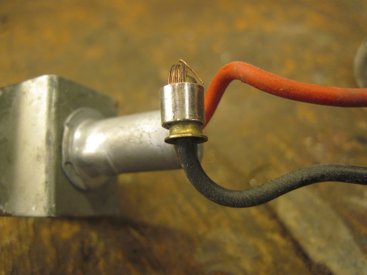
Take these tail light
sockets for example. In the return path, there is a copper
finger
that presses against the base of the bulb. That finger is pinched by the
plated steel ring that mounts the socket. Spring fingers on
the
steel ring press against another steel plate that is mounted to
the main tail light casting. From there, there is a copper
rivet
that holds the plate to the main tail light casting, and also a male
spade connector. This connector gets a real copper wire that
grounds the main casting. With all the unsoldered dissimilar
metal joints in the path, just add a few condensation cycles, and we
start to have a compromised ground return.
I've seen some very
innovative approaches to mitigating this situation, including soldering
the copper finger to the steel ring in the socket. While this
is
ingeneous and a good step in the right directrion, what I really wanted
was an explicit ground terminal right on the socket.
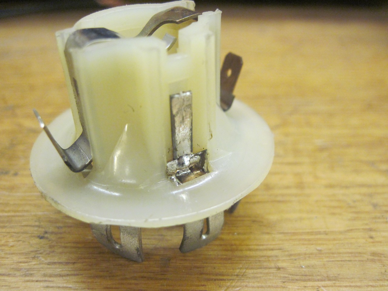
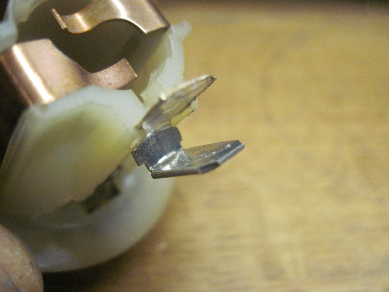
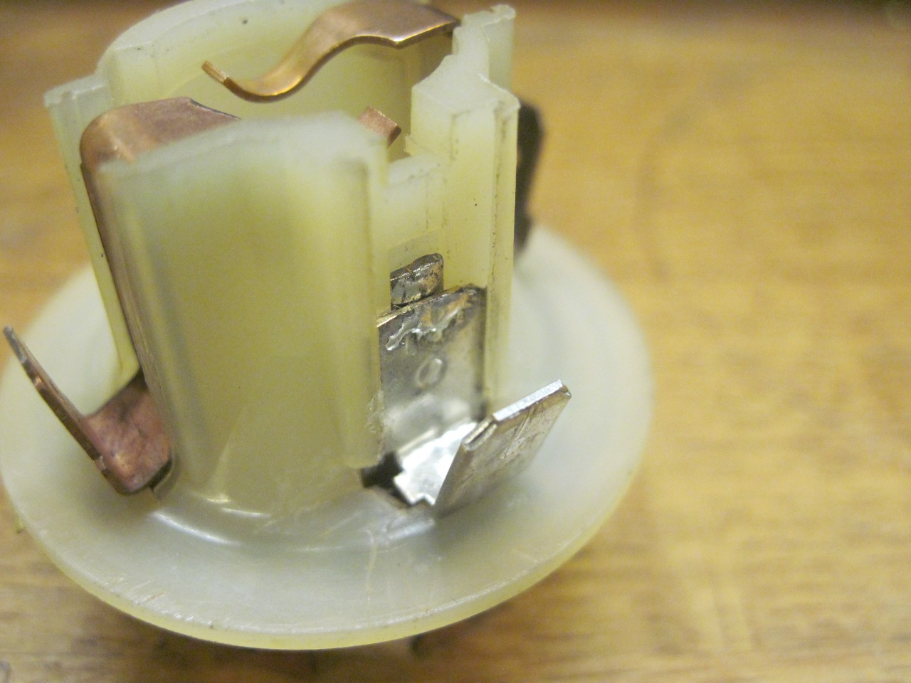
What really got me
thinking, though was when I realized that these sockets were designed
to have a ground terminal. There are four positions
around the socket for connection terminals. Only one is used
for
the 1156 sockets, and two for the 1157 sockets. The ground
finger
that contacts the bulb base is mounted in one of the other positions,
but doesn't have a terminal.
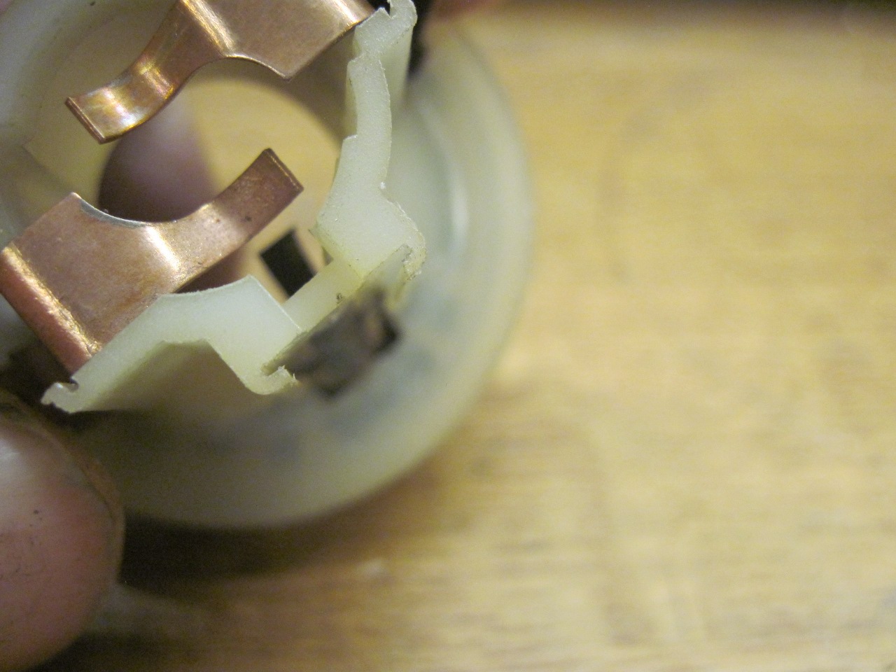
Here's
how I remedied the situation. I cut a little copper strap
about
1/2" long and just narrow enough to fit in a groove above the ground
contact. This got soldered to the ground contact.
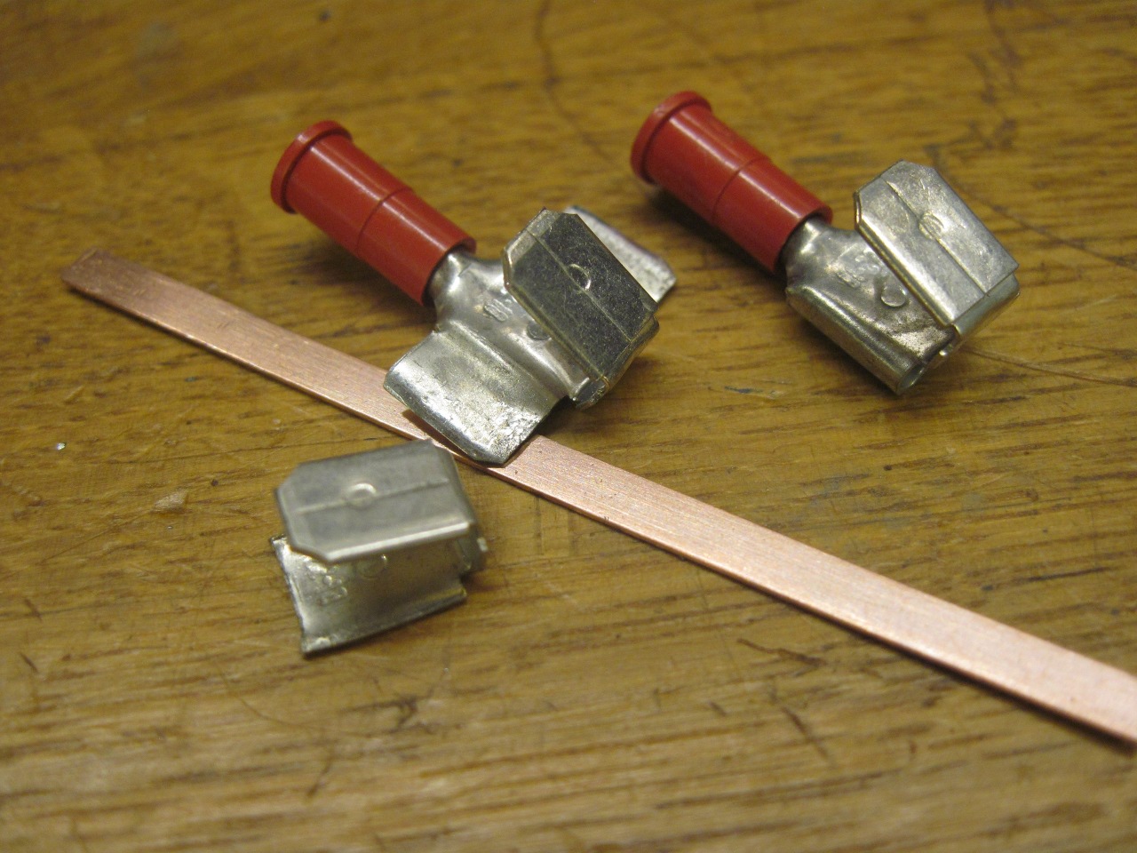
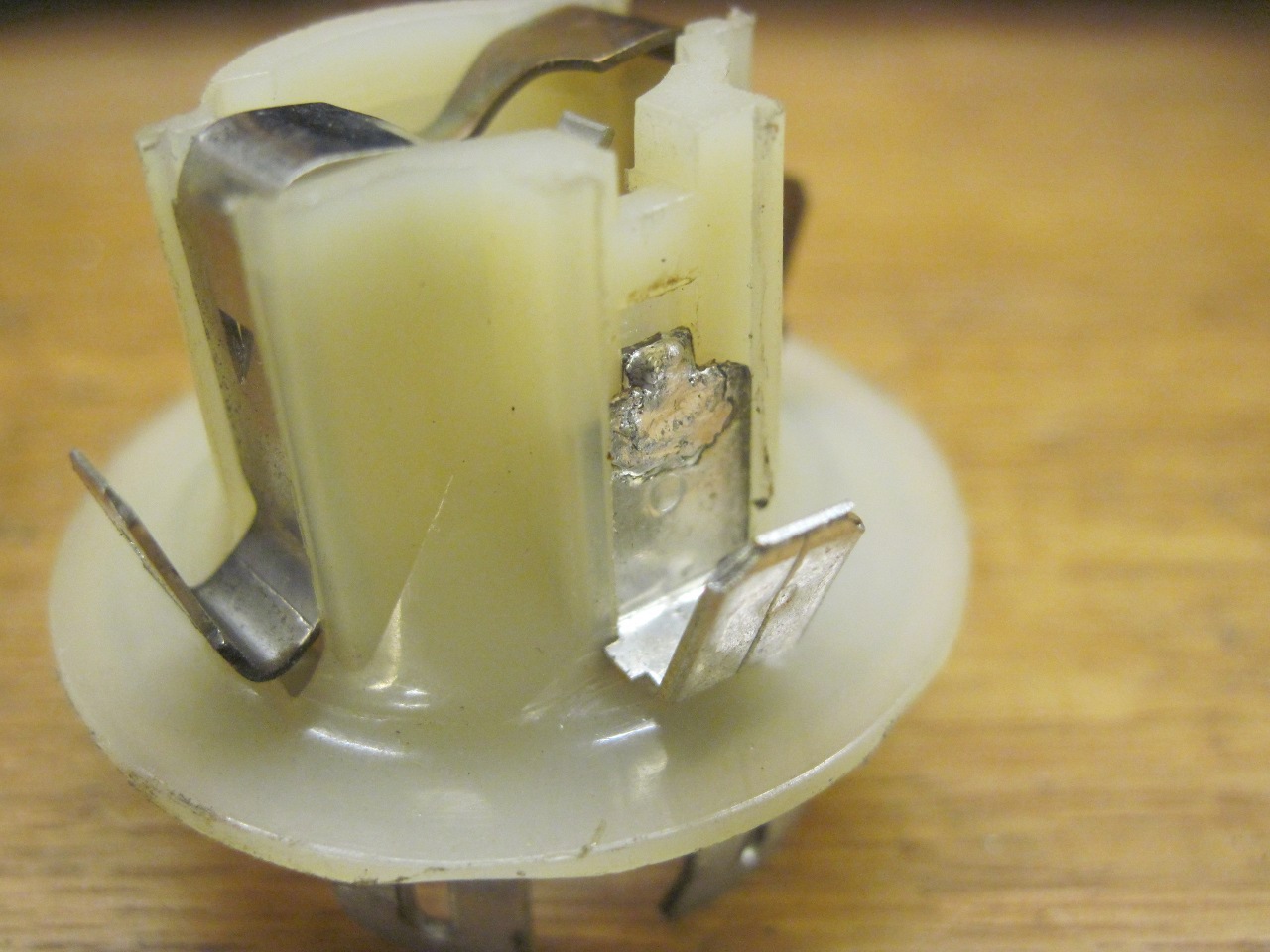
Then
I modified some of these little "piggyback" spade terminals into a
terminal that had a face that would neatly slide down into the socket
just like the other terminals.
Then soldered the terminal to the copper strap.
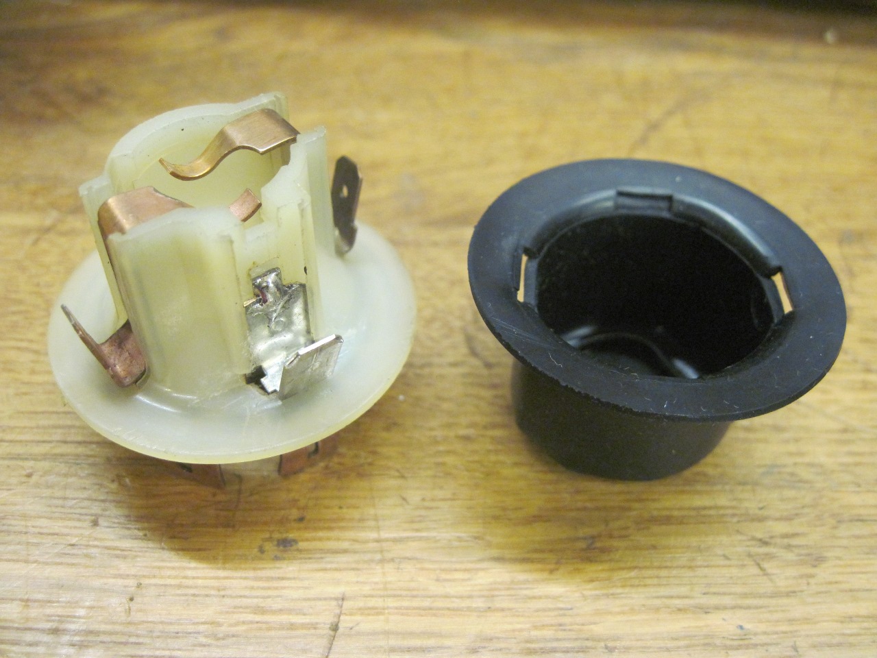
In another little serendipidous moment, I discovered that the rubber
boots already had provision for the extra terminal.
All three upgraded (well, I claim it's an upgrade) sockets for one
side of the car:
The
side marker socket was different--it's for a smaller 1896 lamp, but
also did not have a ground terminal. Luckily, I was able to
find
a two-wire socket that would fit the hole perfectly.
Being pretty happy with how those sockets turned out, I moved on to
other little issues with the tail lights.
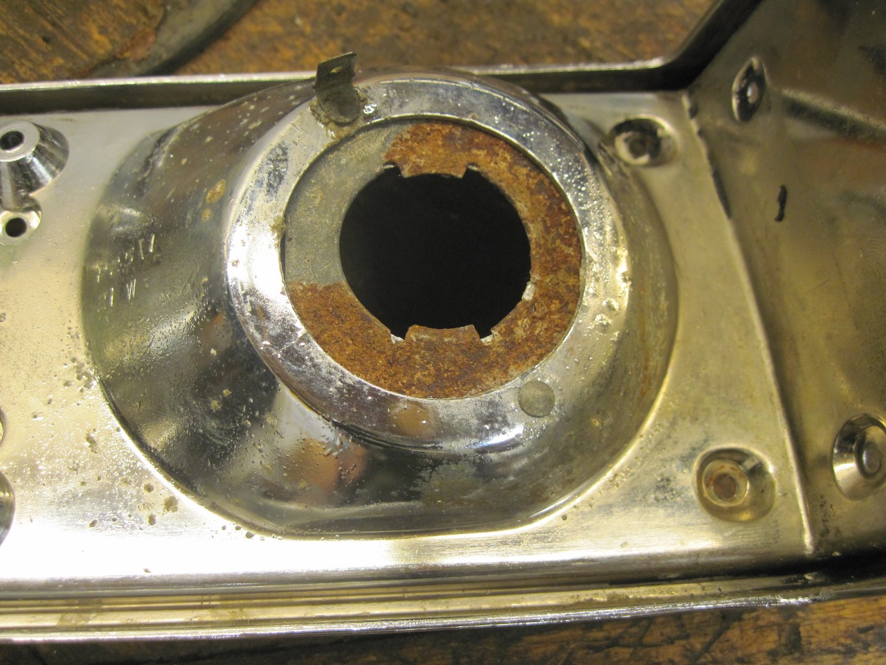
Here
is the steel plate that the spring fingers of the socket mate with.
Even though it's not in the electrical ground path
any more,
I wanted to take care of the rust.
That plate holds the aluminum turn signal reflector, and the two are
attached to the casting by two rivets.
I
would normally try to re-plate the steel part, but I wasn't sure I
could separate the plate fromt he reflector without maiming the
delicate reflector, so I left them together , removed the rust, and
powder coated the plate and the backside of the reflector.
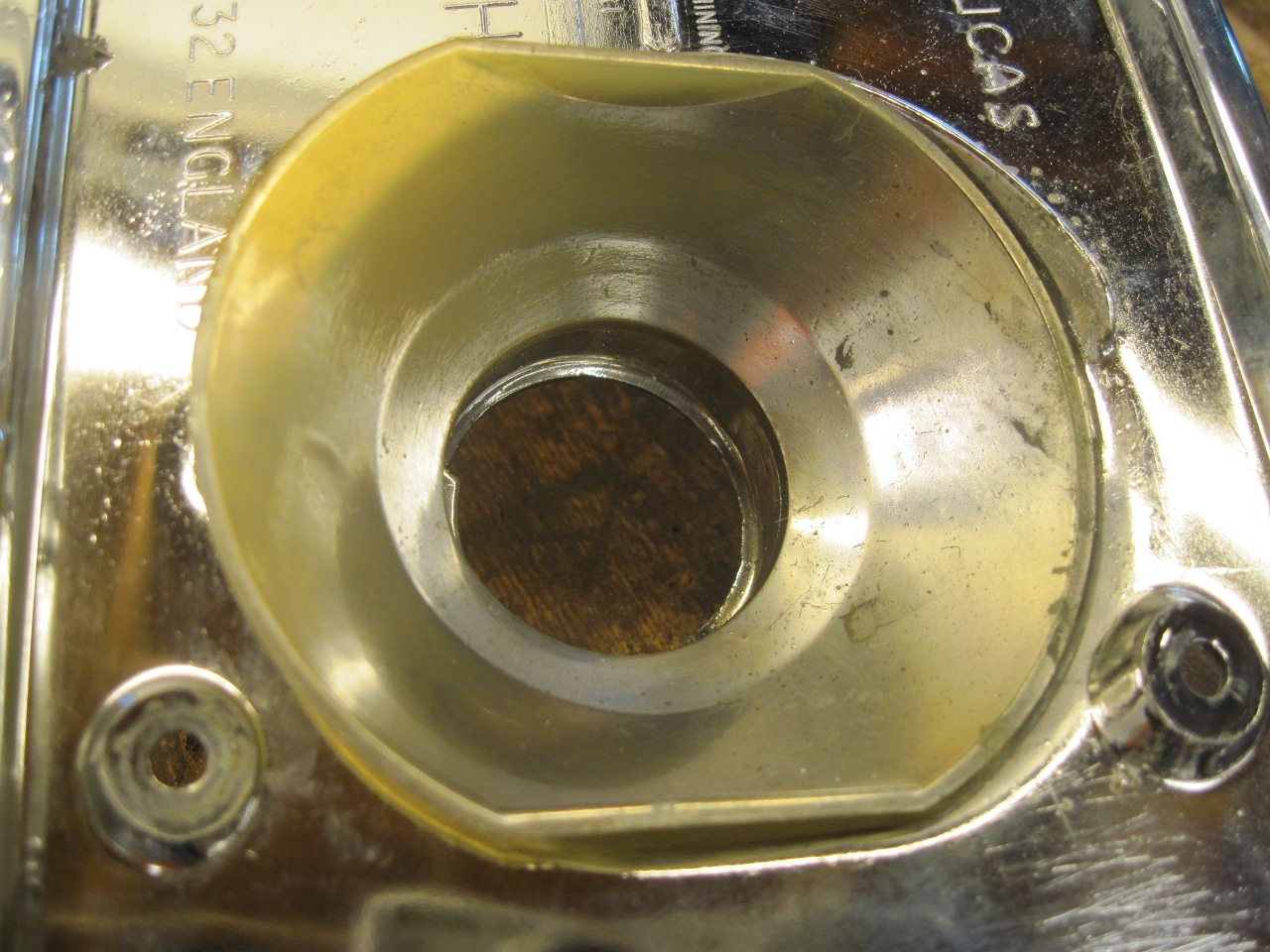
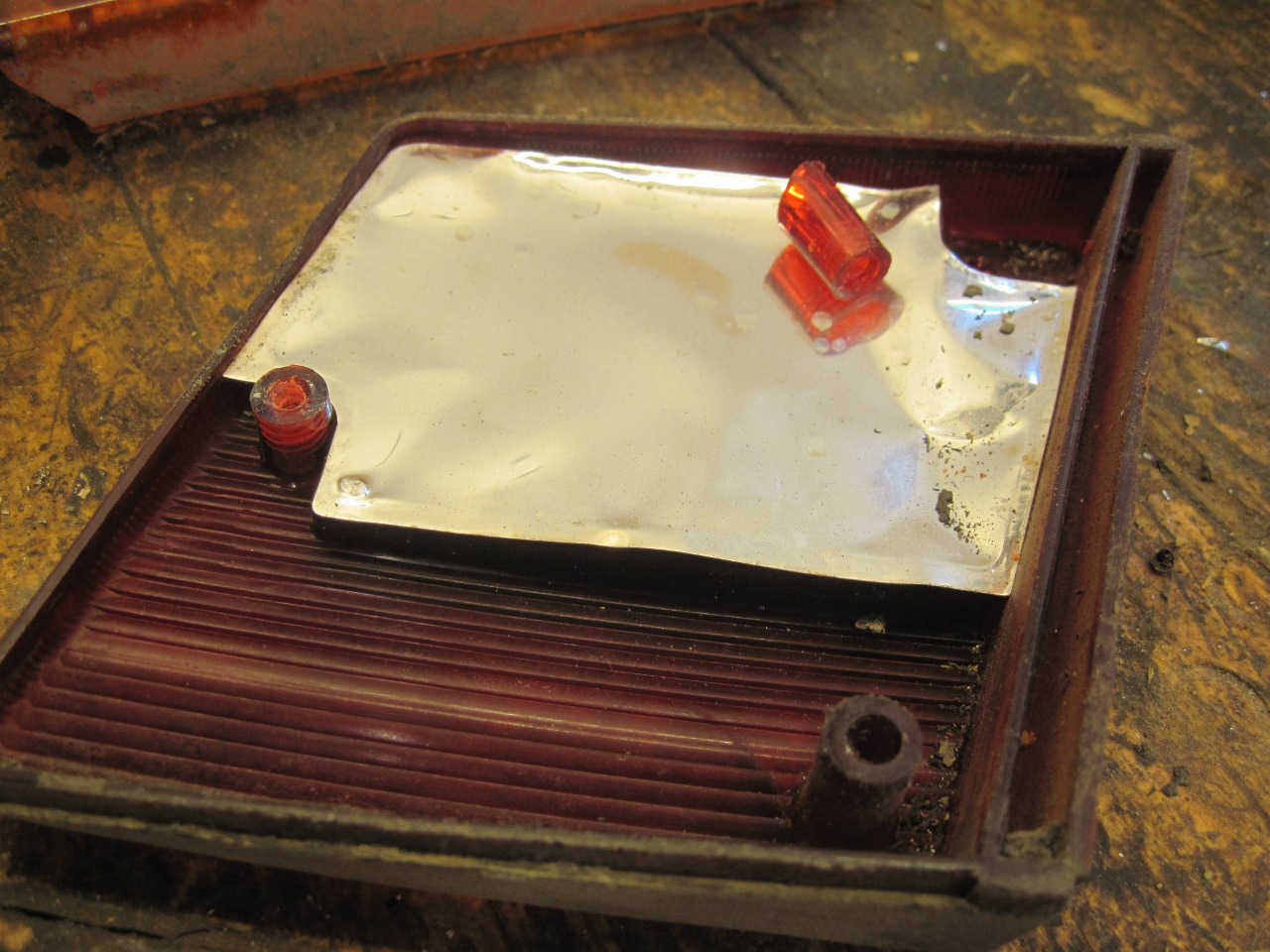
Then
there was the stop/tail reflector. It is plastic with a
mirror
finish--I guess either chrome plated or vacuum deposited aluminum.
Either way, the reflective coating was very thin, to the
point of
being able to see through it in places. It wasn't nearly as
reflective the one on the other side of the car.
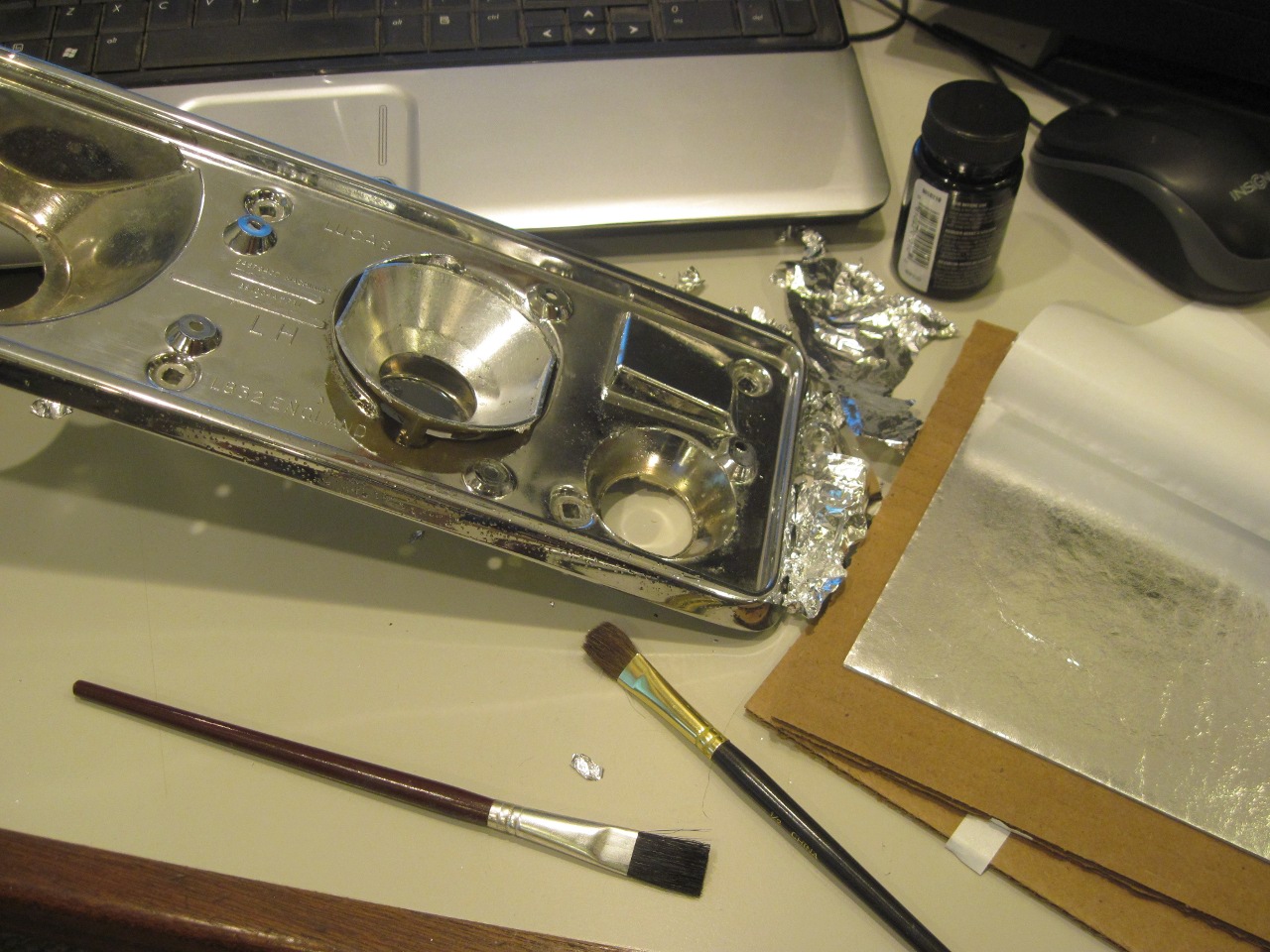
I
thought a lot about this, looked at a lot of silver, even "chrome"
paints, but none of them were very mirror-like. I ended up
learning a new technique and applied aluminum leaf to the reflector.
Aluminum leaf is analogous to gold leaf (but, you know,
cheaper).
It is like aluminum foil but much thinner--only about half a
micron (about 20 millionths of an inch). The result is still
not
a mirror, but better than any paint I saw.
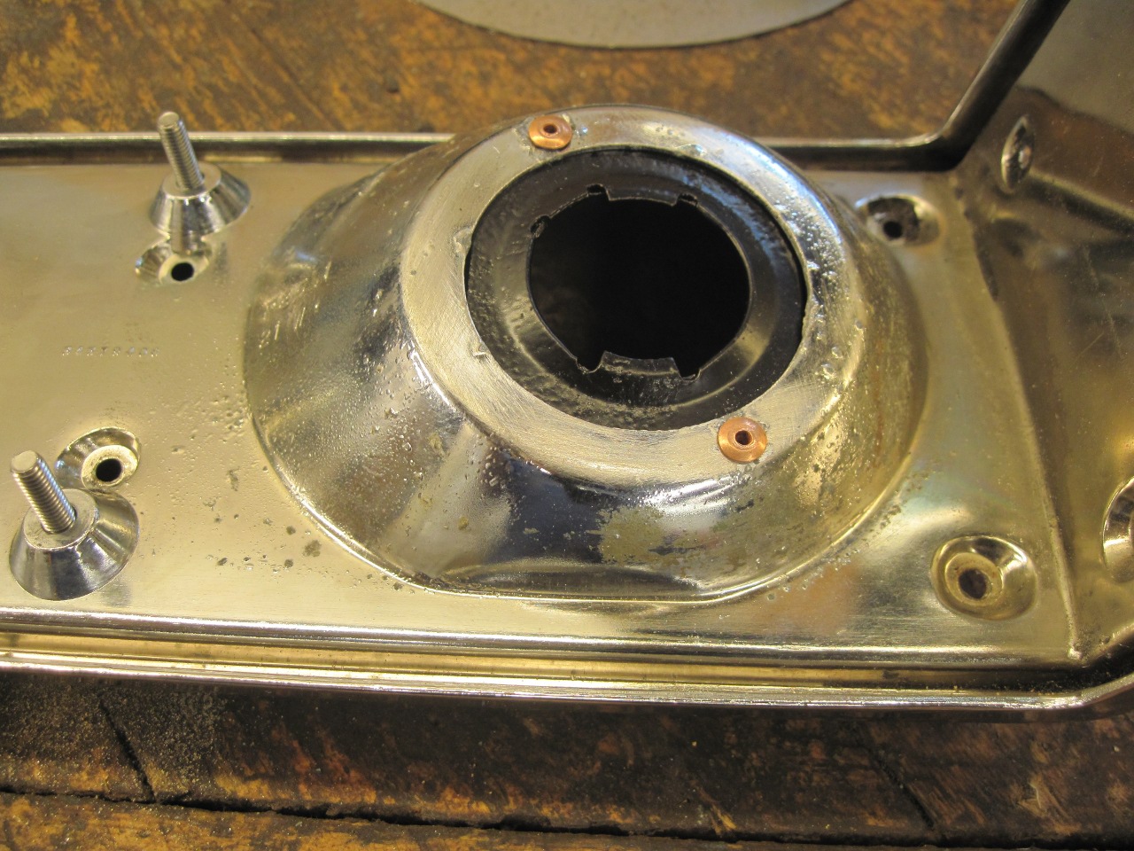
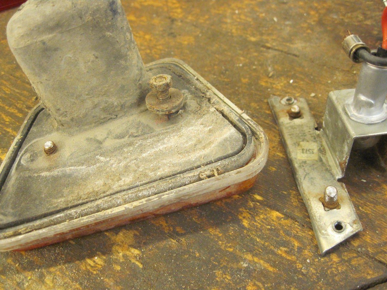
One
other thing had to be sorted out on the tail lights. Some of
the
mounting studs were seized and twisted off during removal.
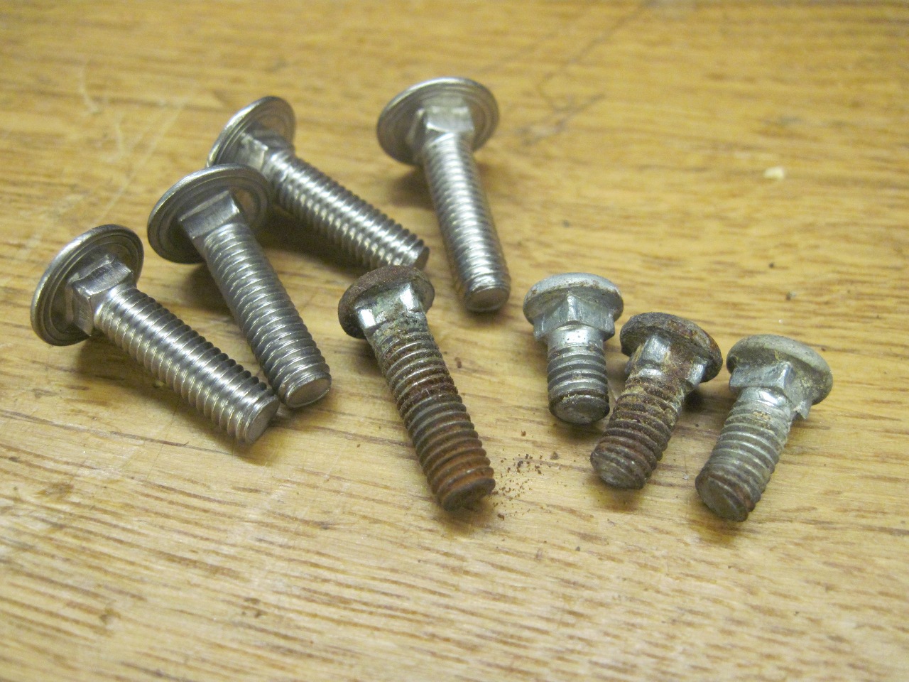
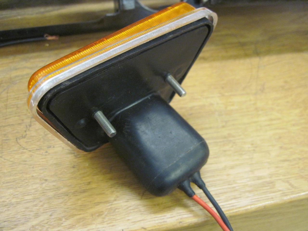
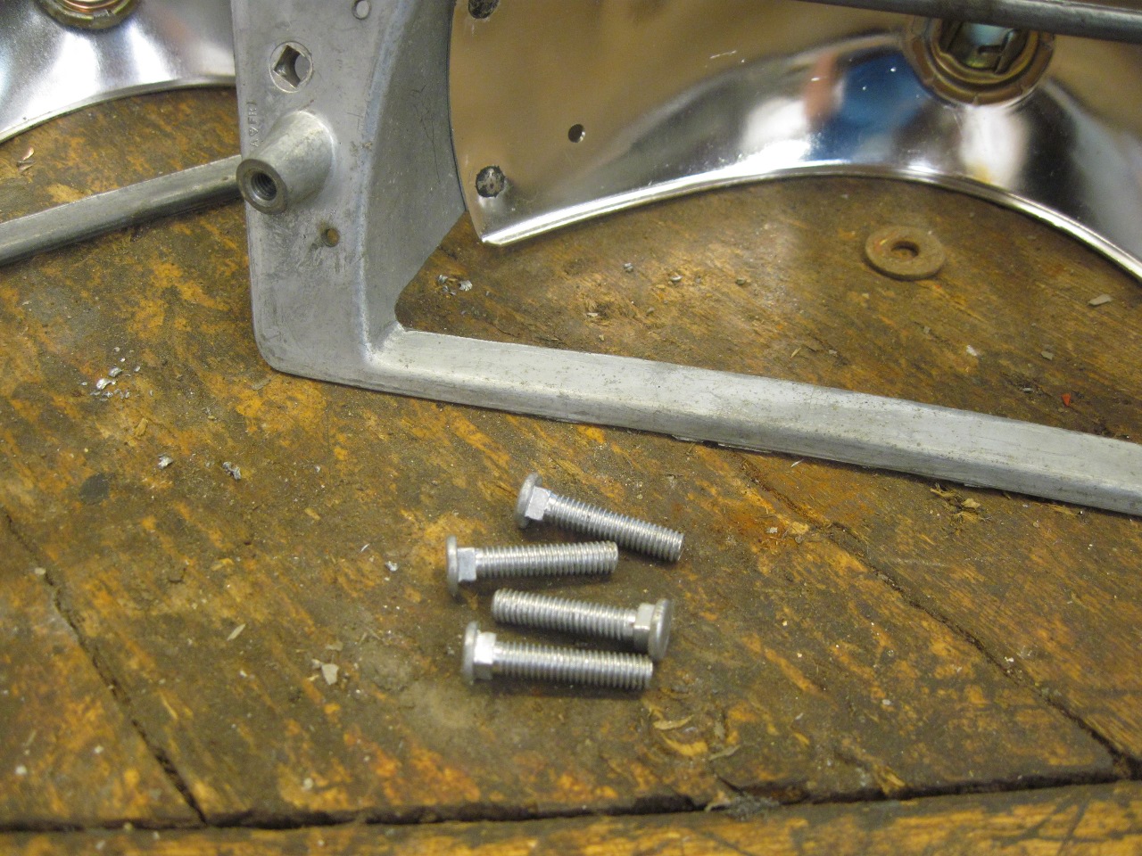
The
studs have a short square shank under their small heads, and are
pressed into the soft pot metal casting. It didn't take much
to
pop them out. I was able to find some small carriage bolts
that
match the 10-32 threads of the originals, but with a bigger head.
The dimension of the square was very close. Most
places,
the carraige bolts worked fine, but I had to reduce the diameter of the
head in a few places. Also, the new bolts are stainless, so
corrosion souldn't be a problem.
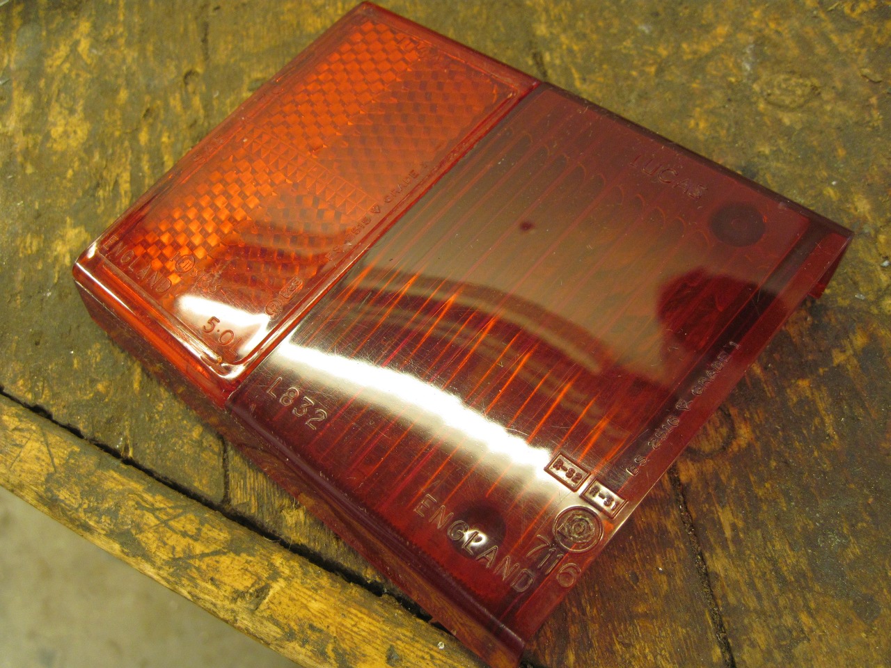
Then
it was on to the lenses. I was able to clean up and polish
all
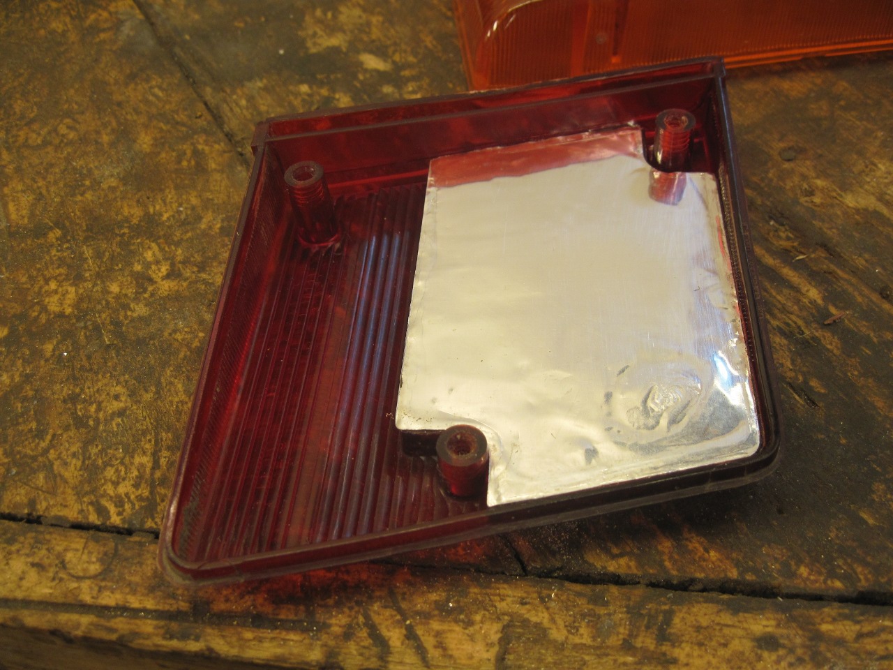
the lenses except the broken one, which I replaced. The only
other thing regarding the lenses is that some of them have built in
reflectors. The reflectors are just thin aluminum, like a
heavy
foil. Most of them had come loose and had to be flattened and
re-glued. The reflector in the stop/tail lens is behind a
glued-on cap that has to be popped off.
There was also a tricky repair of one of the fastening bosses on one of
the side marker lenses.
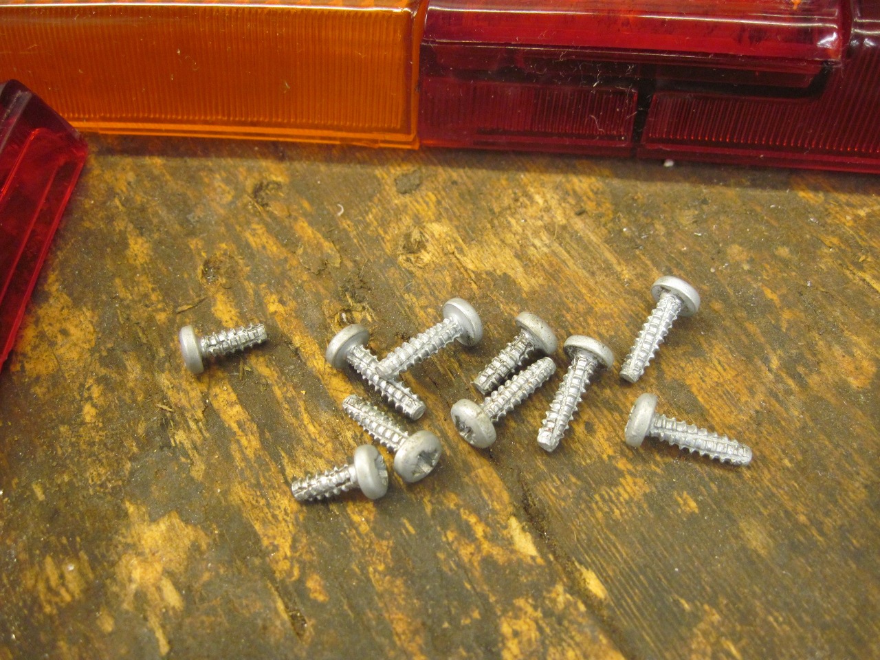
Since
I was reusing most of the old lenses, I had a small concern
about
stripping the fastening threads in the soft plastic. The best
way
to reduce the risk is to re-use the original screws so there won't be
any additional thread cutting. The original screws were
pretty
rusty, but cleaned up OK.
As with most things that come in pairs, I did one side first.
The second side is always much faster.
Now, on to the lamps themselves. In addition to improving the
grounding system on the car, I wanted to experiment with reducing the
electrical load. By doing this, I might be able to
accommodate new loads like seat heaters without having to upgrade the
alternator. One way to reduce load is to change out
incandescent bulbs for LED units, which produce light much more
efficiently. There is a dizzying selection of LED
replacements for the ubiquitous 1156, 1157, and 1895 incandescent
lamps. I bought a few, more or less at random, though I did
try to select those with higher lumen output. One other quirk
about LEDs that is different from incandescents is that they come in
multiple colors, and the colors are not achieved by filters.
The colors are a result of the actual materials that make up
the LED. So for LEDs it doesn't make sense to buy a white LED
and then put it behind a red filter which would block all but the red
light. A red LED on the other hand emits light predominately
in the red part of the spectrum, so a red filter won't block much of
it. LEDs made to replace automotive incandescents come in
red, amber, and a couple of shades of white.
One concern is whether the LEDs would look as bright as the
incandescents. Here are some clips of side-by-side tests.
In each test, the incsandescent lamps are on the left, the
LEDs on the right.
As for the electrical load savings, here is the current drawn from one
side with all the lights on. The current reads a little over
five amps, but note that the voltage has dropped from 14 to 10 volts.
That's because the power supply has a max output of five
amps, and it folds back the voltage as necessary to not exceed that.
The calculated current at the full 14 volts would be north
of seven amps.
And here is the situation with all LED lamps on. The current is
just over one amp (look quick--the camera scrambles to screw down its
aperture to adjust to the sudden bright lights).
So
it appears that the LED lamps will reduce the maximum electrical load
from the back end of the car by around 12 amps. Maybe I can
actually use my seat heaters!
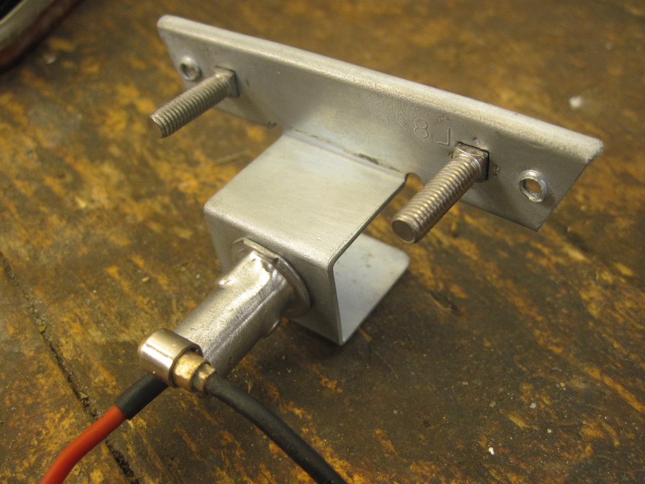
Front Side Marker Lights
The
front side marker lights are pretty simple--a metal frame that carries
the lamp socket, a rubber boot that doubles as a gasket, and a lens.
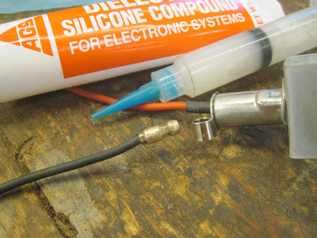
The
good news is that the marker socket has a ground terminal. The
bad news is that it uses one of those cheesy fake bullet connectors
where the wire just wraps around a little metal sleeve. That will
be easy to fix.
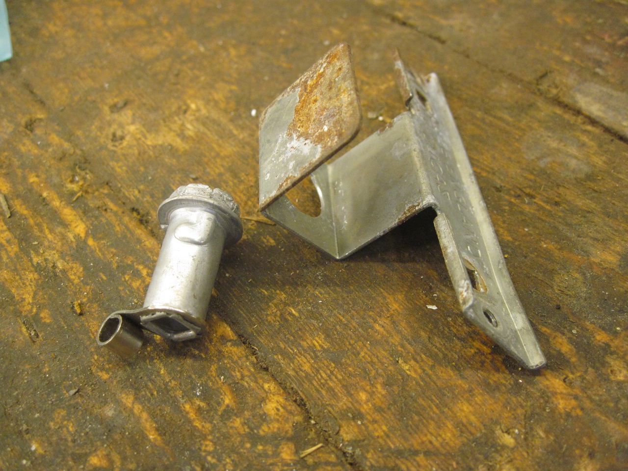
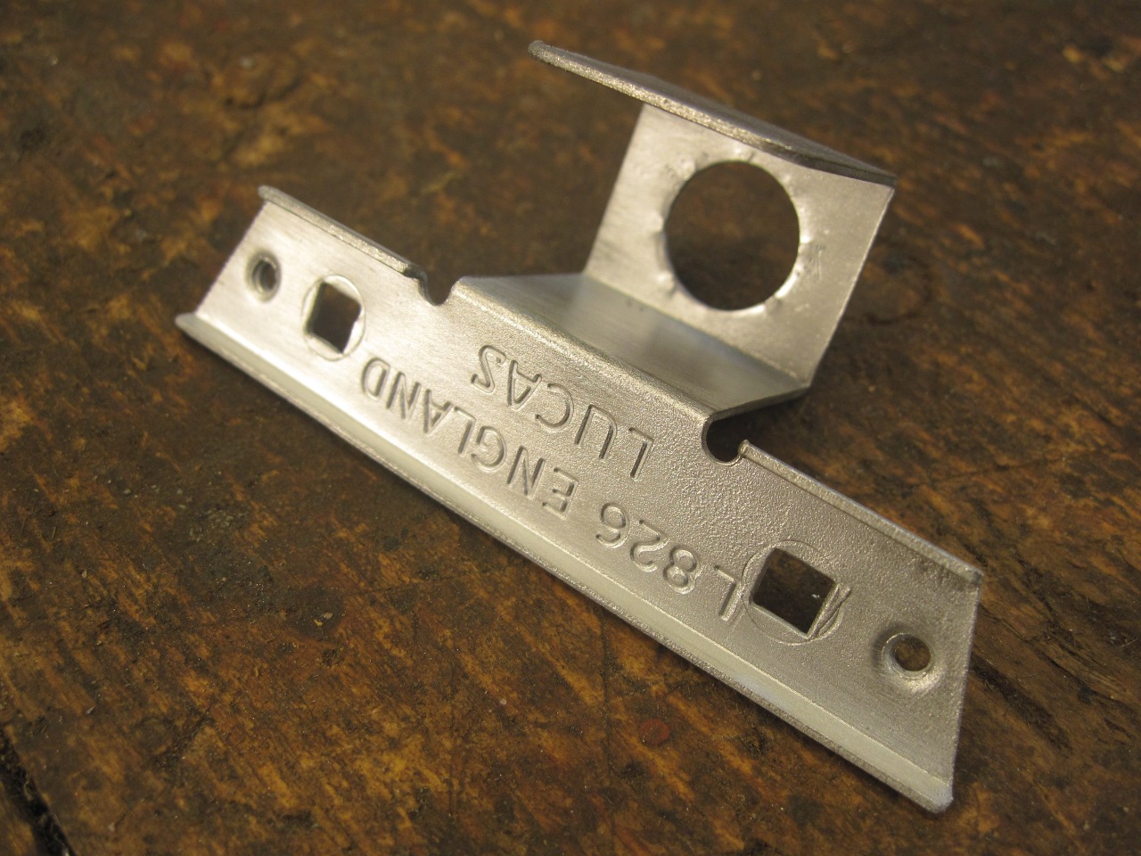
There
was some corrosion on the metal frame, and it was a little distorted so
I separated the socket from the frame, straightened it up, and replated
it.
Reassembled the socket with a real soldered bullet, and pushed in new carraige bolt studs like for the tail lights.
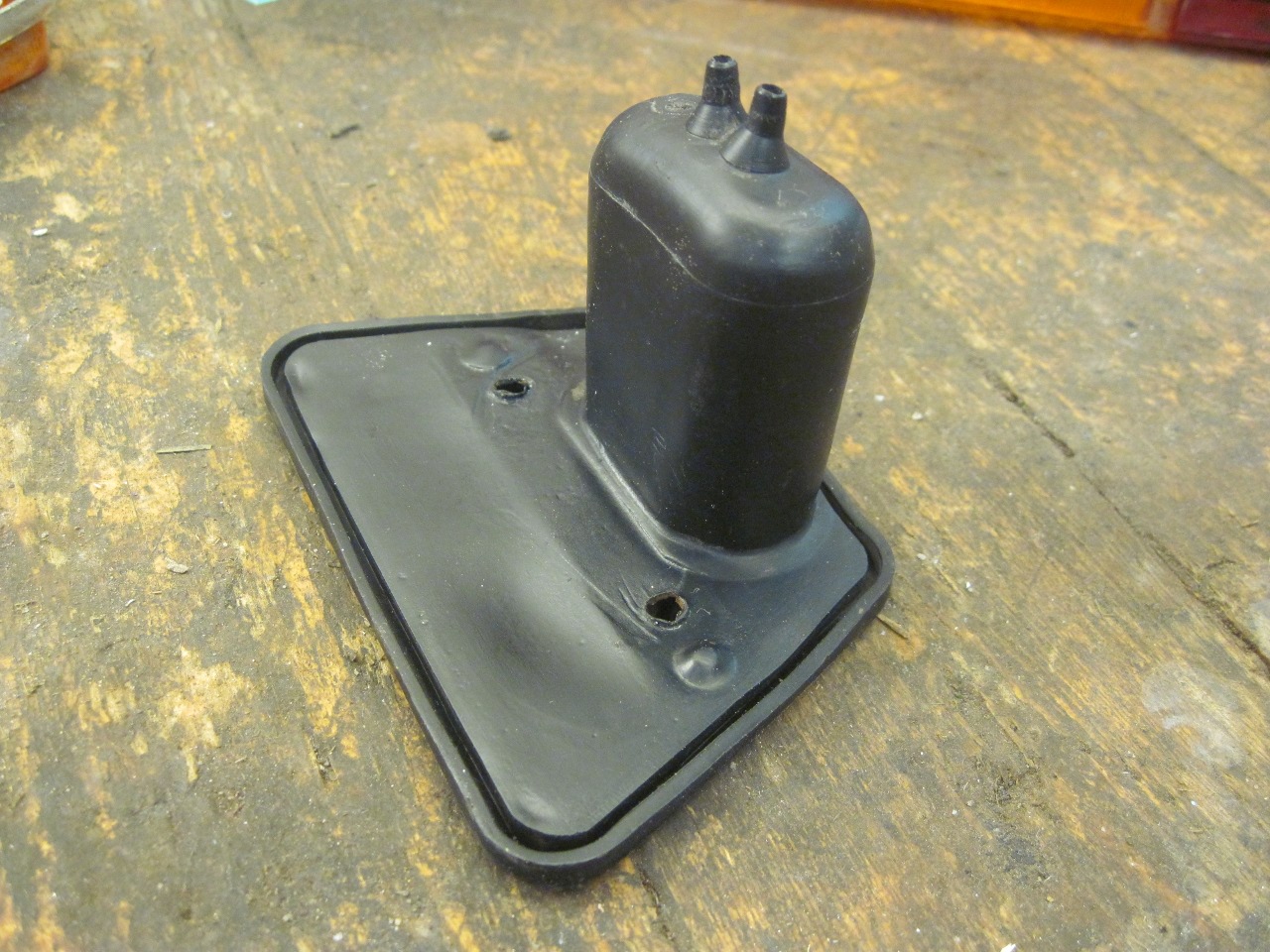
I
continue to be amazed by the durability of some of the old British
rubber parts. Cleaned up, the rubber boots look better than some
new rubber parts I've bought.
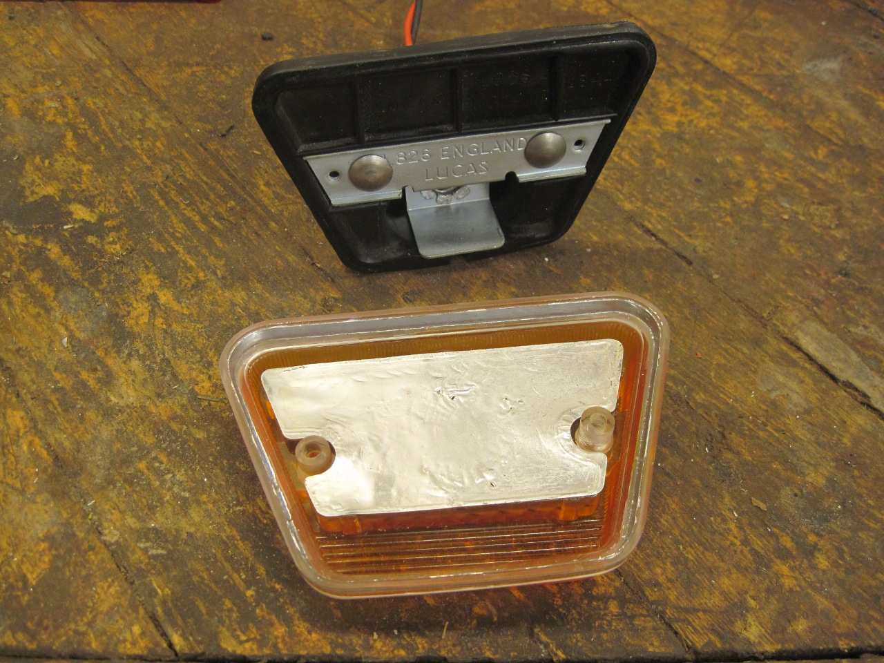
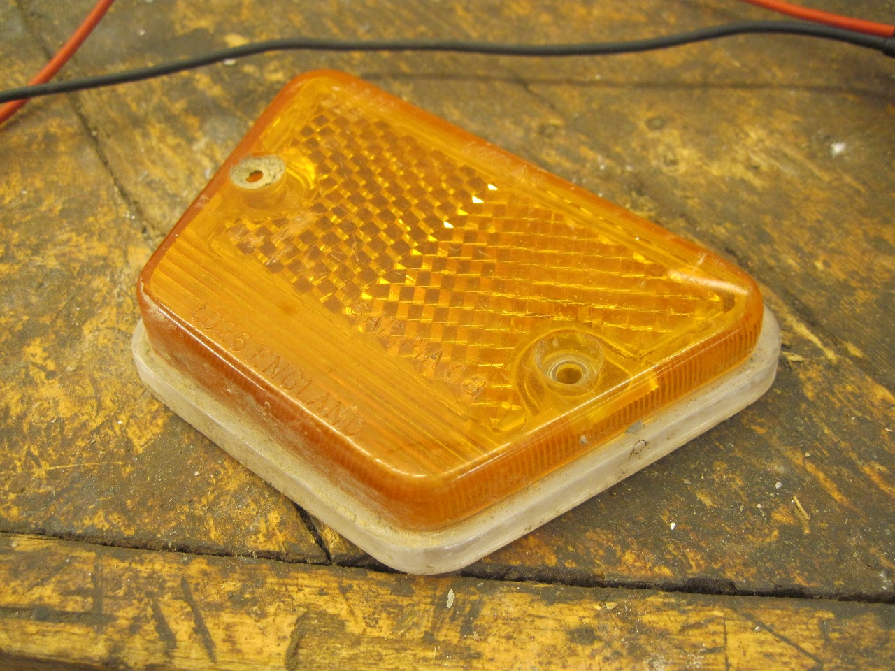
The
US markers had an internal reflector, and "chrome" on the perimeter of
the lens, both apparently not included on the European models. My
reflectors were detached and roaming free inside the lens, so I had to
glue them back in place.
The
chrome on lens surround was in pretty bad shape, so I scraped it
all off. I didn't waste much time looking for paint, but fell
back to my newfound technique of metal leaf that I used on the tail
light reflector.
I'll be proud to put these back on the car someday.
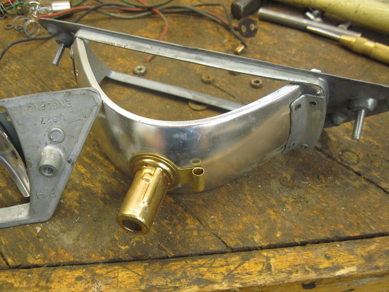
Front Signal Lights
The
front signal lights are also pretty simple. A cast frame holds an
aluminum reflector and lamp socket. A rubber boot covers the
backside and seals against a lens at the front.
Ther
was a little sheet metal work to do on one of the reflectors.
There was no body damage in this area, so I wonder if it was
installed this way.
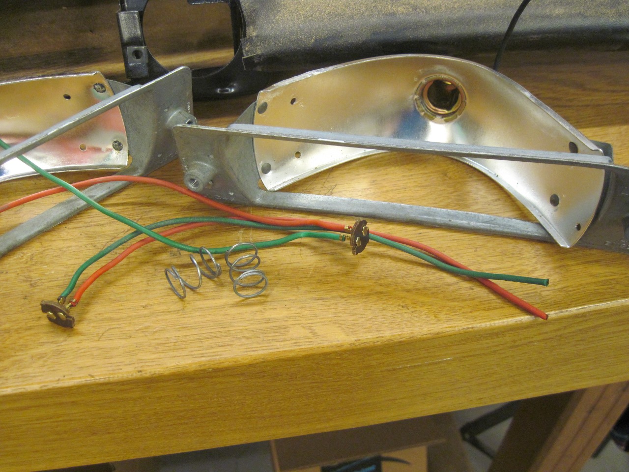
Unlike
most of the other lights on the car, the mounting studs here didn't
break off on disassembly. They were pretty rusty, though, so they
just got derusted and replated.
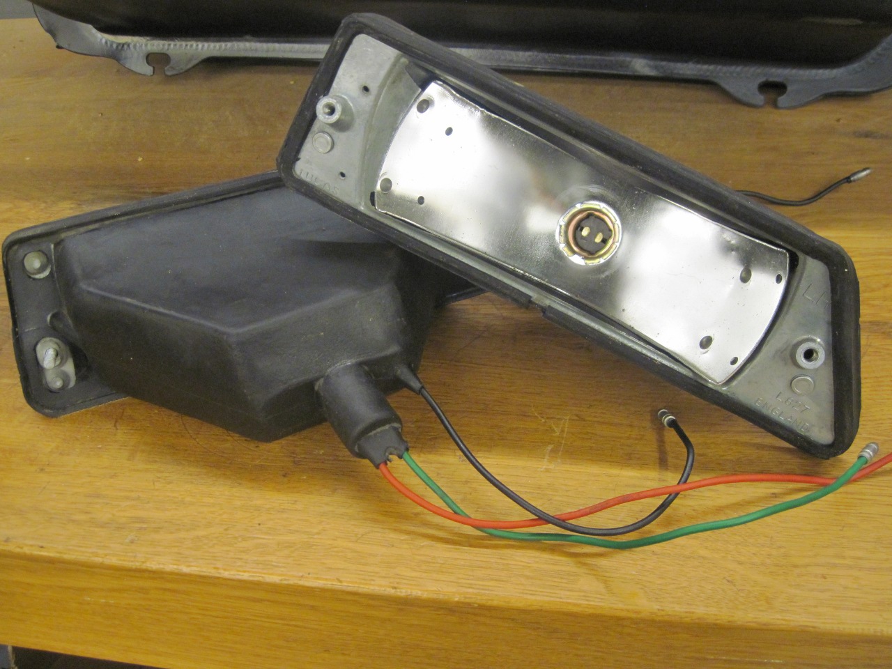
Happily, the these fixtures also have a real ground wire connector.
Took the sockets apart for cleaning.
The
rubber boots were in wonderful shape. The only defect was a small
tear--looked more like a cut, acutally--in the side of one of them.
I fixed it easily with a patch from a bycycle tube repair
kit.
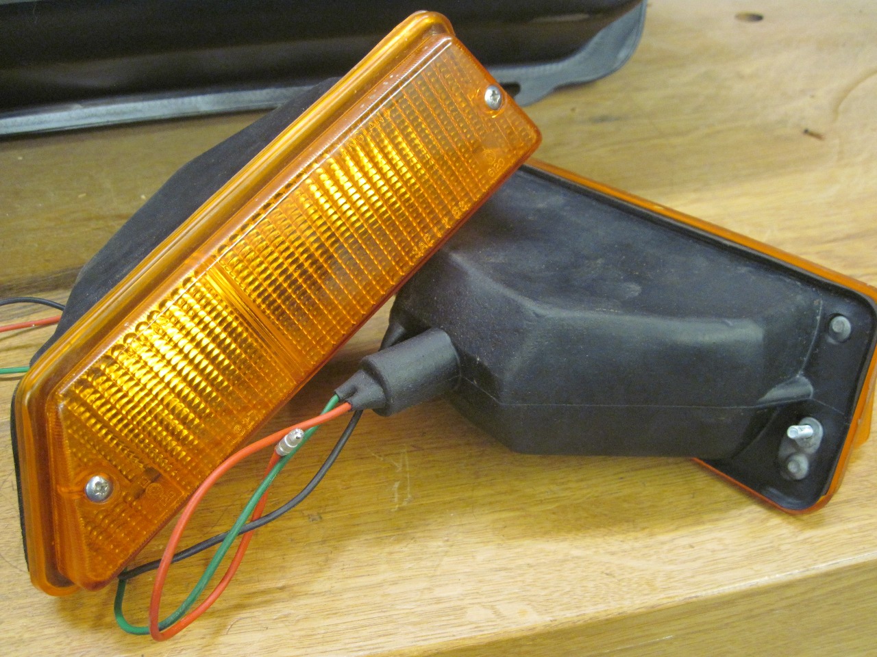
Ready to go...
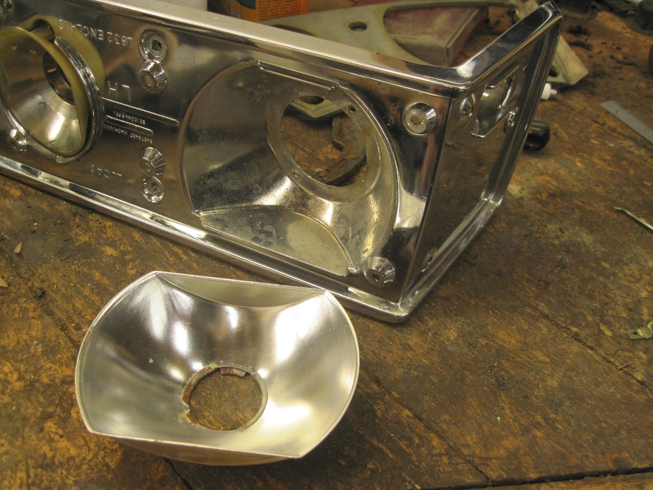
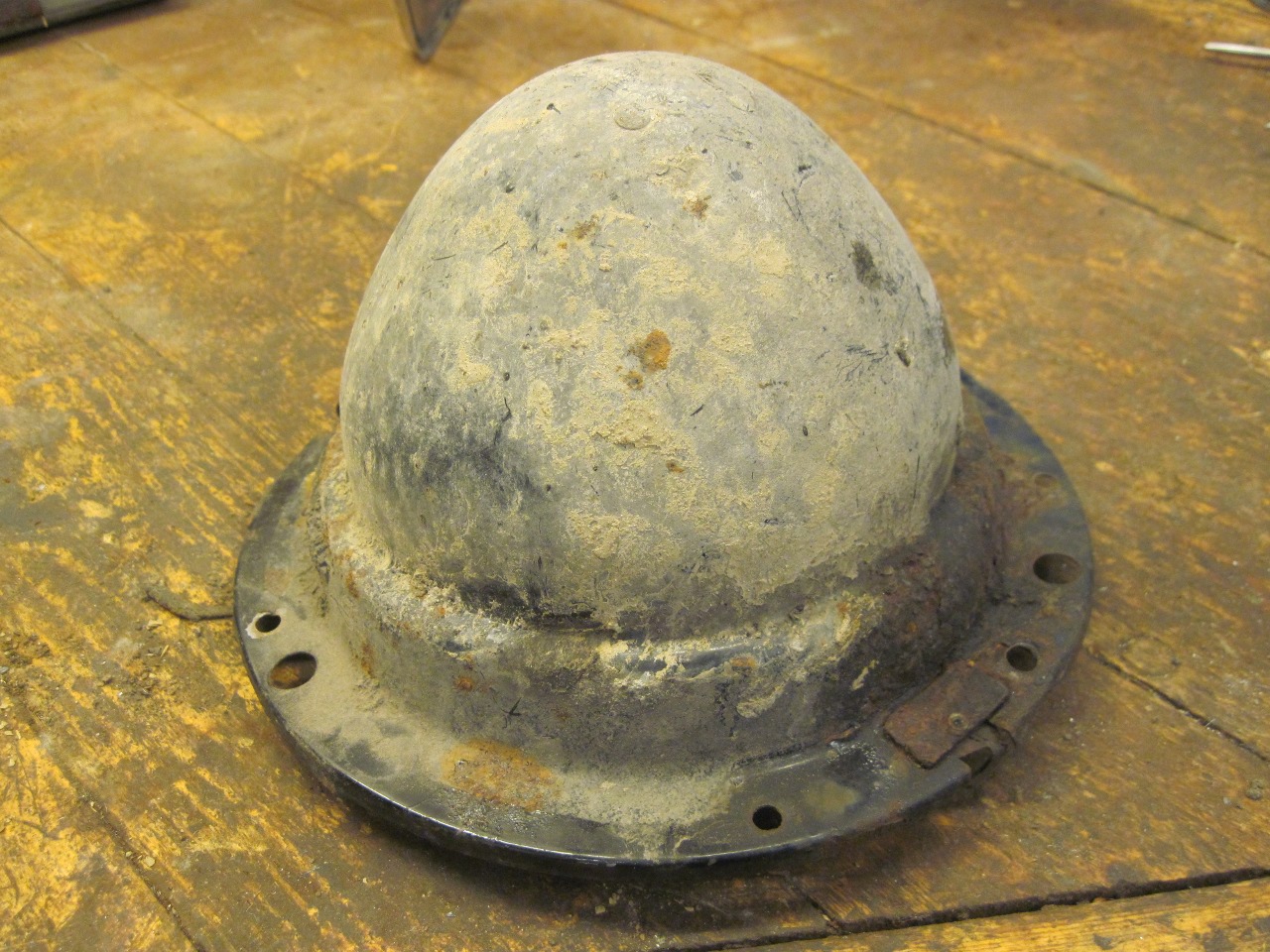
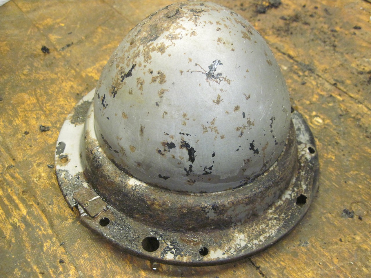
Headlights
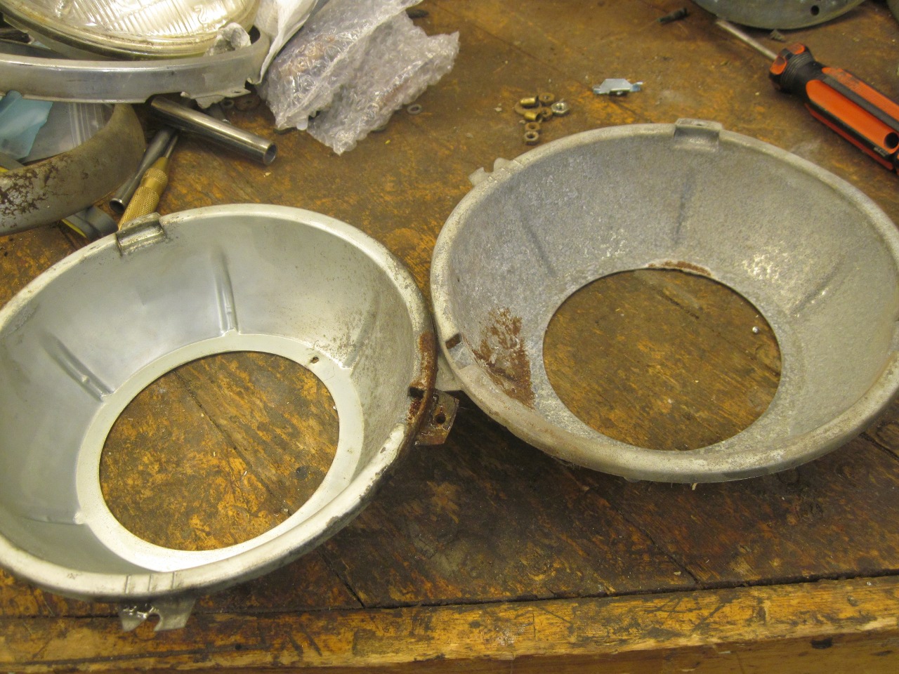
Well,
I made a valiant attempt to save my headlight buckets, but when all the
paint and rust were removed, there were just too many holes that
shouldn't be there. Considering the cost of new ones, I just
ordered a pair.
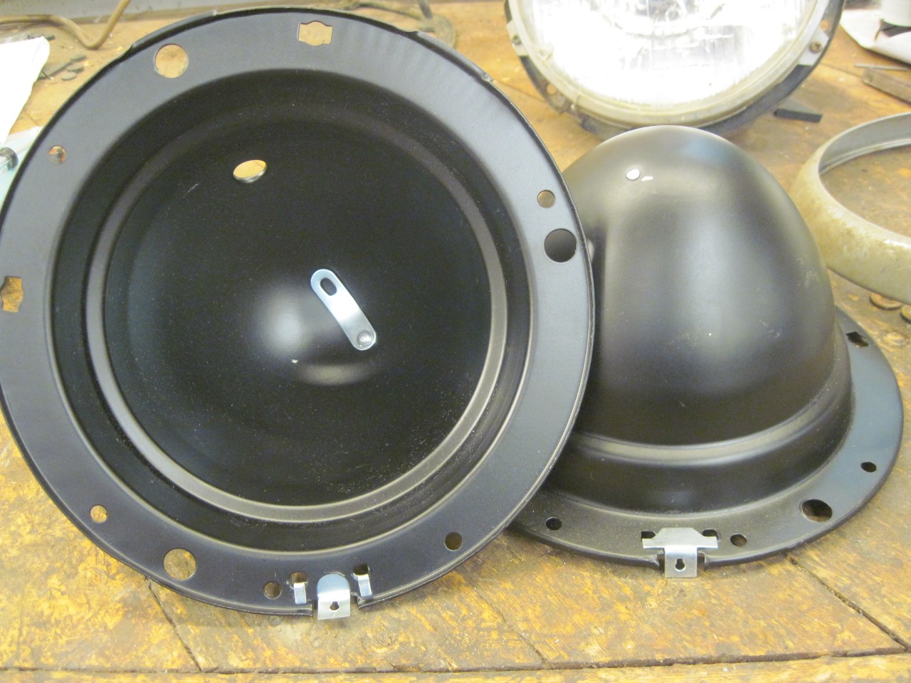
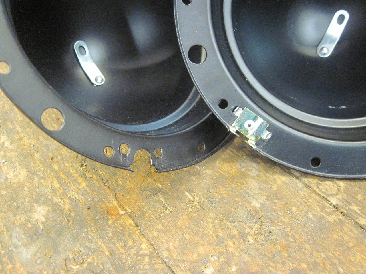
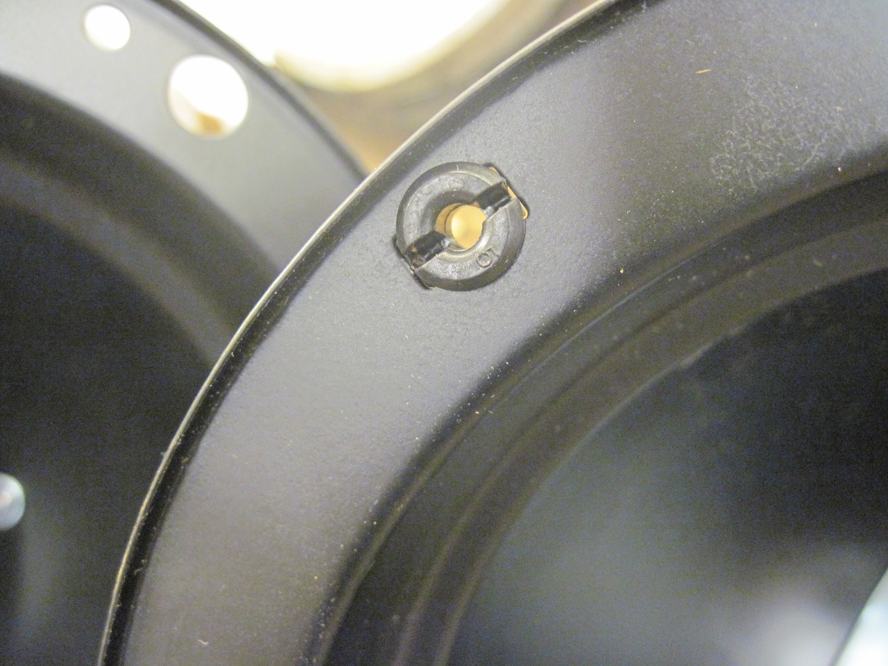
These
buckets come without the proper spring clip to hold the chrome finish
ring. The little fastener piece has to be removed and the correct
clip riveted on in its place.
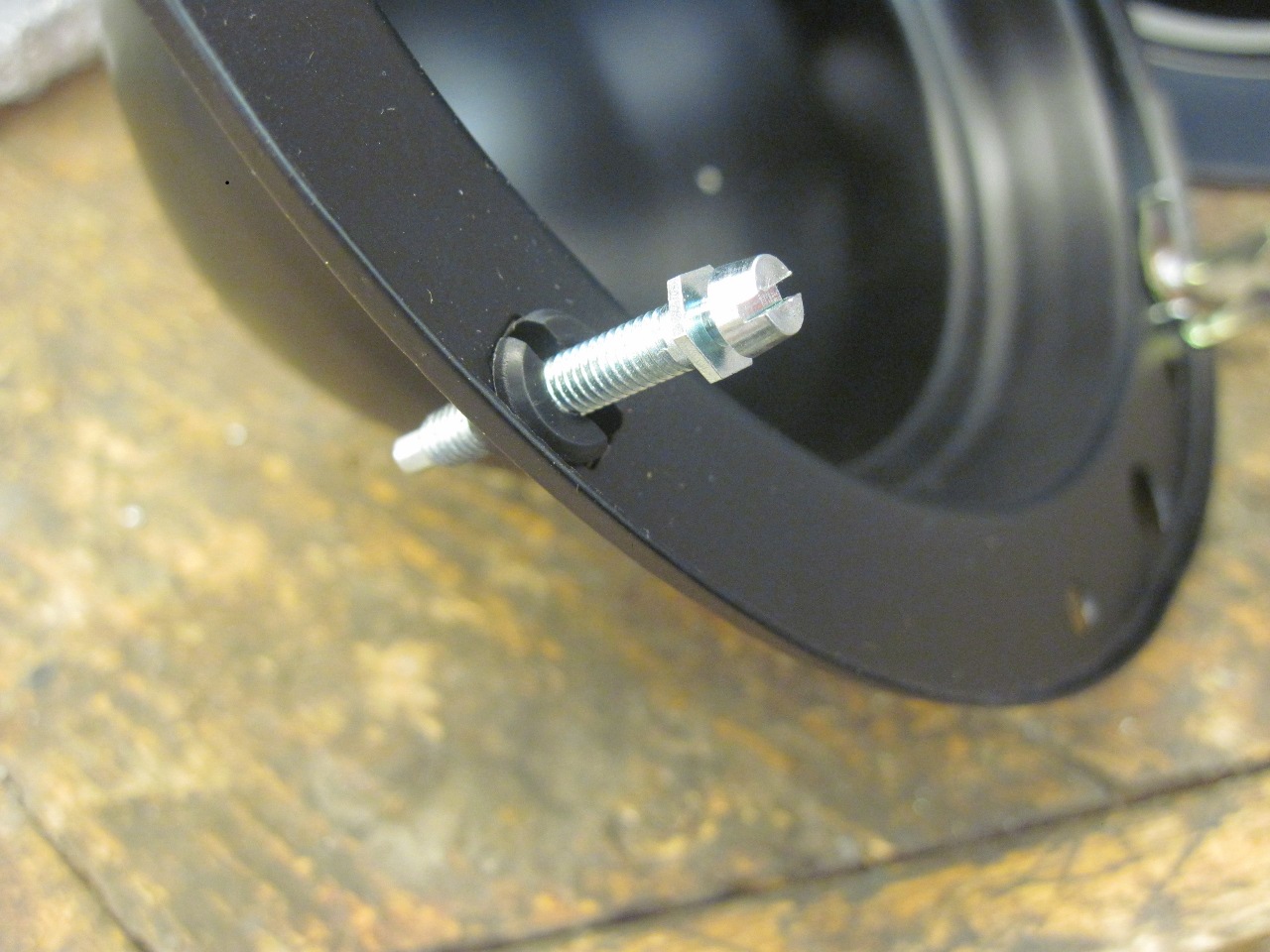
Then the headlight adjusting screws have to be installed with their little plastic grommets.
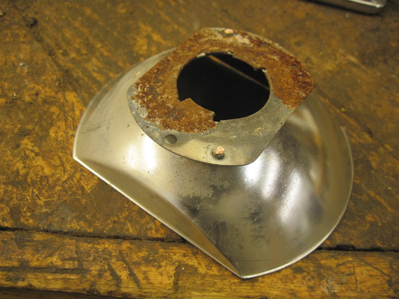
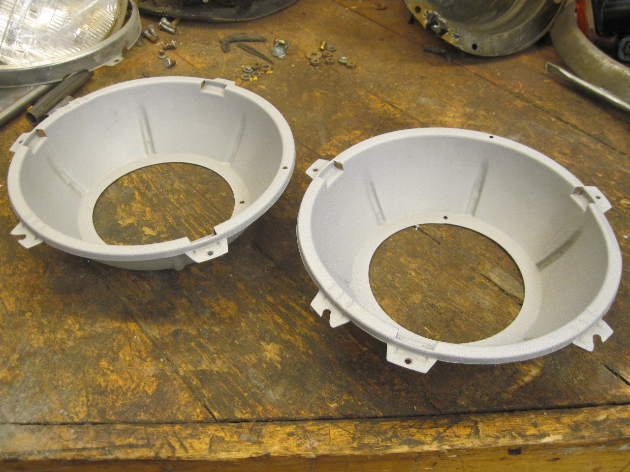
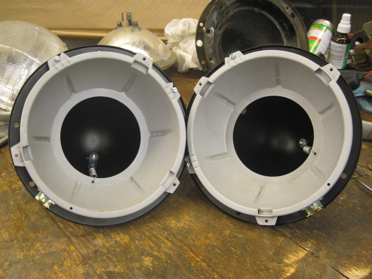
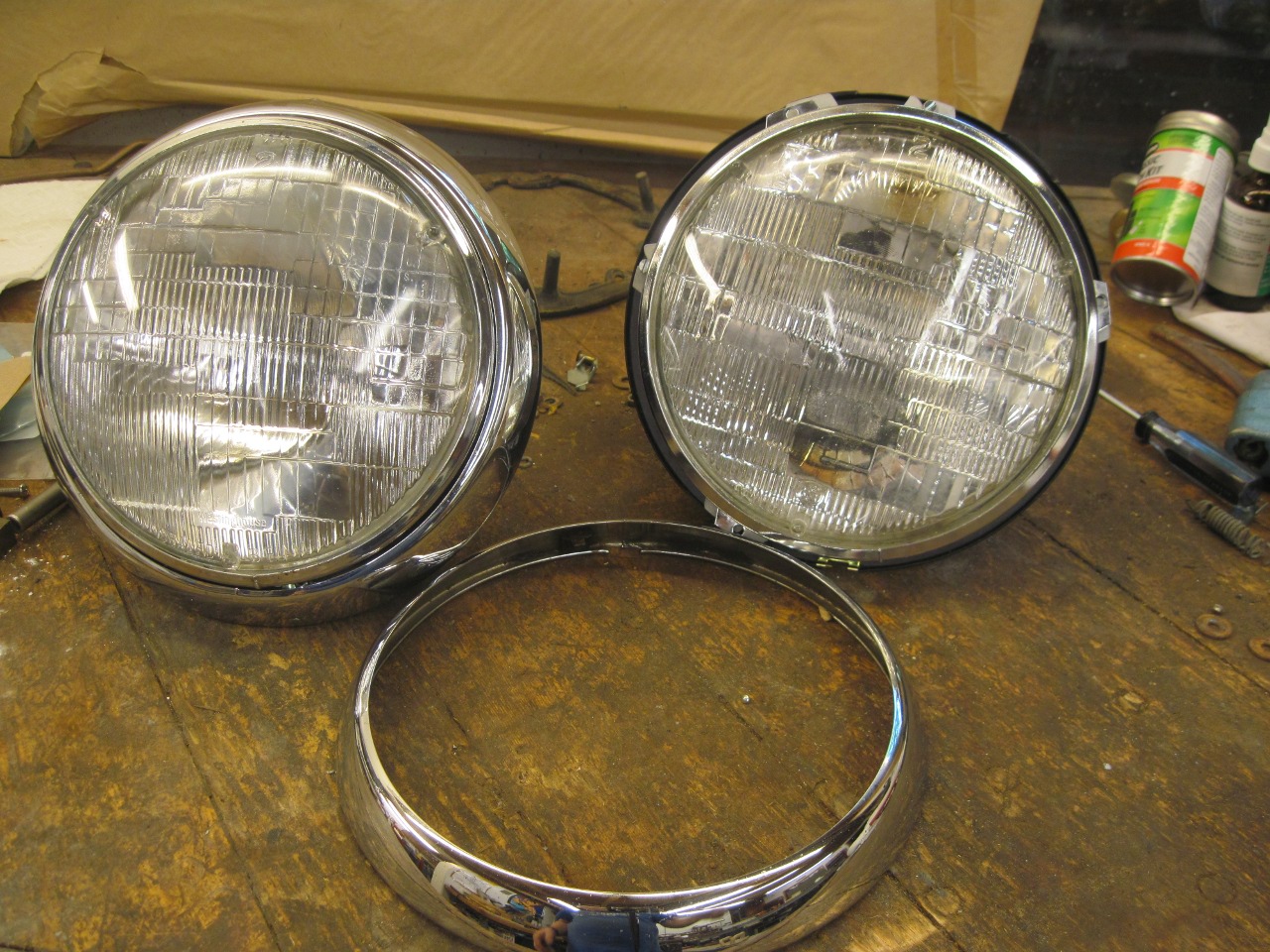
The
inner rims which cradle the sealed beam unit from the back side showed
quite a bit of corrosion. It's more than just cosmetic.
Rust indicates that the zinc plating is breached, and the
deterioration will only get worse. These pieces are a little
large for my small plating tank, so I powder coated them in a matte
silver.
The inner rim attaches to the adjusting screws, and is held in place by a spring hooked at the bottom of the bucket.
The wiring harnesses to the sockets were a mess. There
were splices in the buckets, and the insulation on the wires was chafed
in a few places. I considered trying to find the wire terminals
that fit inside the connector housing and just make new pigtails, ut in
the end, I just ordered new headlight pigtails.
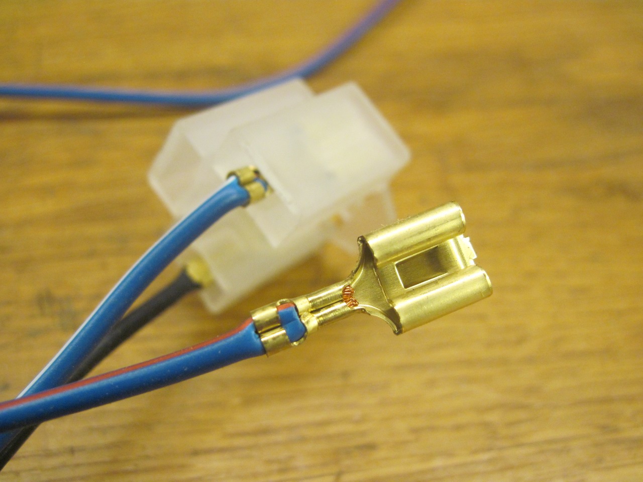
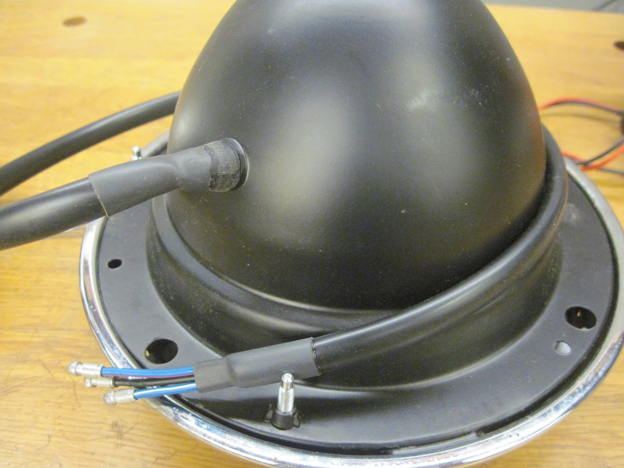
The
new pigtails were mostly OK. They appeared to use good quality
terminals well crimped. I added some heatshrink for a little
extra protection.
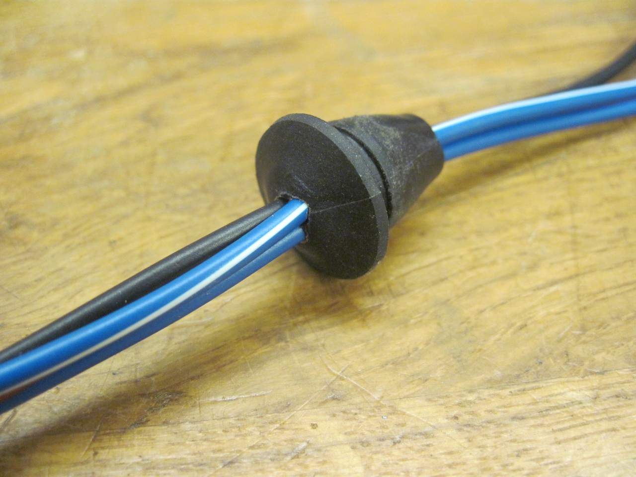
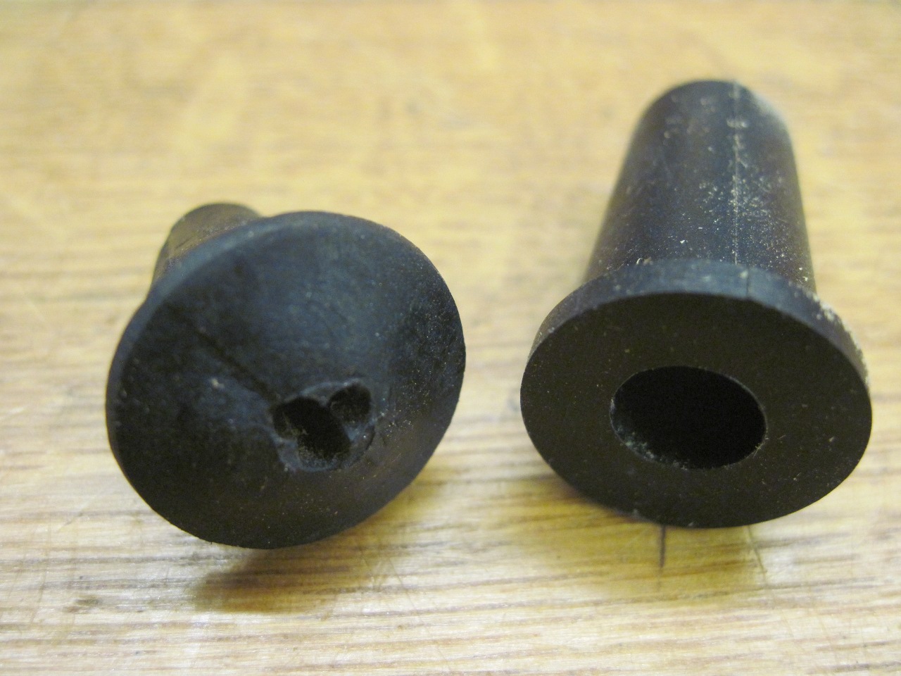
One
small disappointment was the grommet that fits in the bucket. The
original grommet appeared to be molded on the wires while the
replacement was just a rubber sleeve that was a loose fit over the
wires. If the grommet was intended to seal the bucket or provide
strain relief, the new grommet was going to fail.
I
removed the grommet from one of my original pigtails and since it was
still in very good condition, I slid it onto the new pigtail's wires
(after removing the soldered bullet termoinals). My other
original grommet was missing, so I had to appeal to a generous members
of one of the popular TR6 forums. I had one on a few days.
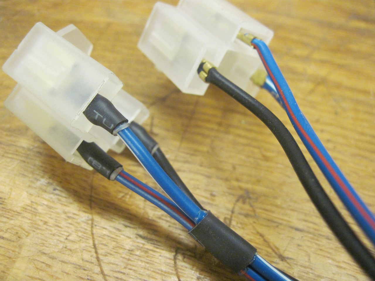
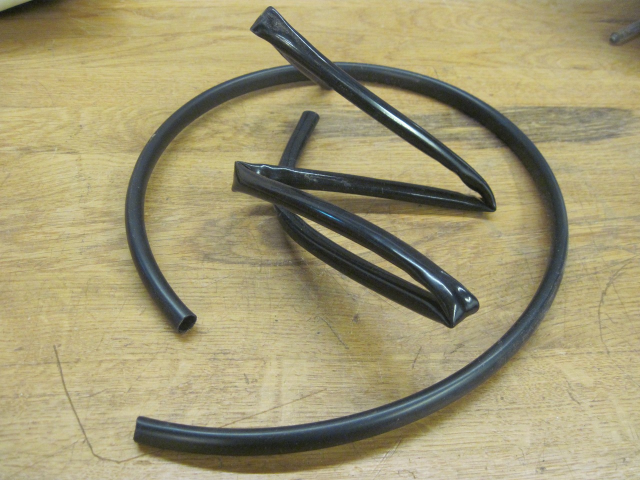
While I had the pigtail apart, I decided to replace the rather cheesy looking sleeving with some heavier stuff I had on hand.
A little more heatshring to seal things up, and the pigtails were installed.
I'll
be considering an LED conversion for these headlights, so this is as
far as I'll go, but these are pretty much ready to install.
All
this lighting work has been a background task for the last month or
two. It was finicky, but enjoyable. There wasn't much cost
except for the LED lamps.