To other TR6 pages
December 2, 2013
Fuel Pump
The TR6 used a pretty standard mechanical diaphragm fuel pump driven from an eccentric on the camshaft.
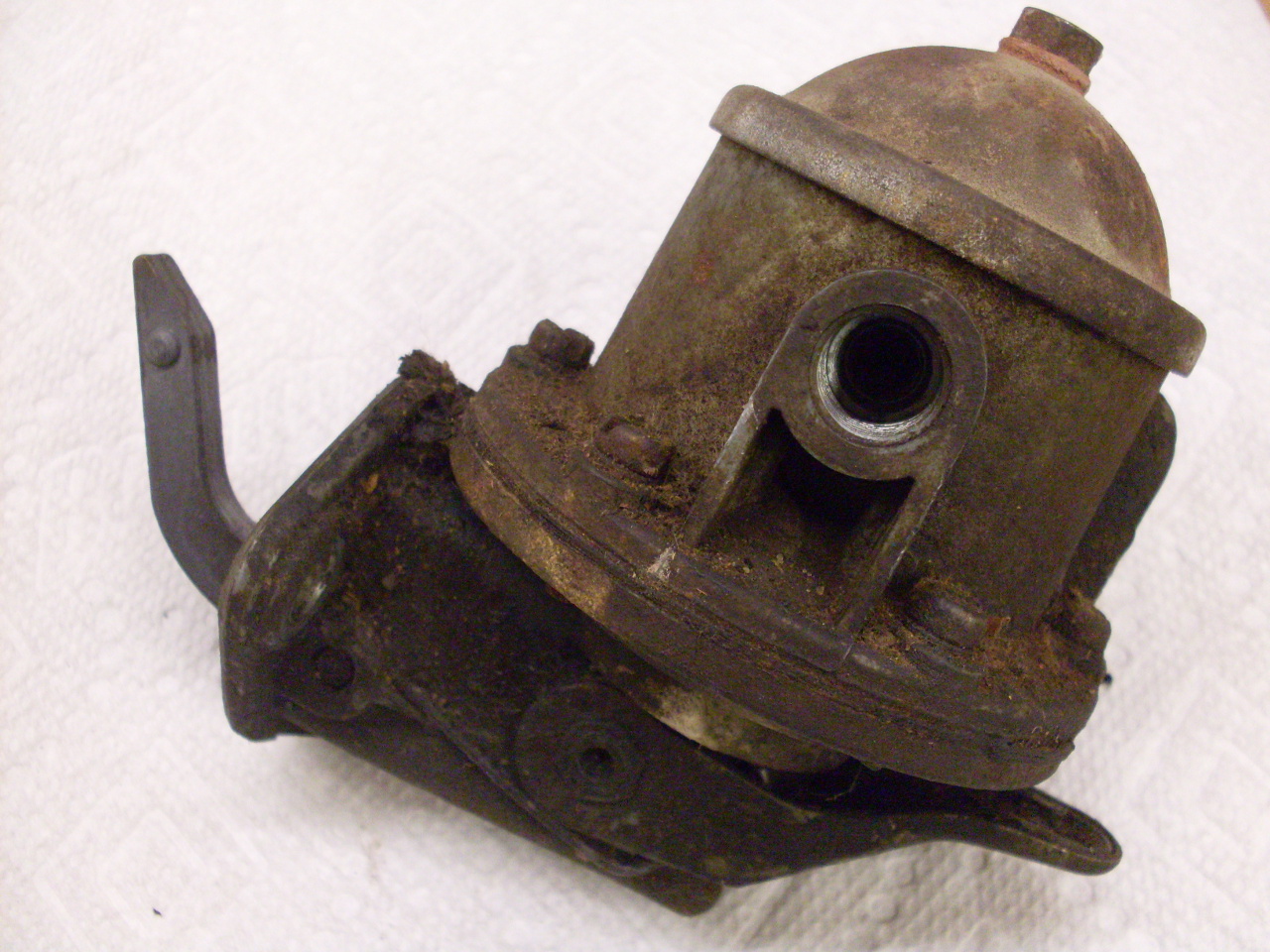
As
the diaphragm moves down, it pulls fuel through a check valve from
the fuel supply line into a sediment chamber, through a fine screen,
and into the cavity above the diaphragm, while on the upstroke,
it forces fuel through the other check valve to the pump outlet.
The two opposing check valves are held in place with a retainer.
After over 30 years of storage, this pump chamber still had liquid fuel residue in it.

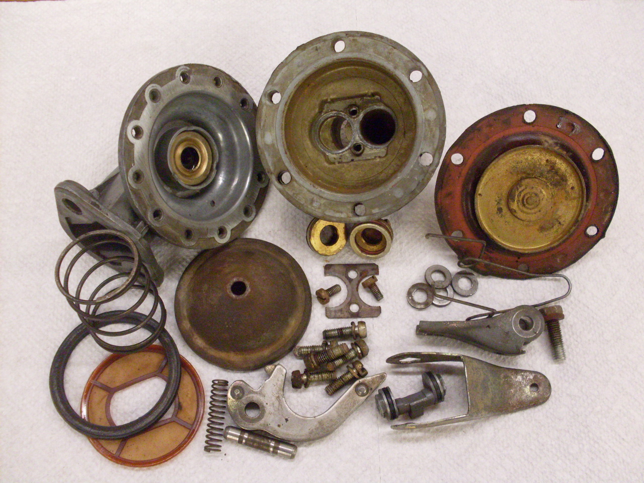
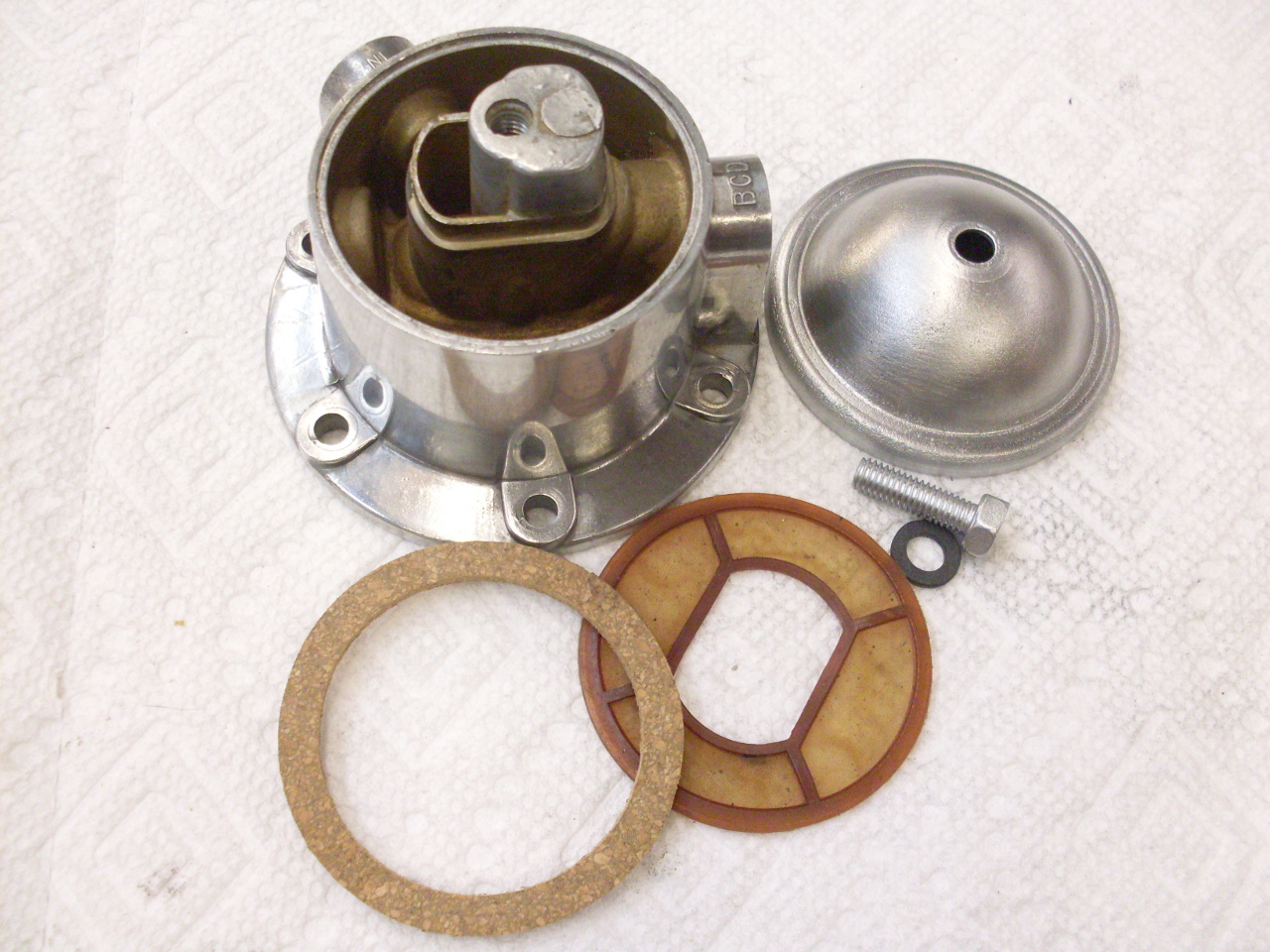
Here
are all the parts of the fuel pump. Rebuild kits are available
that include mostly "soft" parts, but they seem to be pretty generic,
so there are extra parts in the kits, and in the case of this pump, a
couple missing.
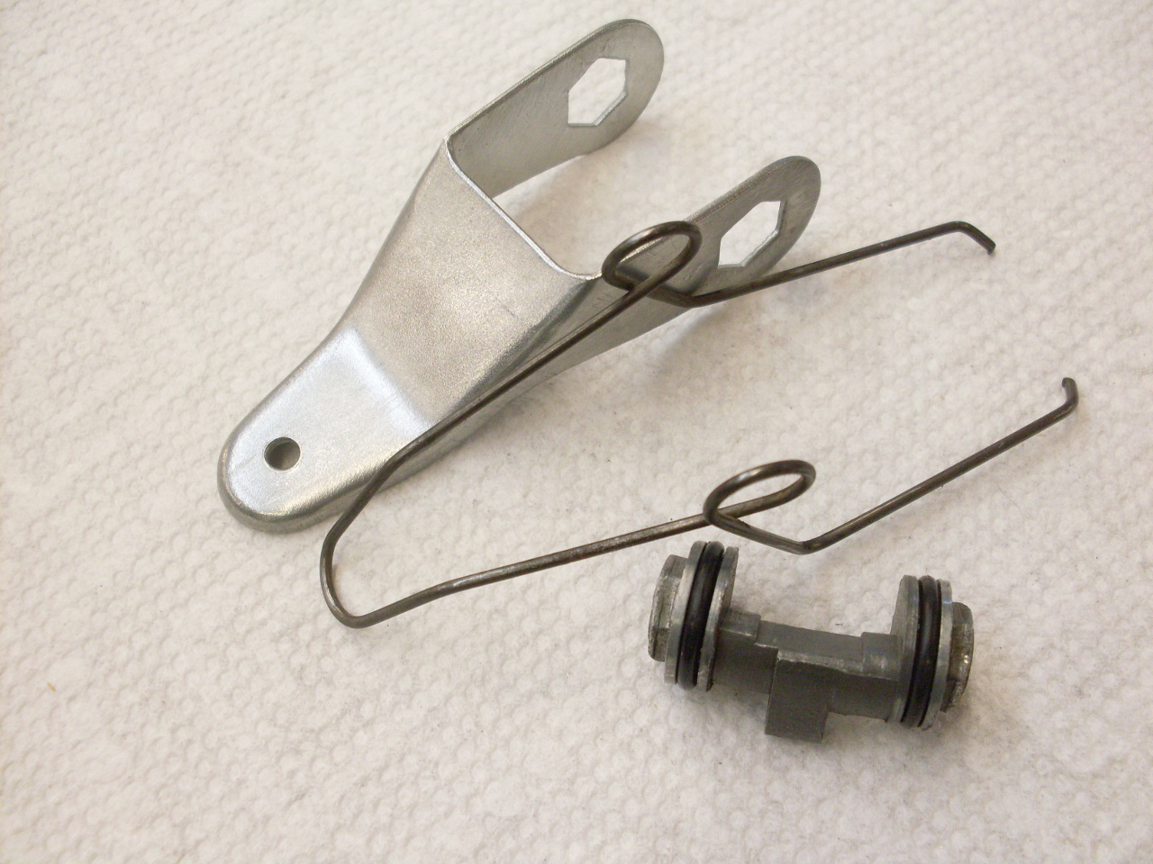
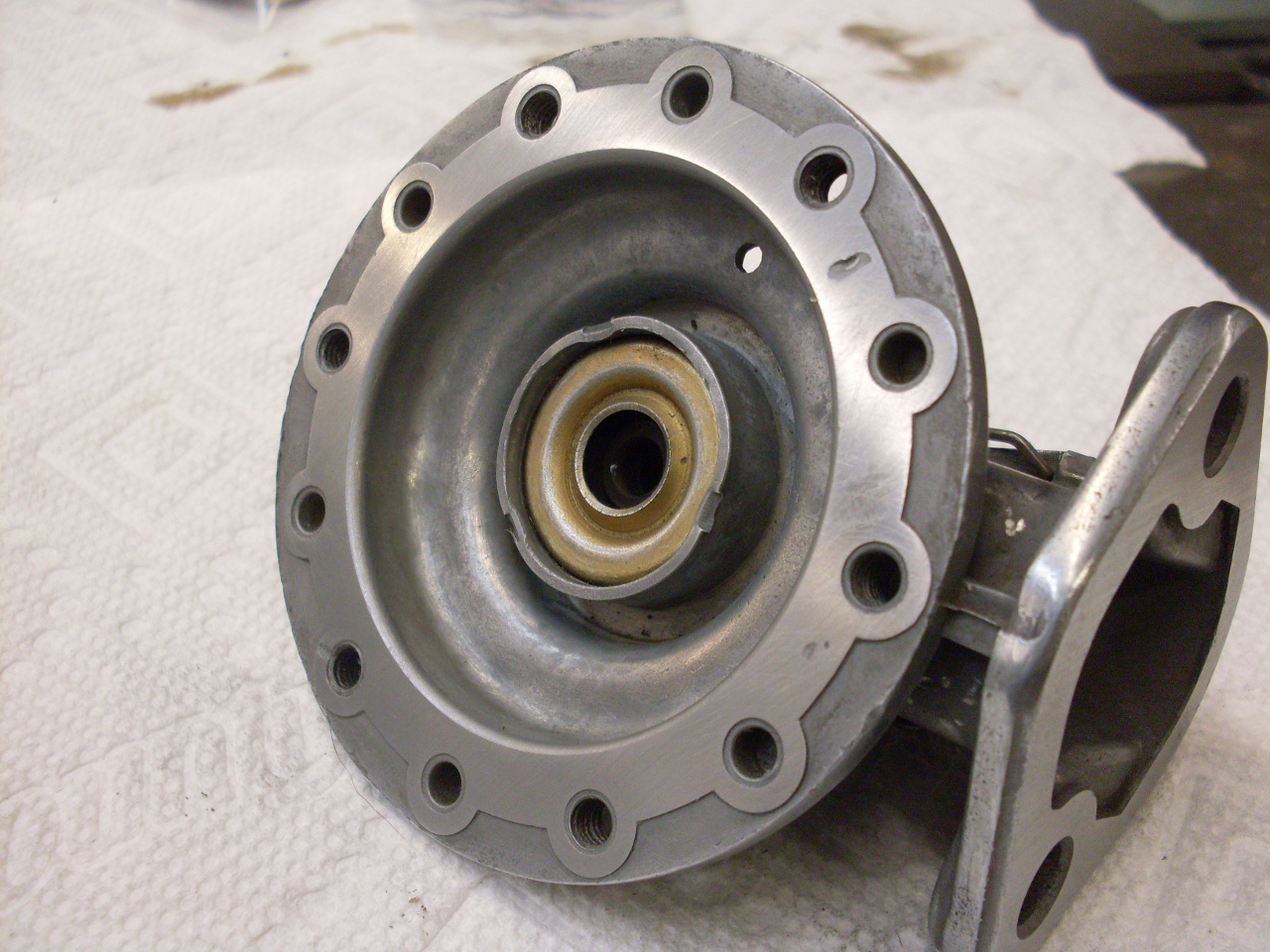
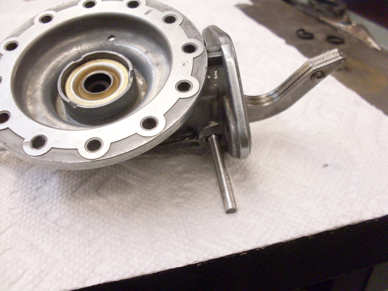
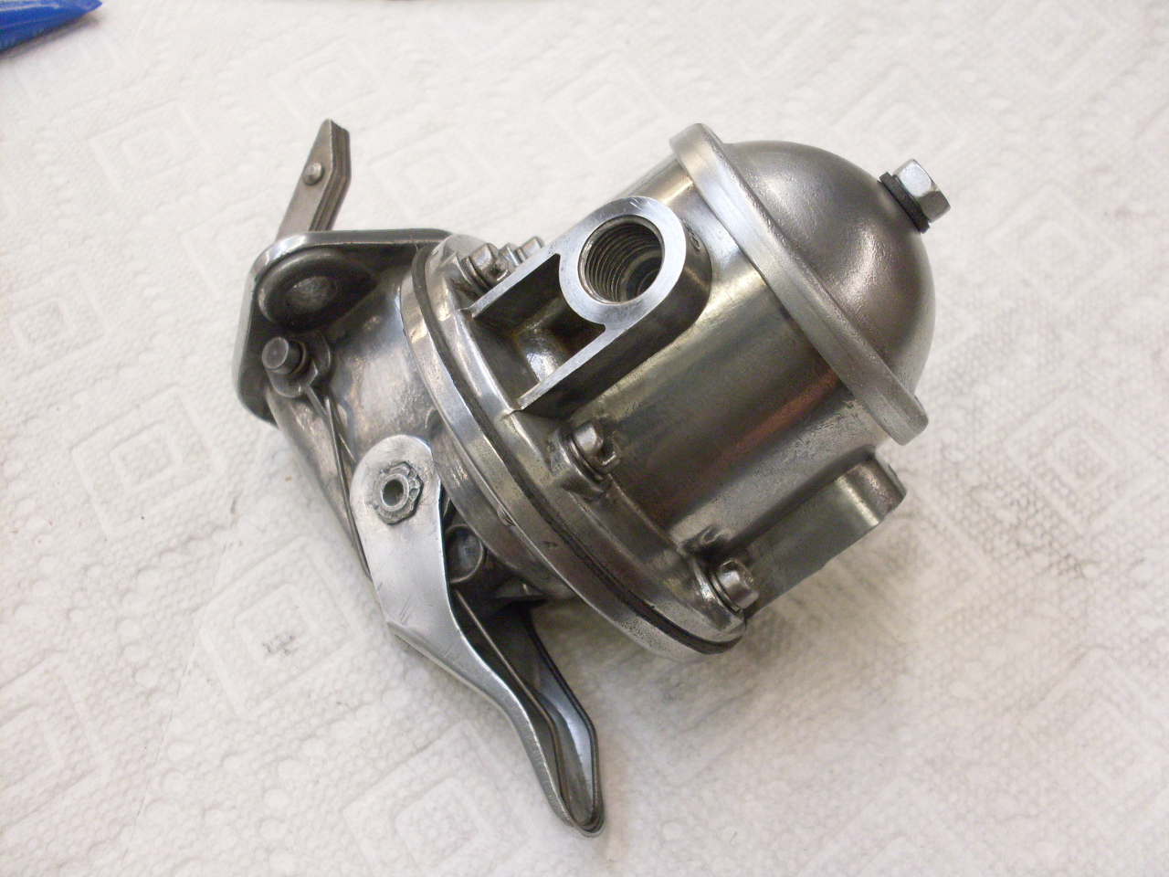
This
pump has a spring loaded lever on the underside so that the diaphram
can be moved manually. I guess this could be used to "prime" a
carb by filling its float bowl, but I'm not sure what the real intent
was. At any rate, the kit didn't include the O rings for the
lever shaft, and made no mention of it in the instructions. The
lever is fixed to a little cam shaft by hexagonal protrusions on the
ends of the shaft that are peened over slightly to lock the lever in
place. There is an O ring on either side of the cam shaft where
it passes through the pump body, When the lever is raised, the
cam presses on an internal link that moves the diaphragm. The O
rings were not in the rebuild kit, and had to be bought locally.
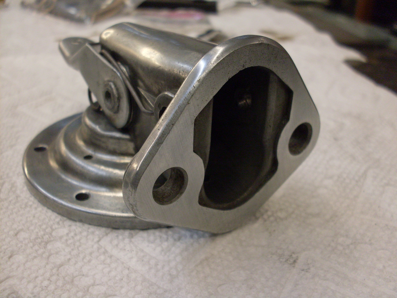
The second picture shows the lever after zinc plating.

Before I started to put everything back together, I linished all the mating surfaces to see that they were flat.
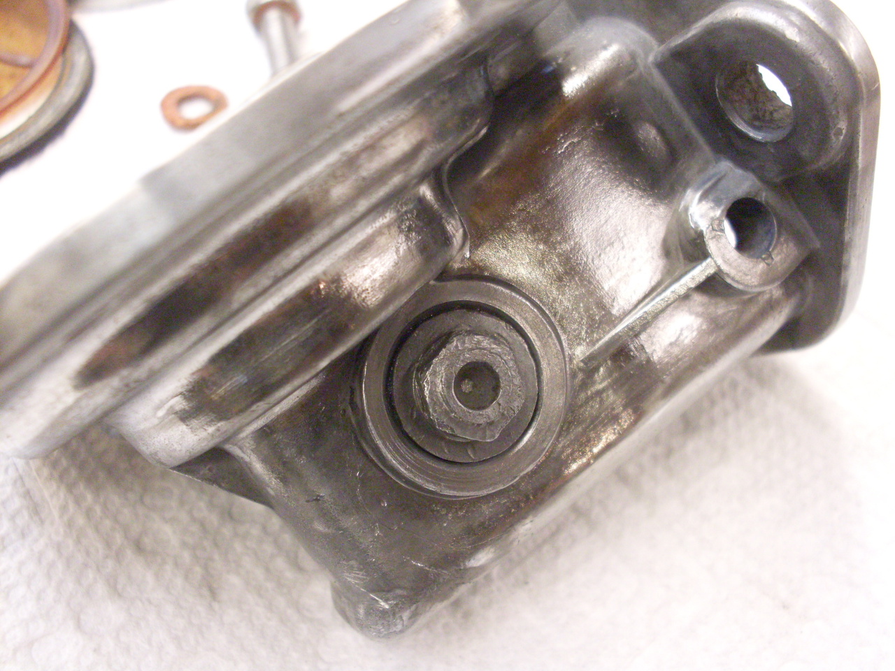
There
are several interconnected linkage parts deep within the bottom part of
the body. The instructions suggest using an "assembly pin" to
help get everything together. It is just a pin that goes place of
the pivot pin, but has one end a smaller diameter than the pivot pin.
This end holds all the parts in place, but allows extra movement
to get the rocker arm spring and diaphragm installed. The
assembly pin is then shifted to the thicker end so that it locates
everything, and so that the real pivot pin can be driven in.
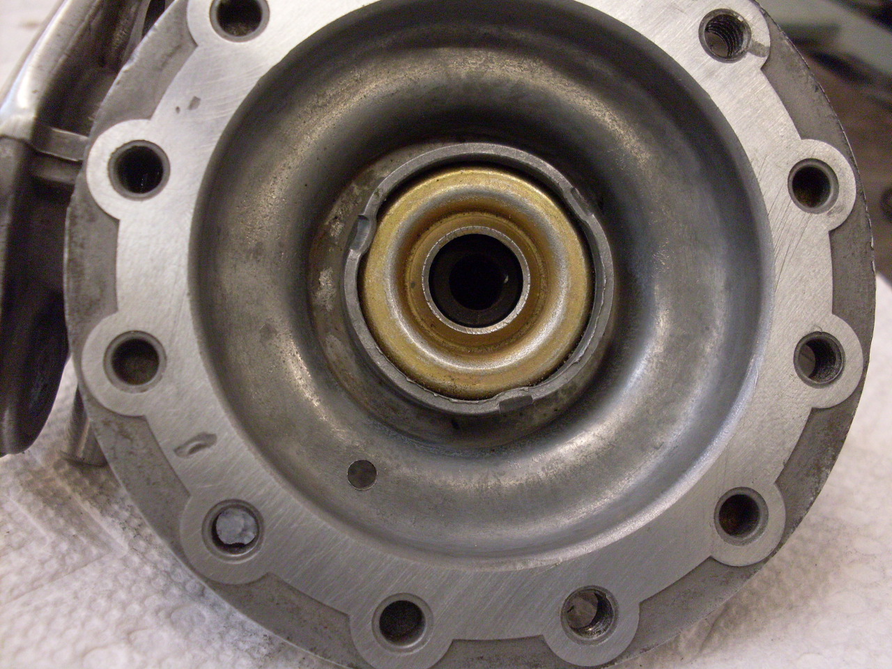
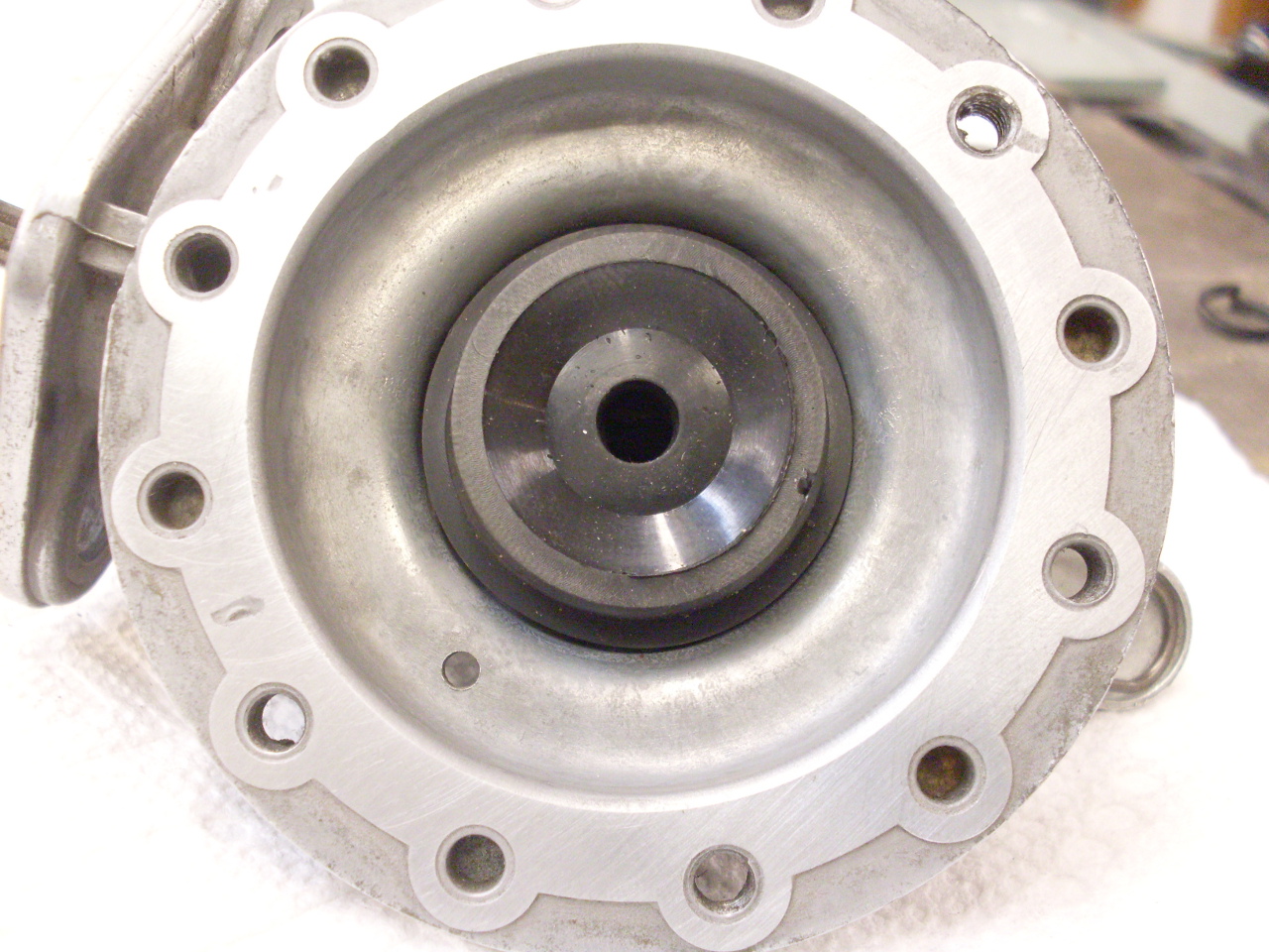
There
is an oil seal staked in the bottom body casting, which rides on
the diaphragm shaft and seals off the part of the pump that opens to
the engine crank case. Though I wouldn't have a problem unstaking
it, the seal is not part of the rebuild kit. Instead, the kit
contains a new seal "cap" that fits over the old seal housing,
and under the diaphragm spring.
Next,
the diaphragm itself. It's a little tricky trying to get the
end of the diaphragm shaft to engage properly with the actuating
linkage without being able to see it.

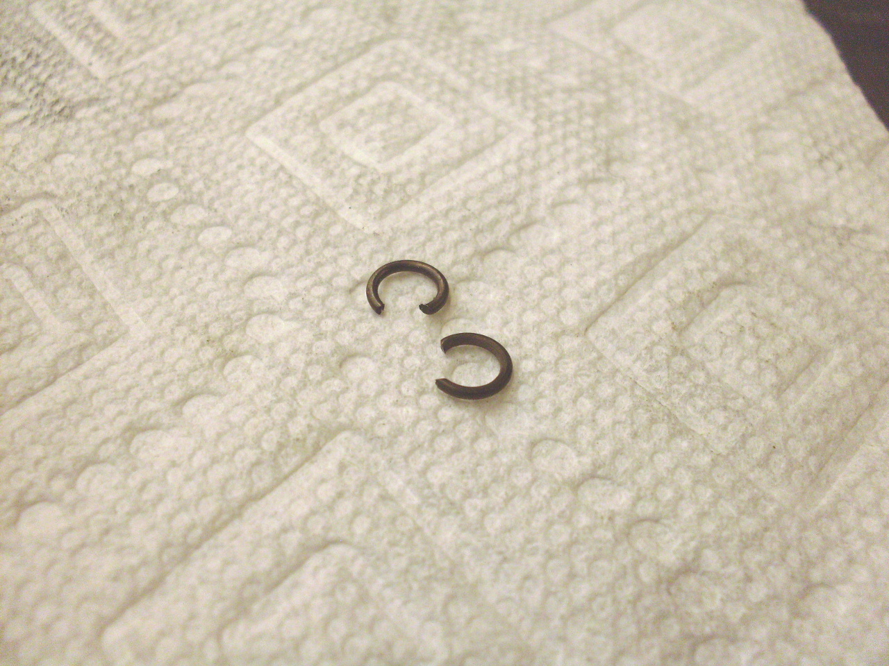
These
little devices are someone's idea of a cruel joke. They go into
little grooves in the ends of the rocker arm pivot shaft. I put
my odds at about even for having at least one of them launch itself to
some unknown hidden place in the shop. Surprizingly, I finally
got both of them in place with only a little swearing.
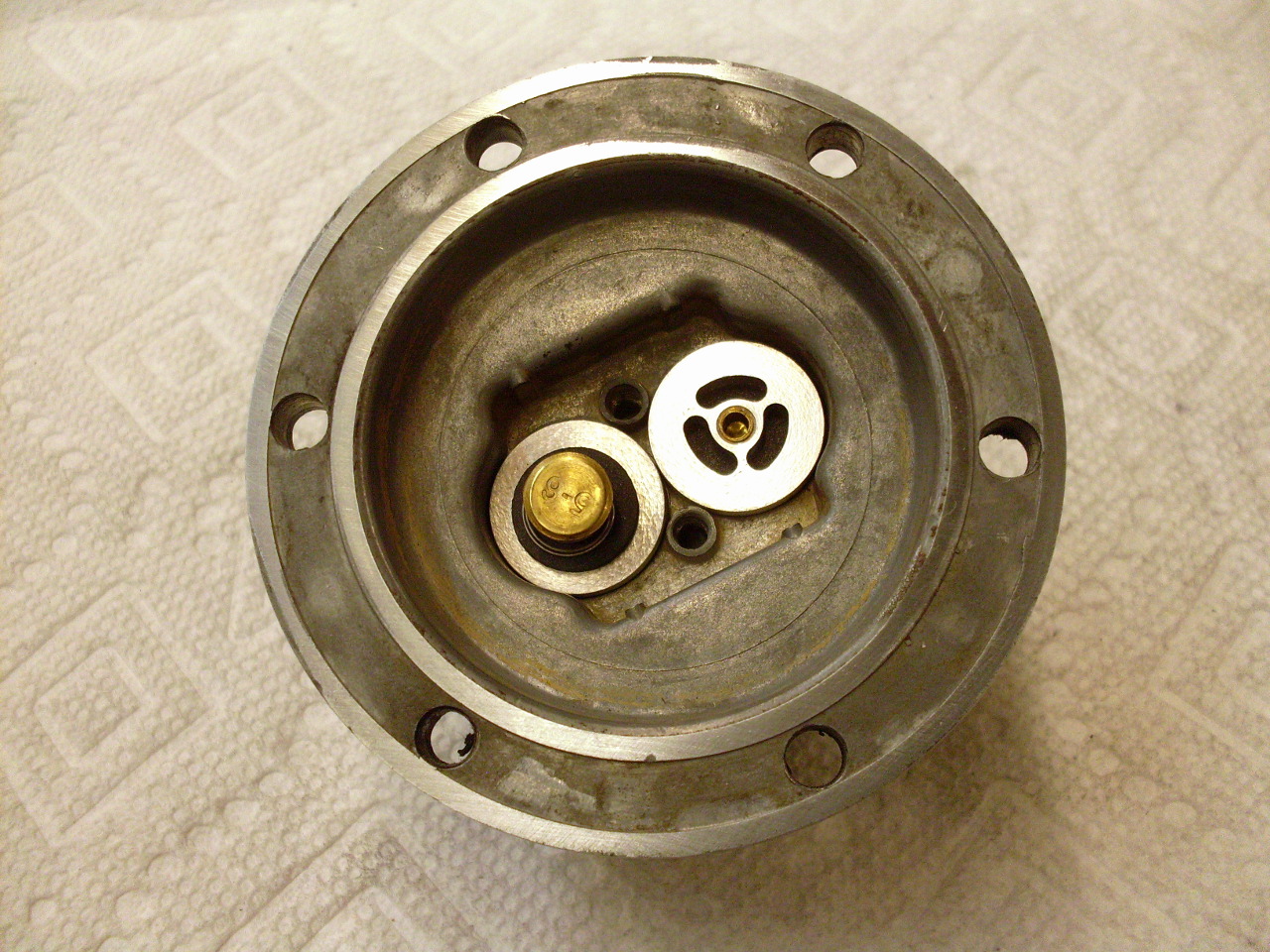
The
new check valves. Literal interpretation of the instructions
would have had me install them backwards. The text must have been
written for a different valve design. This is a case of reading
between the lines to determine what the instructions intend, not what
they say. A little Locktite buys some insurance.
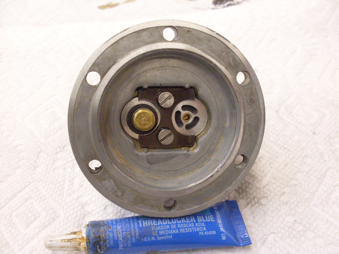
The
top part of the body gets a screen and gasket under the domed cap.
The cap was pretty rusty, so I zinc plated it and its fastening
nut.
Finished pump on the shelf until it's needed.
Comments to: elhollin1@yahoo.com
To other TR6 pages