To my other TR6 pages
November 18, 2015
Brake Servo
All
TR6 cars had power assist brakes. The power comes from engine
vacuum collected from the intake manifold and stored in a reservoir in
the brake servo unit. The servo unit fits between the brake pedal
and the brake master cylinder so that it can both sense pedal position
and also augment the force applied to the master cylinder.
The
servo unit on a TR6 is another one of those devices usually considered
not to be a DIY item. While these kinds of warnings amuse me, the
servo is a little different. Even if a determined person manages
to get inside the unit, none of the internal parts appear to be
available from retail suppliers. There are commercial outfits who
will rebuild the servos, so they apparently have the parts custom made
for them. Before laying a hand on my servo, I contacted one of
these rebuilders about the possibility of buying internal parts,
particularly the main diaphram. They declined to sell me
anything, citing "liability concerns", which doesn't ring true to me.
It seems to me that rebuilding or otherwise supplying entire
brake servos would imply as much or more liability risk.
At any
rate, I decided to forge ahead. If I got to the point where the
servo would be junk without some new innards, I could still just bag
everything up and send it off to a rebuilder. Even if it came to
that, I could still powder coat the cases myself and save a little coin.
There is a wonderful resource on the Web for anyone considering opening a servo. The technical pages at buckeyetriumphs.org
are a goldmine of information for many aspects of the TR6, including
the servo. I'm indebted to the folks at Buckeye for providing
this valuable asset.
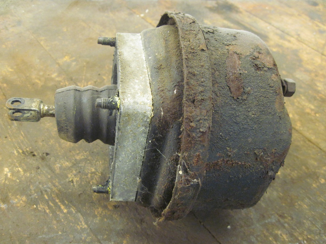
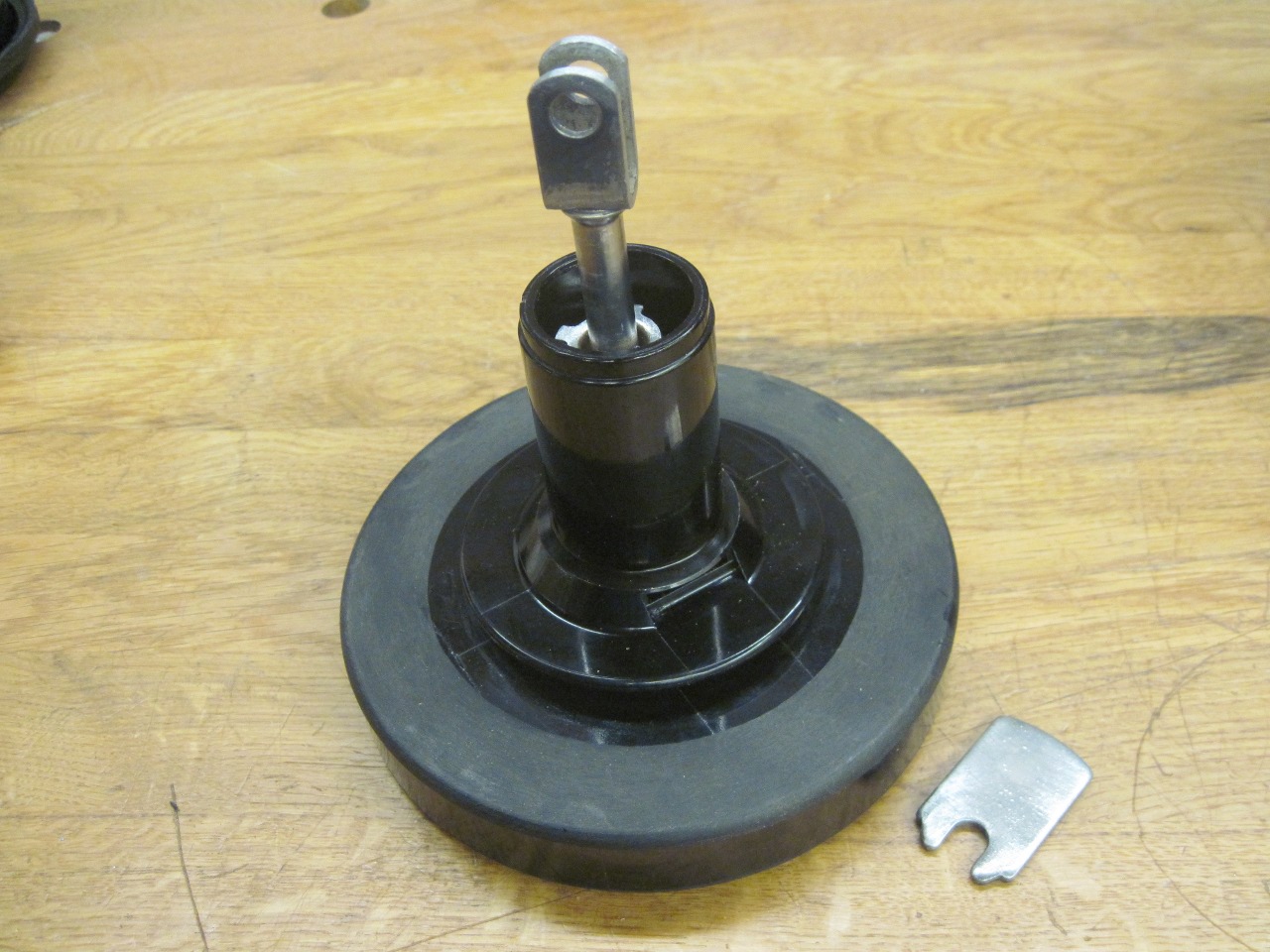
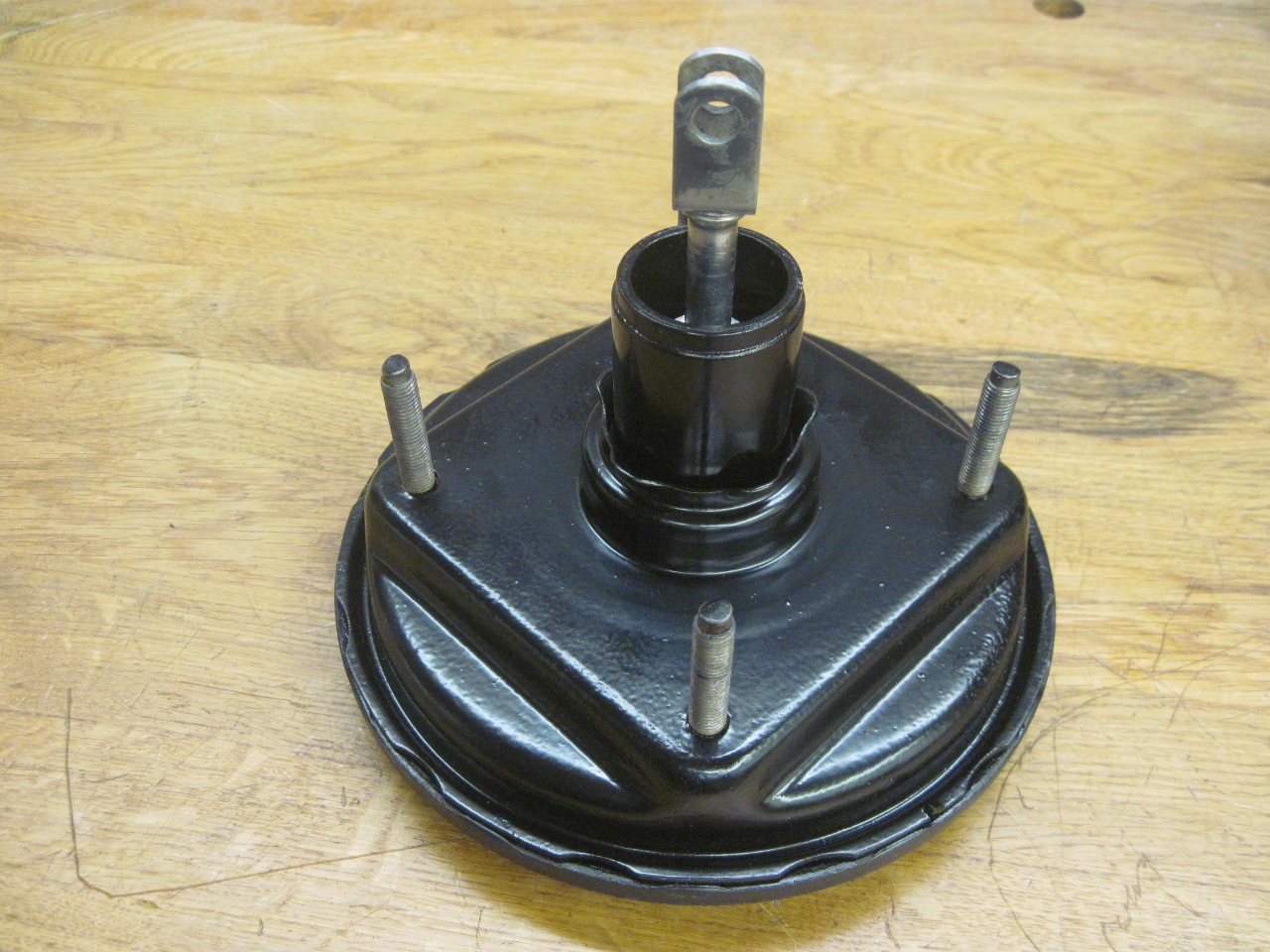
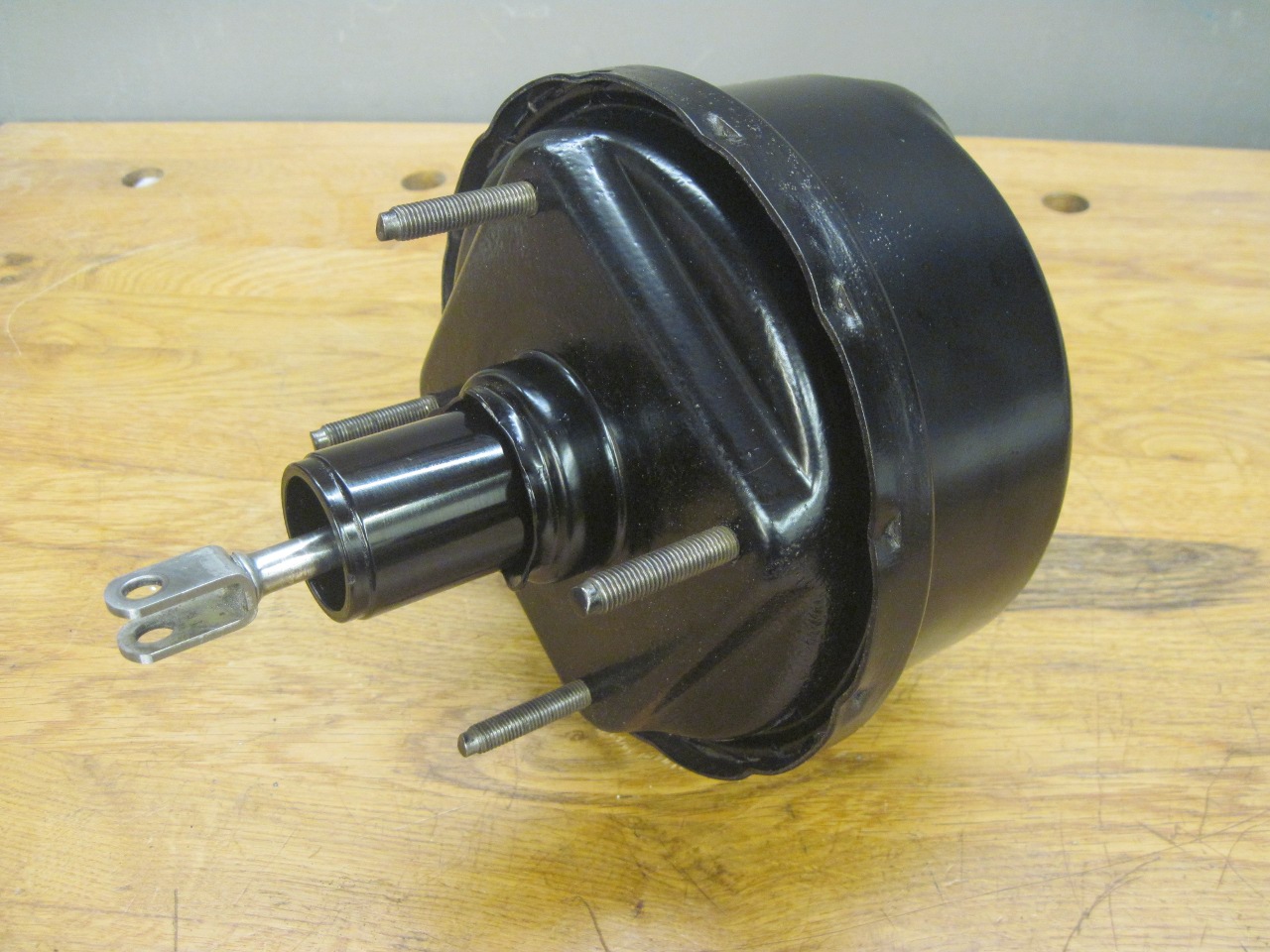
Commensurate
with the rest of the car, my servo was a greasy, dirty, rusty lump.
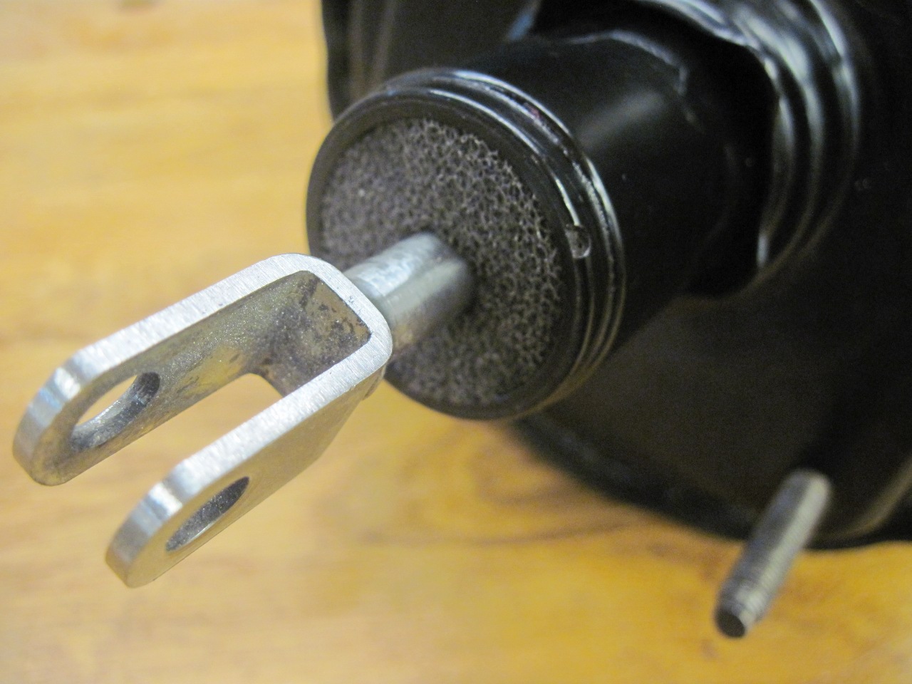
Notice the debris inside the nose around the fork. That is
the remains of a filter. More on that later.
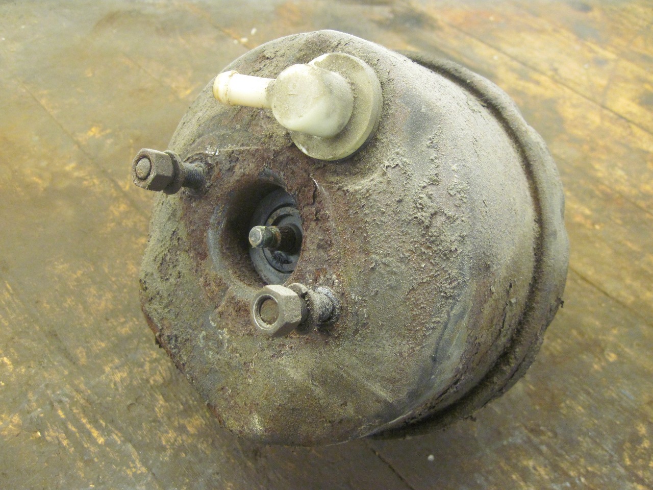
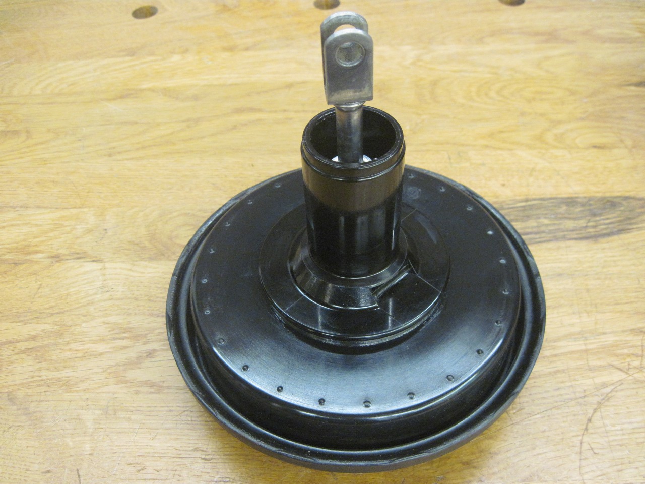
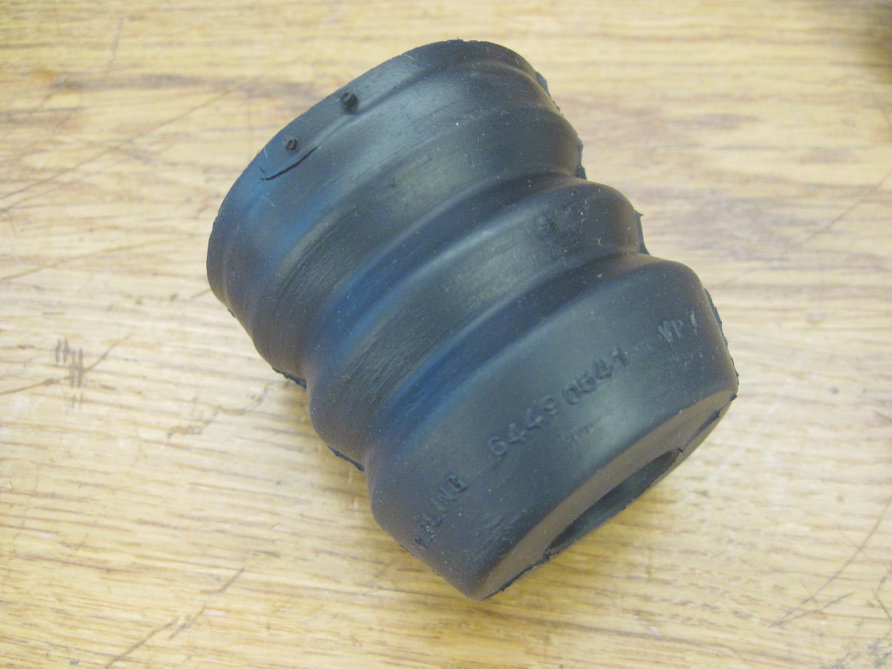
There
are a few things that can be easily taken off the unit--the spacer, the
dust cover, and with a little more dermination, the front seal and the
"non return valve" where the hose from the manifold connects.
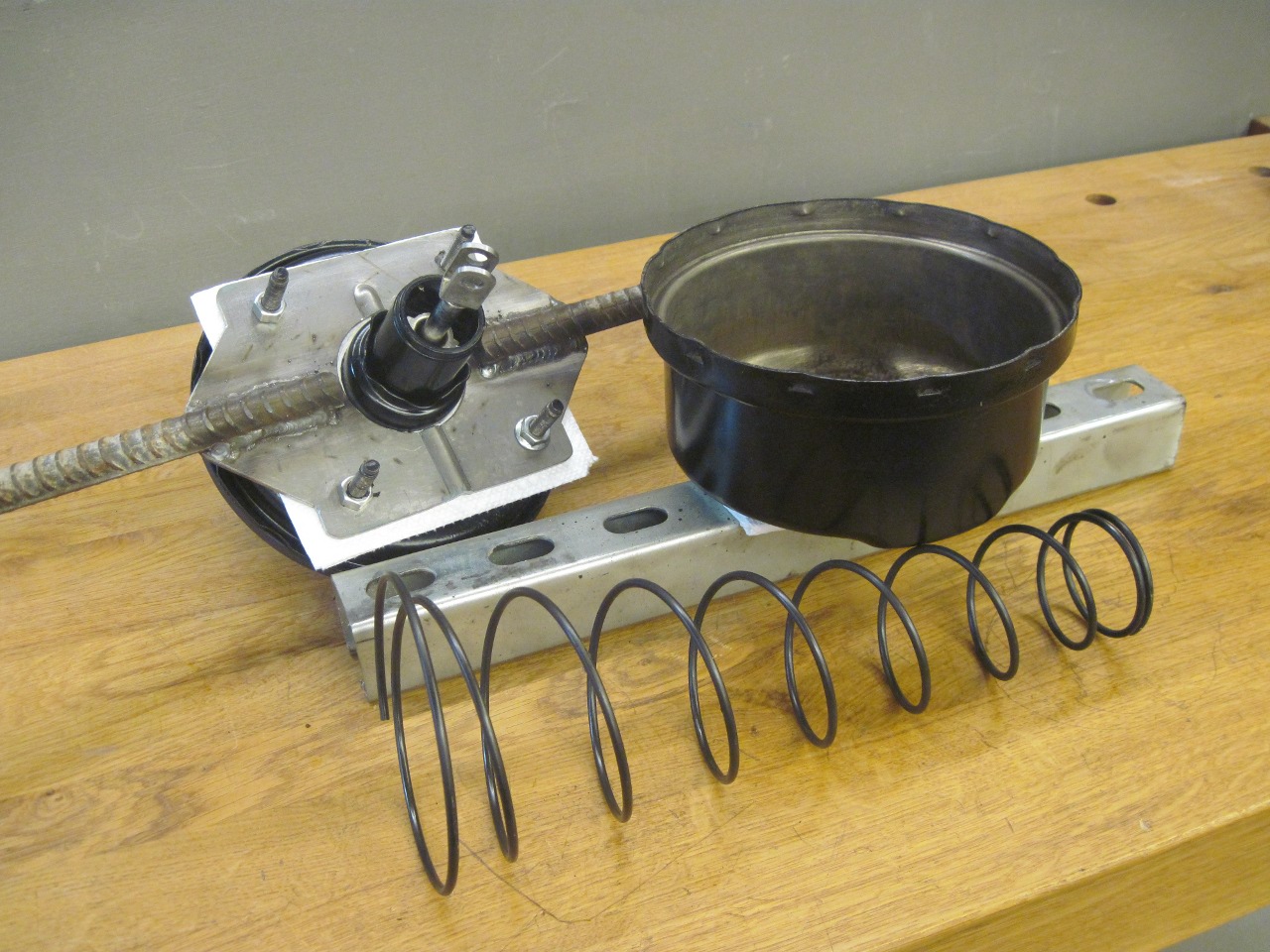
But for the really interesting stuff the case has to be
opened.
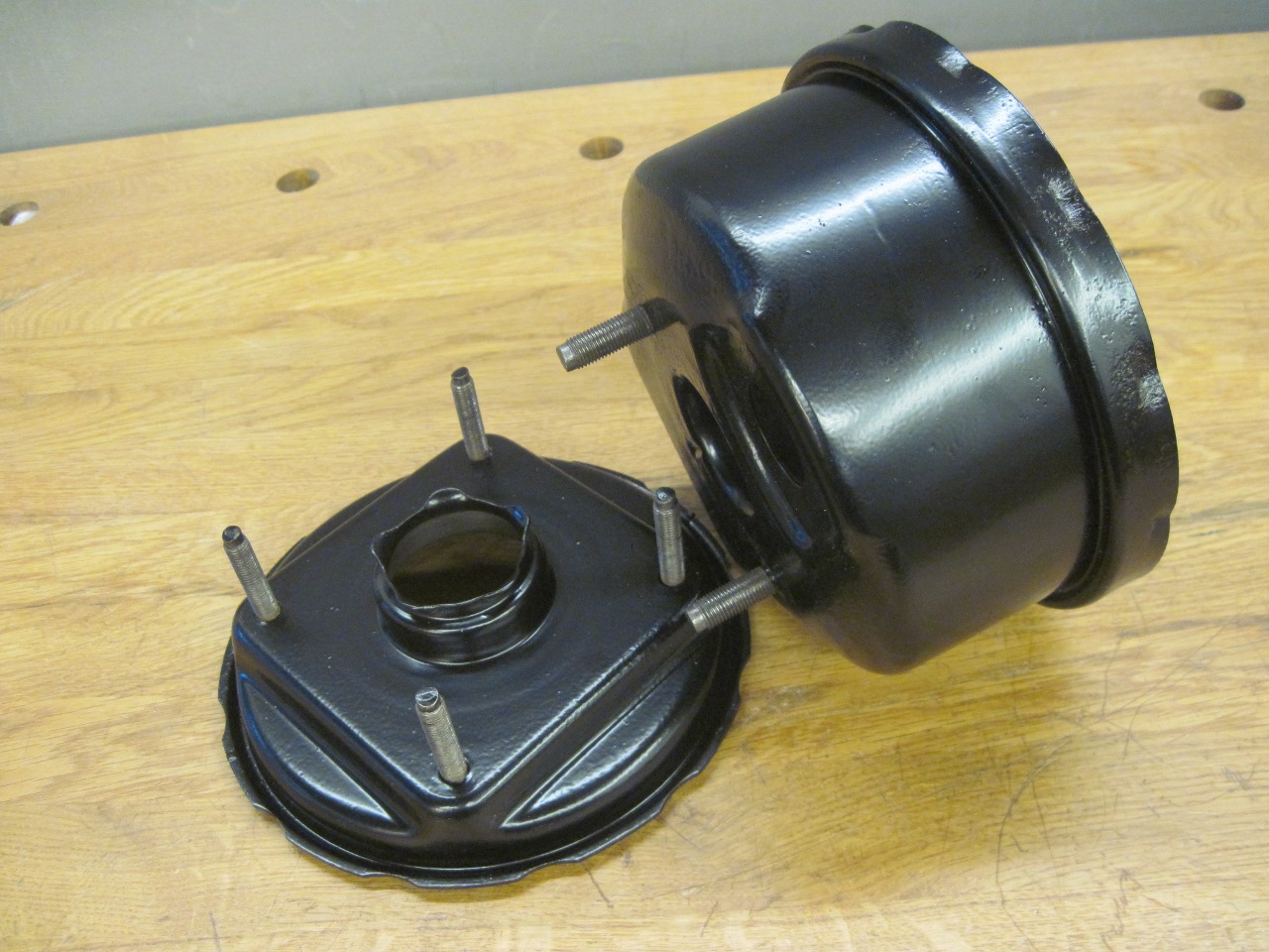
The case is in two halves, joined by a bayonet
style joint. The circumference of the internal rubber diaphragm
is captured in the joint and is under considerable compression, so the
joint isn't a pushover. I made some tools similar to those
described on the Buckeye site.
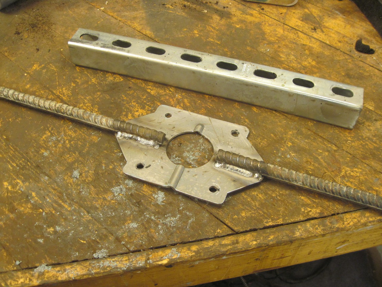
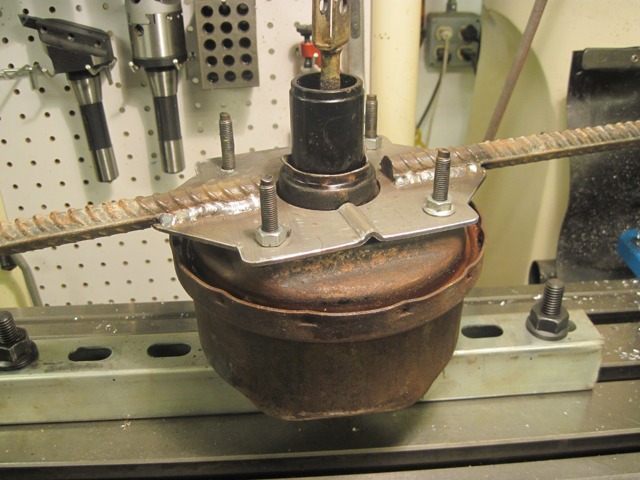
With
a cheater bar and some enthusiastic hammer work, the joint finally gave
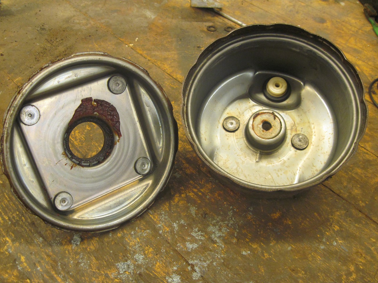
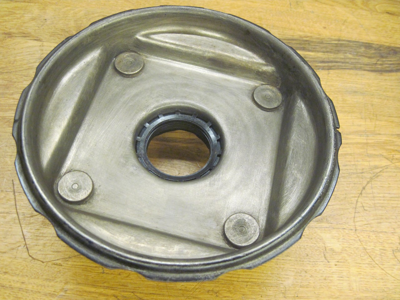
up. Imagine my happy surprise when I removed the internal
diaphragm/carrier assembly and saw that the inside of the cases were in
pristine condition! Other than some congealed 40 year old grease,
the inside surfaces looked brand new.

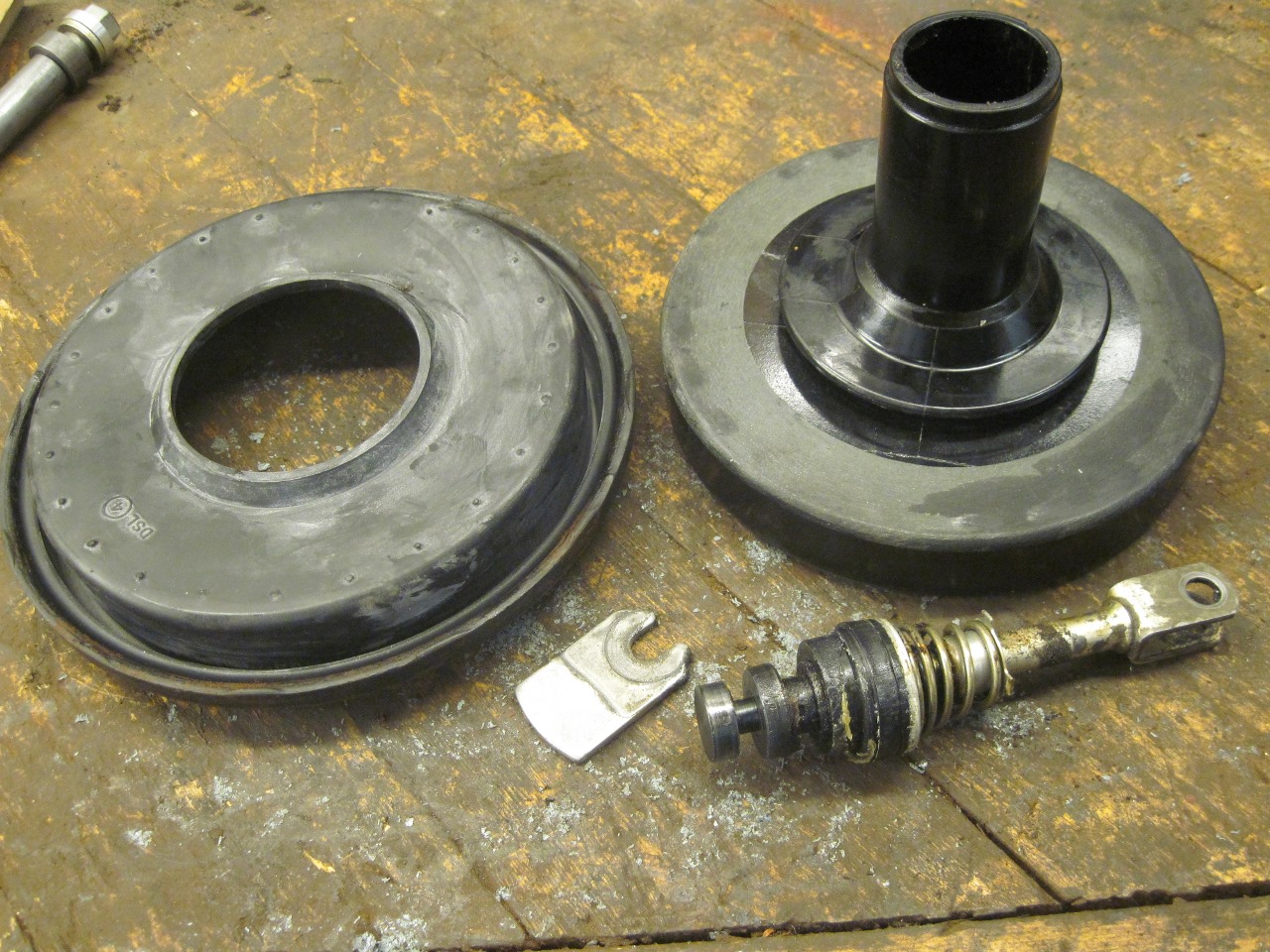
Encouraged,
I turned to the internal parts. The large rubber diaphragm is
carried by a large plastic (phenolic, I think) carrier. Inside
the central bore of the cerrier is a valve assembly. The valve
assembly is located and retained in the bore with the little forked key.
The
diaphragm appeared to be intact, and was still very supple, but had an
uneven surface coating. I'm guessing it was the parting compound
from the molding process. After a little cleanup, it looked much
better. I couldn't see anything wrong with the diaphragm.

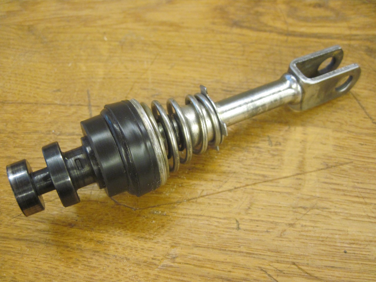
The
valve assembly appeared to be staked together so I didn't disassemble
it. I believe when these were available, they were sold as a
unit.
There are two rubber parts in the assembly.
One acts as a seal inside the bore of the diaphragm cerrier, and
the other seats on an opening in the carrier that connects the chambers
on either side of the diaphragm. With the brake pedal not
pushed, the volumes in back of and in front of the diaphragm are
connected, so that the engine vacuum evacuates both chambers.
When the pedal is pushed, first the valve assembly closes off the
connection between the two chambers, and then opens the rear chamber to
atmospheric pressure through the cetral bore in the carrier. The
imbalance in pressure pushes the carrier forward, adding force to the
pedal force.
The
bore in the carrier was shiny and smooth, and the valve assembly
seemed to still be a nice fit. A little rubber preservative made
the diaphragm look even better. I was pretty encouraged at this
point.
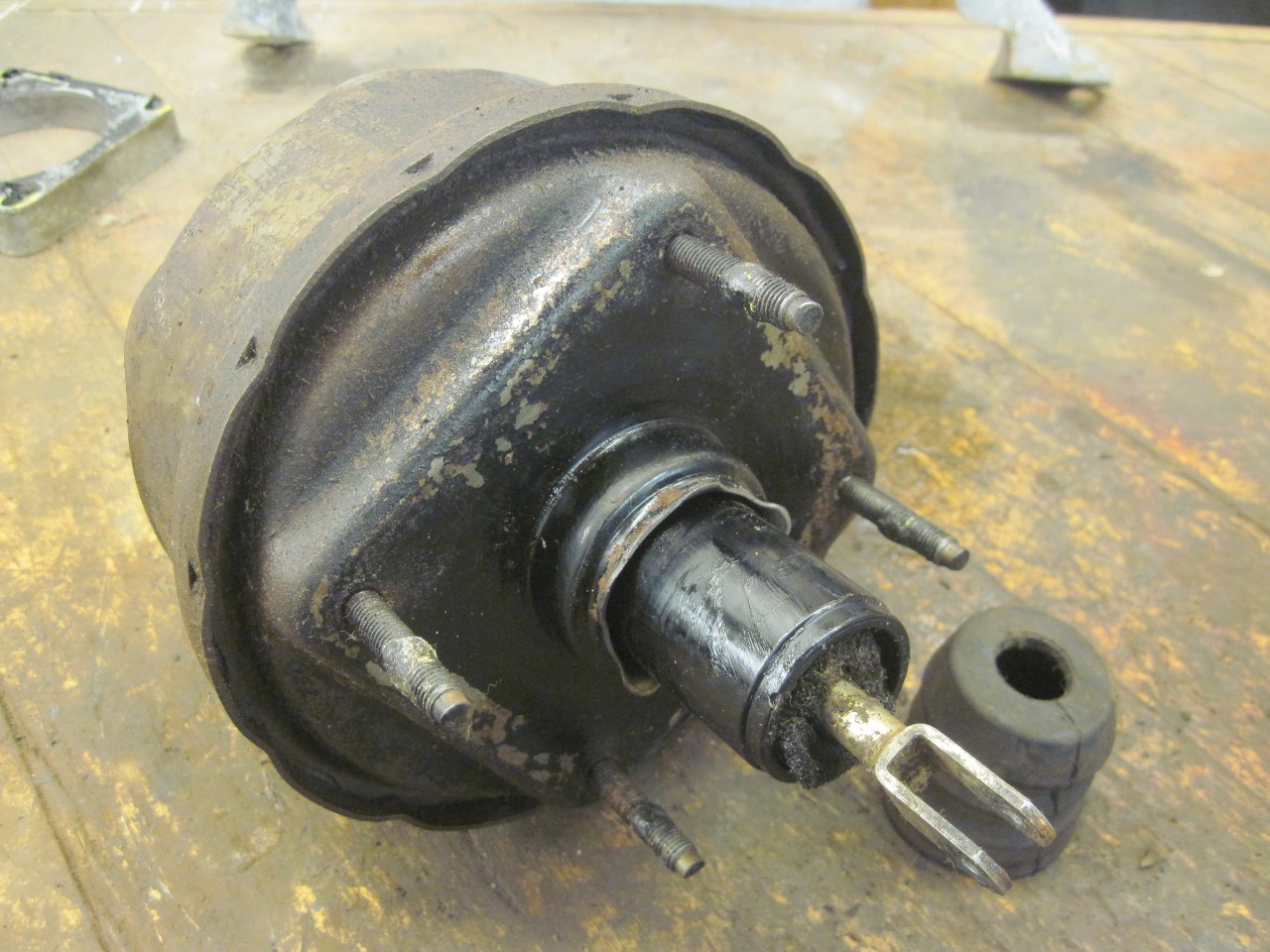
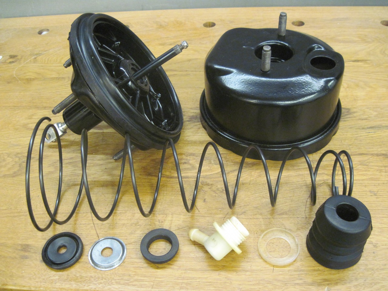
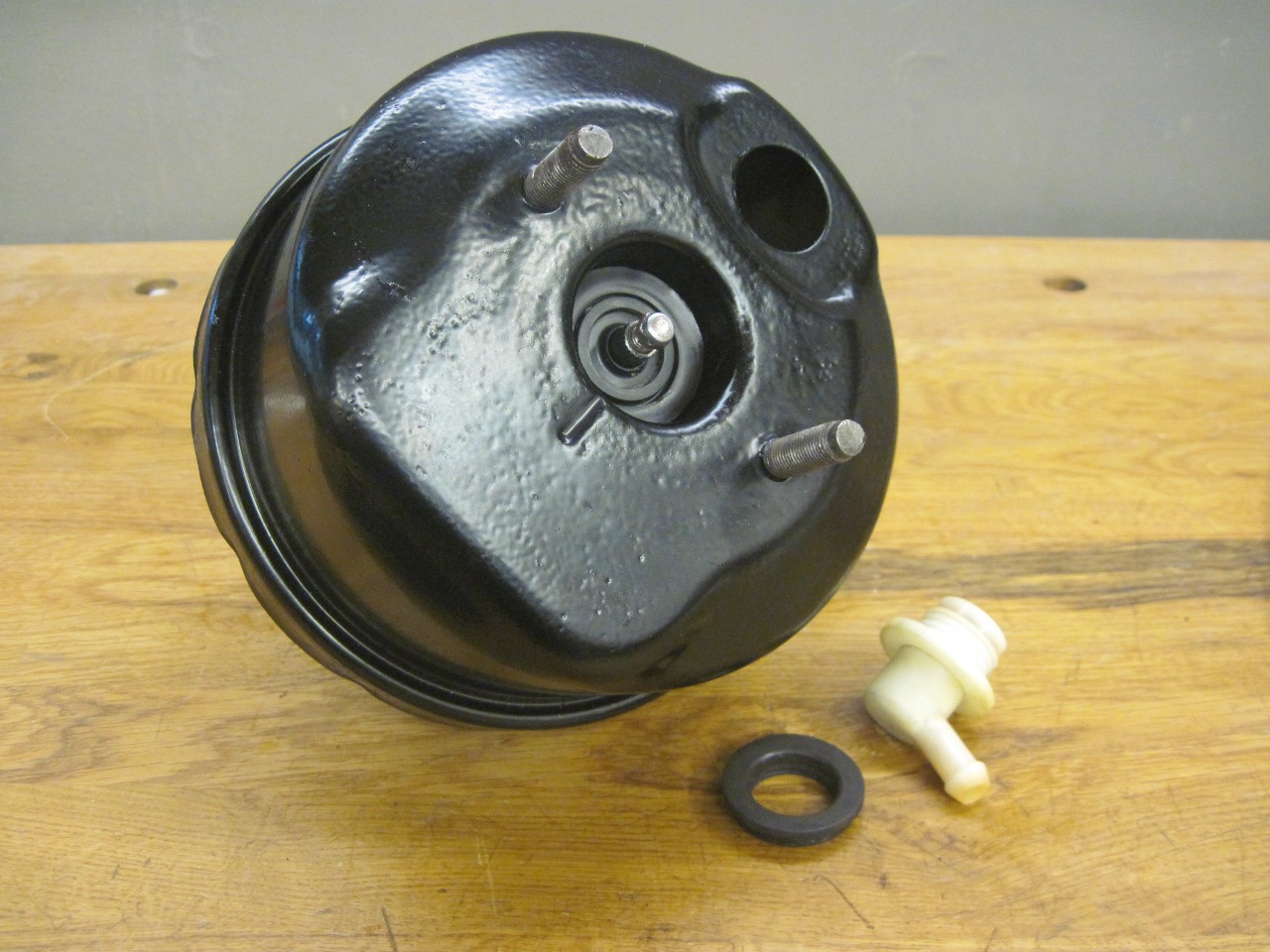
I cleaned up the outside of the cases and powder coated them with a semigloss black.

This
assembly seals around the neck of the diaphragm carrier. Again,
the cleaned and lubricated rubber seemed to still be a good fit.
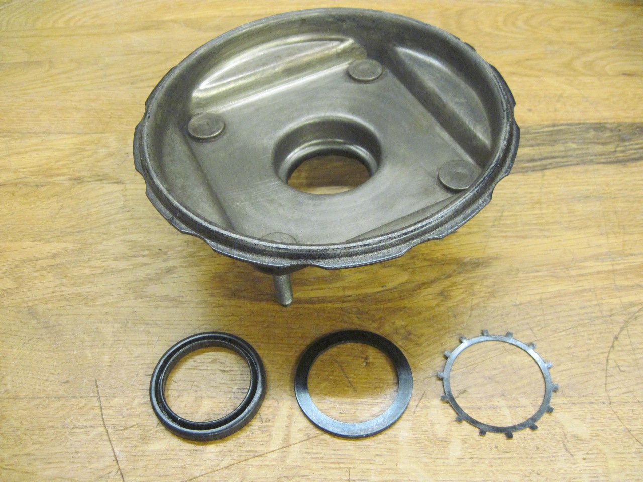
The rest of the parts, all original.
This
dust cover is one of the parts that is available for the servo, but
after I cleaned it up, I could see no reason to replace it. It
was still pliable, and a good fit on the case. If I got this
cover in the mail as a replacement, I would be totally satisfied with
it.
The
cases went back together much easier than they came apart. Some
rubber lube on the diaphragm circumference helped a lot. The
white pads protect the paint. I tested the check valve before I
put it back in.

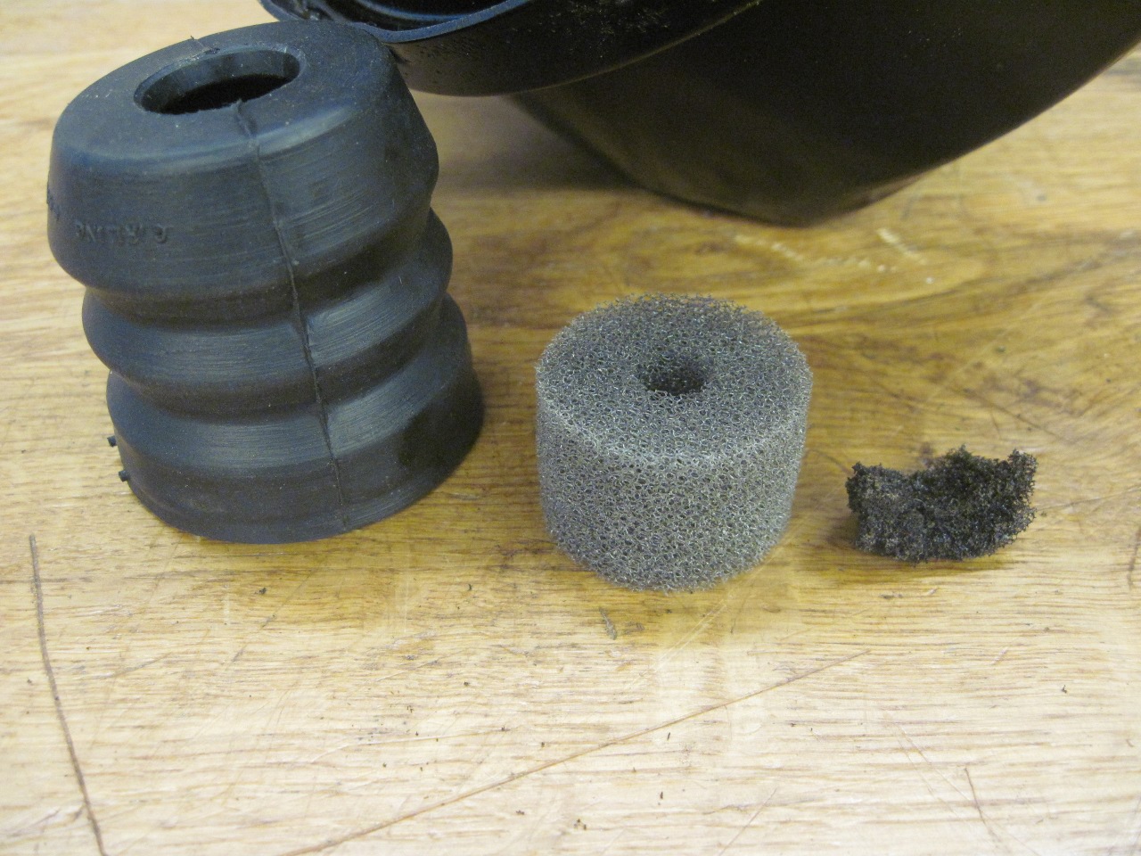
The
last item was the filter inside the nose of the carrier. It
filters the air drawn in to the rear chamber when the vacuum is
released. It was the only really perished part of the entire
servo. It is not available anywhere that I could find. In
the end, I bought a piece of 1" thick polyurethane open cell filter
media, and cut a cylindrical piece out of it. It doesn't look too
far off from what's left of the original in the middle picture.

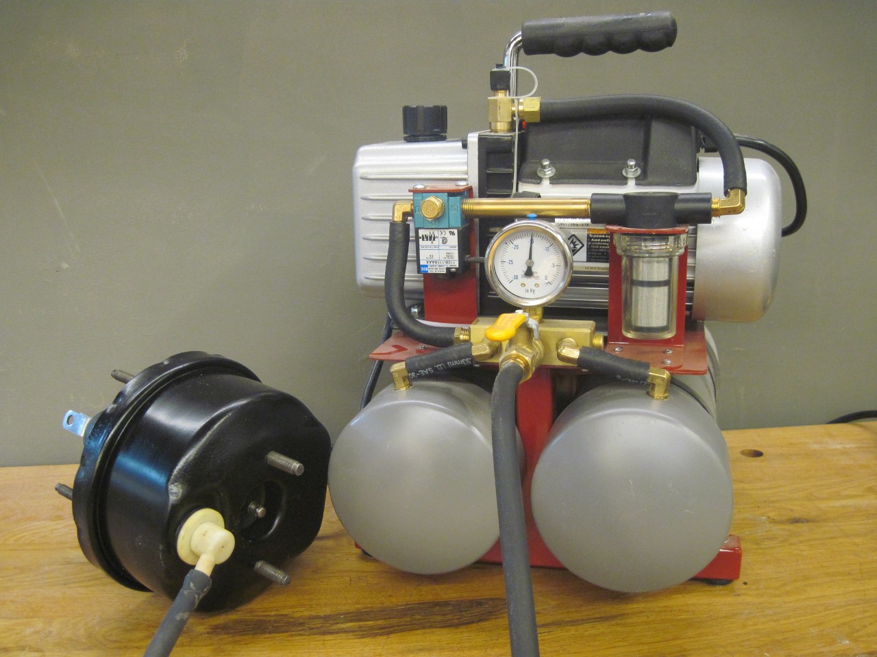
So
here is the critical question: Can all of these 40+ year old
rubber parts still contain a vacuum? I pumped the unit down to 15
inches of vacuum, and turned the pump off. It looked pretty
steady. One hour later, the vacuum was a little under 14 inches.
In the interest of full disclosure, I will point out that since I
didn't have another vacuum gauge, I left the valve from the pump open
so I could use the pump's gauge. This added the pump's reservoir
volume to that of the servo, so it's possible that the servo alone
might leak down a little faster. I was hesitant to actually
actuate the servo because I wasn't sure how it would react without the
load of a master sylinder attached.
I
really couldn't have hoped that this exercise would have turned out
better. It is still hard for me to believe that these 40 year old
rubber parts are still doing the job so well. Total cost for the servo
was close to nothing. Some power coat powder, some silicone brake
grease, and $8 for the filter material.
Comments to Ed at: elhollin1@yahoo.com
To my other TR6 pages