To my other TR6 pages.
March 23, 2015
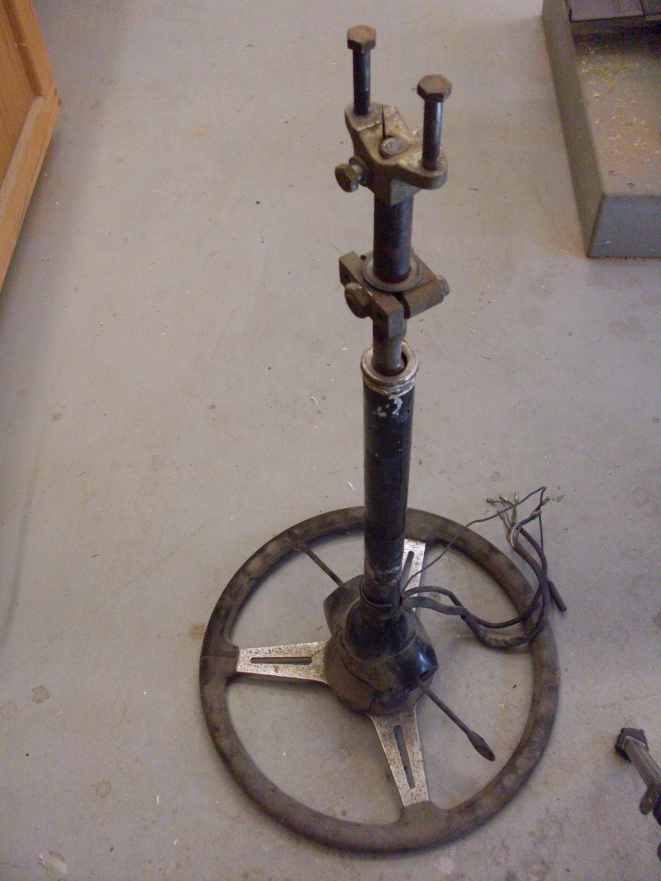
Steering Column
The
steering column's basic job is pretty simple--just hold the steering
wheel in front of the driver, and transmit wheel rotation information
from the top end to the bottom end. It's the little add-ons, like
turn signal, dip, and horn switches that make it more complicated, not
to mention the need to be at least somewhat collapsible and
energy-absorbing in a colision, and to provide a mechanism for a
steering lock.
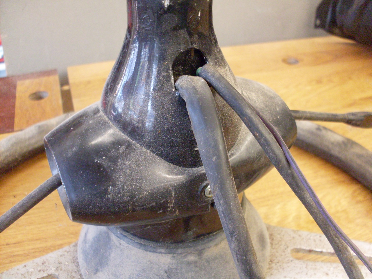
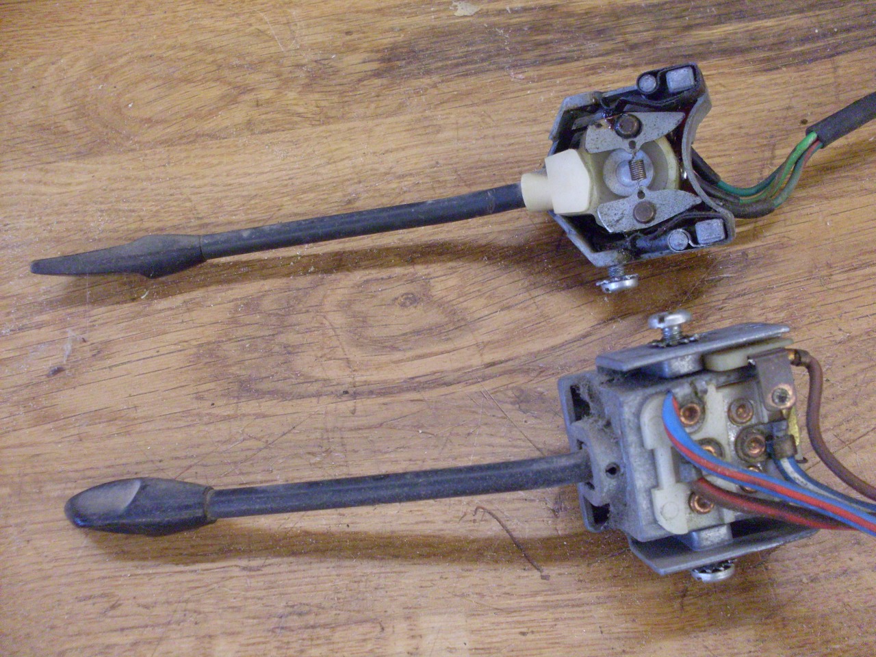
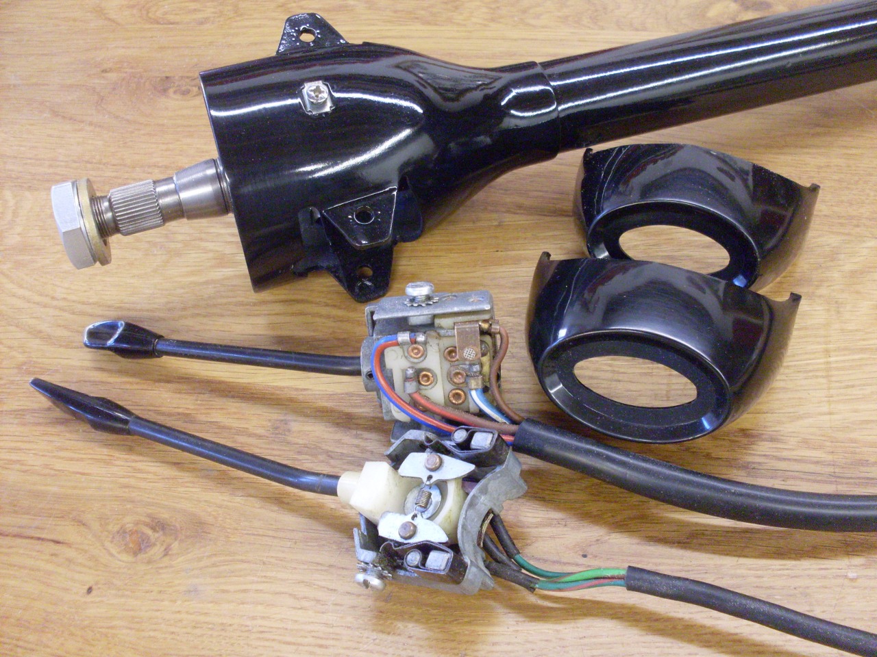
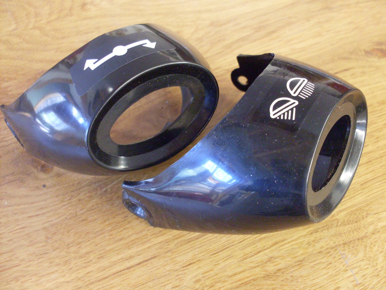
The
dip and turn switches are inside the plastic cowls and their electrical
connections come out through a port on the underside of the outer
column. The switch parts come out pretty easily.
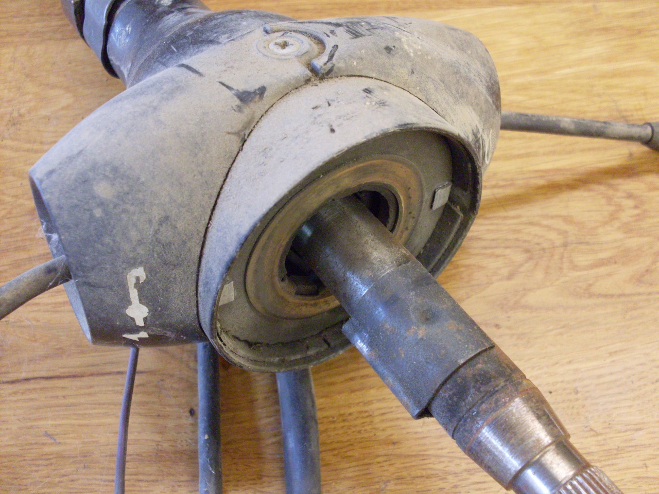
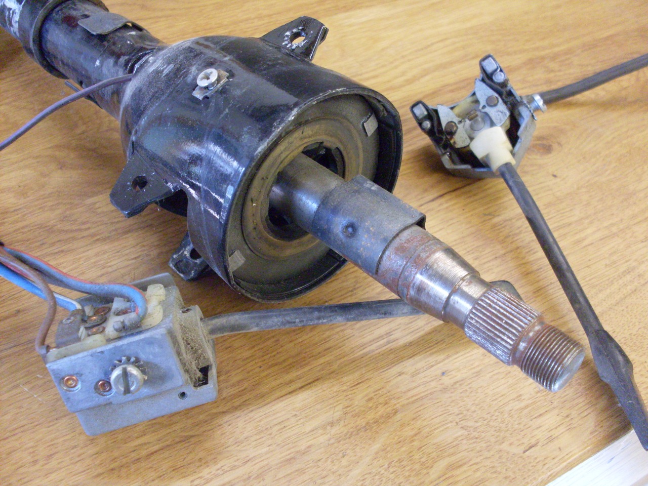
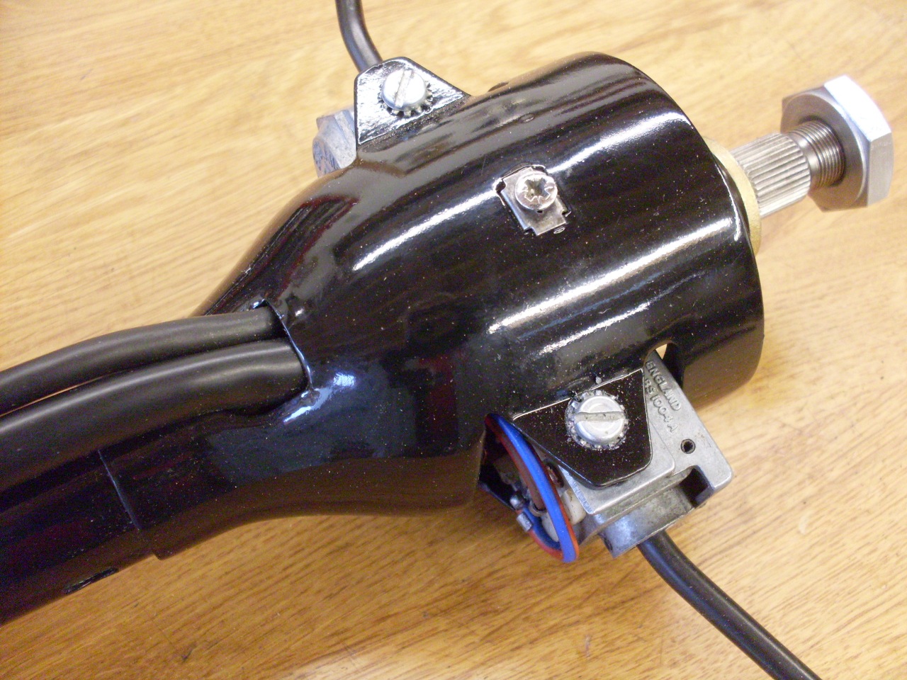
At
the other end of the outer column, there is an aluminum cap held on
with cheesy tape. I suspect the tape was used to hold the cap on
during manufacture, and just left in place. There is no way for
that cap to fall off in service.
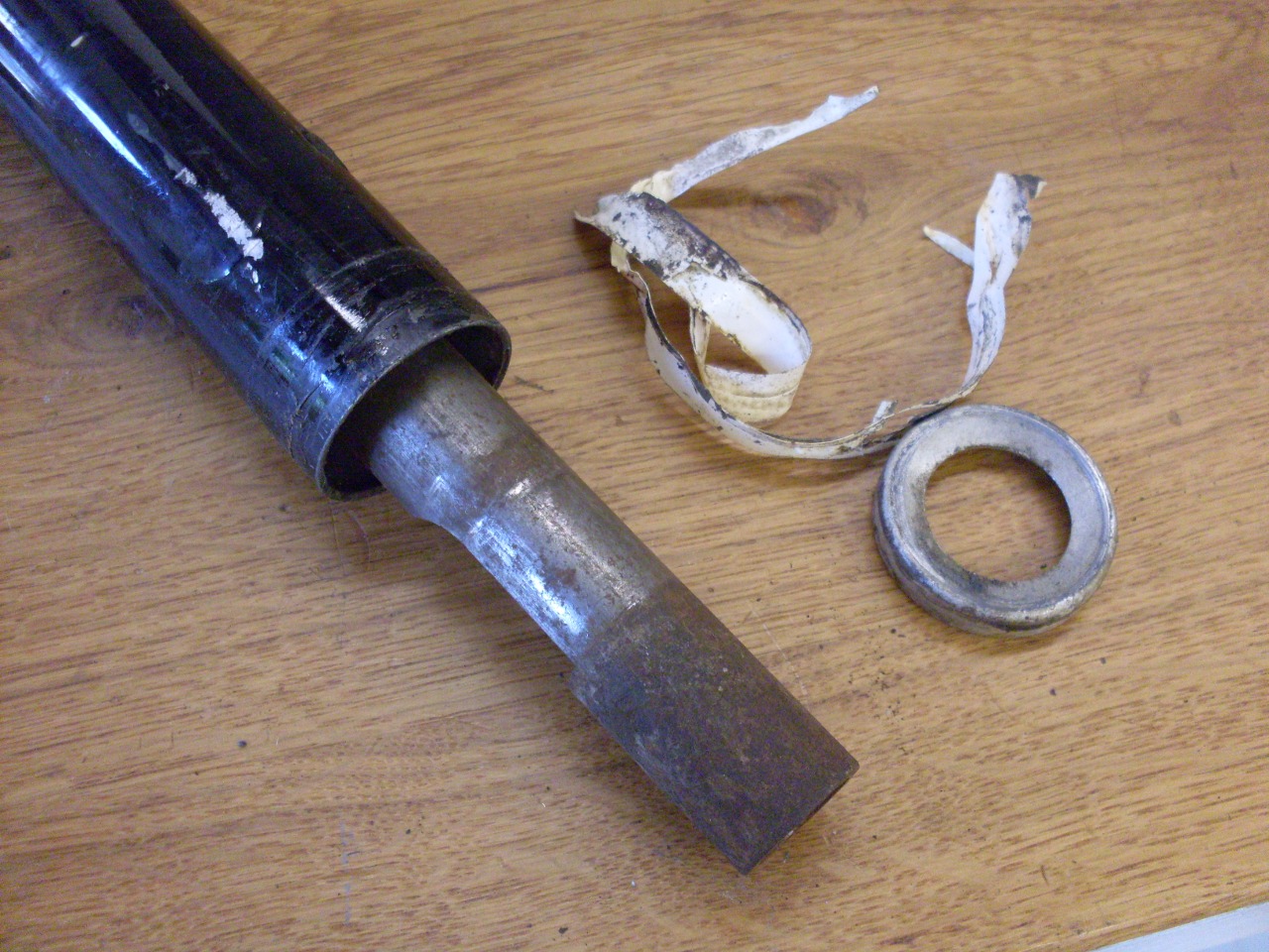
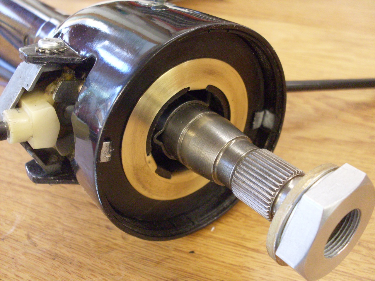
The
steering shaft runs inside the column in two bushing assemblies that
consist of an outer
rubber jacket covering a steel tube, which in turn holds a thin
plastic shell, which is the actual bearing material. The bushes
are held in the tube by the resilience of the rubber, and located by a
couple of buttons on the sides of the rubber that fit into holes in the
column. Removing the bushes is easier if the rubber buttons
are cut or drilled away. The shaft is captive in the column
because of the steering lock feature welded to it between the bearings.
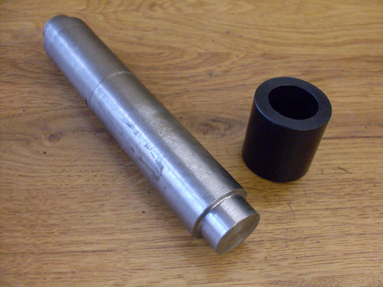
I used the inner shaft as a slide hammer to drive the bushes out.

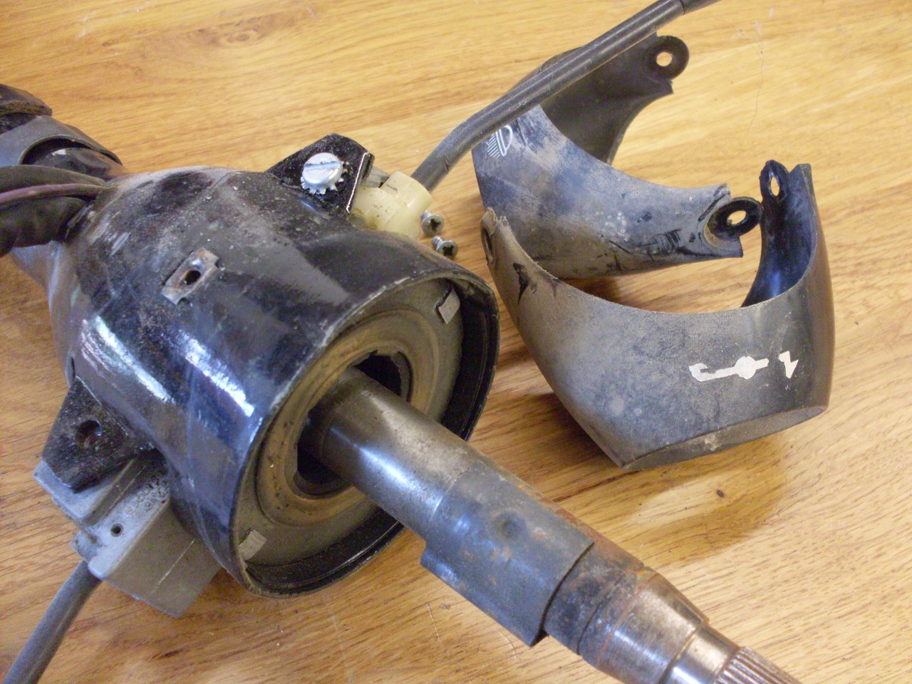
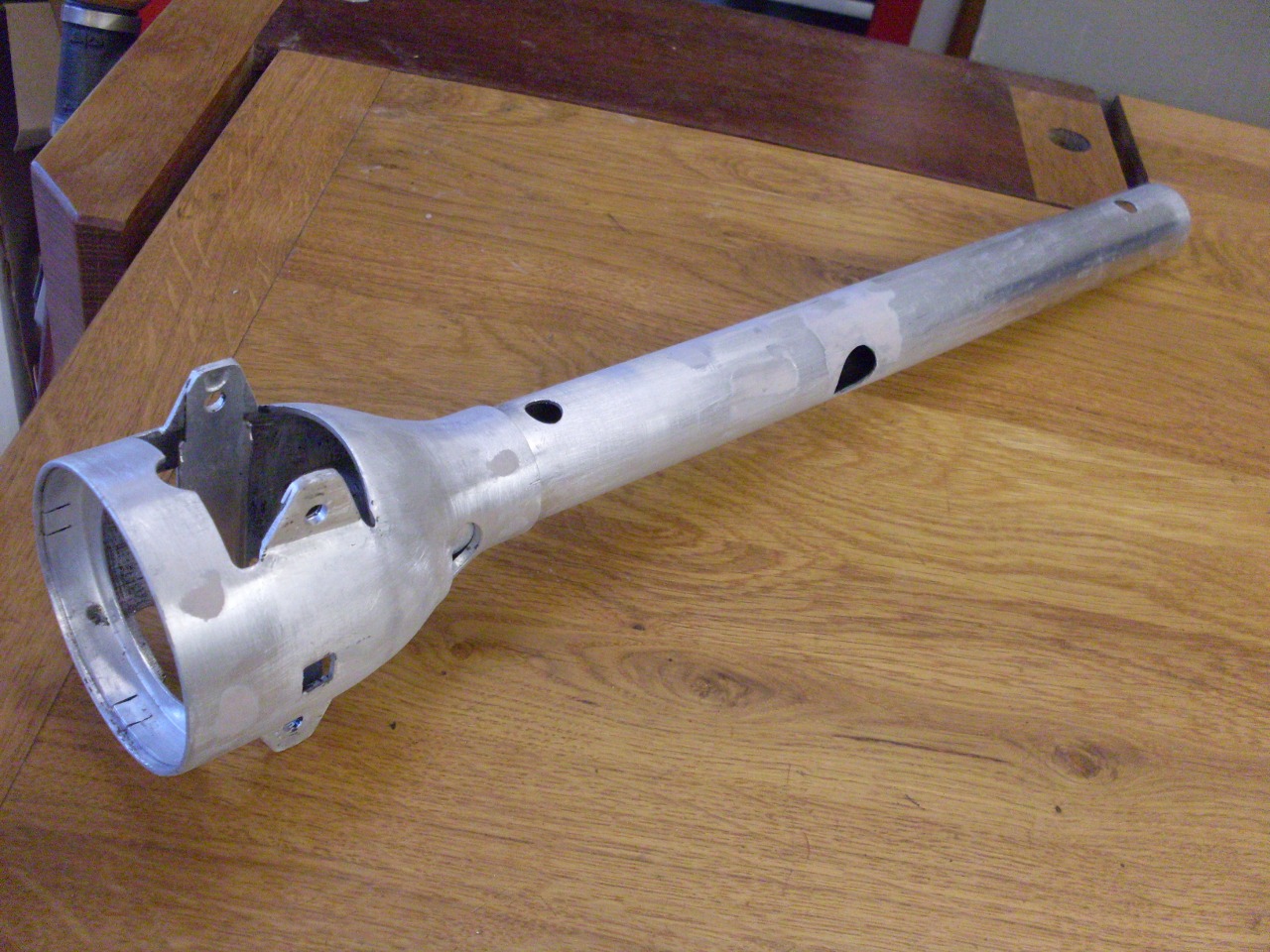
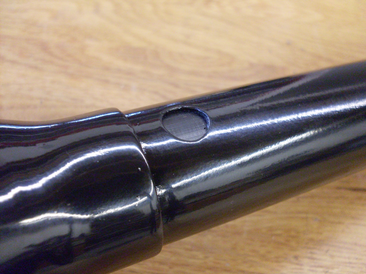
Operations
on the column have to be done with some care, since it is made
from pretty thin, and very soft aluminum. This may be to meet
some US crash safety requirement. The delicate material is
easily distorted as evidenced by the area where one of its fixing
clamps dug into the metal. I suspect the clamp got a little
loose, and allowed the column to wallow in the clamp. The soft
aluminum didn't tolerate that very well.

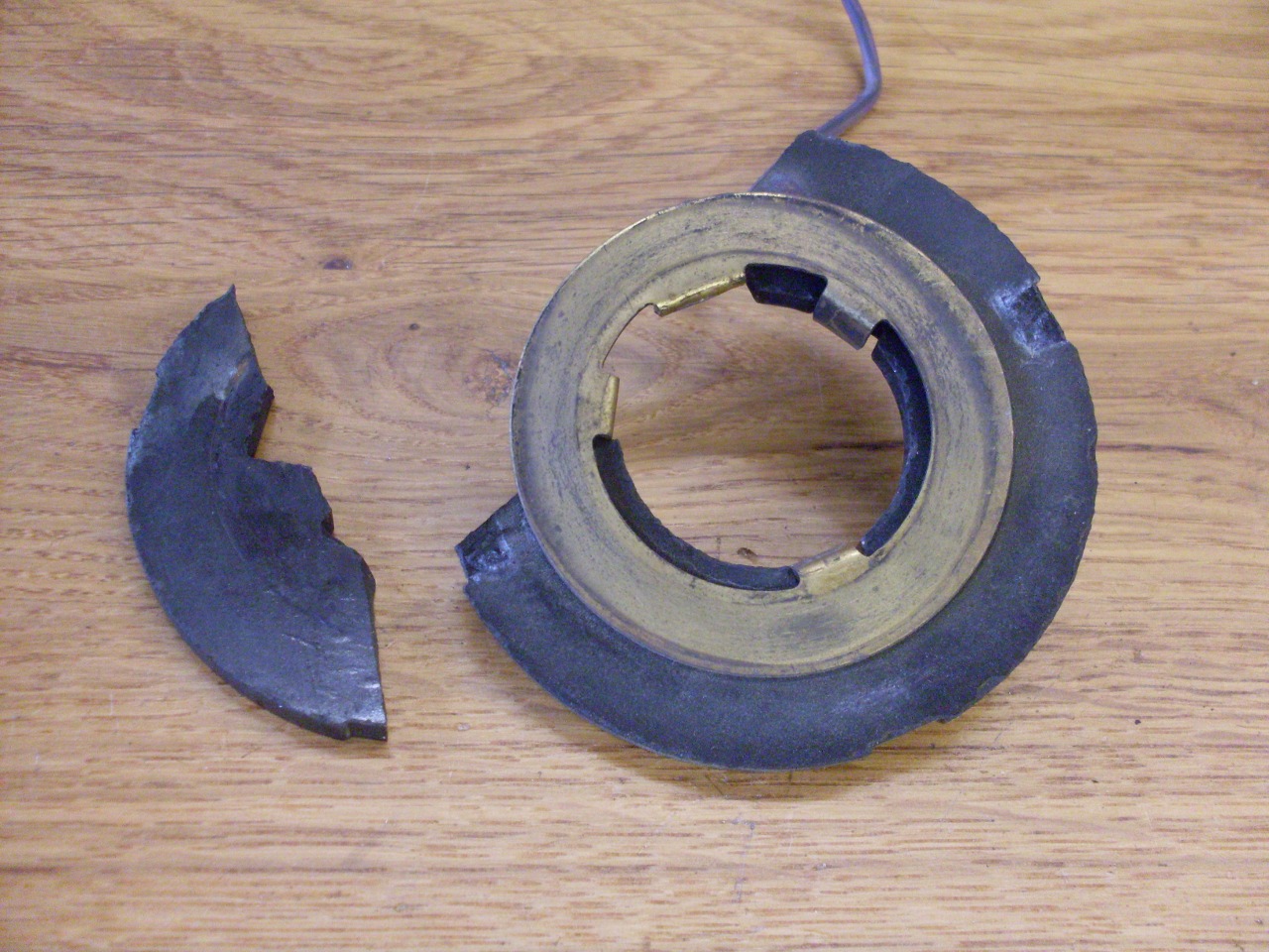
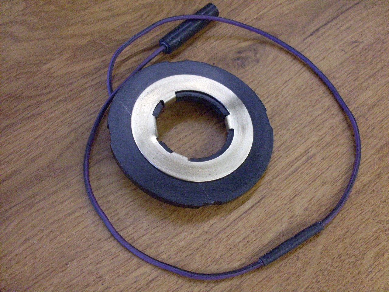
Another
thing to be careful of is the horn slip ring assembly. I wasn't
careful enough. I should have removed it before driving the bushes
out.
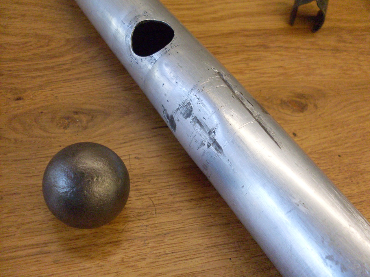
Starting
with the column, I relieved it of its aged paint to get a
better look at the damage done by the fixing clamp. I used an old
trick to fix distortion in tubes--force a greased ball bearing the same
size as the ID of the tube into the bore.
The closest ball I had was 1-1/8", which is a little too small,
so it didn't completely raise the dents, but almost. A little
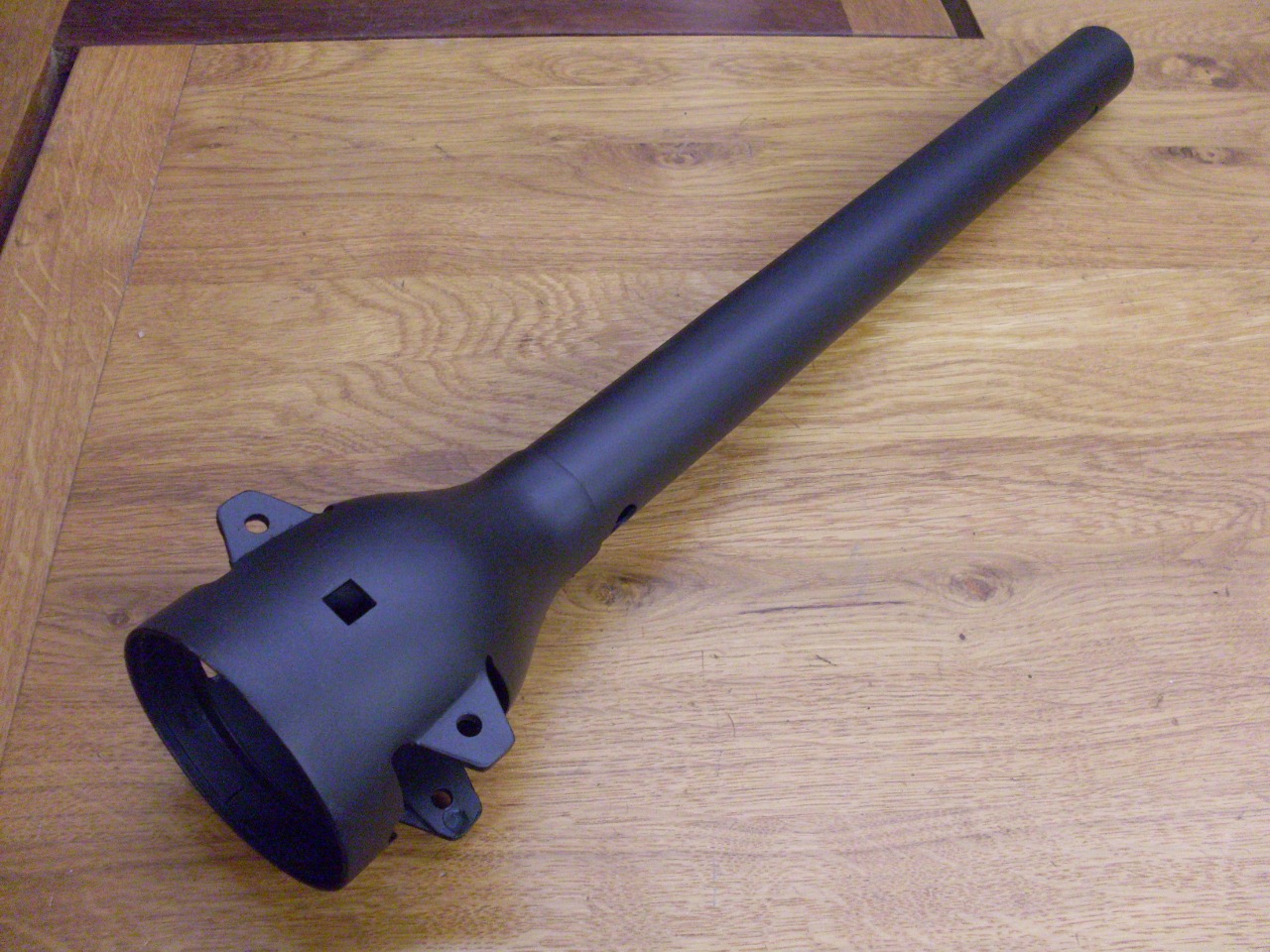
light tapping with a small hammer, a little body filler, primer, and
paint, and the column looked pretty darn good.
I was thinking at this point that I really should have put in the new bushes before painting.
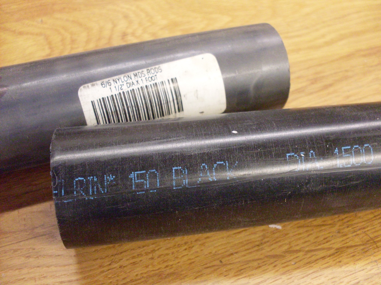
Stock
replacement bushes are available, as are solid plastic ones. I'm
not sure that one is better than the other, but I could make the solid
plastic ones in house for less money than buying either one.
My
first thought was to use some moly-loaded nylon material. Nylon
itself is a pretty good bearing material because of good natural
lubricity, and the addition of molybdenum disulfide makes it even
better. However, one small quirk of nylon is that it can swell a
little bit if it absorbs moisture. I wanted the shaft fit to be
fairly close, and I was a little concerned that a high humidity day
might noticably tighten up the shaft. I don't know how valid my
worry was, but in the end, I decided to use Delrin instead.
Delrin also has good lubricity, but is more stable than nylon
over humidity swings.
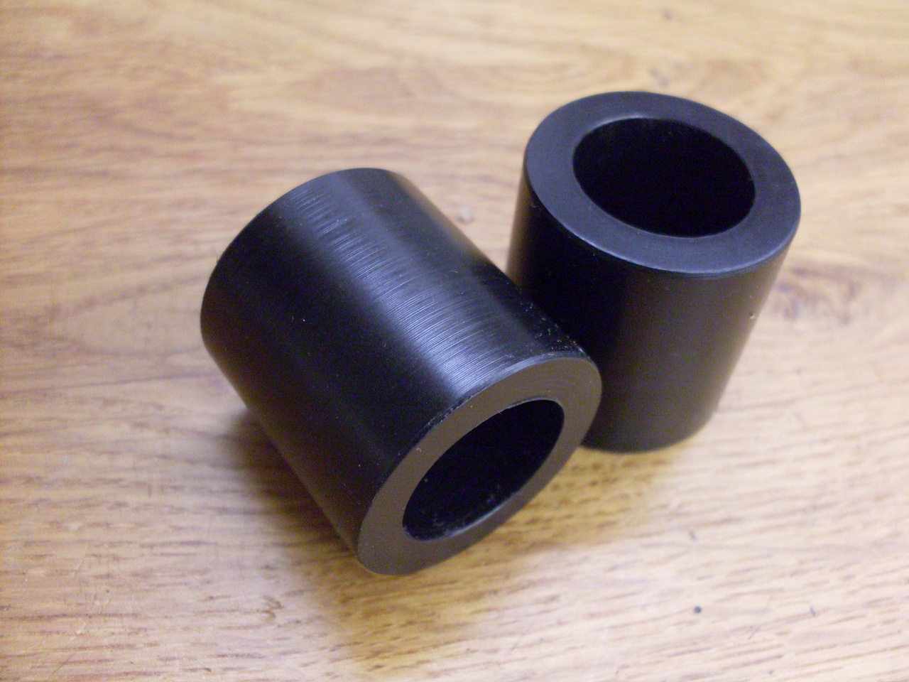
I
made the bushes to be a pretty snug fit in the column. The top
one was driven in with a simple drift, then the inner shaft was
installed, then the lower bush was drifted in with a short piece of
pipe. I considered making little Delrin buttons to fit into shallow
holes drilled in the sides of the bushes to locate them, but the bush
fit was such that I was satisfied that the bushes didn't need any help
to stay put.

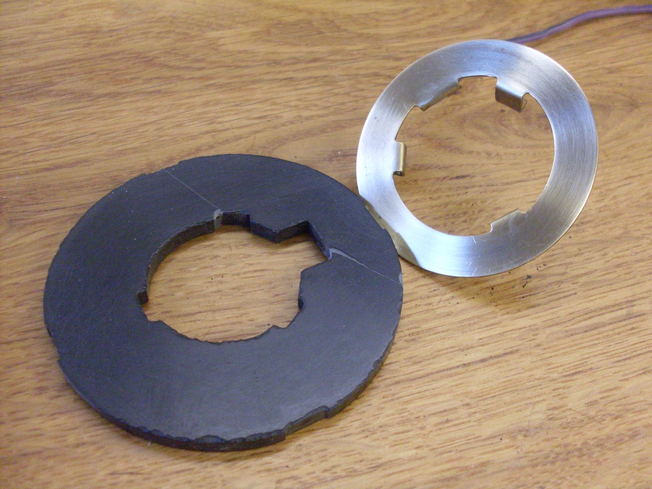
Next
up was the electrics. I glued the broken phenolic horn slip ring
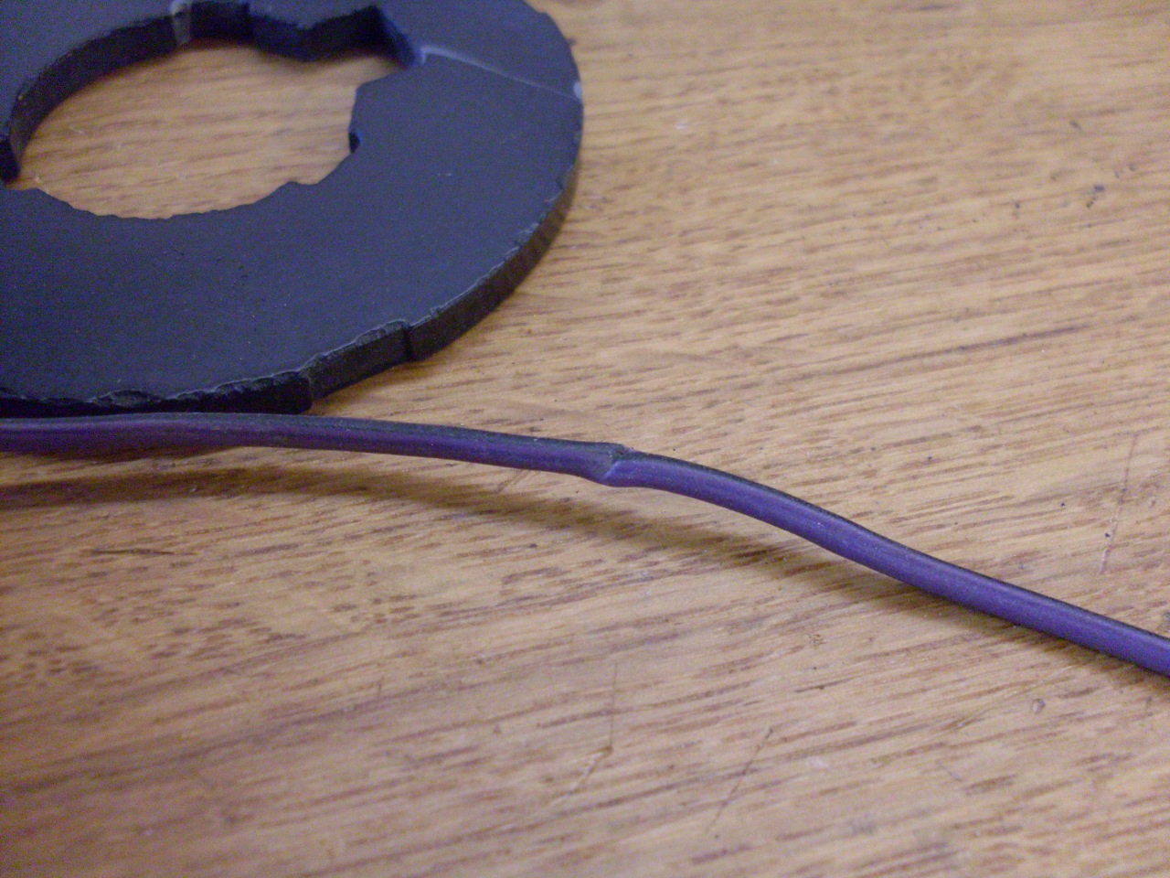
carrier and remounted the slip ring. I noticed the horn wire had
a place where the insulation had been pinched nearly all the way
through. I at first assumed that it was at the point where the
wires emerged from the column, but it was actually much lower. A
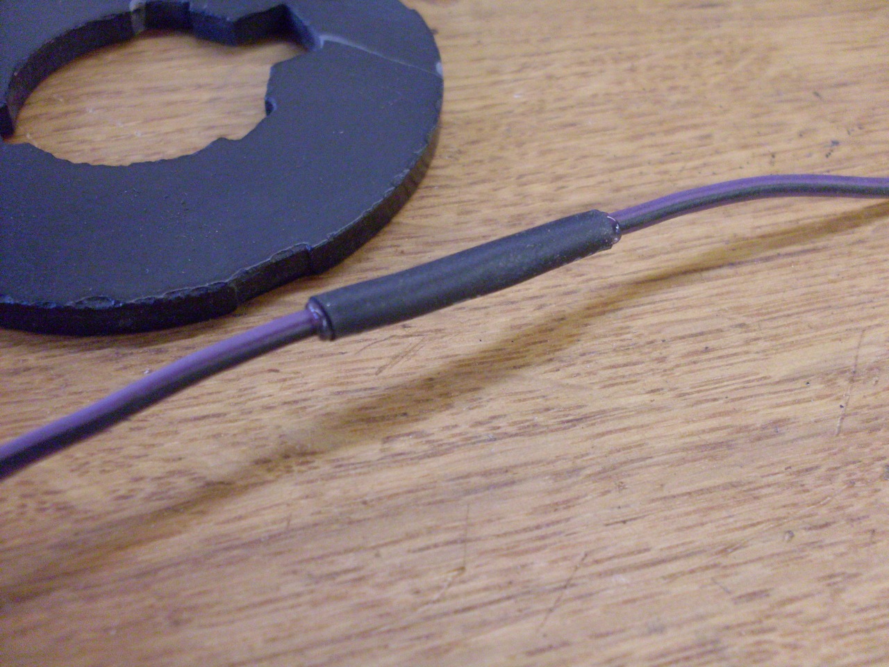
little piece of heat shrink restored theinsulation, and would protect
against any more abrasion.
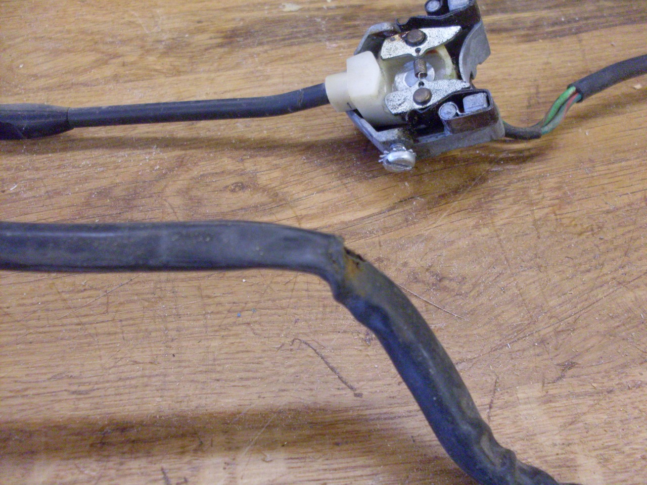
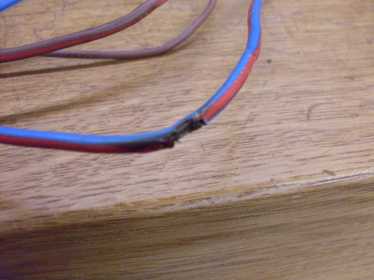
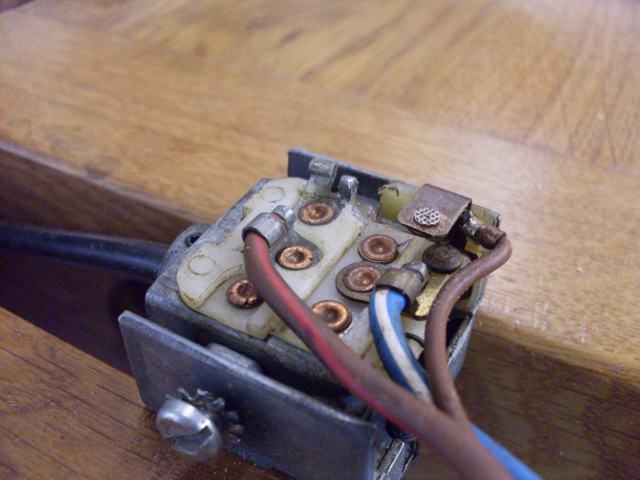
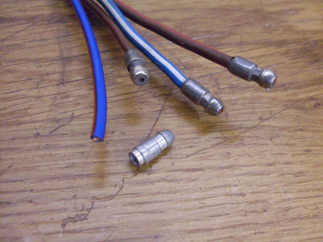
I
checked out both column switches after squirting them inside with a
good contact cleaner. They both checked out OK. There was
some damage to the wires for the dip switch, though. The blue/red
wire's insulation was breached, and the conductors were frayed.
If this wasn't causing trouble (I don't remember), it certainly
would eventually. The damage was where the wires come out of the
column. The other wires were discolored a little, but intact.
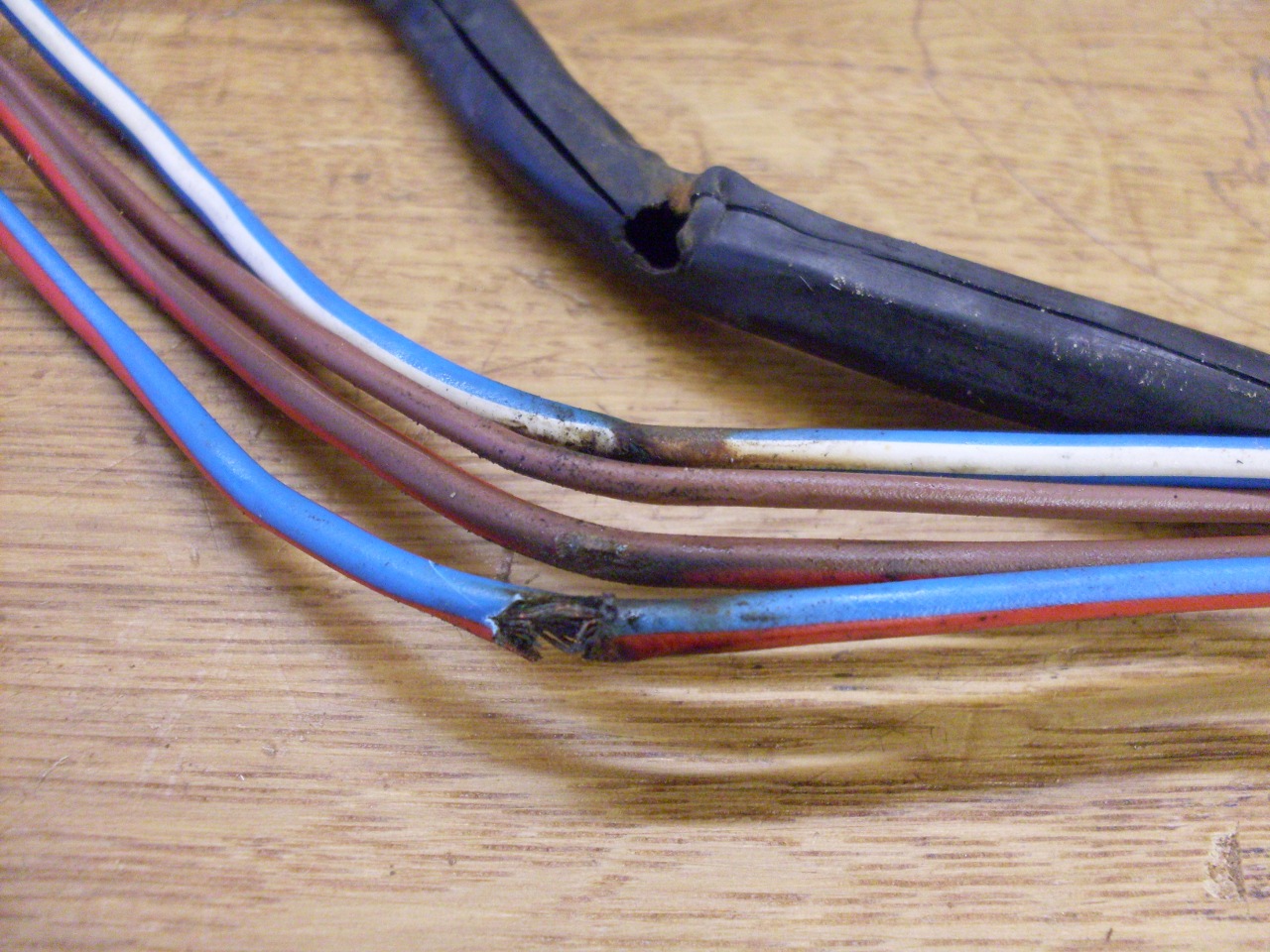
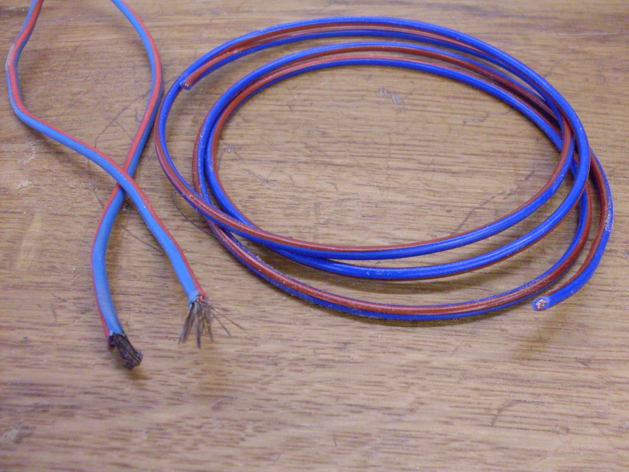
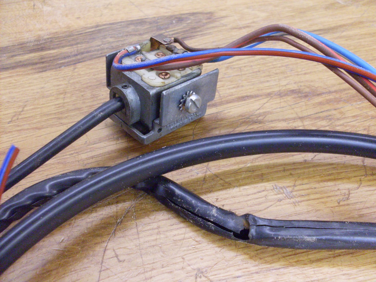
I unsoldered the bad wire and replaced it with a new wire of
the right size and color, and slid it and the others into a new black
vinyl jacket, heavier than the original. British stranded wire is specified by the number of 0.3 mm
strands that make it up. This is 28-strand wire, which I believe
is close to AWG 16 gauge.

Then
added a new bullet. Looks like the originals were all crimped.
I soldered mine. The bullet was left over from my Triumph
bike project, and was for smaller wire, so I had to drill it out
slightly.
Some cosmetic cleanup...
...and the switches are ready to mount.
Can't
forget the so called "trafficator" clip on the shaft. It trips
the turn signal switch back to its center position after a turn.
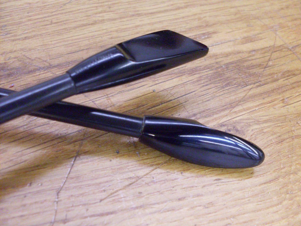
And
applying the new decals to the cowls. The one for the turn
signals is just a sticker, whike the other one is a true water-slide
decal.
Putting
it all together. I was missing one of those screws to mount the
switches. They look to be 8-32, but aren't. When this is
the case, they are surely 3BA screws. Not this time. The
screws are 8-36. While a 36 pitch is the standard UNF thread for
a #8 screw, it isn't very common. I think it's the first time
I've seen one.
Also added an extra piece of heat shrink to the area where the wires come out of the column for additional insurance.

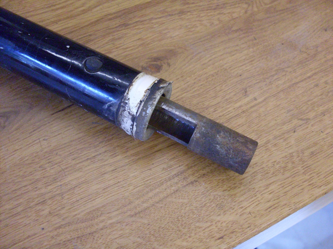
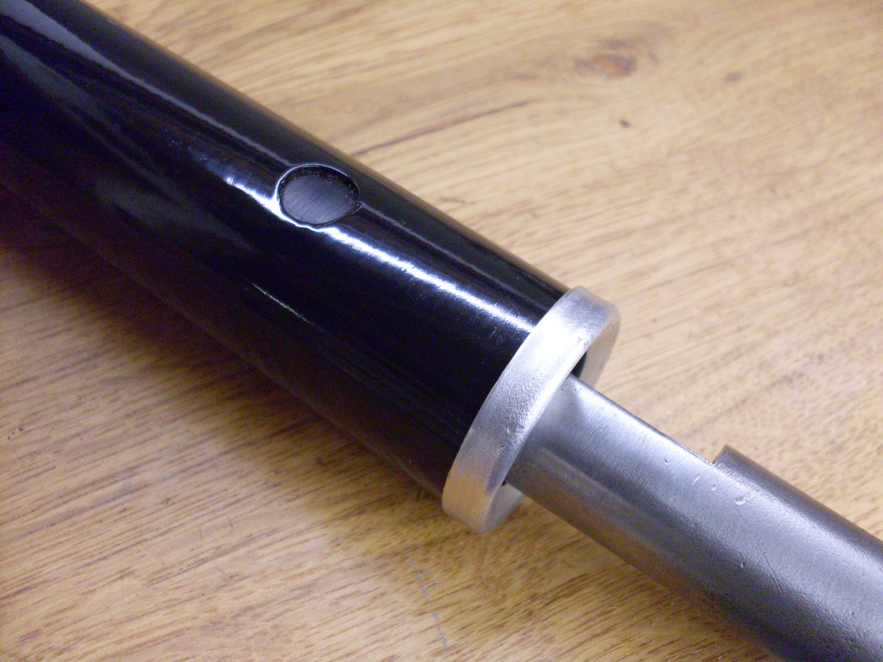
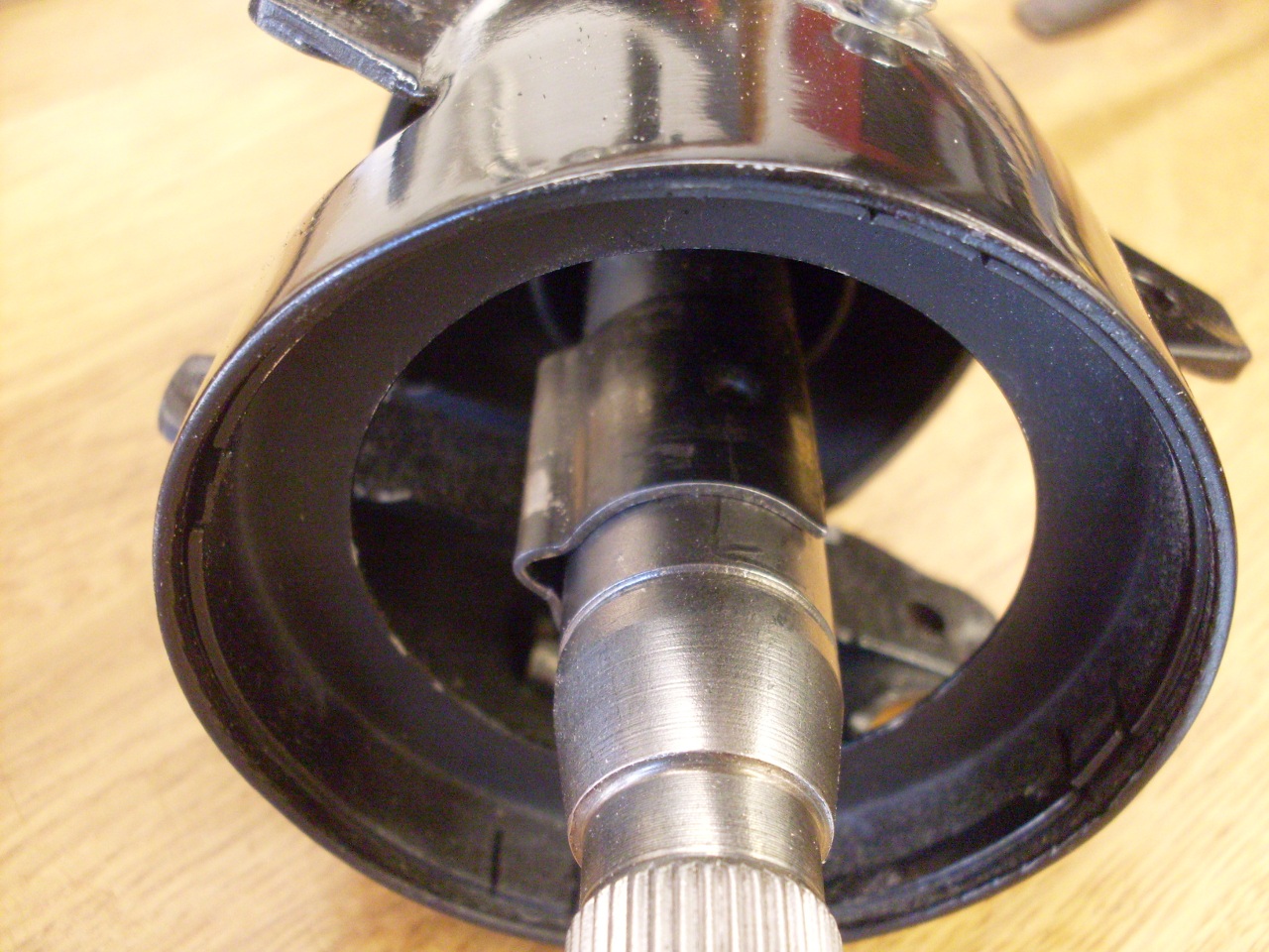
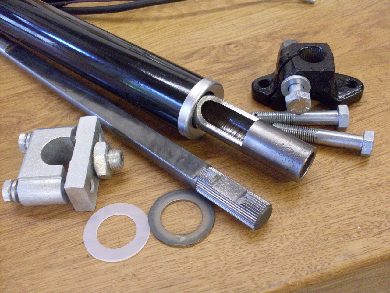
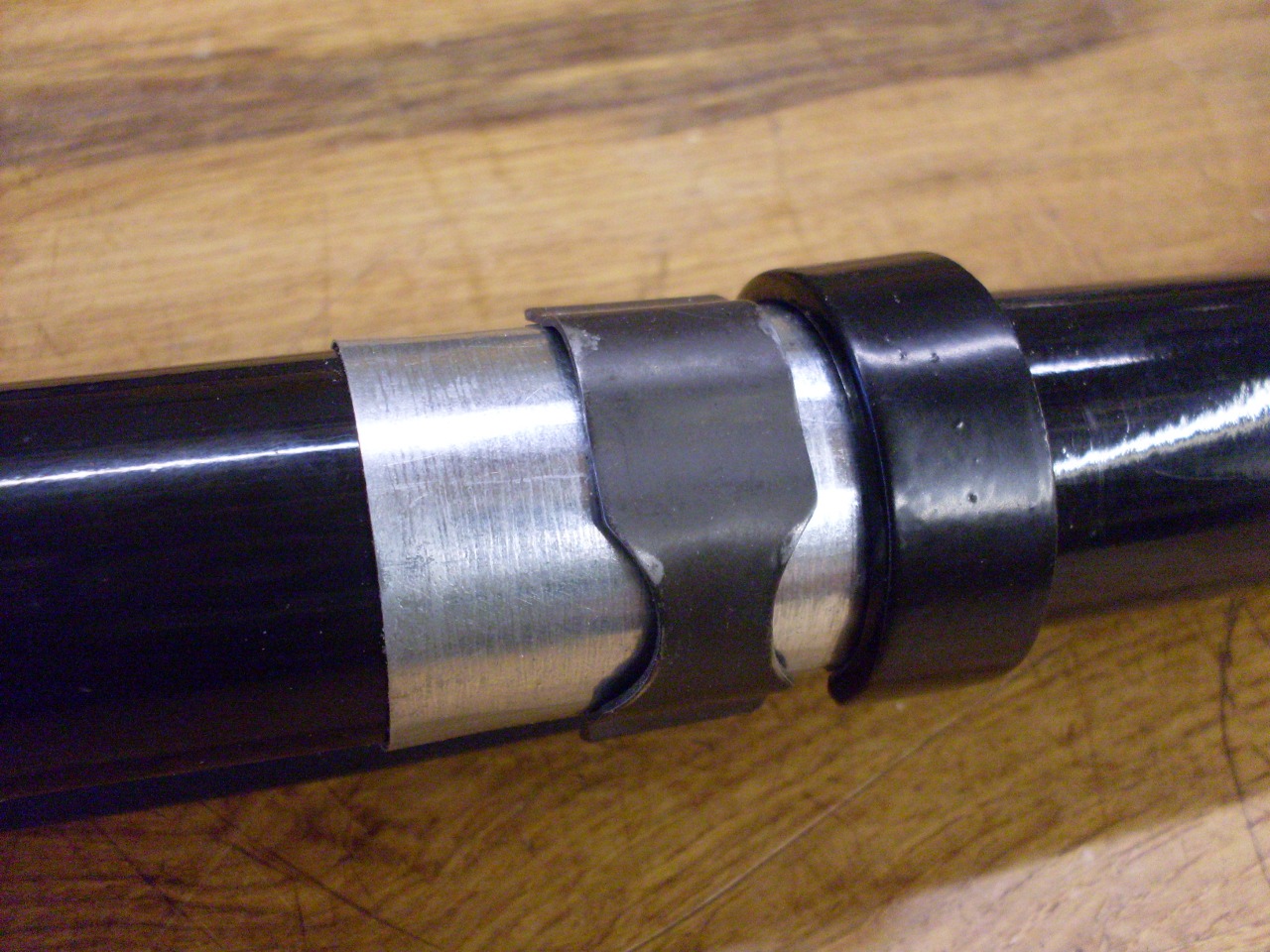
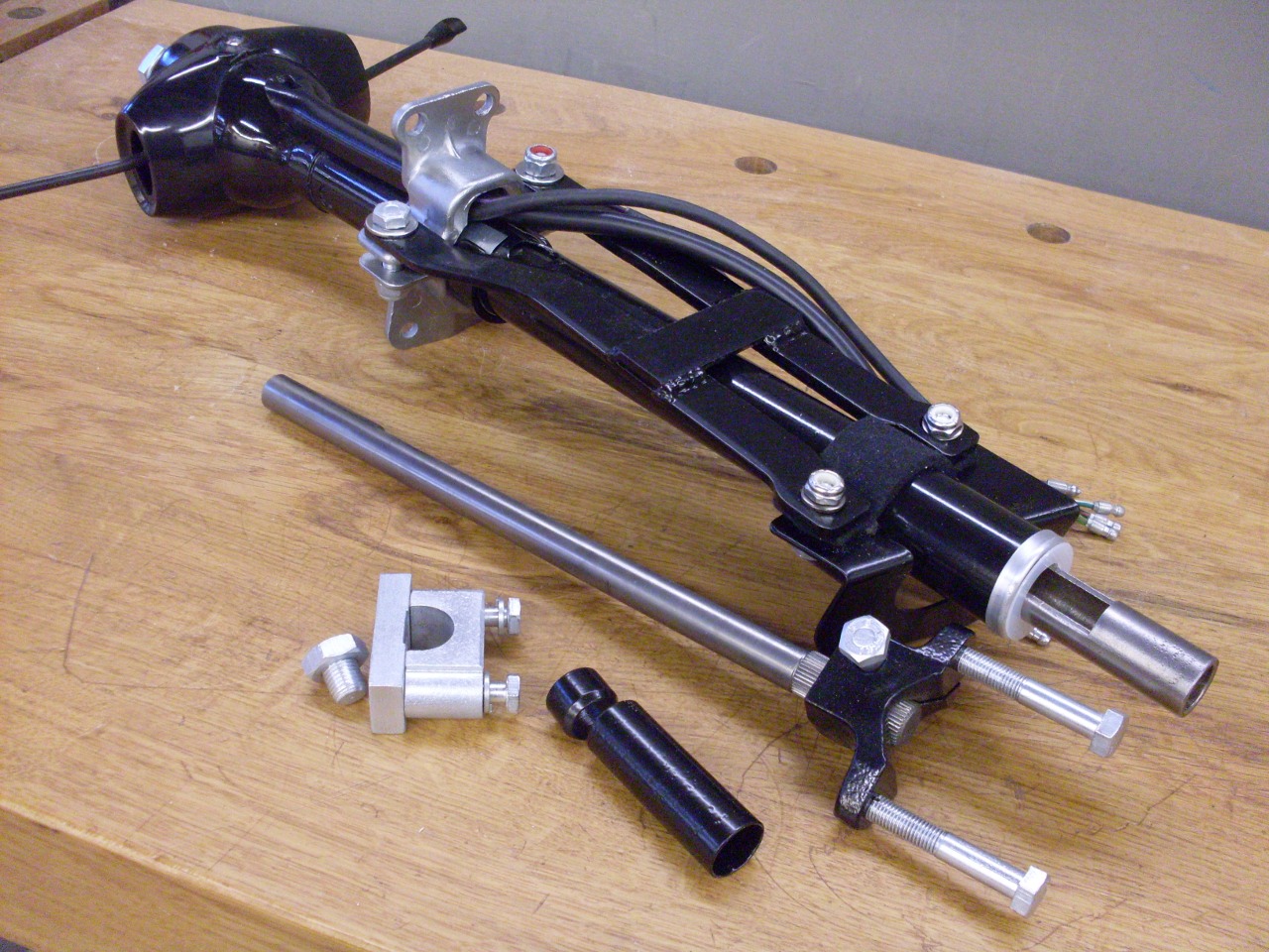
At
the lower end of the column, there is a smaller shaft that fits inside
the column shaft. This is the shaft that connects to the
intermediate shaft that in turn connects to the rack and pinion box.
The inner shaft can telescope inside the column shaft, but is
located by a couple of tubular distance pieces, and held in position by
an adjustable clamp. This is no doubt part of the
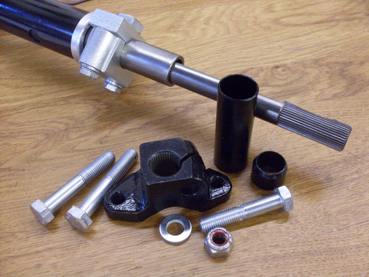
energy-absorbing design of the assembly. In a front
crash, the inner shaft can collapse the distance pieces (the
larger one can ride up over the smaller one, which is beveled at their
intersection), and slide into the column shaft against the clamp
friction. I believe the weak aluminum column may also be designed
to crush, absorbing more energy.
Most of the parts were either plated or powder coated
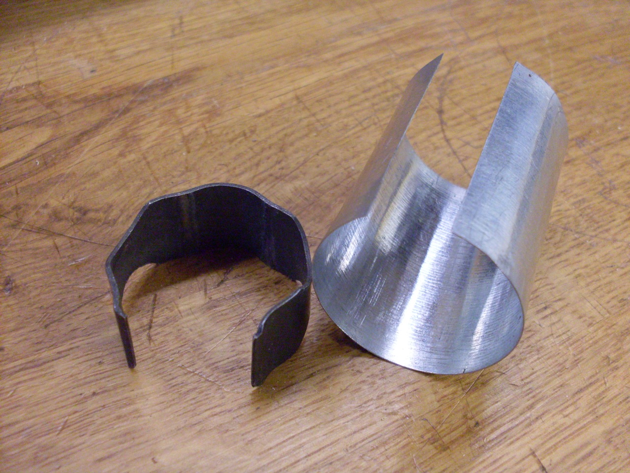
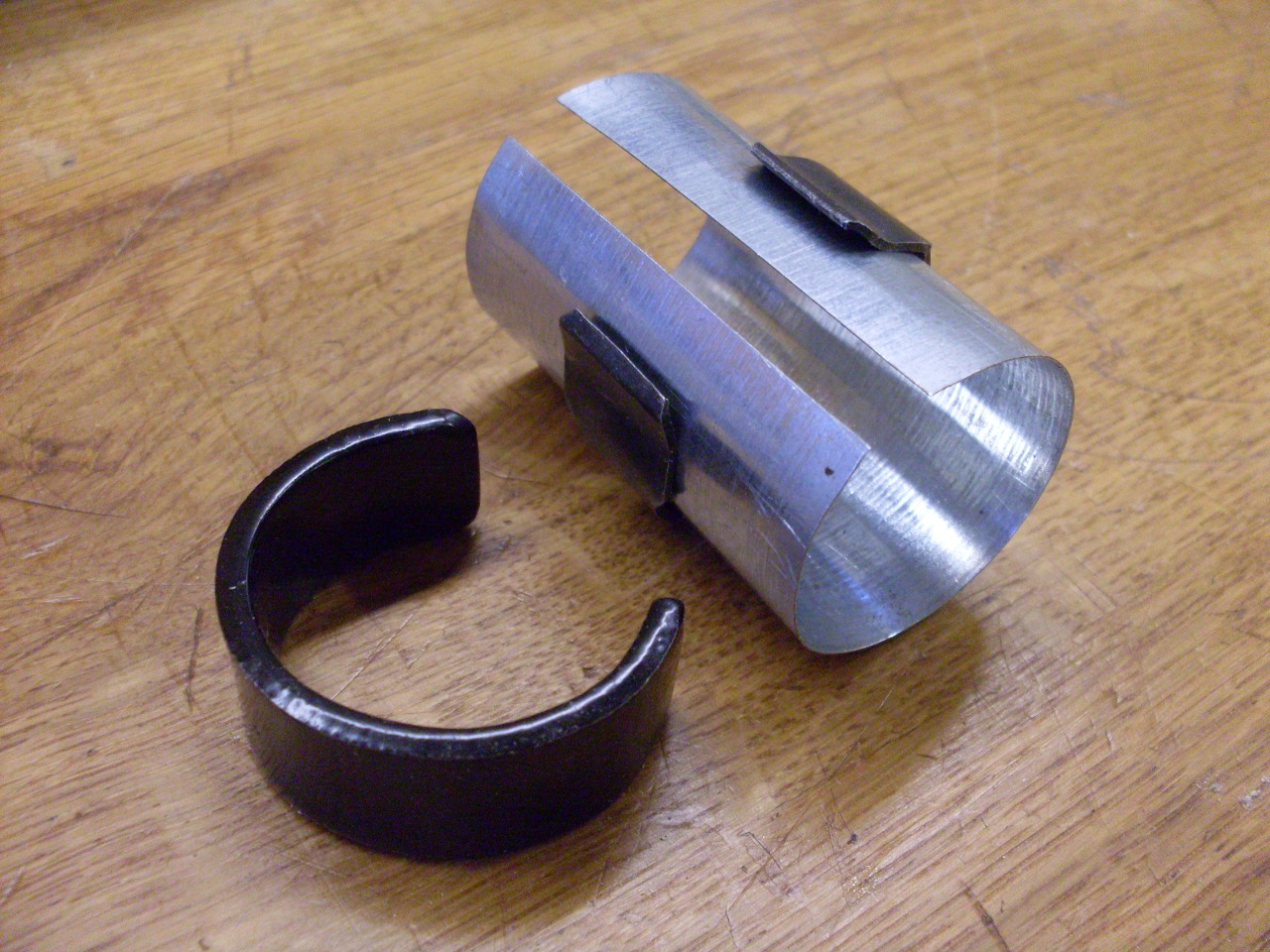
To
address the damage done to the column by the upper clamp, I fashioned a
thin sheet steel pad for the clamp to bear on. It's harder
surface should prevent gouging the soft column. The spring clip
was a little deformed and a loose fit on the column. I had to
coax it back to a shape that gripped the column better.
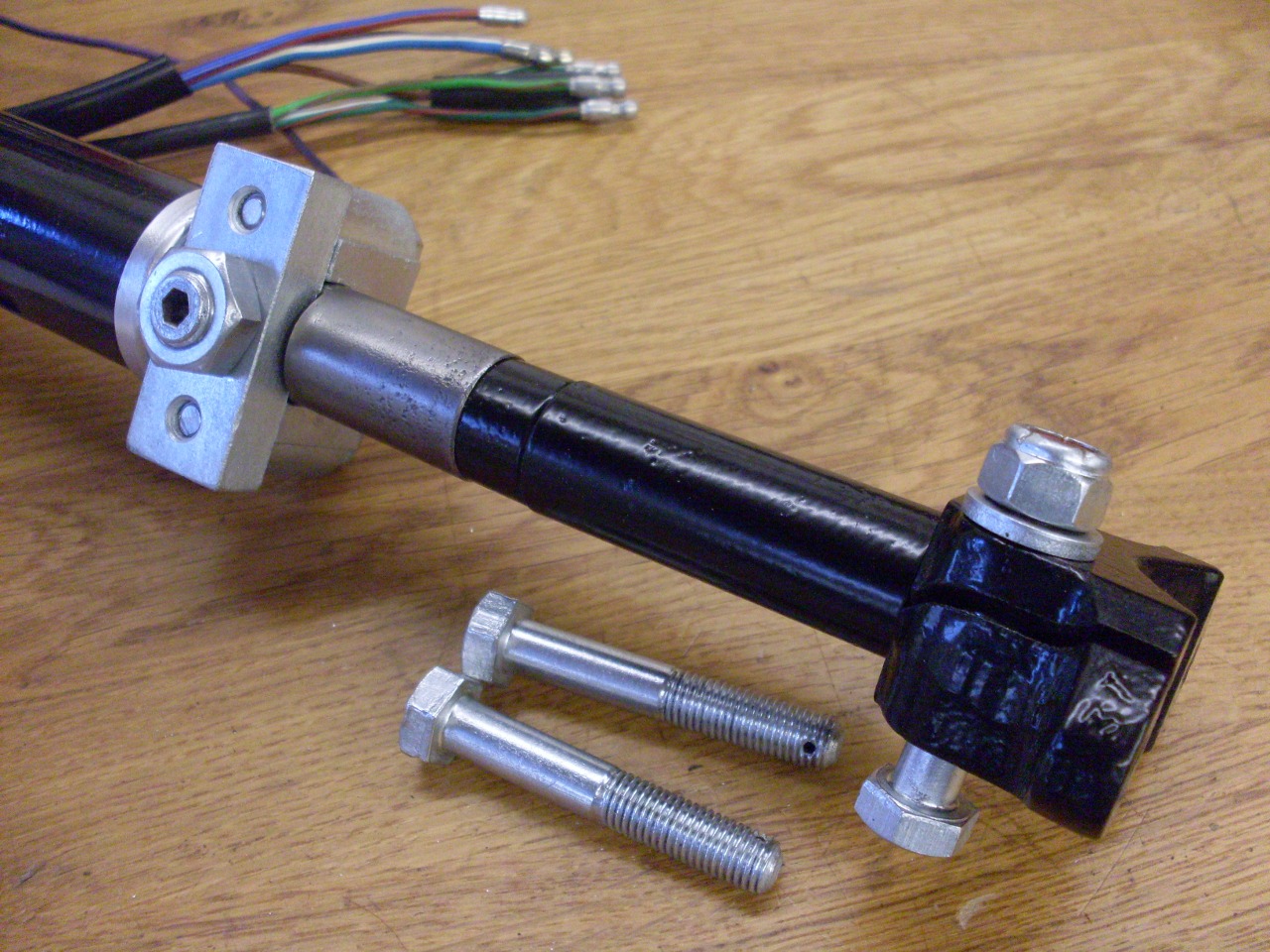
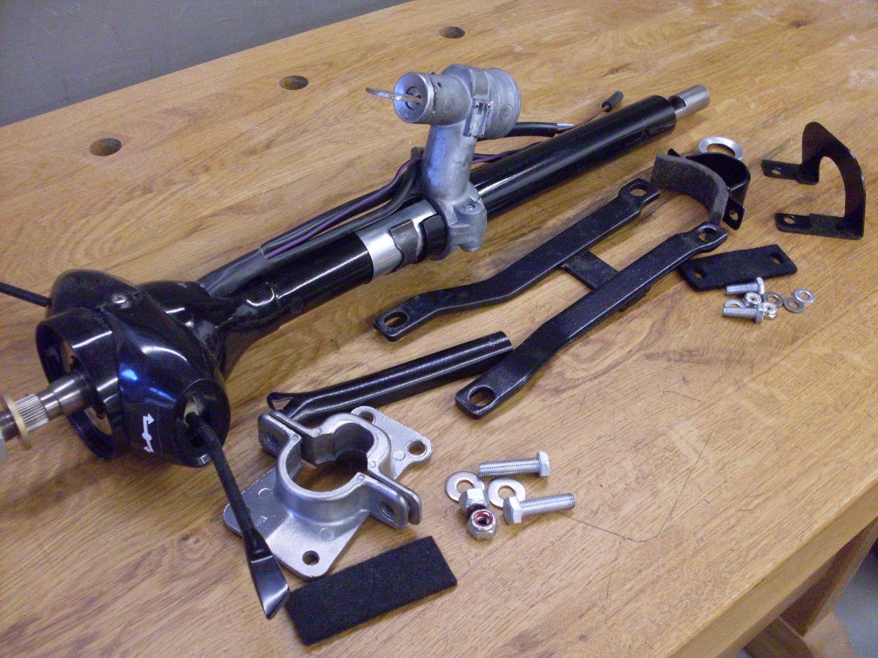
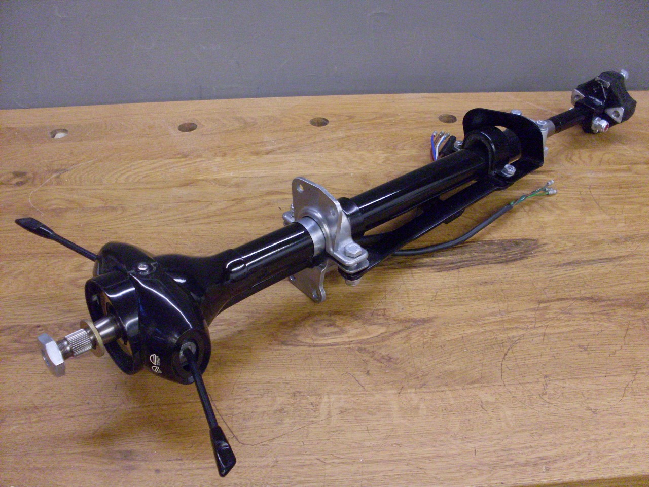
Here
are most of the pieces for the column mounting brackets, The
column is isolated from most of its mountings by felt strips. I
mounted the ignition switch/steering lock assembly in order to check
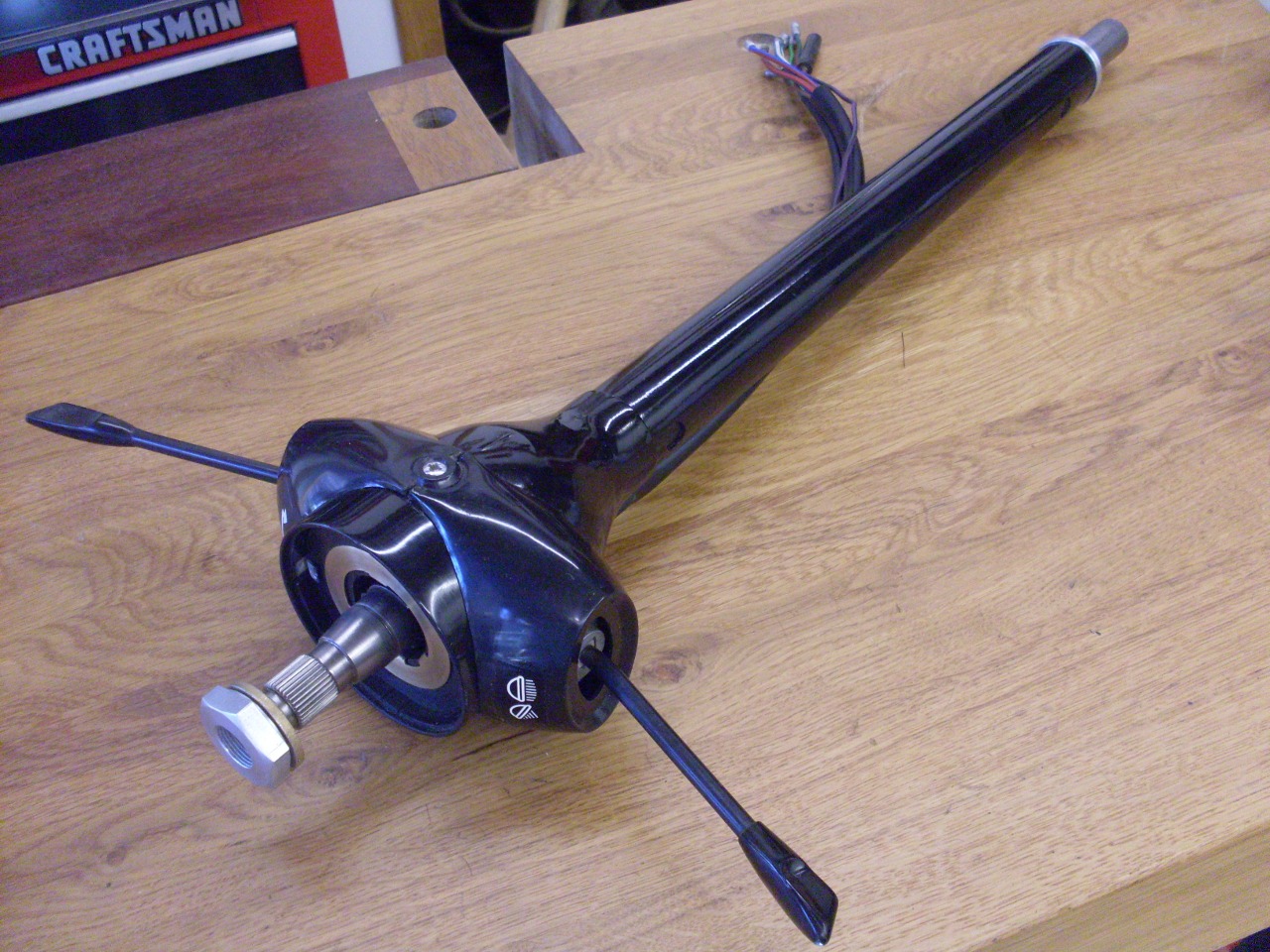
fit, but it's a mess and will be a project of its own.
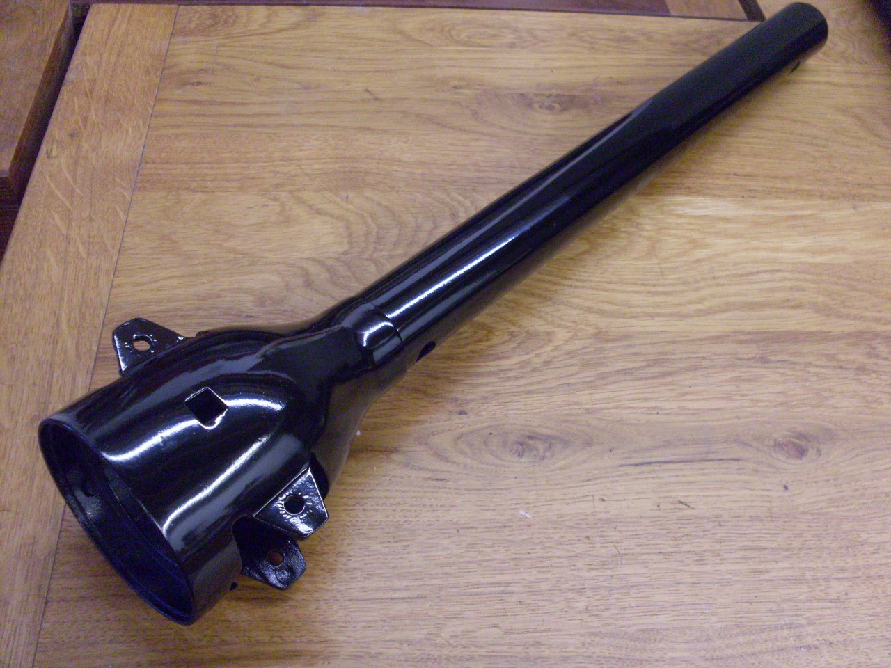
This dude is about done and ready to install...some day.
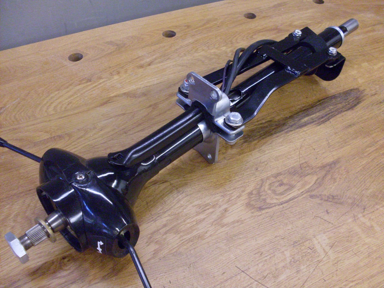
This
was one of the cheaper rebuild projects on the car so far--new decals
and felt strips, a new nylon washer at the bottom of the column, and
various consumables. Probably less than $20.
Comments to Ed at elhollin1@yahoo.com
To my other TR6 pages.