To my other TR6 pages
December 17, 2014
[Click the pics for a bigger view]
Drive Shaft
The
TR6 drive shaft (or propeller shaft) is a pretty standard item.
It has a flange connected directly to a universal
joint at each end, and a sliding spline joint in between.
This arrangement accommodates the changing alignment between the
transmission output shaft and the differential input shaft. All
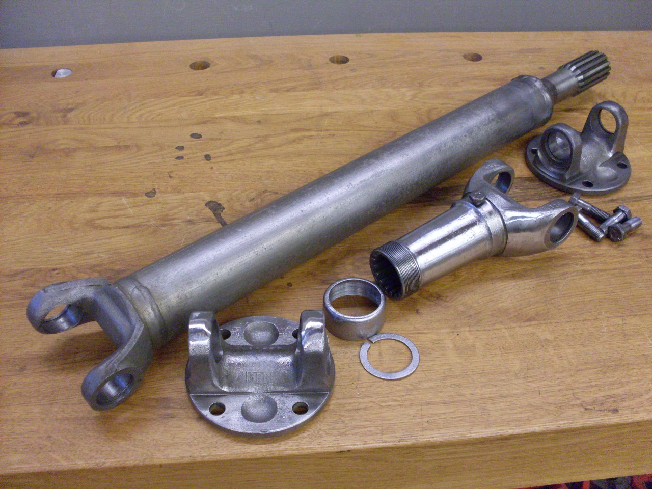
the parts of my drive shaft were dirty and rusty. This is after
pushing out the U joints.

After some cleanup and derusting:
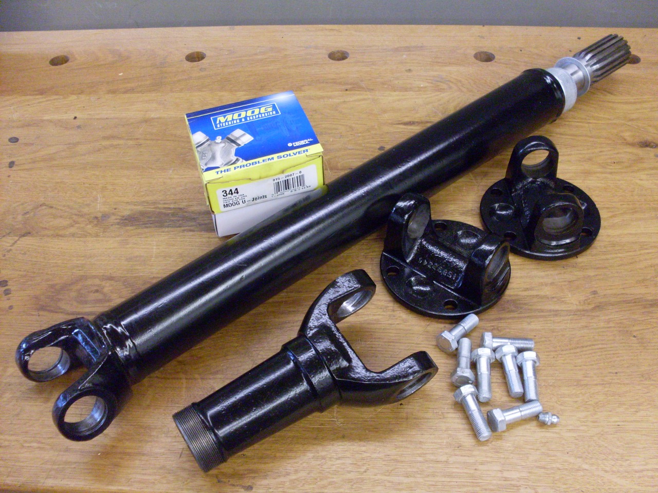
After powder coating. The main shaft is too big for my small oven, so it got a couple of coats of POR15.
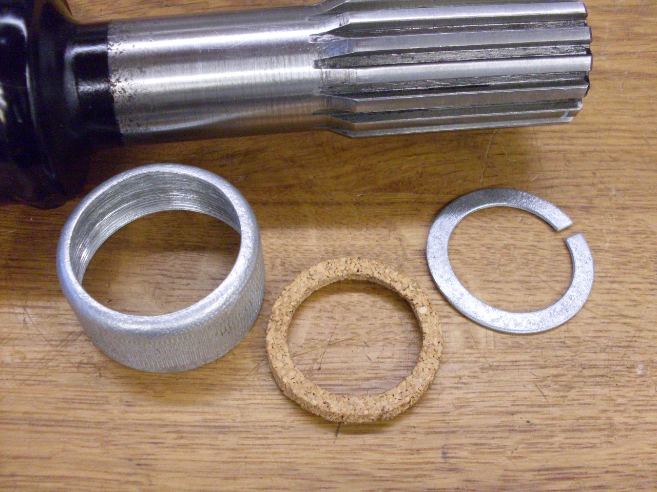
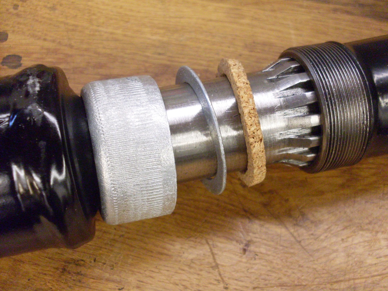
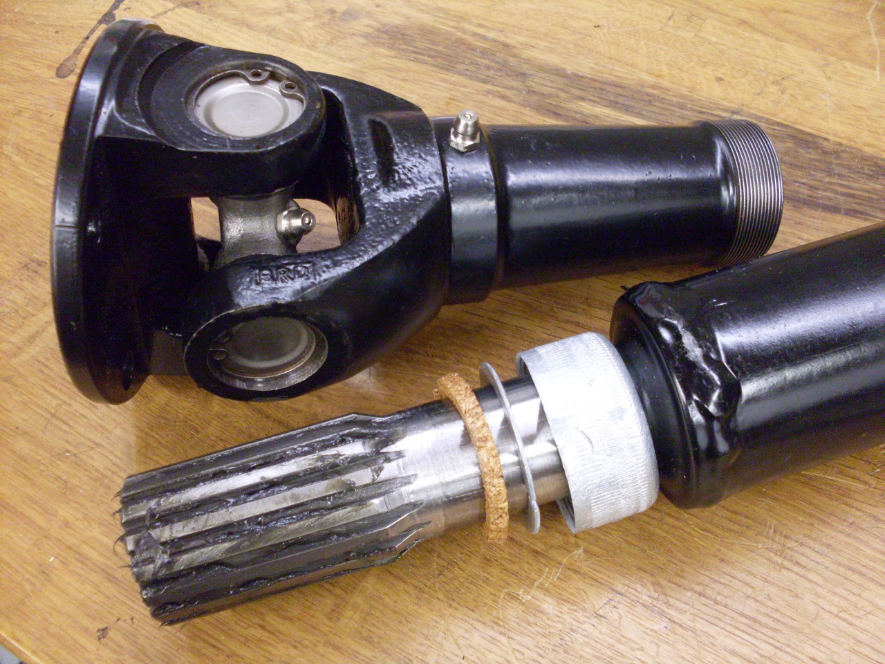
The
sliding spline has a cork seal to keep dirt out. It was hard and
brittle, and came out in small pieces. As far as I can tell, it
isn't available anywhere, so I fashioned one from some cork sheet.
The steel split washer and the cap were re-plated.
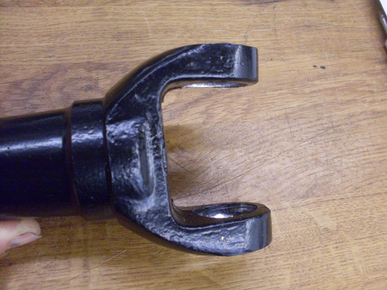
Here
is where the story takes a grim turn. Any time someone uses a
powerful tool like a hydraulic press to move something, there is a real
potential for unintentional carnage. Installing U joint bearing
caps is a relatively routine process, but occasionally something goes
awry. I was pressing one of the caps into the sliding yoke when
something apparently got cockeyed in a direction I didn't see.
When I should have stopped and investigated the reluctance of the
cap to go into the bore, I kept pouring on the tons, believing the cap
would right itself. The sad result was a bent ear on the yoke.
A disappointing
Internet search revealed that no one was selling just the yoke, and
that everyone who was selling a complete drive shaft apparently
believed it was made of platinum.
This made me think a
little harder about undoing what I had done to my yoke. Within
limits, bending is usually a reversible process, so maybe I could
unbend what I had bent. Careful measurement showed that the
extreme end of one yoke ear was bent in by about 0.080". The
deformation extended down only to about the center line of the bore.
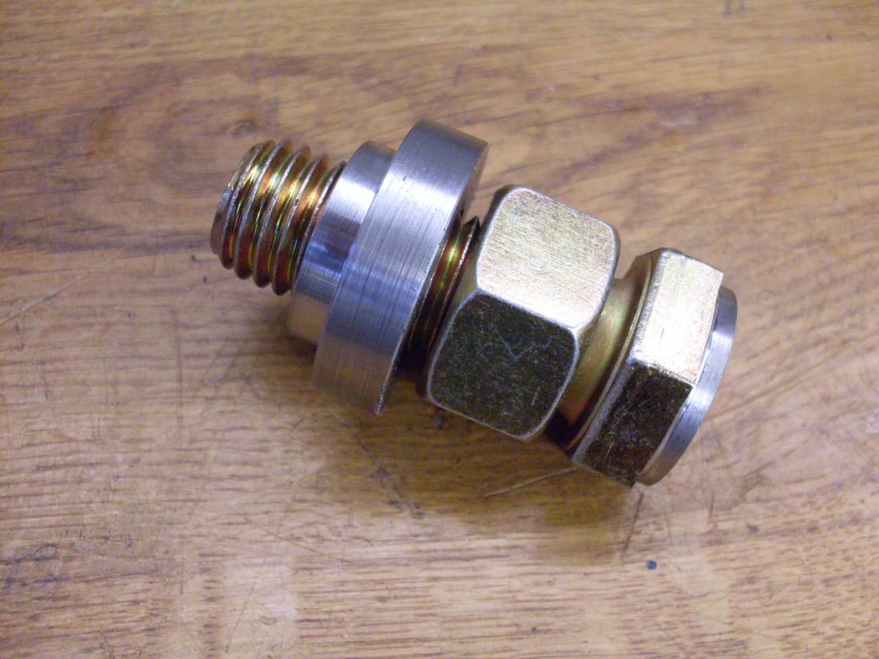
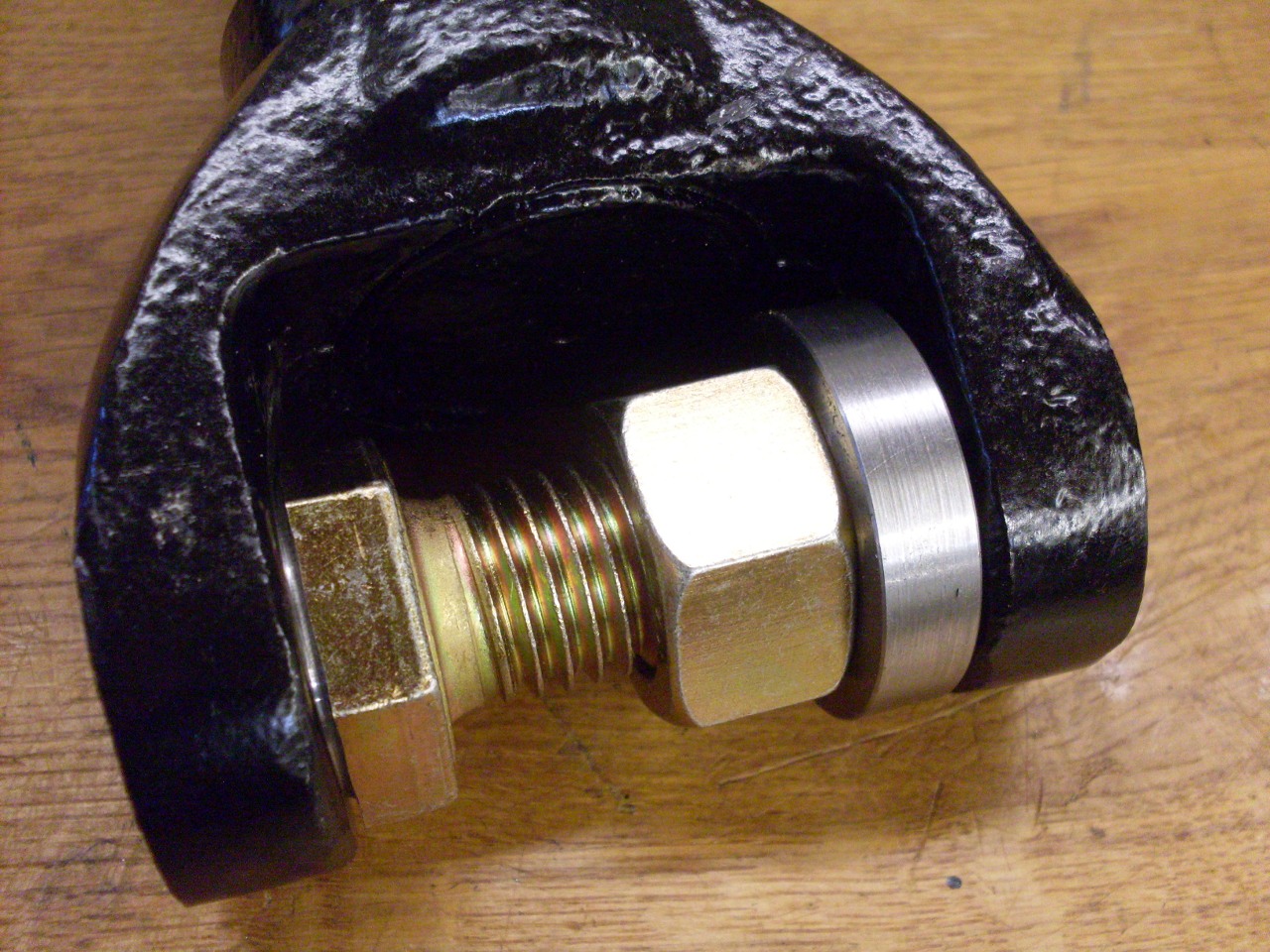
Another Internet search revealed that some people have
successfully repaired this kind of damage, and I adapted one of the
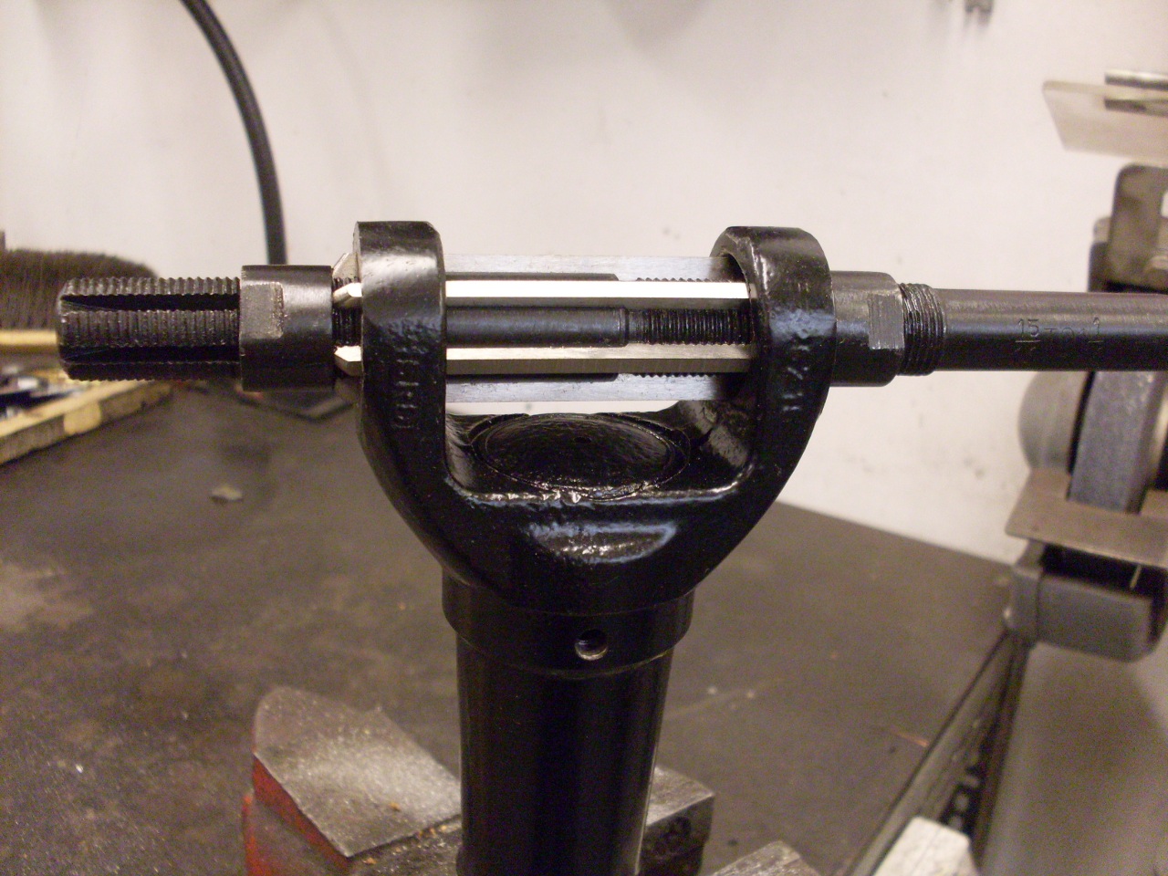
methods to fit my situation. The head of a 3/4" Grade 8 bolt was
modified so that it would slip into one of the cap bores, which would
keep it centered. A nut on the bolt presses on a stepped collar
that fits into the other yoke bore. This arrangement can apply an
enormous amount of pressure--probably as much as my press. The
little shim in the last pic was inserted to apply all the pressure at
the outer end of the bent ear, since that's where the deformation was
the greatest.


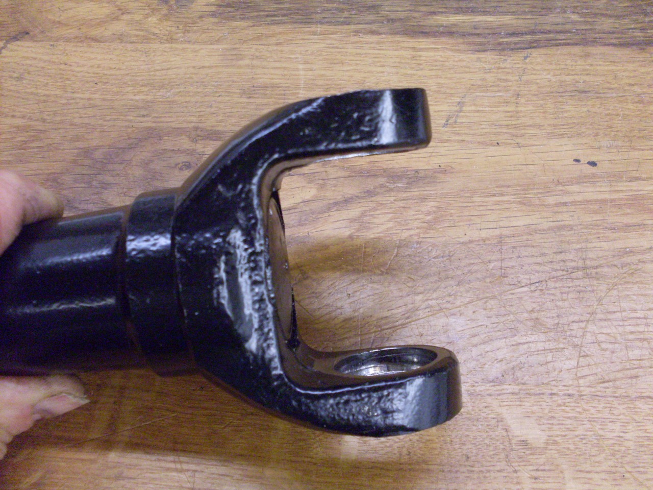
I
went through several cycles of pushing and measuring, and the ear was
slowly moving. I was able to get the ear within a few thousandths
of the correct dimension. I was prepared to use heat, but didn't need to.
After
this success, I noticed that the cocked cap had also left its mark
inside its bore. There was a small ridge of upset metal in
the bore. I was also worried about some lingering distortion of
the bore, so I decided to carefully ream the bores to ensure that they
were round, but also that they were colinear. I used a
cheap adjustable hand reamer for this. Its blades happend to be
just long enough to span both bores. I opened the reamer just
enough to clean up the ridge.
Of
course the danger here is that one or both bores will get too big, and
the bearing caps will be too loose. Luckily, this wasn't the
case, and both caps were still a nice firm press fit.
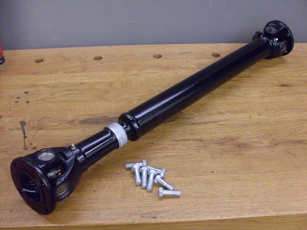
The
final shaft, ready for install. When assembling the sliding
joint, it's important to get the phasing of the U joints correct.
A single U joint can produce a slight oscillation in speed which
can be canceled by a second U joint if the relative orientation is
correct.
Comments to: elhollin1@yahoo.com
To my other TR6 pages