To my other TR6 pages
September 20, 2014
Rear Half Axles and Hubs
[Click the pics for a larger view.]
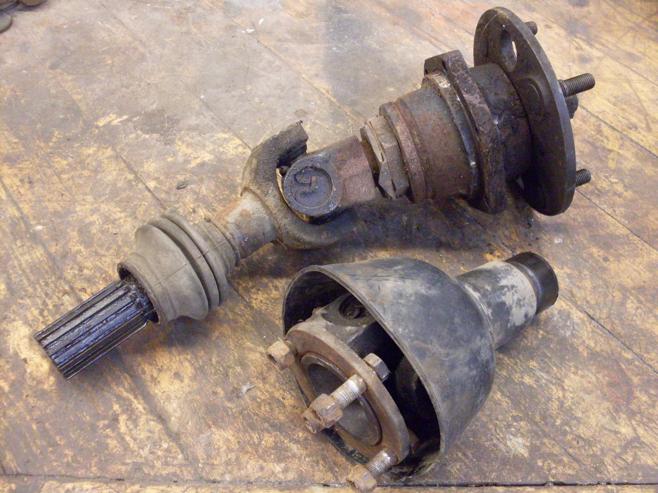
The
TR6 uses a semi trailing arm rear suspension where each arm carries a
wheel hub connected to the frame mounted differential by a "half axle".
The half axle must accomodate the swing of the trailing arm by
changing its length and the angles between the differential and hub
flanges. It does this by using a pair of universal joints and a
sliding spline.
My
axles were apparently in decent shape, with no obvious problems.
The hubs and joints all had smooth action. On the other
hand, they were old, and had a fair number of miles on them. In
keeping with the spirit of the rest of the project, I decided to
rebuild the shafts and hubs.

This
is a job that is widely considered not to be a DIY undertaking, which
unfortunately comes across as a dare to me. In the end, I'd have
to consider this one of the more difficult jobs on the car so far, but
not out of reach for someone with moderate mechanical skills. The
manuals list a number of required special tools which probably aren't
available any more, but I found that there are ways to inprovise around
them.
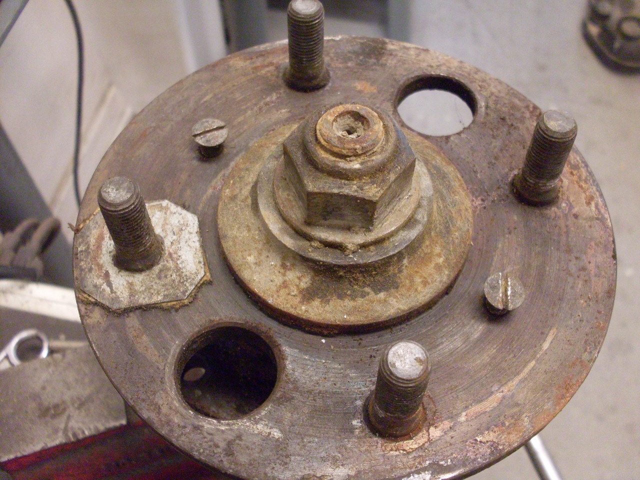
I
found a note written by me in the back of my Haines manual, dated 1980.
It said that I had replaced the wheel bearings in the right
hub, but that I couldn't get the left one apart, and had slghtly bent
the wheel flange in the attempt (probably with a two- or three-arrm
wheel puller). This was likely the reason behind the shim on one
of the wheel studs.
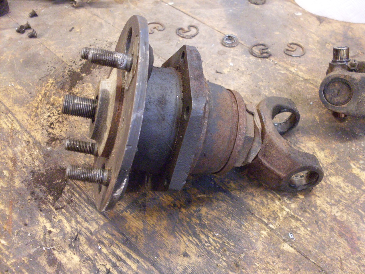
Separating
the U joints is a pretty routine job, but getting into the wheel
bearing housing takes a little more determination. The outer axle
shaft has to be separated from the wheel hub, to which it has been
mated for forty years with a big-ass nut torqued to 100 foot-pounds.
Since there isn't an easy way to provide support to the back of
the wheel hub, a hydraulic press normally isn't used for this.
It's tempting to break out the wheel puller like I did back in
'80, but as I found, the edge of the wheel hub flange isn't beefy
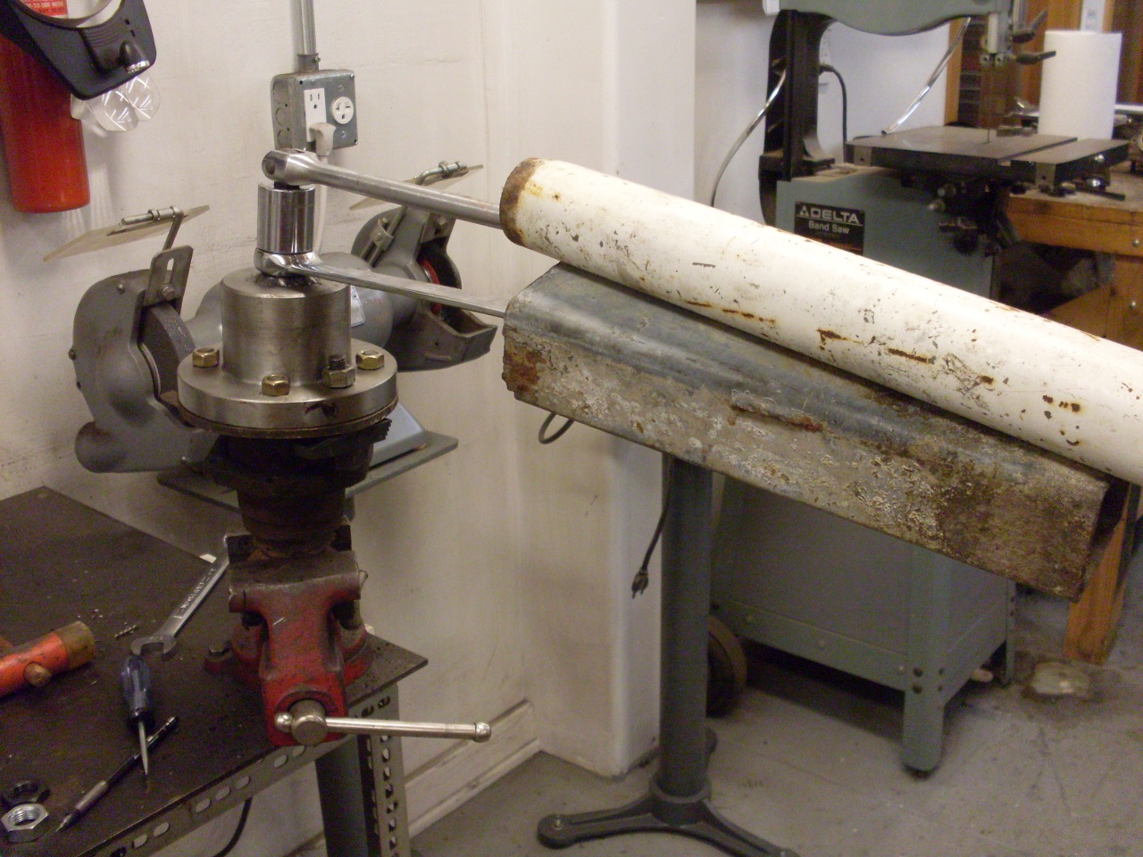
enough to resist the necessary force. Here is where one of
Triumph's special tools comes in. It is just a hefty wheel puller
designed to pull on the wheel studs while pushing down on the axle
shaft. Plenty of people have made their own versions of the
special tool, so I did, too.
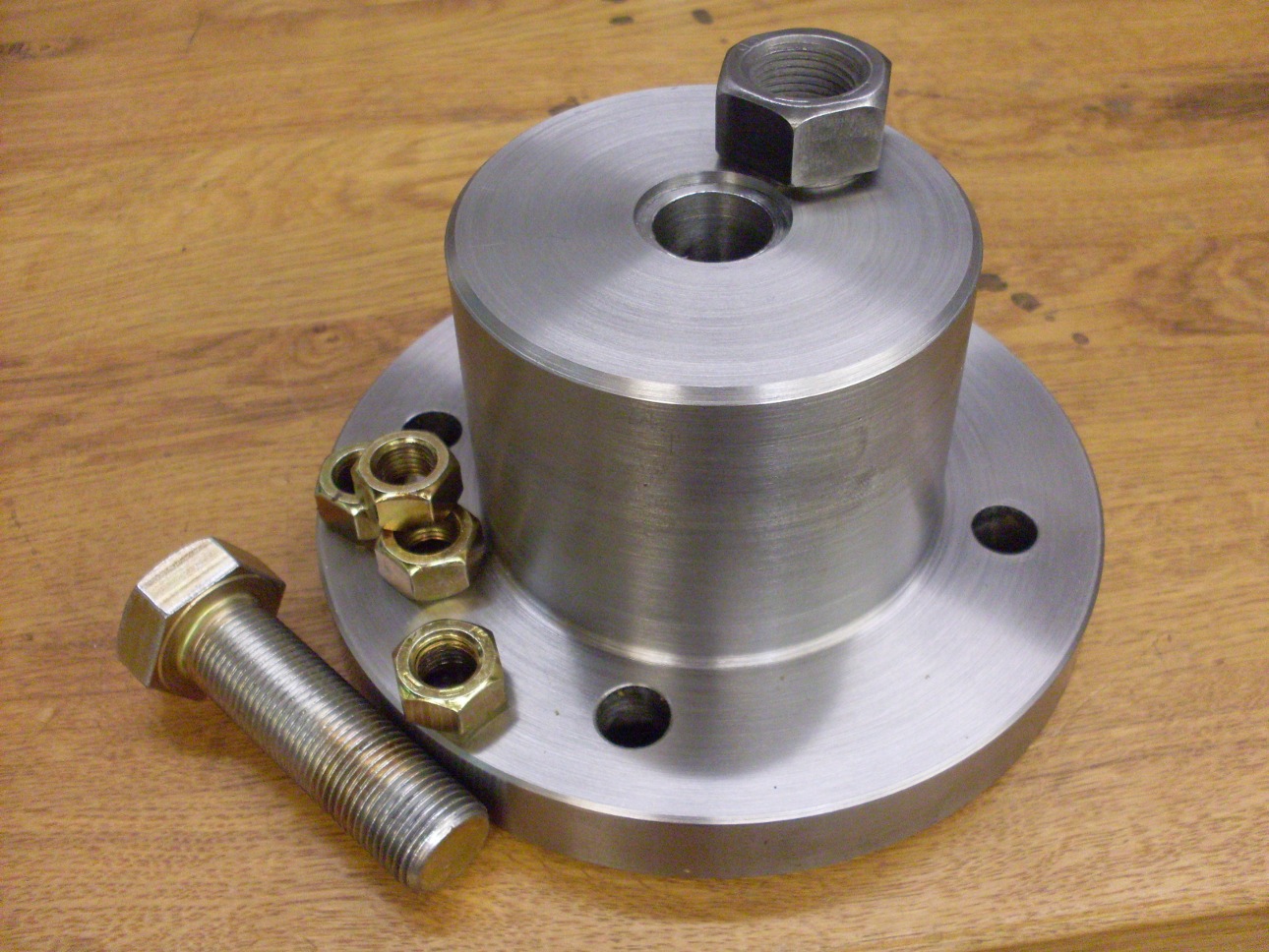
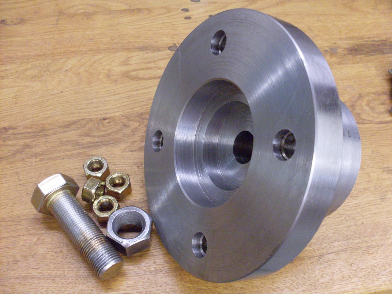
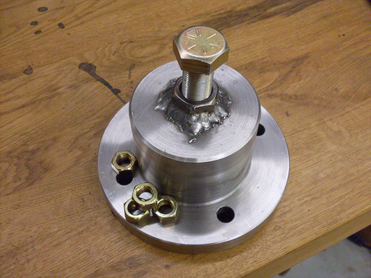
Starting with a hunk of 6-inch round and some grade 8 hardware, I fashioned a serious puller. It weighs nearly 12 pounds.
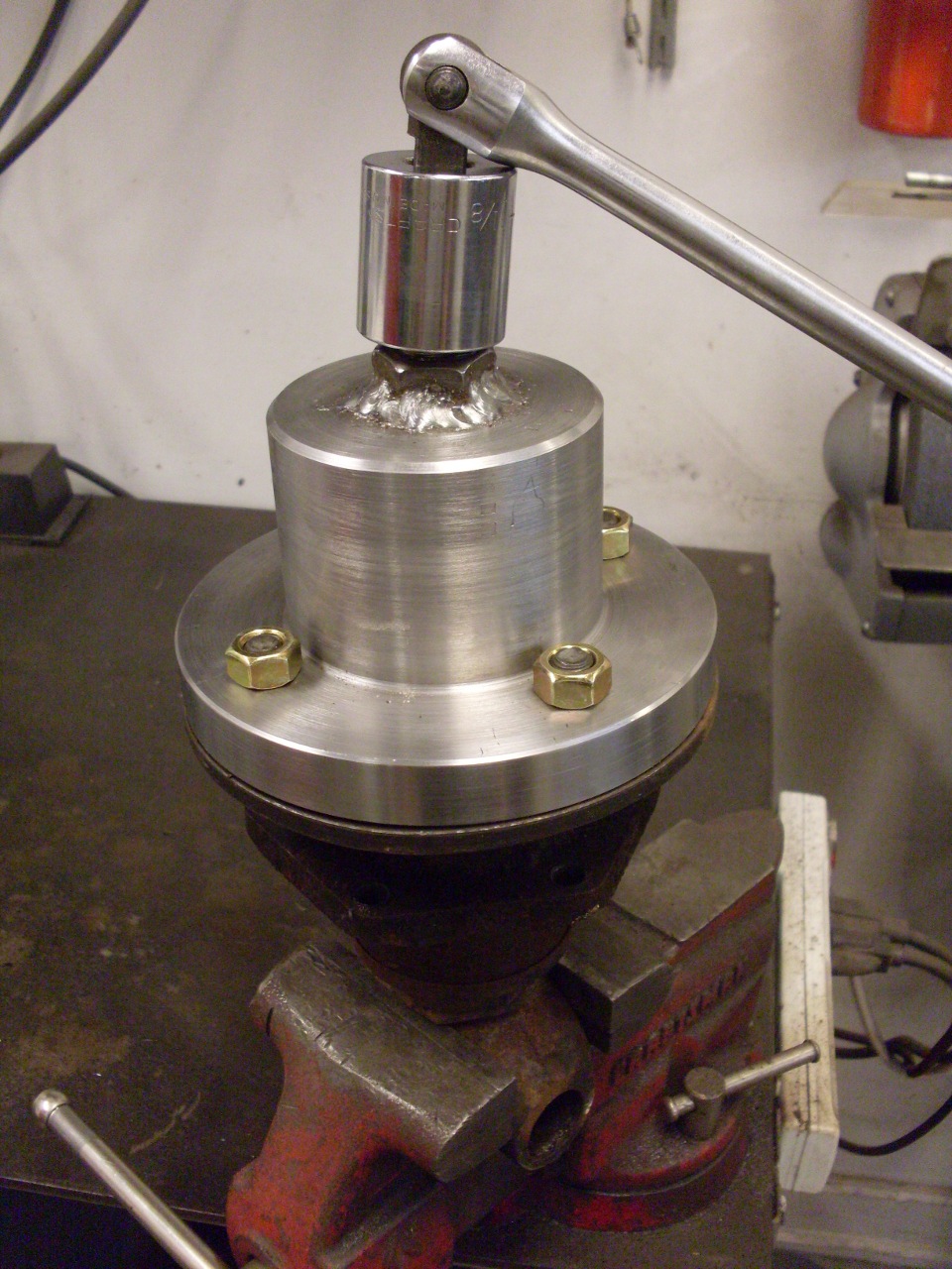
While
the right hub came apart relatively easily, the left one--the one I
had trouble with 34 years ago--was being difficult. Torquing
on the puller bolt with a three foot cheater bar, I could see the wheel
hub flange starting to distort. I've read various places the
opinion that a thick flange on the puller is necessary to support the
thin flange on the wheel hub to keep it from bending. I just
don't see this since no matter how thick the puller flange, the force
is still concentrated on the four stud bolts. I don't believe a
thicker puller flange prevents bending at all.
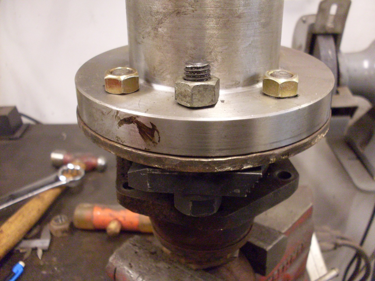
One
thing I did do to provide more support to the thin hub flange is to
drill two more holes in the puller flange. Using the two large
holes in the hub flange, I could place a thick steel bar under the
flange and snug it up to the puller flange. This does give a lot
more support, and reduced the distortion greatly.
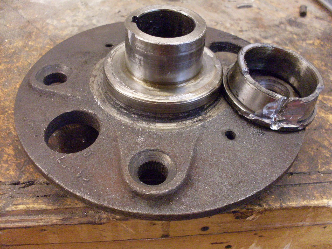
So, with enough heat, cheater bars, and swearing, the hub finally gave up.
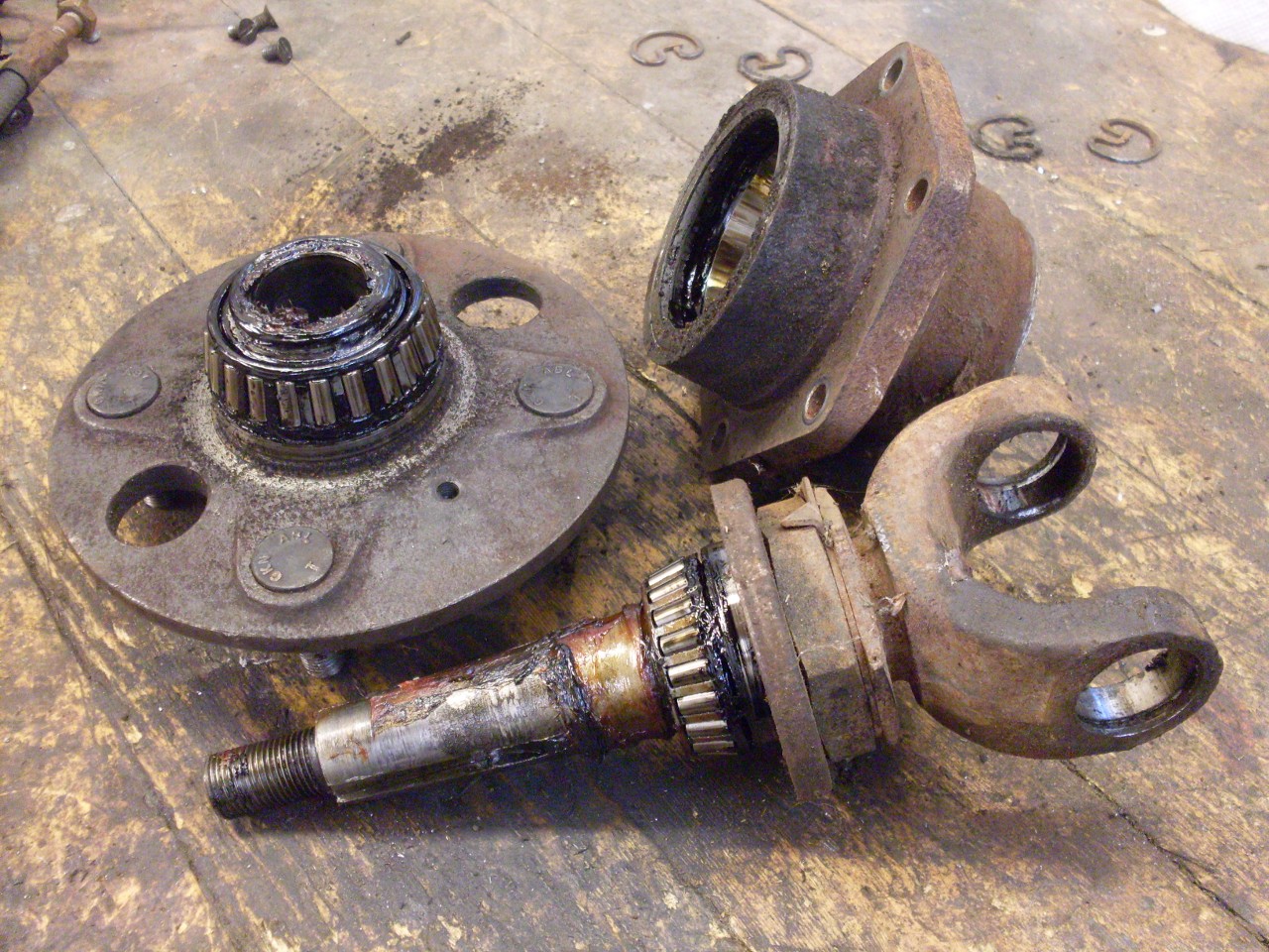
That same hub, in an act of pure spite, also made me cut off the inner bearing race.
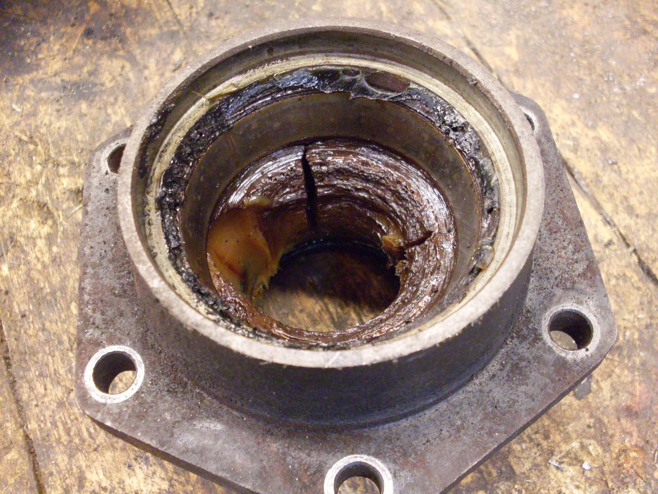
As
an aside, I've read a number of discussions about the amount of grease
that should be put in a hub--just a little, or pack it full? Here
is what was in the left hub, not opened since it left the factory.
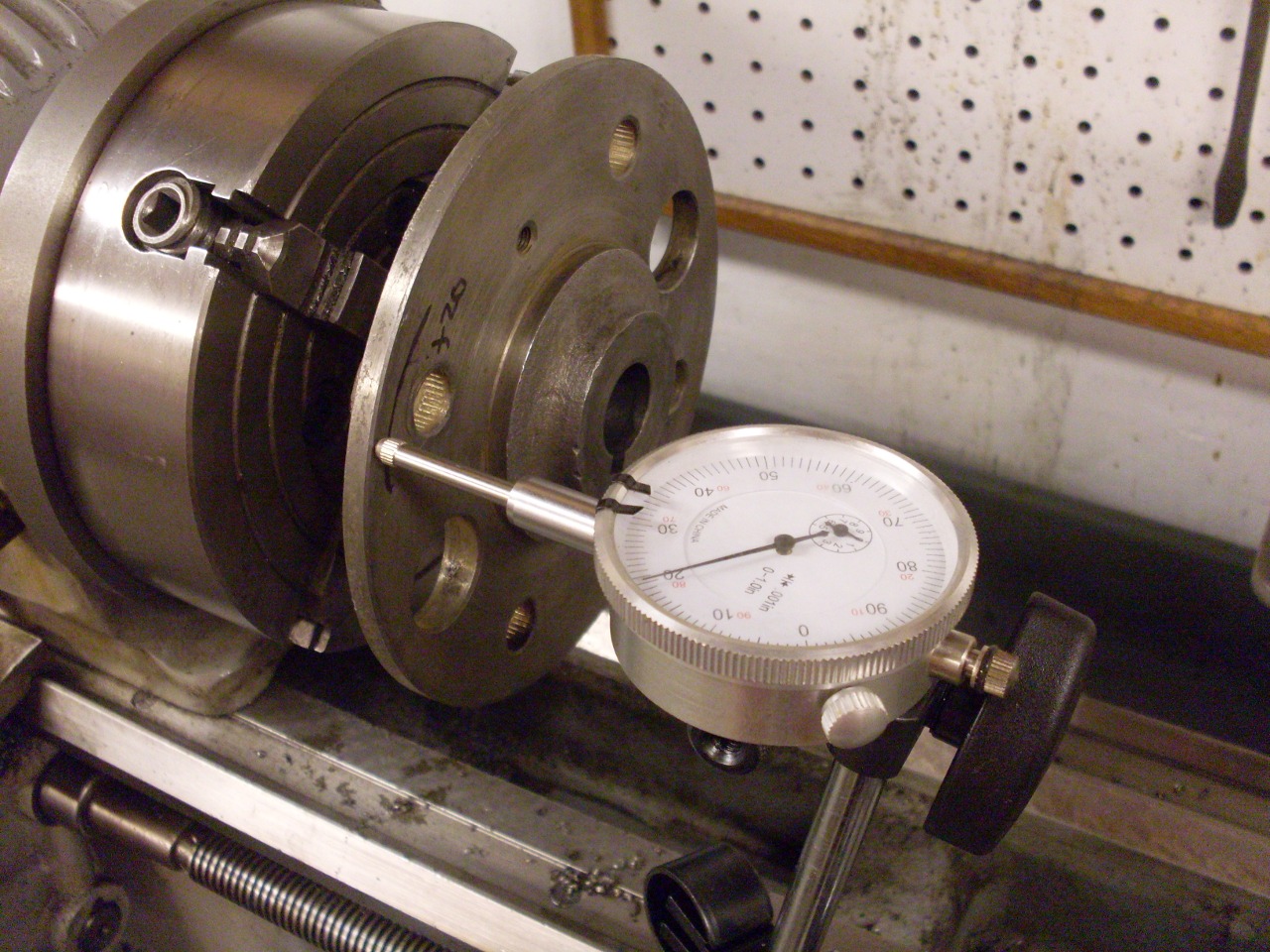
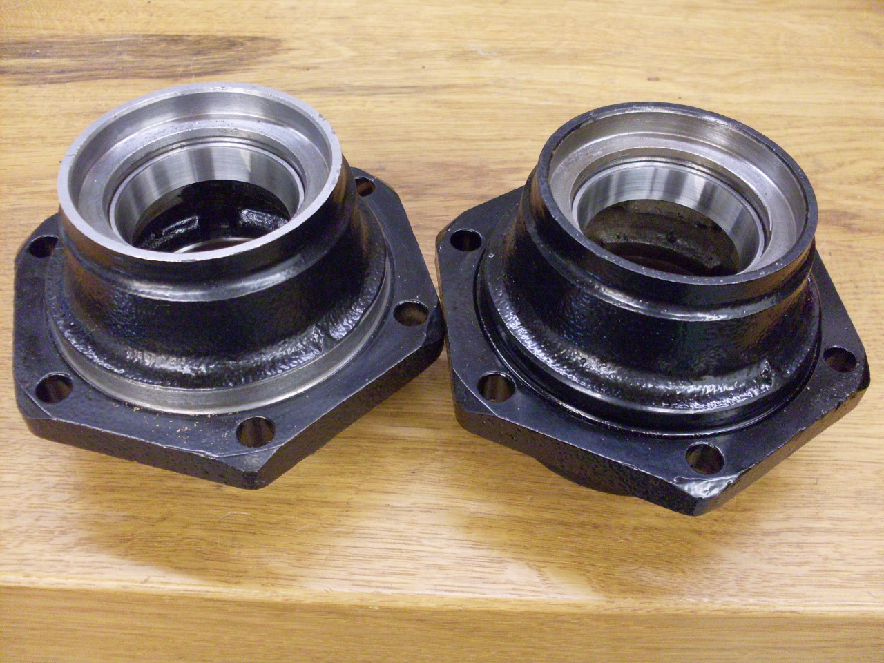
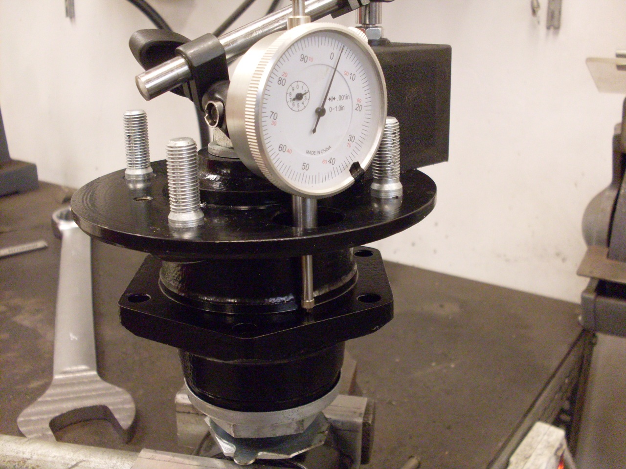
I
was concerned about all the violence done to the wheel hub flanges, so
I checked them for trueness. The right one had a variation
of about 0.020", but the disagreeable left one had a difference of
0.053" from high to low.
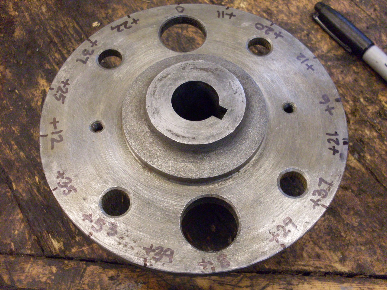
I
played with the bad one on the press, trying to reverse the bending
caused by
the pullers, but couldn't get it much better than about 0.030".
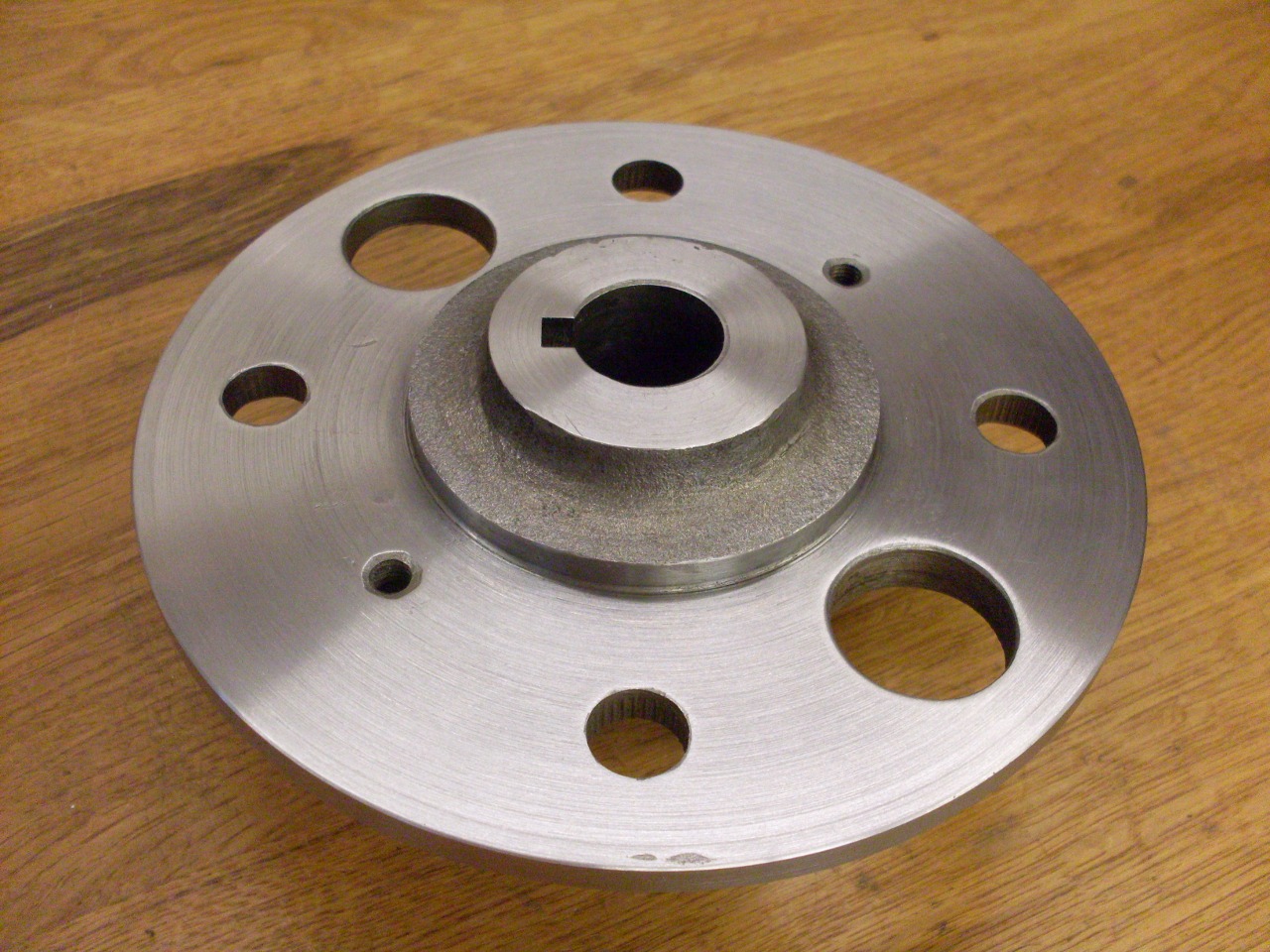
These errors get magnified by the larger diameters of the brake
drum and wheel, so I decided to flatten the flange surfaces on the
lathe. These flanges are already a little on the thin side, so I
wanted to take as little off as possible. Since I just needed the
flanges to be flat in the areas around the wheel studs, I was able to
true up the flanges by removing only about 0.015".
Powder
coated the larger pieces, zinc plated the hardware, and got new
bearings and U joints, which are common types and easy to find. I
try to buy these kinds of items at local industrial suppliers because I
can know what brand I'm getting before I pay for them.
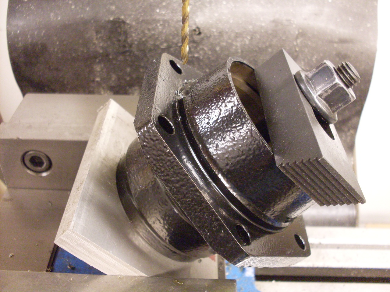
Now
here is a mod that I'm not sure is worth it or not. These rear
hubs are not like the front ones that are easy to get into to pack the
bearings. Since it is such a chore to crack open the rear hubs,
they rarely ever get lubricated. To address this, I decided
to add a provision for adding grease to the interior of the bearing
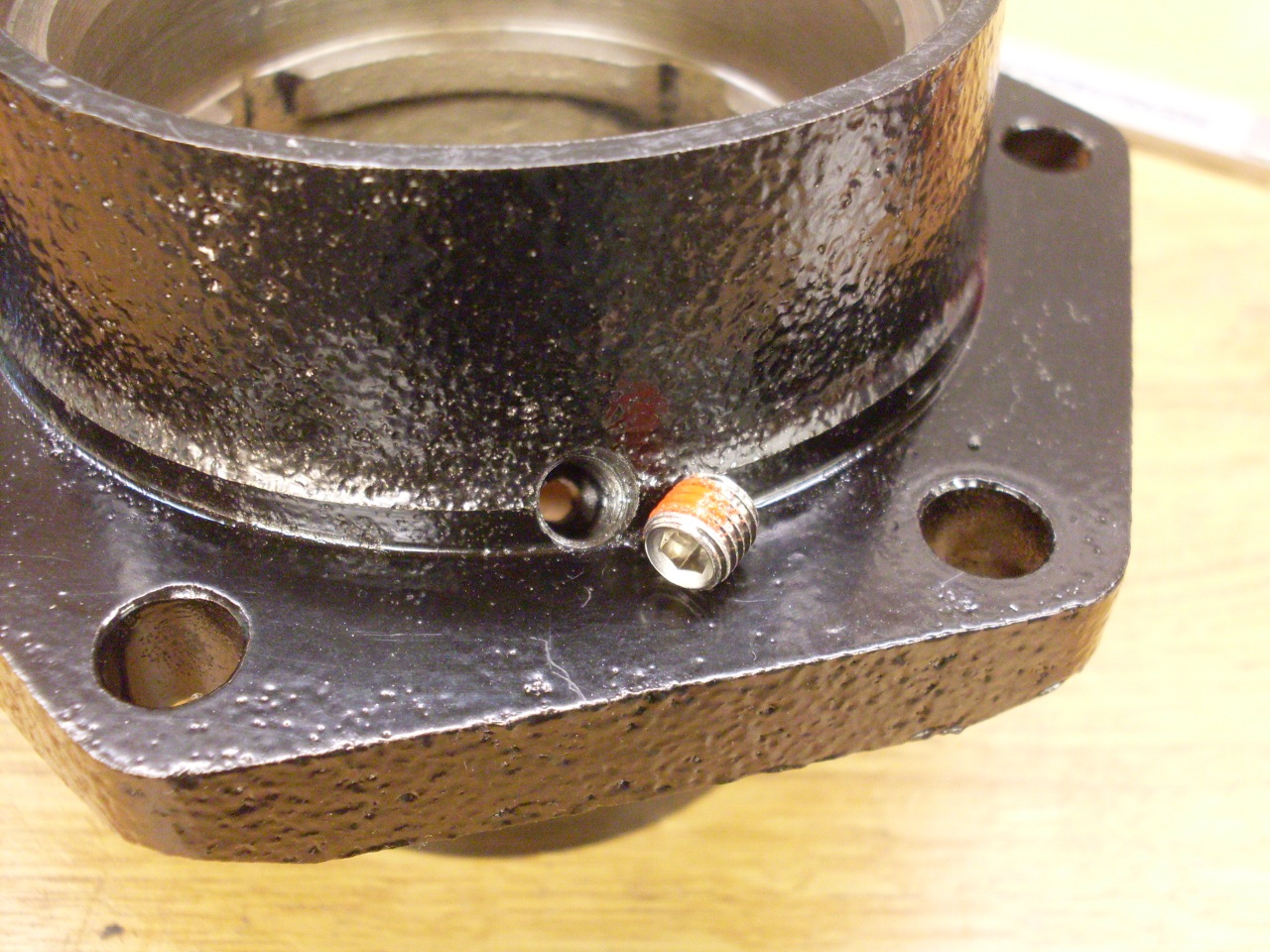
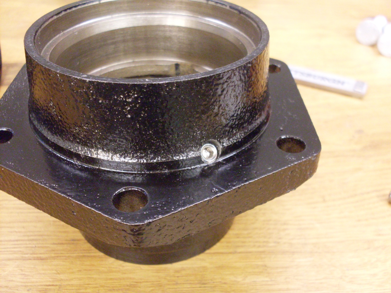
housing. I drilled a 1/8" hole at a 45 degree angle from the
outside into the cavity between the bearings. I then drilled and
tapped the top 3/8" for 1/4-28. This will accept a grease zerk
fitting, but I installed lock-type allen set screws as plugs.

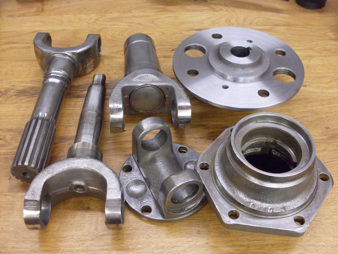
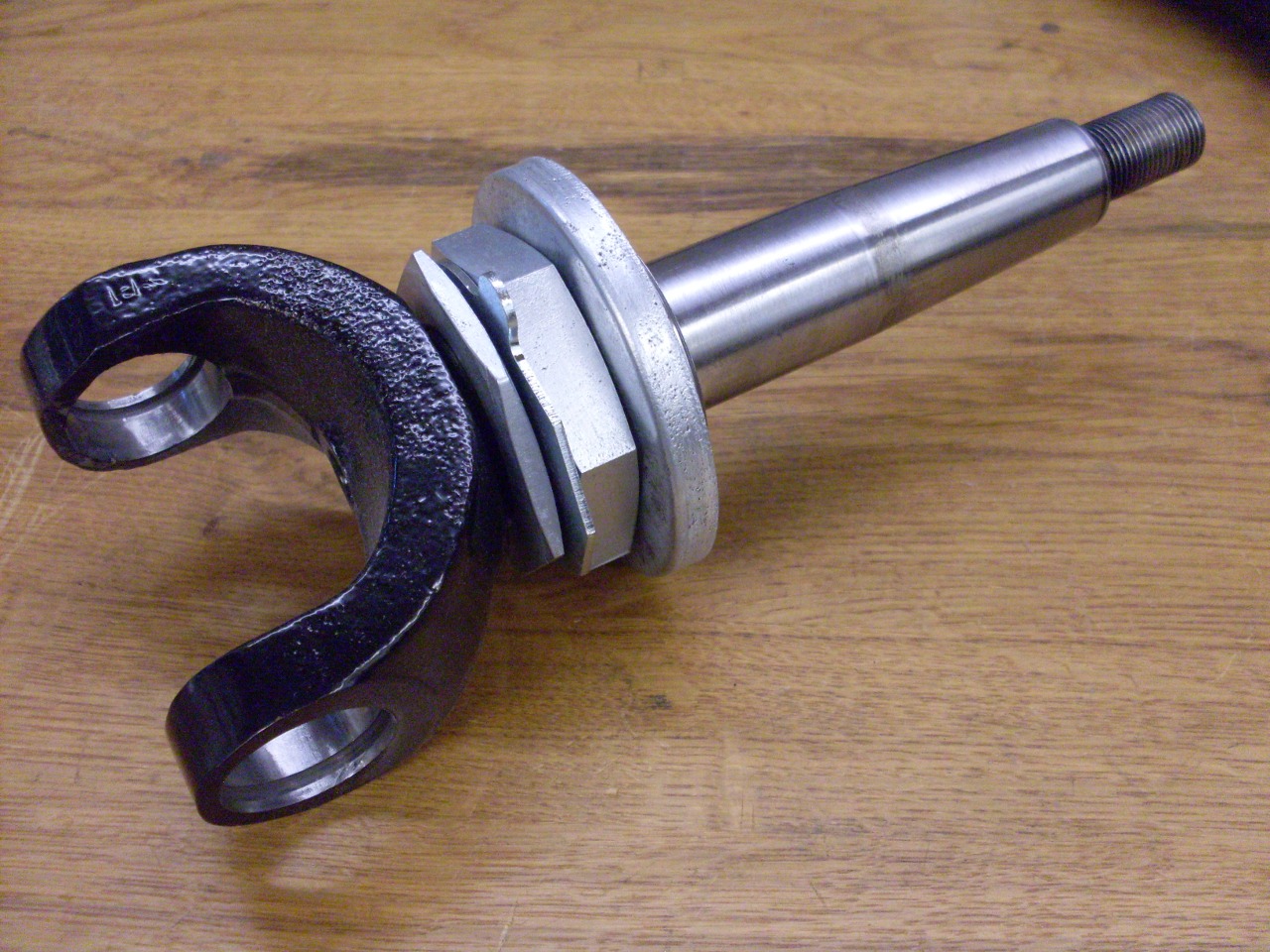
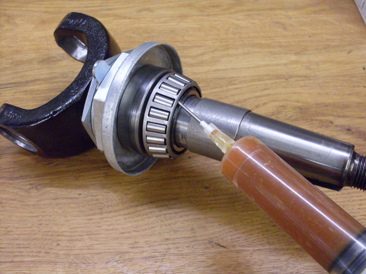
Putting
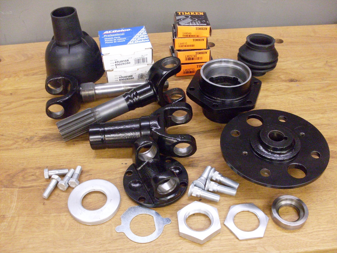
everything back together now. Assembled the adjusting hardware on
the outer axle, then pushed on the new bearings with shop made adapters.
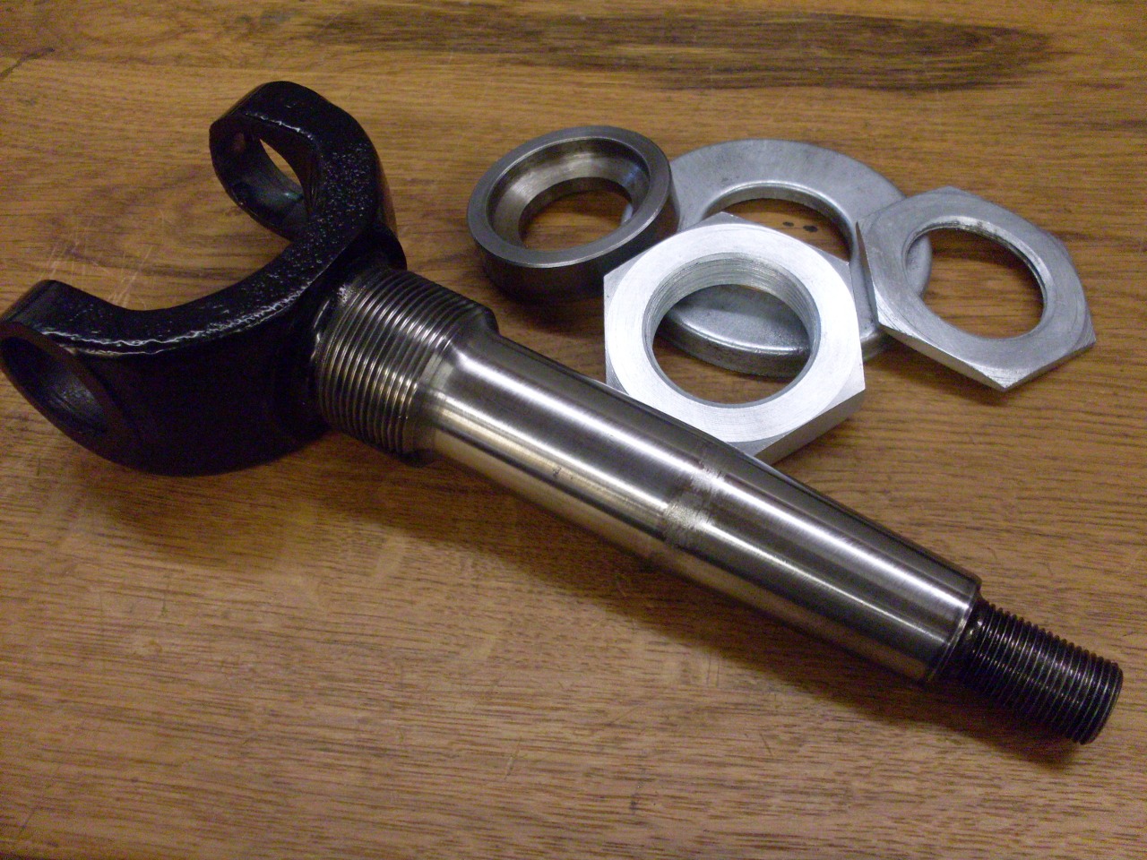
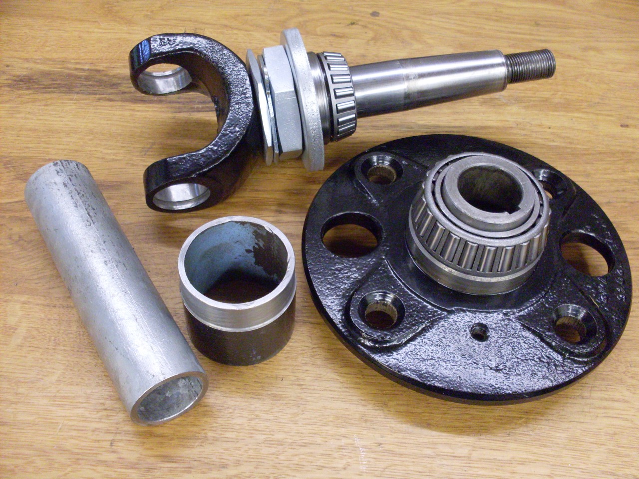
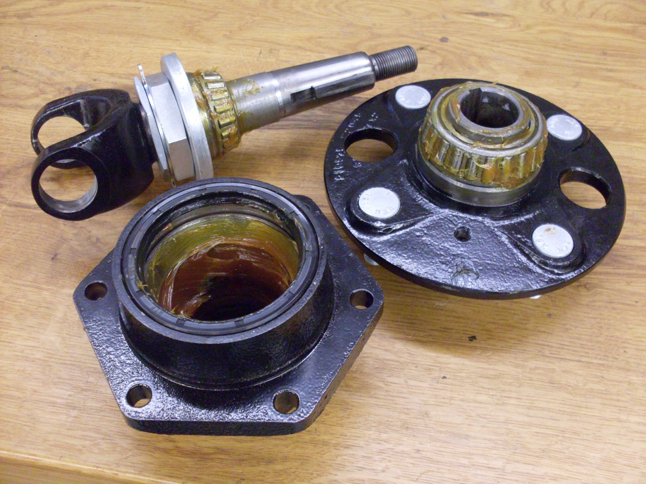
All the parts for the hub assembly.
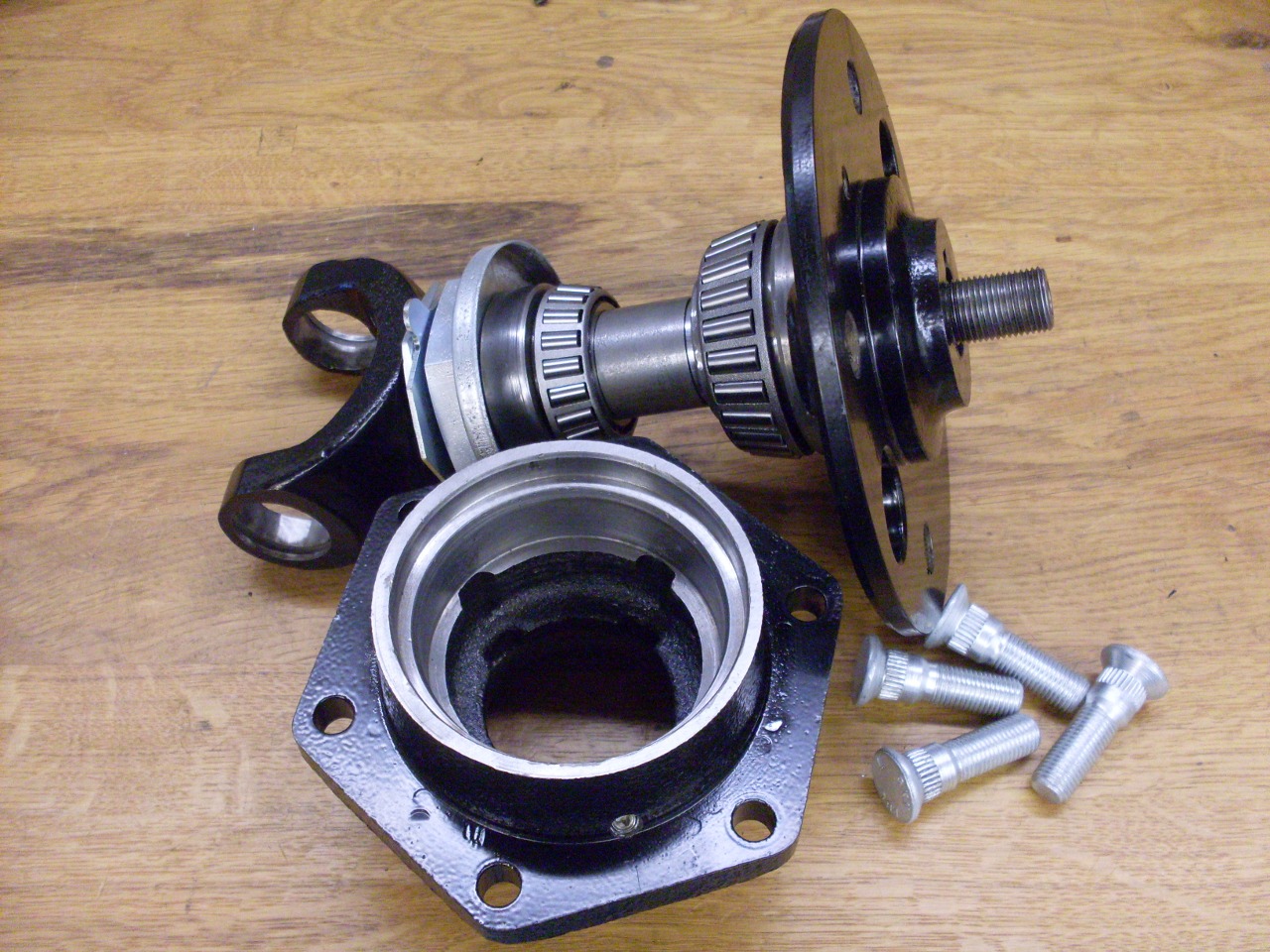
Press in the outer races and grease everything up.
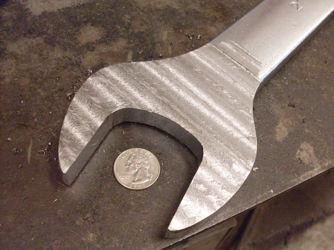
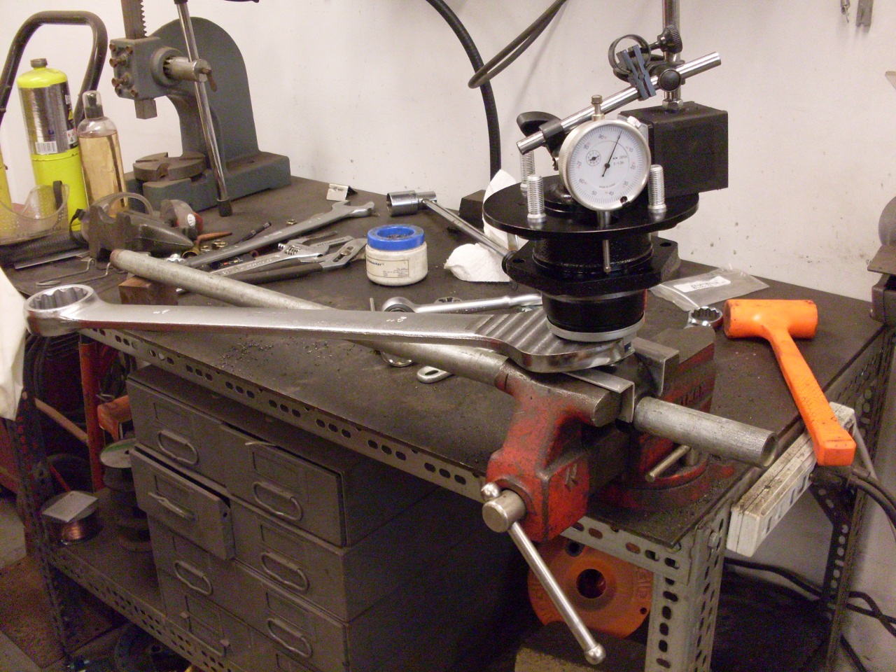
Setting
the bearing float is interesting. The wrench for the big
adjusting nut can only be 1/2" or so thick. I bought a 2" wrench
and took almost 1/4" off the thickness. I had to open up the jaws
a little, too. The wrench is over two feet long.
Turning
the nut a little at a time, and checking float. The nut starts
out just pushing the bearing up on the axle. It's obvious when it
begins to crush the spacer between the bearings. A 1" pipe
through the U joint yoke helps to steady the assembly when leaning on
the big wrench. I found it easy to sneak up on 0.002" float.
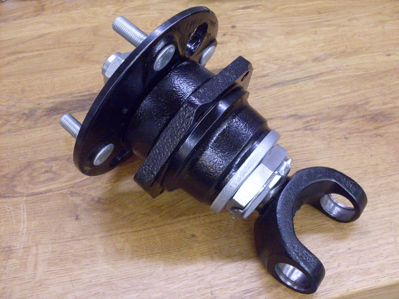
One rebuild hub assembly.
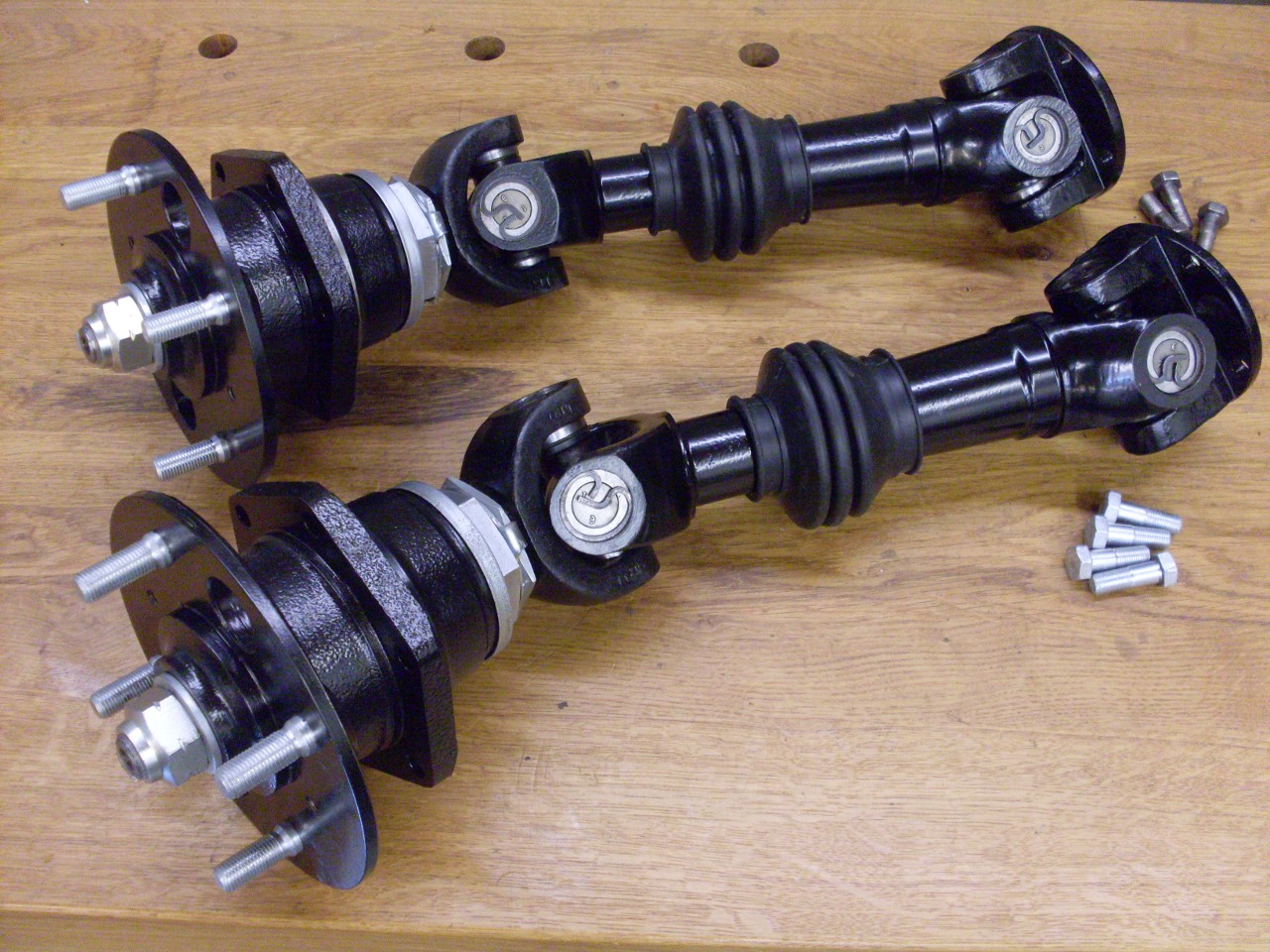
Installed the U joints, and we have axles ready to go.
comments to: elhollin1@yahoo.com
To my other TR6 pages