To my other TR6 pages
August 1, 2014
Rack & Pinion
[Click the pics for a bigger view.]
The
TR6 uses a simple rack and pinion assembly for steering. Each end
of the rack carries an inner ball joint for tie rods to the steering
arms.
My rack & pinion assembly looked about as bad as the
rest of the car on the outside. However, as a pleasant surprise,
I found the internals to still be very well lubricated, and in very
good condition.
Now
I normally don't dwell on my mistakes, let alone document them for the
world to see, but I'll describe here a bonehead moment that occured
when disassembling the rack housing. I had removed the pinion
gear, and wanted to remove the bottom bushing that it rides in. I
was somehow under the impression that the hole in the bottom of the
housing was blanked off by a welch plug that had to be driven out from
the inside. Even though a little thought would have shown that
this is silly, I proceeded to try to drift out the plug from the pinion
side. Even the fact that the "plug" refused to move despite
considerable force didn't phase me. Only after I finally broke
out the bottom of the alloy housing did it dawn on me that the bush and
the thrust bearing, which I thought was the plug, would have easily
pushed out from the bottom up.

I
was doubly frustrated because I thought I'd just ruined a rack and
pinion assembly that was in excellent shape. I finally resolved
that as penance for such a stupid mistake, I'd go to whatever heroic
lengths it would take to repair the damage I caused. After a
little thought, I came up with a plan that was simple, though it took a
while.
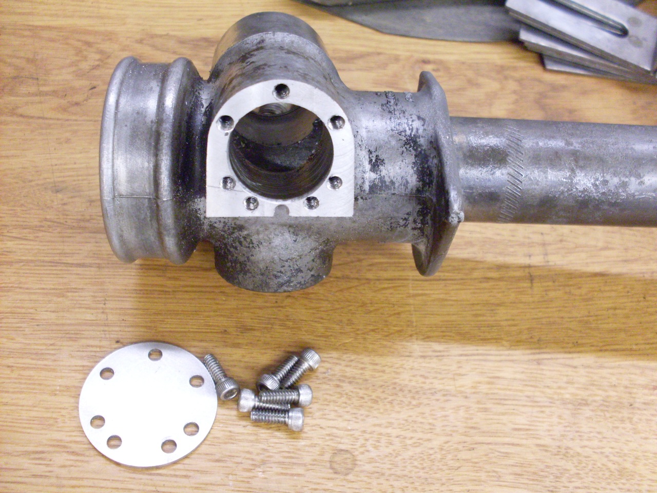
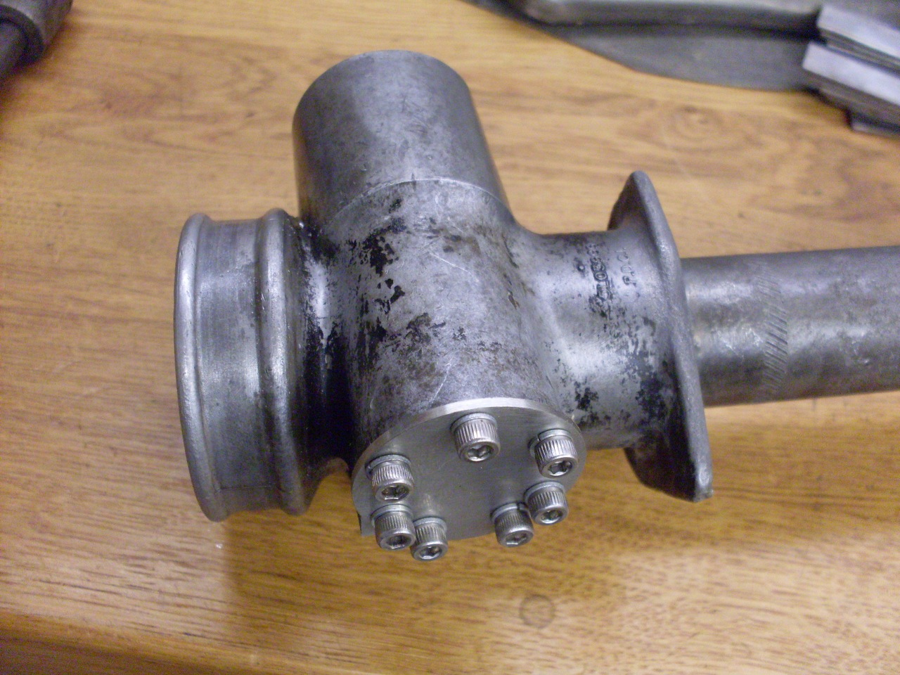
First, I milled off the bottom broken surface down
approximately to where the bottom of the internal bore had been.
Then drilled and tapped six 8-32 holes around the perimeter to
hold a stainless cap. The picture shows evidence of another
maddening lack of forethought. The lowest of the six holes didn't
have enough meat, and broke through the edge of the casting slightly.
It would still hod a screw, but not with much torque. If I
had only just rotated the hex pattern by 30 degrees, it wouldn't have
happened. To compensate, I placed two additional tapped holes,
one on either side of the bad hole. This explains the odd screw
pattern.
With
that barely controlled disaster behind me, I resumed the
reassembly of the rest of the pinion part of the unit. I checked
the fit of all the bushes and they were so good, I couldn't see how new
parts could provide any improvement. Likewisewith the rack bush.
The only new parts in the assembly was the O ring for the pinion
shaft, an a couple of additional shims (because of my "redesign").
After painting the rack & pinion housings and replating
damper cap and plug, I started to put it all back together. The
parts inside the pinion housing are put together as stock,
including the thrust bearing, so the pinion shouldn't know the
difference.


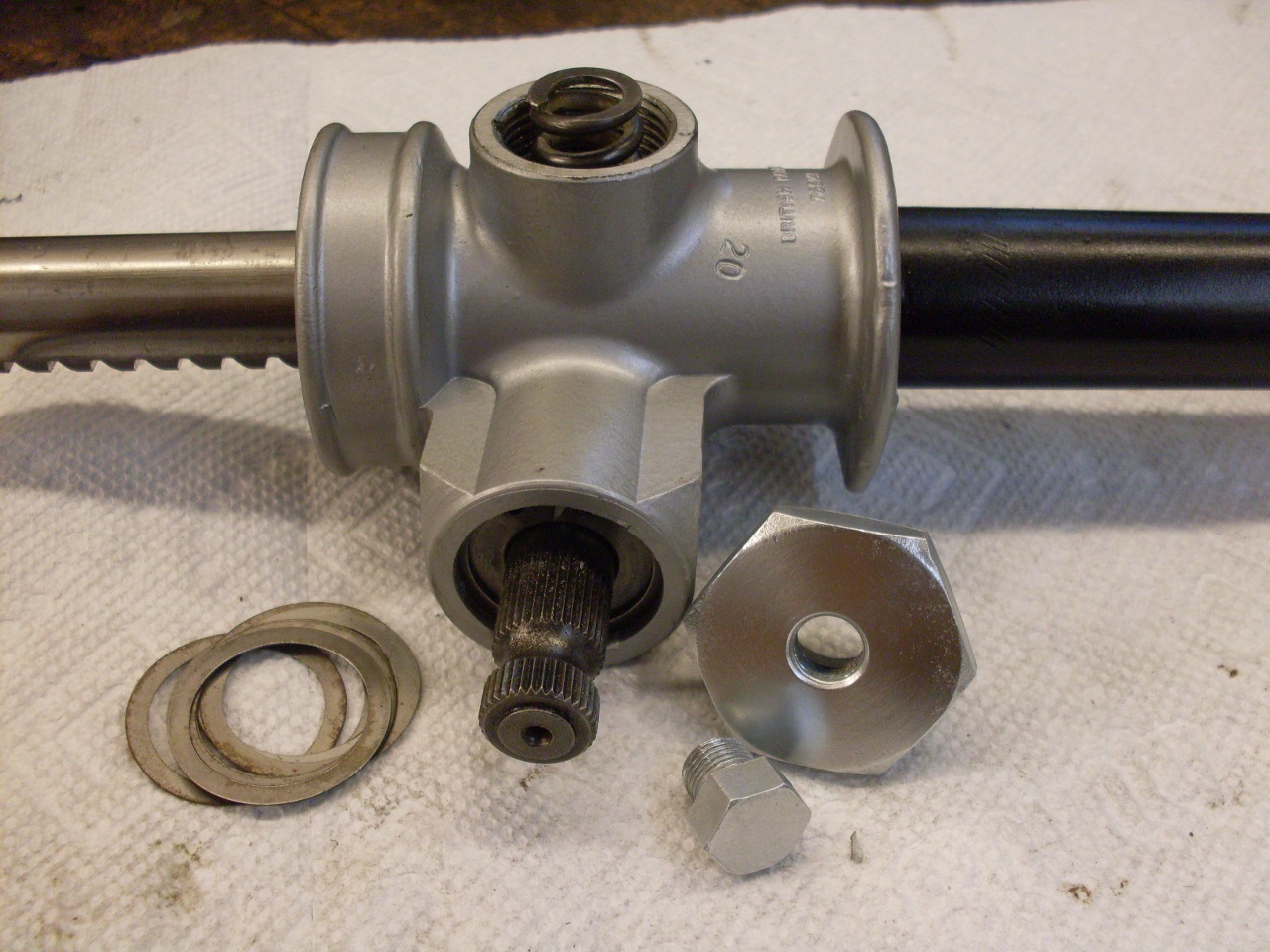
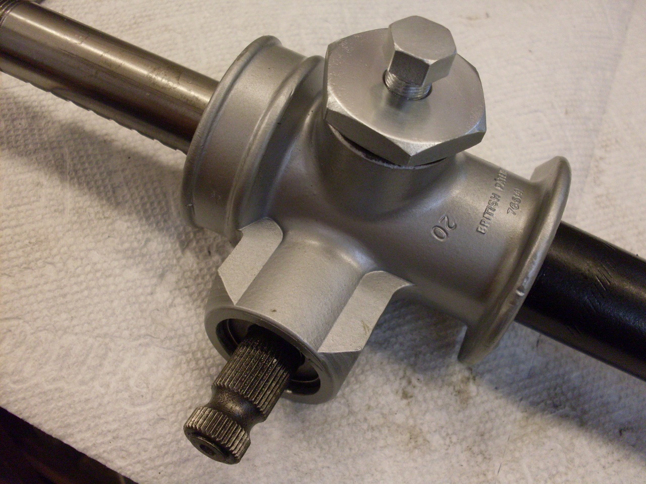
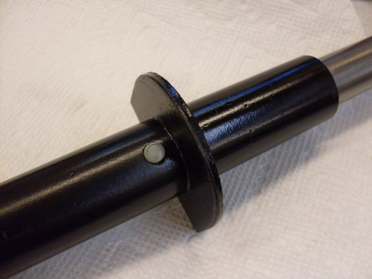
I even managed not to lose the little plastic plug. I'm not sure of the purpose for this. Pressure relief, maybe?
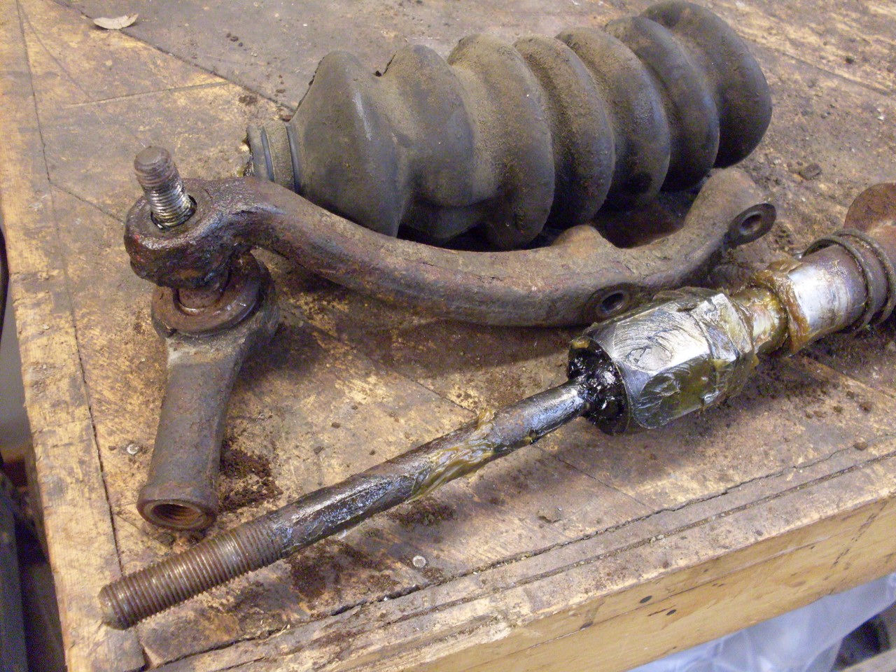
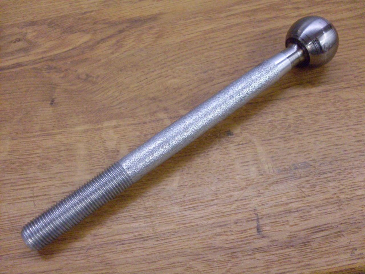
Next
up was the tie rods with their inner ball joints. Everything in
the joints was still covered with clean looking grease, and felt tight
and smooth. The balls were bright and shiny, with hardly any
evidence of wear. The rod part of the tie rods were pretty rusty.
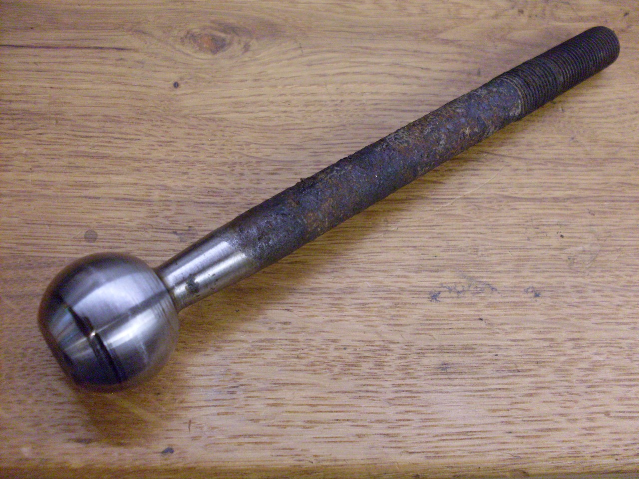
Most
of the ball joint parts live out their lives bathed in grease, so
plating is unnecessary. The exception is the rod part of the tie
rods. These are at least partially exposed to the elements where
the gaiters don't cover. I thought zinc plating the tie rods
would be worthwhile, but didn't want to interfere with the nice surface
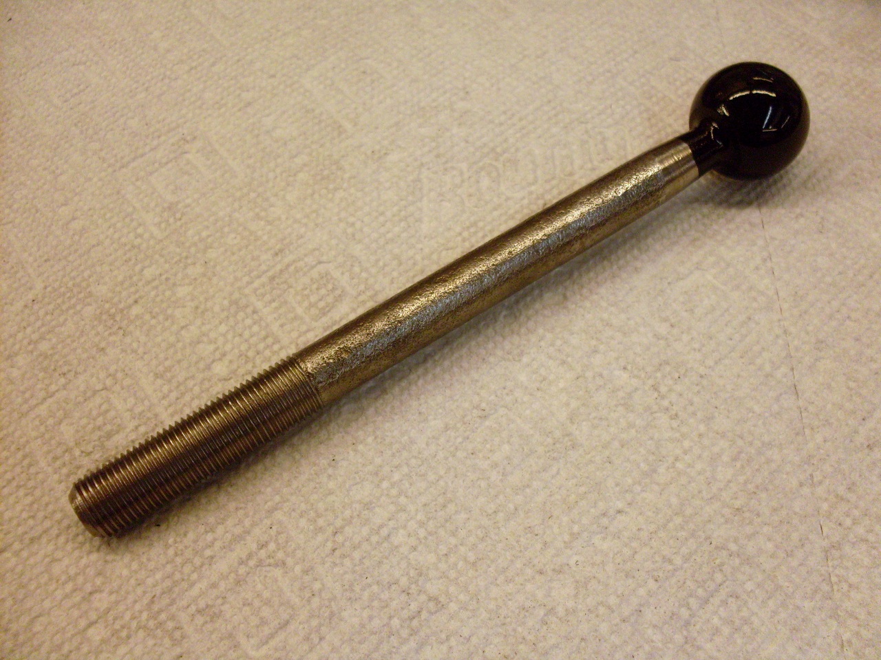
of the ball. I ended up selectively plating the tie rods by
spraying a couple of coats of lacquer paint on the ball parts to act as
a resist to the plating. Lacquer dries fast and is easy to
remove. It worked out well.
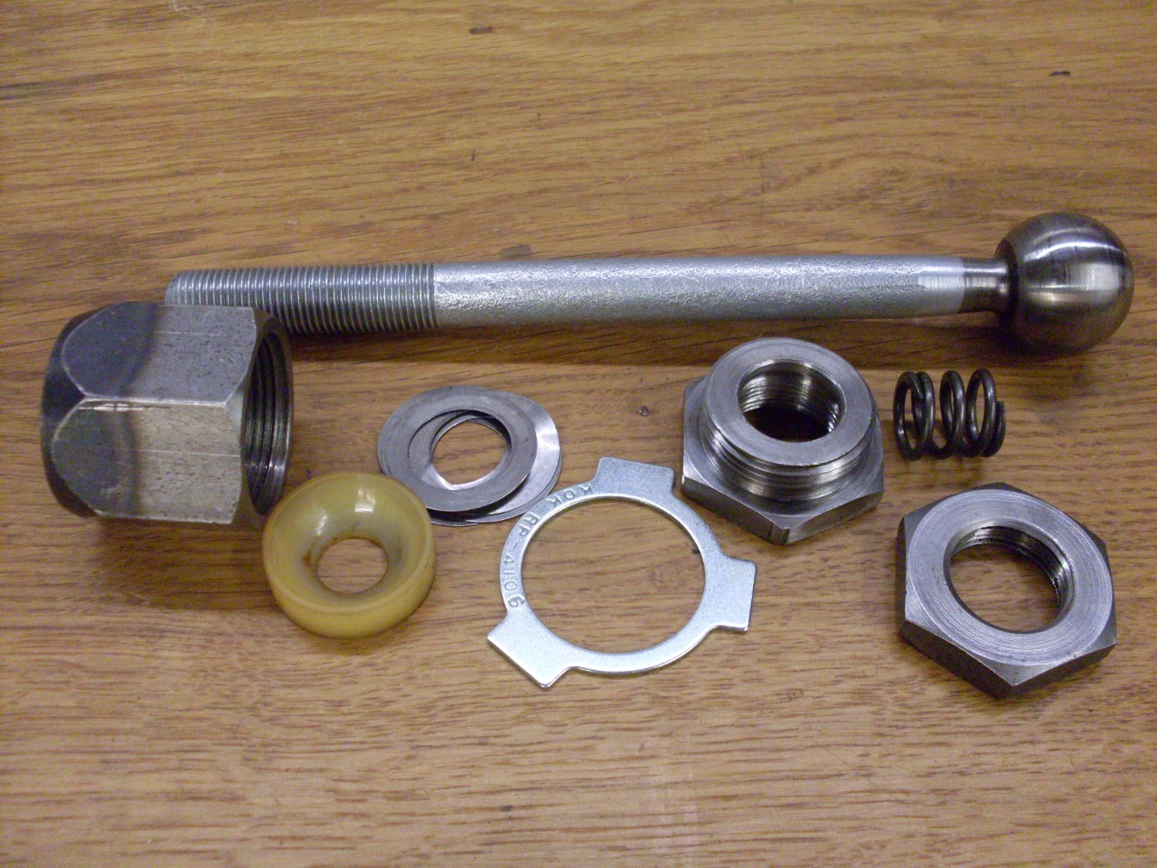
After
close inspection, I decided that as for the pinion parts, there was
nothing to gain by buying anything new. The reassembled the ball
joints with the original parts (except foir the tab washer) and shims,
and fresh grease, showed firm but smooth movement.

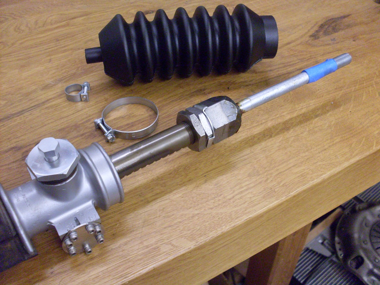
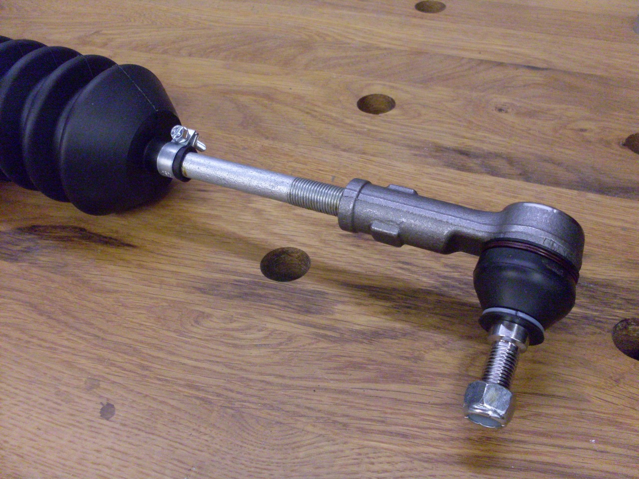
Tie
rods attached to the rack. There is a spec for the distance
between the face of the ball joint lock nut and teh center of the tie
rod end. This is dificult to measure with the gaiter in place, so
that's what the tape is for--it marks how far the tie rod end should be
screwed on.

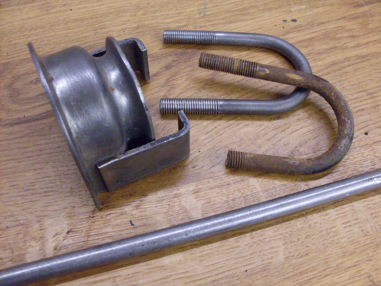
Last
parts to deal with were the mounting clamps for the rack and pinion
assembly. One of the U bolts had broken during teardown, and I
had some trouble trying to source an exact replacement. Some
places wanted me to buy the entire clamp, which was silly. I
figured a simple U bolt shouldn't be hard to make, and it wasn't, but
it did take a little time. The original bolts have 5/16-24
threads, but they must have been rolled on, since the actual rod is
only about 0.280". My bolt made from 5/16 rod is a little fatter,
but finally fit OK.
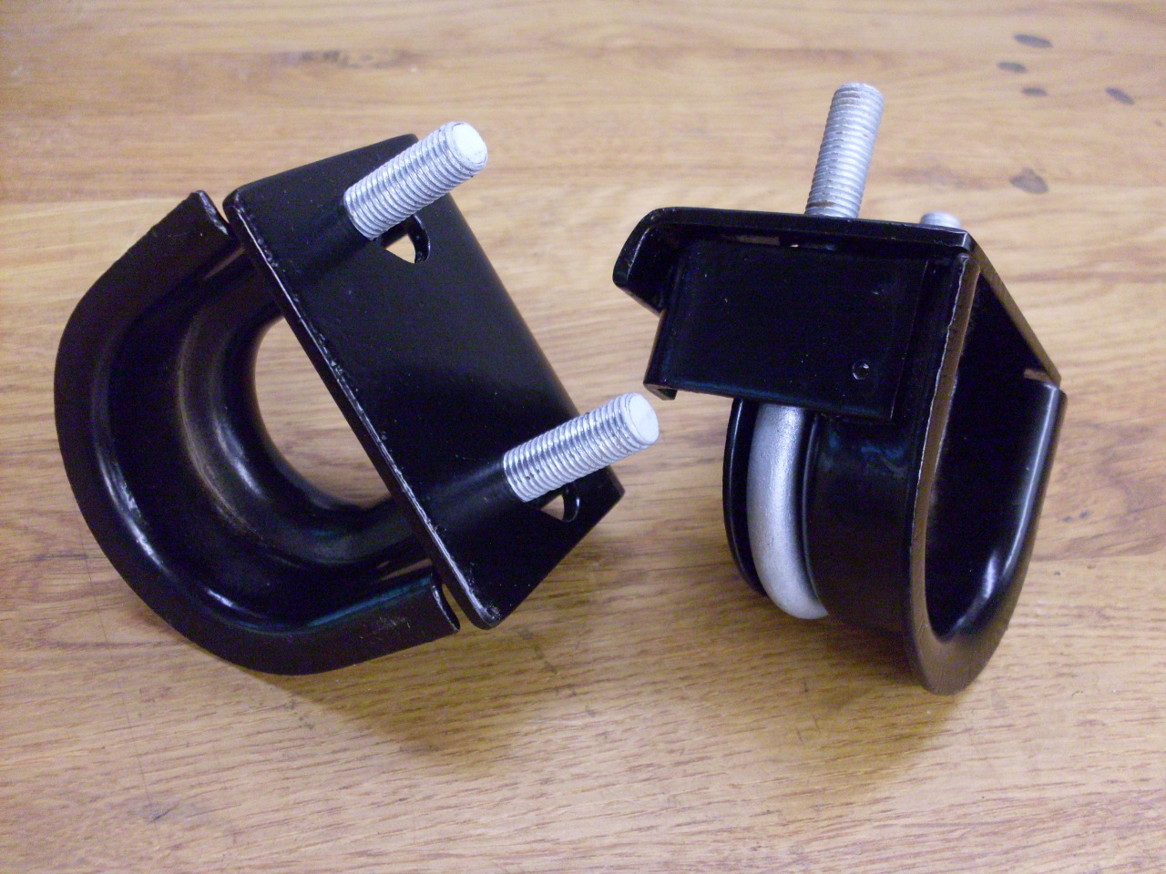
After
plating and powder coating, the old clamps are ready for service again.
Last pic includes one of the new poly rack mounts.
New tie rod end. Oops, forgot the lock nut.
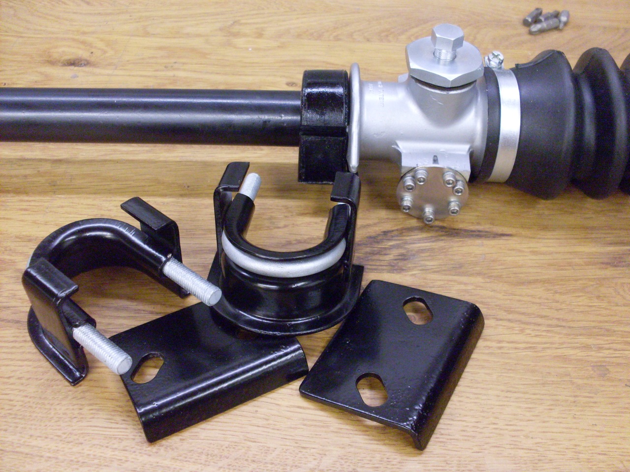
The
resilient mounts need to be preloaded before tightening the U bolt
clamps. There is a factory tool for this, but this is my version.

Everything bolted in. Time to move to the rear suspension.

Comments to: elhollin1@yahoo.com
To my other TR6 pages