To my other TR6 pages
July 30, 2014
Front Spindles & Hubs
[Click the pics for a larger view]
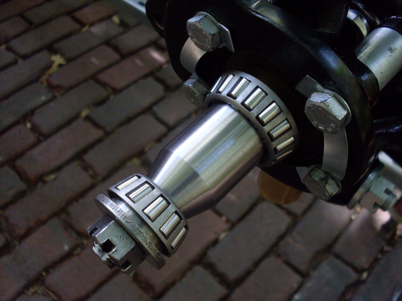
The
TR6 has a short front stub axle, or spindle, located in a taper in the
vertical link. Each spindle carries carries a pair of opposed
tapered roller bearings that support the road wheel hub, to which the
disc brake rotor is bolted.
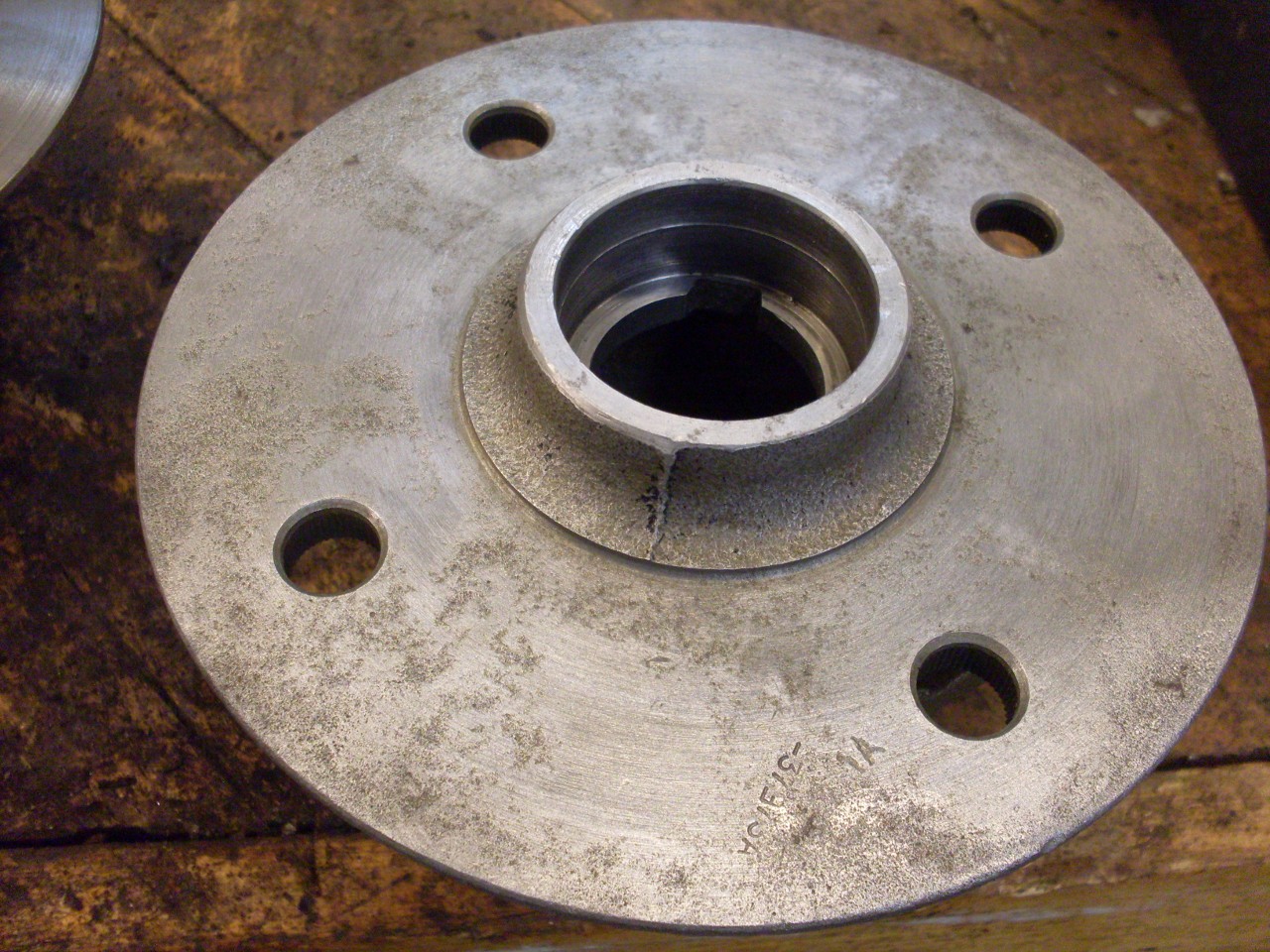
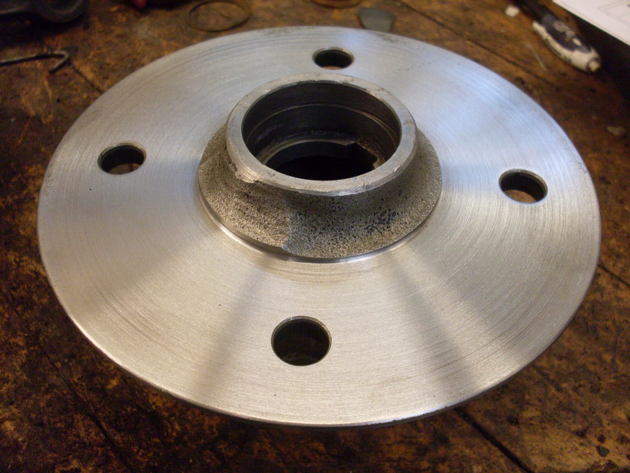
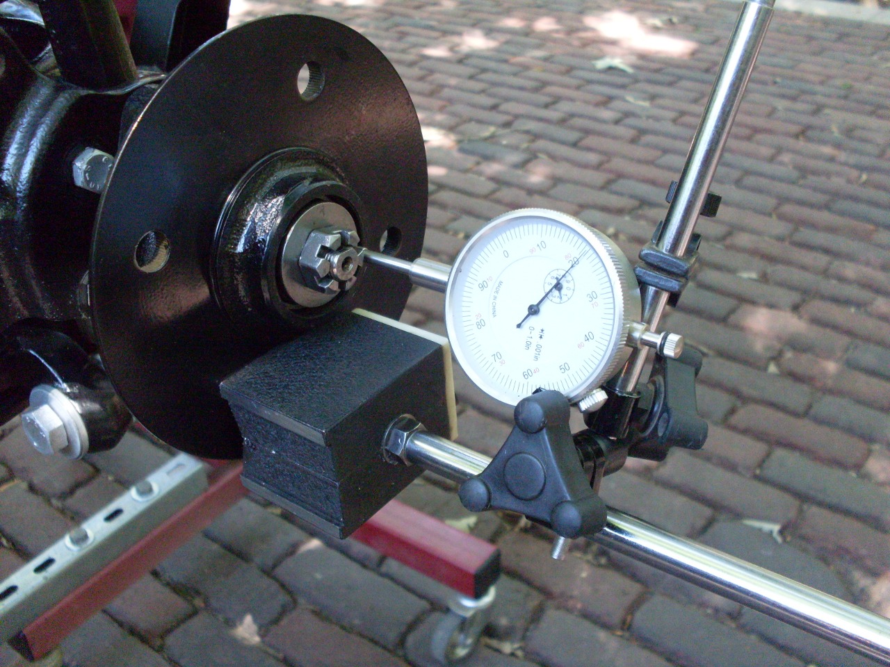
My
hubs were pretty dirty and rusty, but cleaned up OK. After rust
removal there were the telltale pits left behind. While the pits
are not serious, I determined that one of the hubs had about 0.020" of
runout on the wheel mounting flange. I figured there was enough
meat onthe flange to rectify both the runout and the pitting.
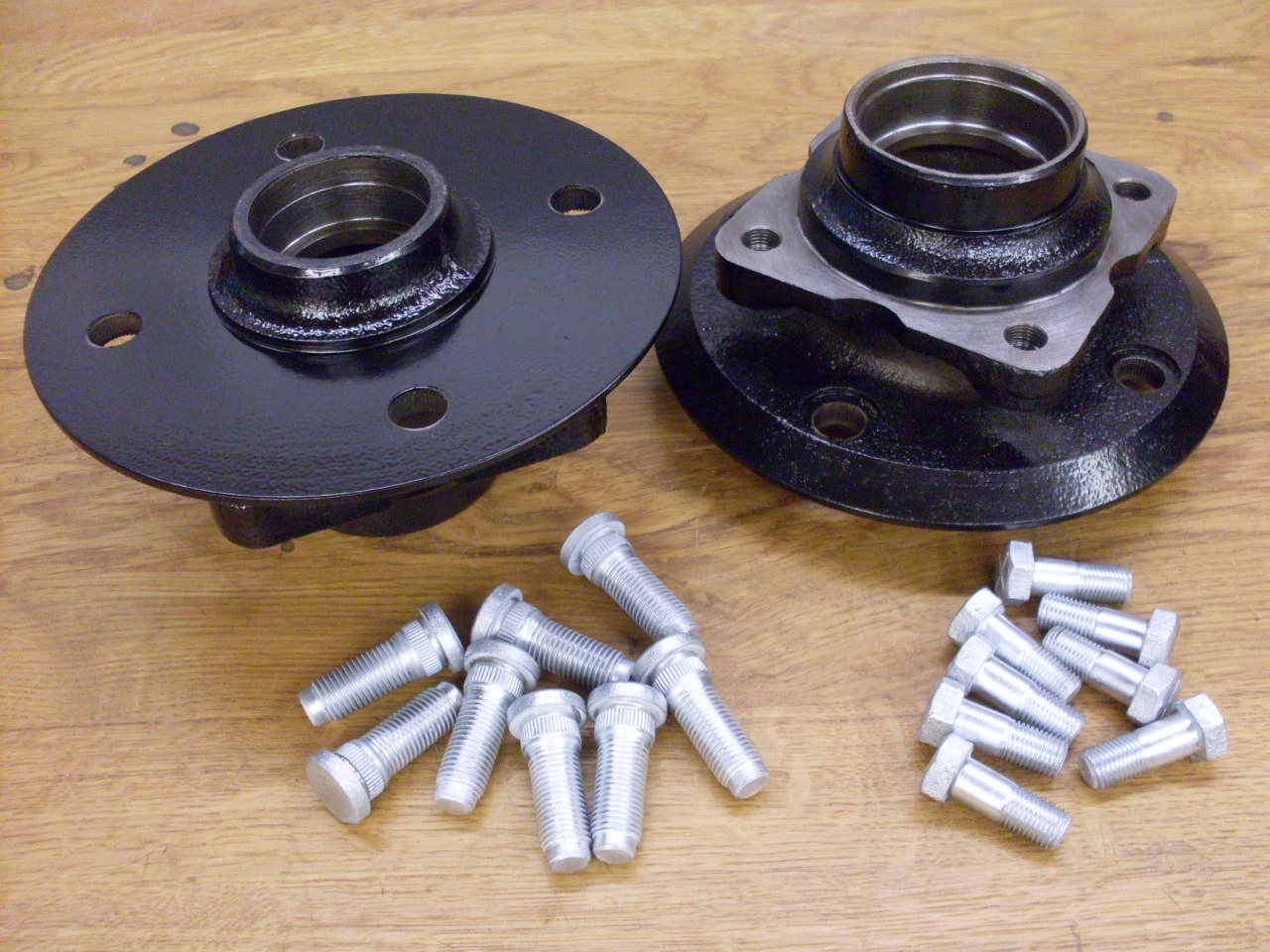
Then a quick powder coat and replate on the hardware.
The spindles themselves were in really good shape.
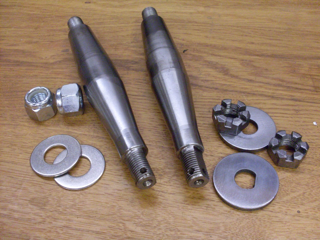
The
TR6 wheel bearing design was a little disappointing to me. While
the sizing of the spindles and bearings themselves seem OK, it's the
provision for setting end float that bothers me. In this design,
the spindle nut directly moves the outer bearing inward, and clearance
is accomplished basically by leaving the spindle nut a little slack.
Since the castle spindle nut can be pinned at half-flat intervals
(1/12 turn), and the spindle thread is 1/2-20, the calculated available
end float settings are a little more than 0.004 apart. It's
mathematically conceivable that it could be impossible to achieve the
0.003-0.005" end float spec.
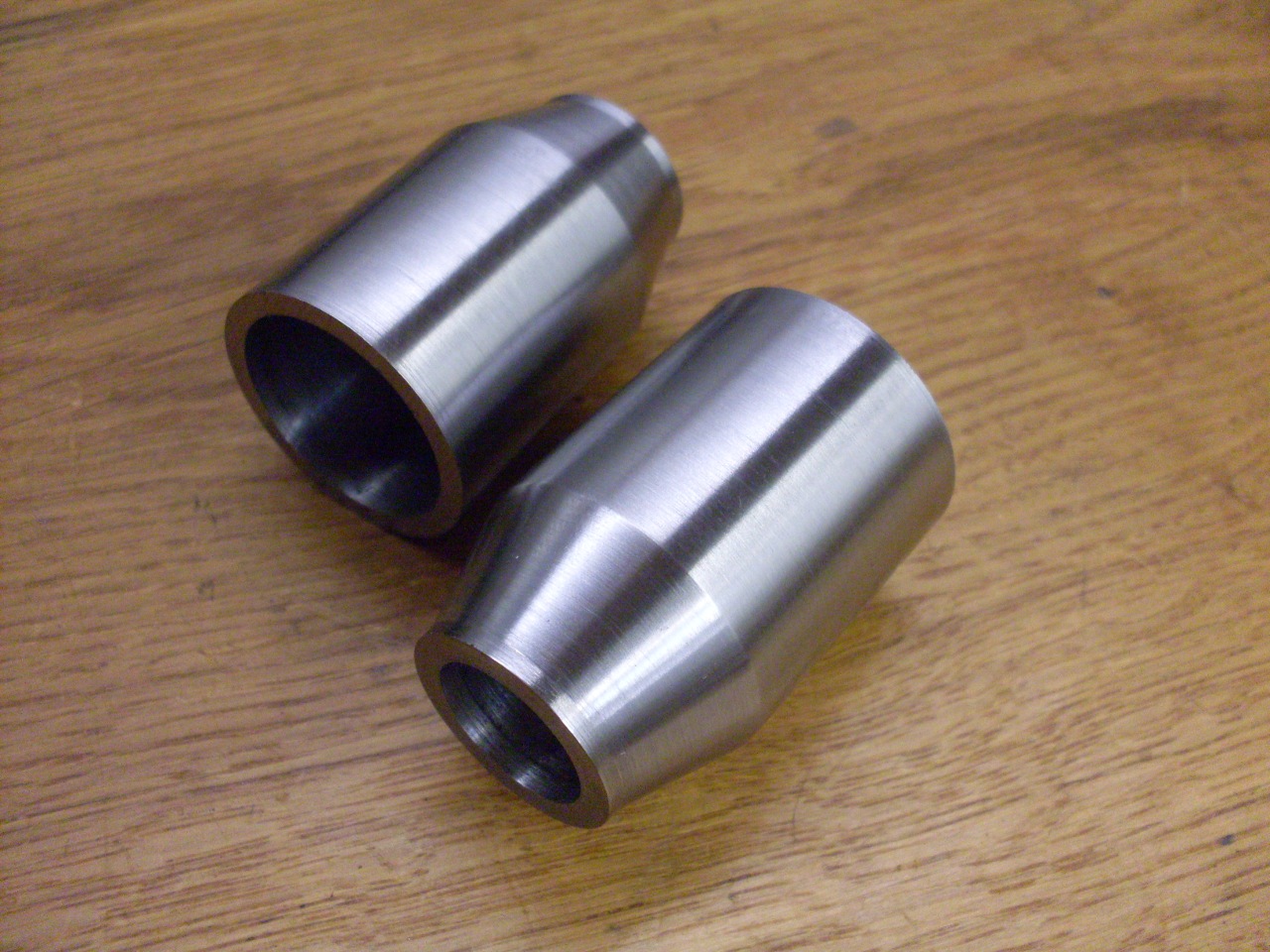
This
certainly isn't an unusual setup, but a better design in my opinion,
and one used by other small Brithish cars of the era, includes a
spacer or distance piece between the inner races of the two bearings.
This provides a rigid "stack" from the vertical link to the
spindle nut. The nut can be torqued properly, and the float is
set by the length of the spacer--or, more practically, by the thickness
of shims stacked with the spacer. In addition to being a more
positive and flexible way to set end float, the stack, which is in
compression, works with the spindle, which is now in tension, to
provide a stiffer truss-like assembly.
All
this is pretty well known in the TR6 community, as evidenced by the
availability of kits that provide spacers and shims to convert to the
"better" design. The kits seem a little pricey to me, though, and
I was pretty sure that I could come up with something just as good.
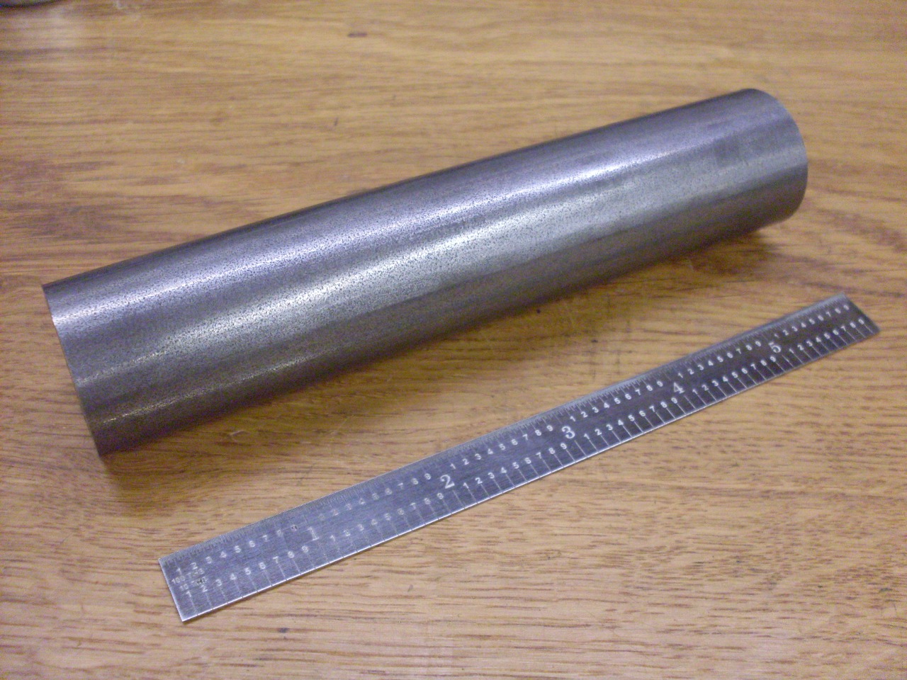
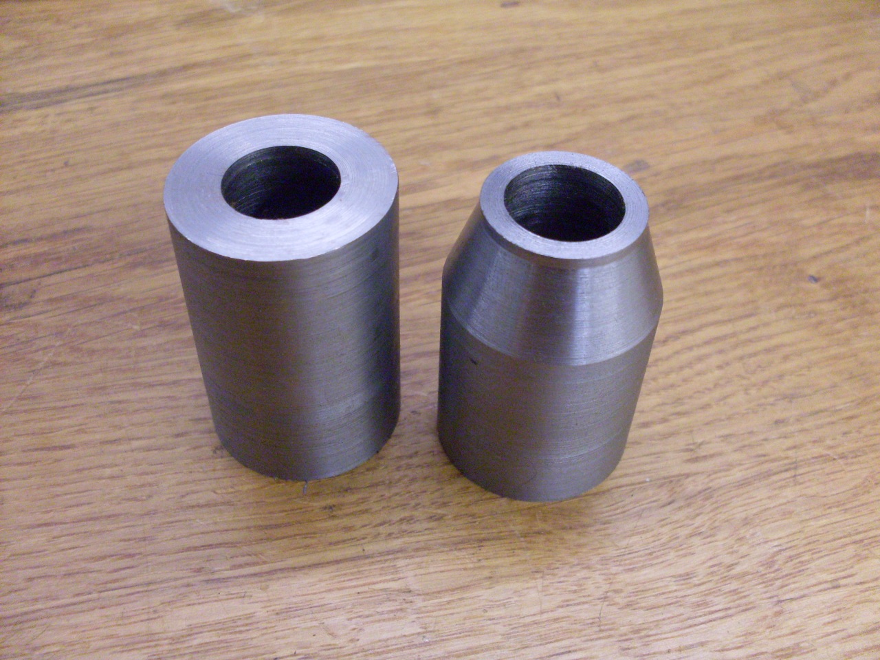
I
started with a $10 hunk of chrome moly 4140 steel. It's a pretty
simple machining job, with no really critical dimensions. The
length just has to be slightly less than the final distance between the
two bearings, since the shims will be added as needed to achieve final
spacing.
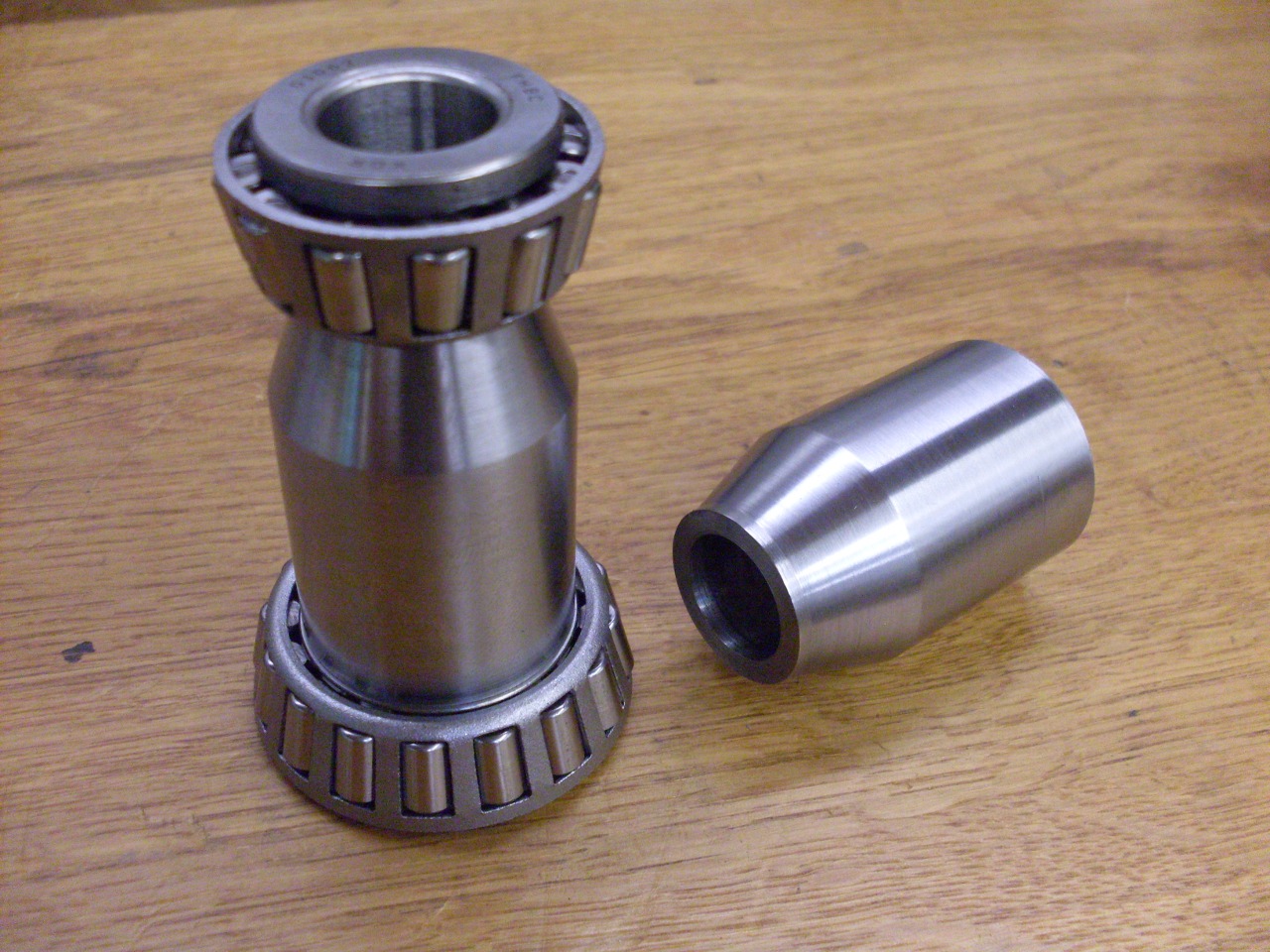
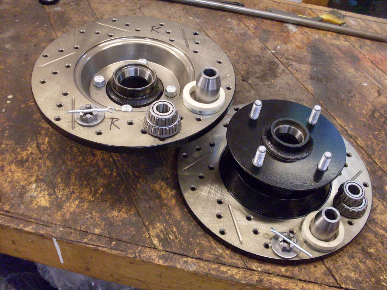
The right shims are found by trial and error.
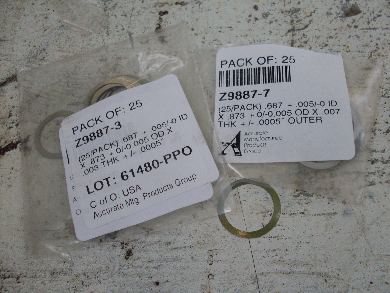
Once the right combination of shims is found, the rest of the hub assembly can be built up, including the brake rotors.
Once
I derusted my rotors, I found them to be still within spec for
thickness, but barely. There probably wasn't enough meat to even
clean up the rust pitting. There was also at least one sizeable
gouge on the surface. I don't know what caused that.
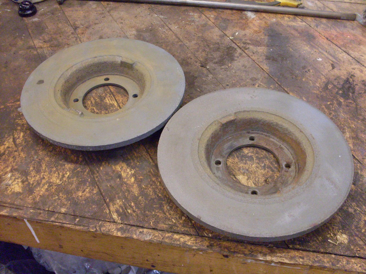
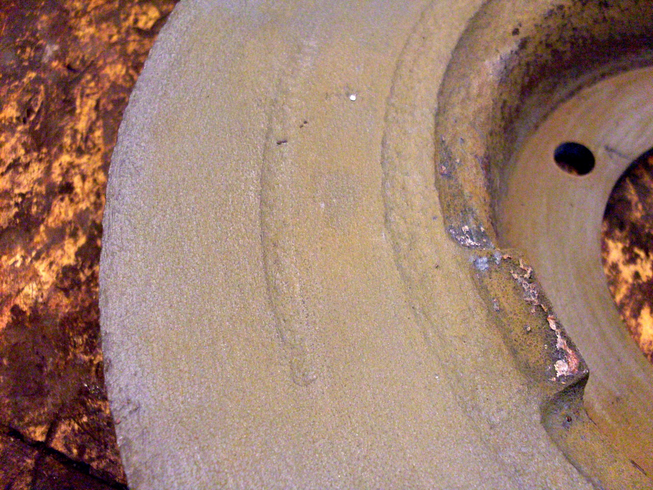
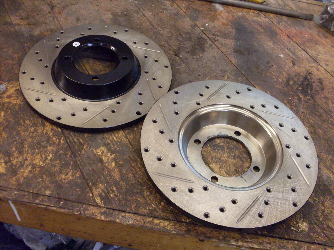
This, of course, meant new rotors. I opted for a slight upgrade to drilled and slotted units.
Before the hub assemblies can go on, the brake shield has to be slid into place.
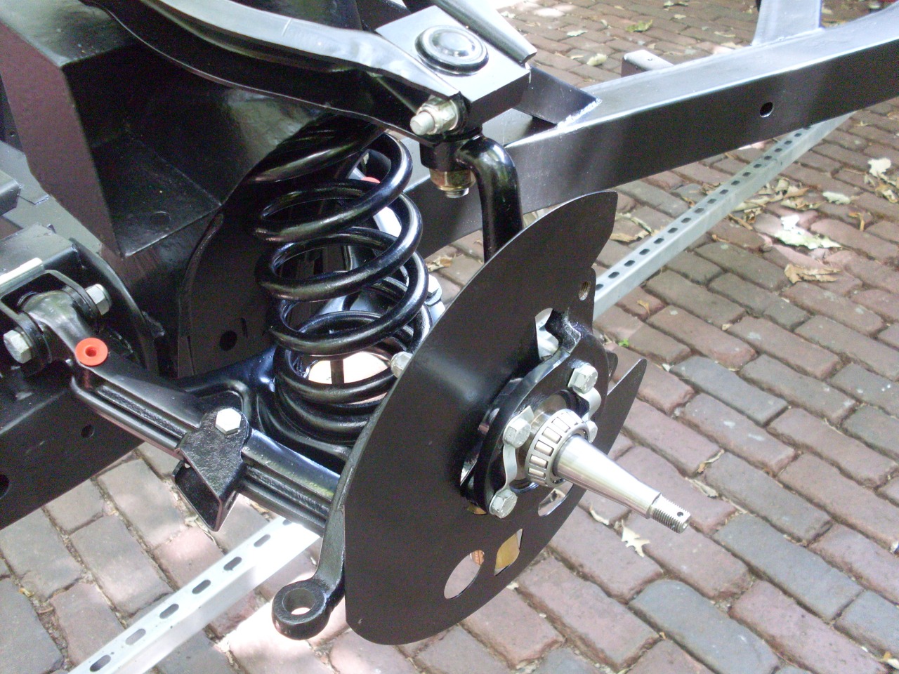
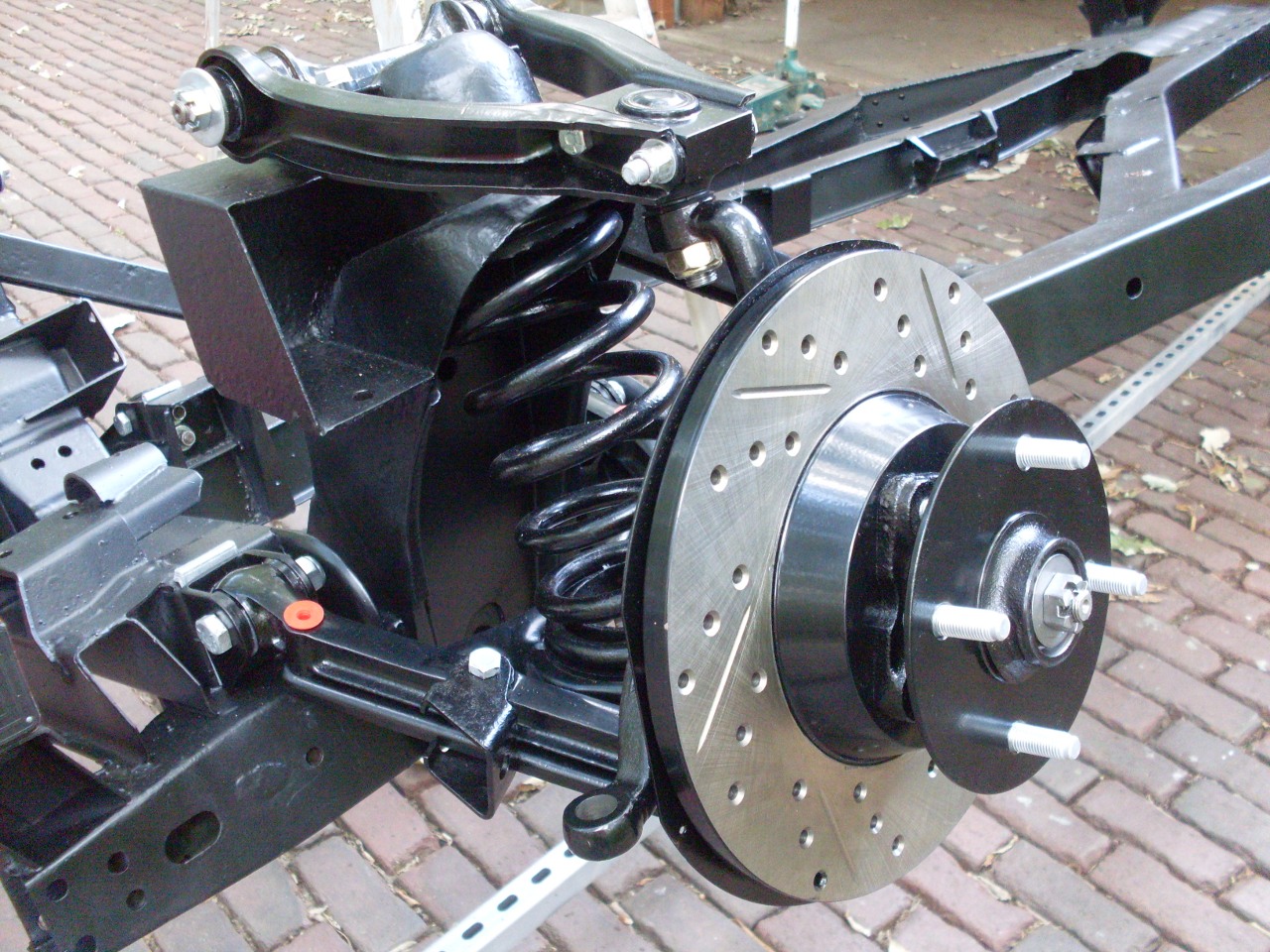
Front end is getting close to a wrap.

Comments to: elhollin1@yahoo.com
To my other TR6 pages