To my other TR6 pages
April 13, 2014
Flywheel and Clutch
With the engine and transmission finished, the only remaining pieces between them are the flywheel and clutch.
The flywheel is a massive piece of iron that rotates on the rear
end of the crankshaft. It serves to damp the torque pulses from
the individual cylinders, smoothing out the delivery of energy to
the drive train. However, one of the downsides of a heavy flywheel is
that it takes significant energy to increase its rotational velocity.
This can take away from the linear acceleration the car is
capable of.
One popular performance modification for these and
many other engines is to lighten the flywheel by an amount that will
allow better acceleration, but not impair the smoothing action.
Unfortunately, while simple in principle, it's a little more
complicated than just hacking pieces of the flywheel off. First,
the flywheel must maintain sufficient strength to withstand the very
large forces generated at high RPMs. Second, the flywheel has to
remain balanced so that it doesn't contribute vibrations of its own.
Beyond these things, it turns out that it is very important where the weight is removed. A flywheel resists acceleration by its moment of inertia
(MI). The total MI of a flywheel depends not only on the mass of
the wheel, but how the mass is distributed. Mass near the
periphery of the wheel contributes much more to the total MI than mass
nearer the spin axis. So to be most effective, flywheel material
has to be removed as far from the spin axis as possible, consistent
with strength and balance.
One
interesting way to look at the
effect of lightening a flywheel is to calculate the equivalent weight
that would have to be removed from the car to give the same increase in
acceleration. The basis for this comparison goes something like
this: When accelerating, some of the energy developed by the
engine must be used to accelerate the flywheel. This energy is
not available to drive the wheels. If we lighten the flywheel so
that it takes less energy to accelerate it, the more the drive train
will see. There's more, and here is where it gets interesting.
Since there is a gear reduction between the engine and the drive
wheels, there is a torque multiplication. This means that any
increase in torque into the drive train will be multiplied by the gear
ratio before it gets to the wheels. This increased torque at the
wheels translates into a larger linear force on the pavement, which
means a higher acceleration for the car. One other way to get
higher acceleration for a car for a given linear force on the pavement
is to lighten the car. Given these two ways to get a car to
accelerate faster, we can compute the weight reduction of the car that
would give the same acceleration increase as a certain flywheel weight
reduction. Depending on where the weight is removed from the
flywheel, the exact drive train gear ratios, and the size of the drive
wheel, the multiplier can
easily be more than 10--that is, a pound of well placed metal removed
from the flywheel will give the same acceleration increase as
lightening the car by 10 pounds or more. Those afflicted with a
knack for math can see more detail on this here.
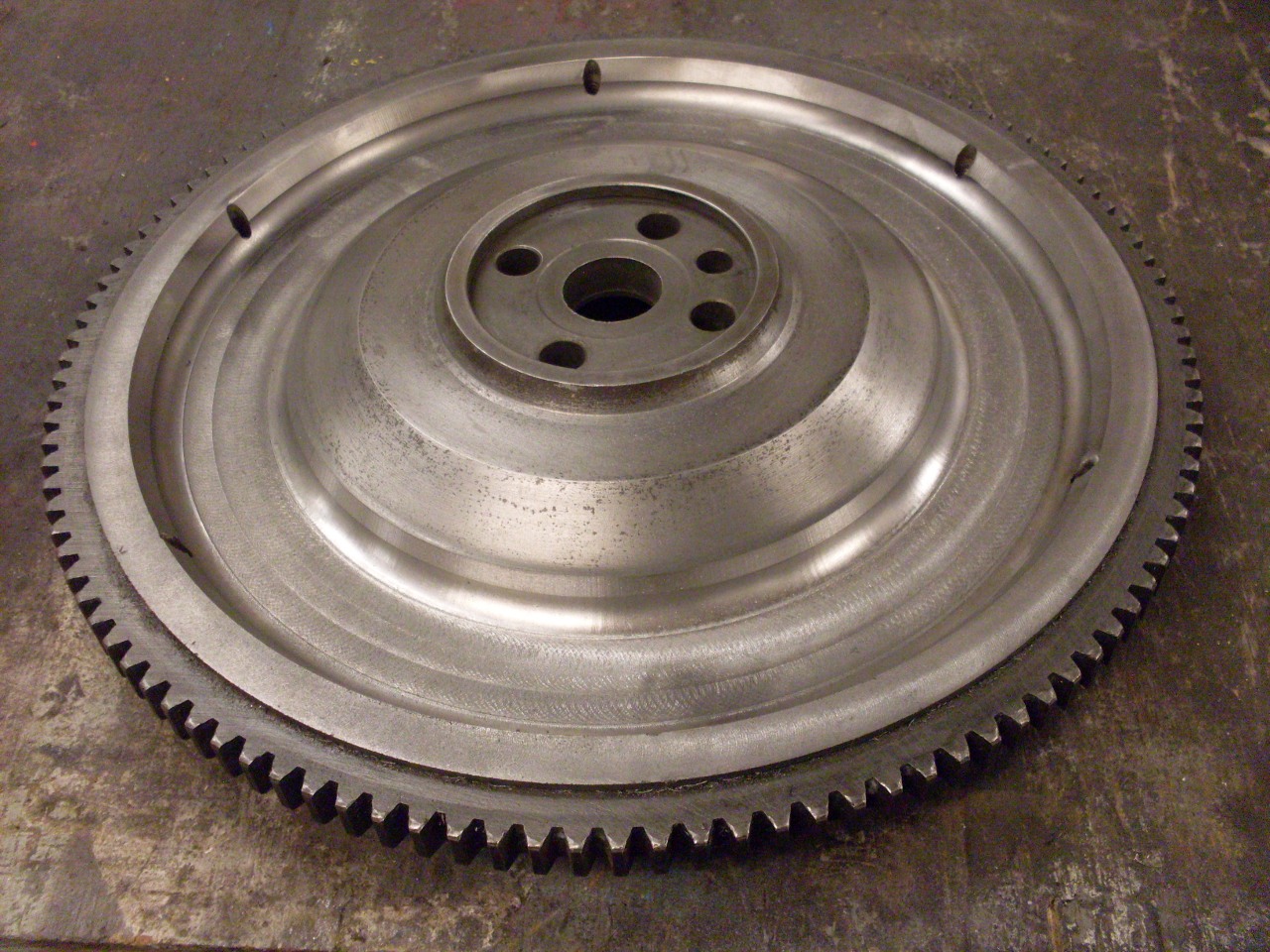
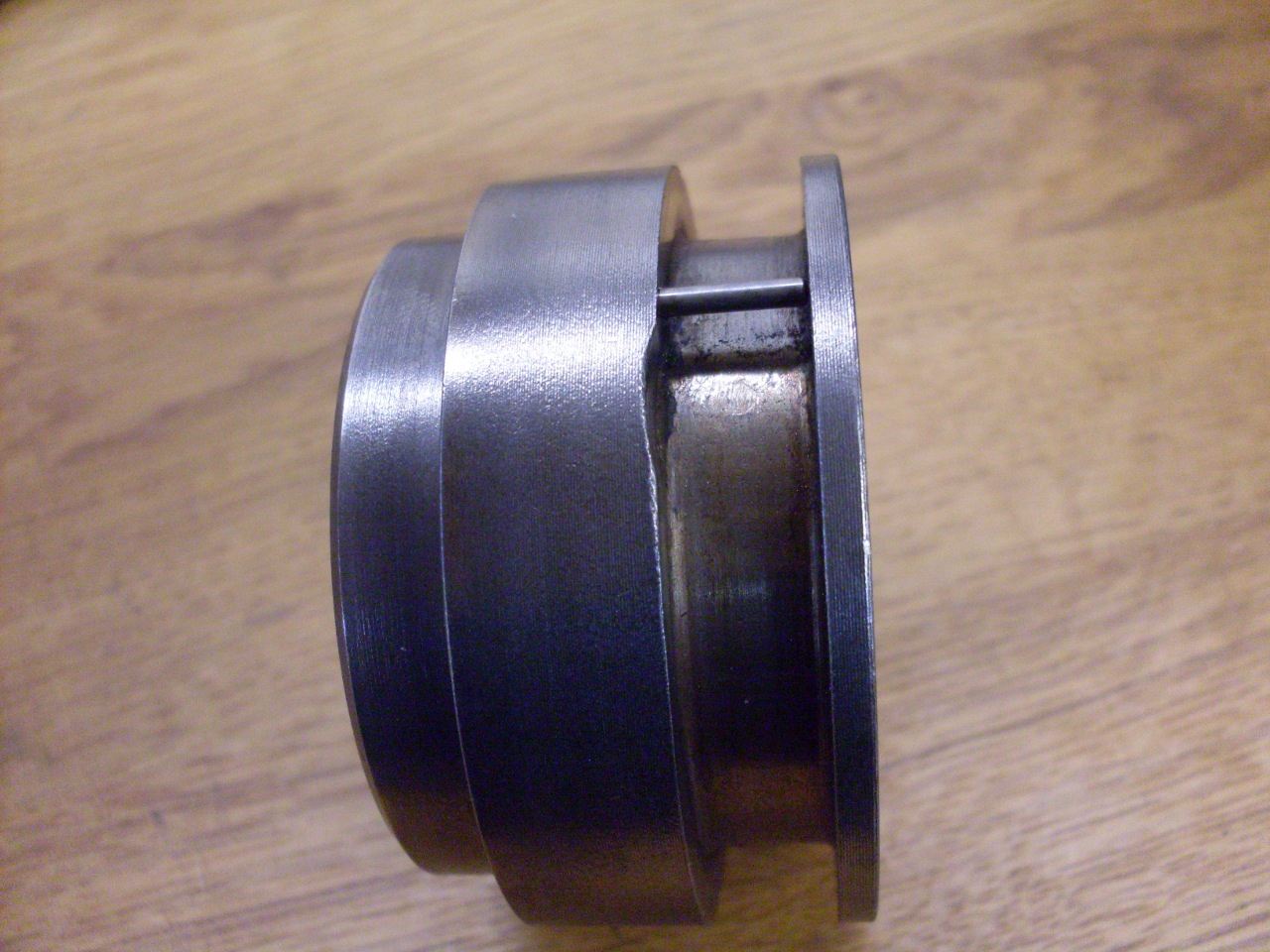
My flywheel as removed was dirty and rusty.

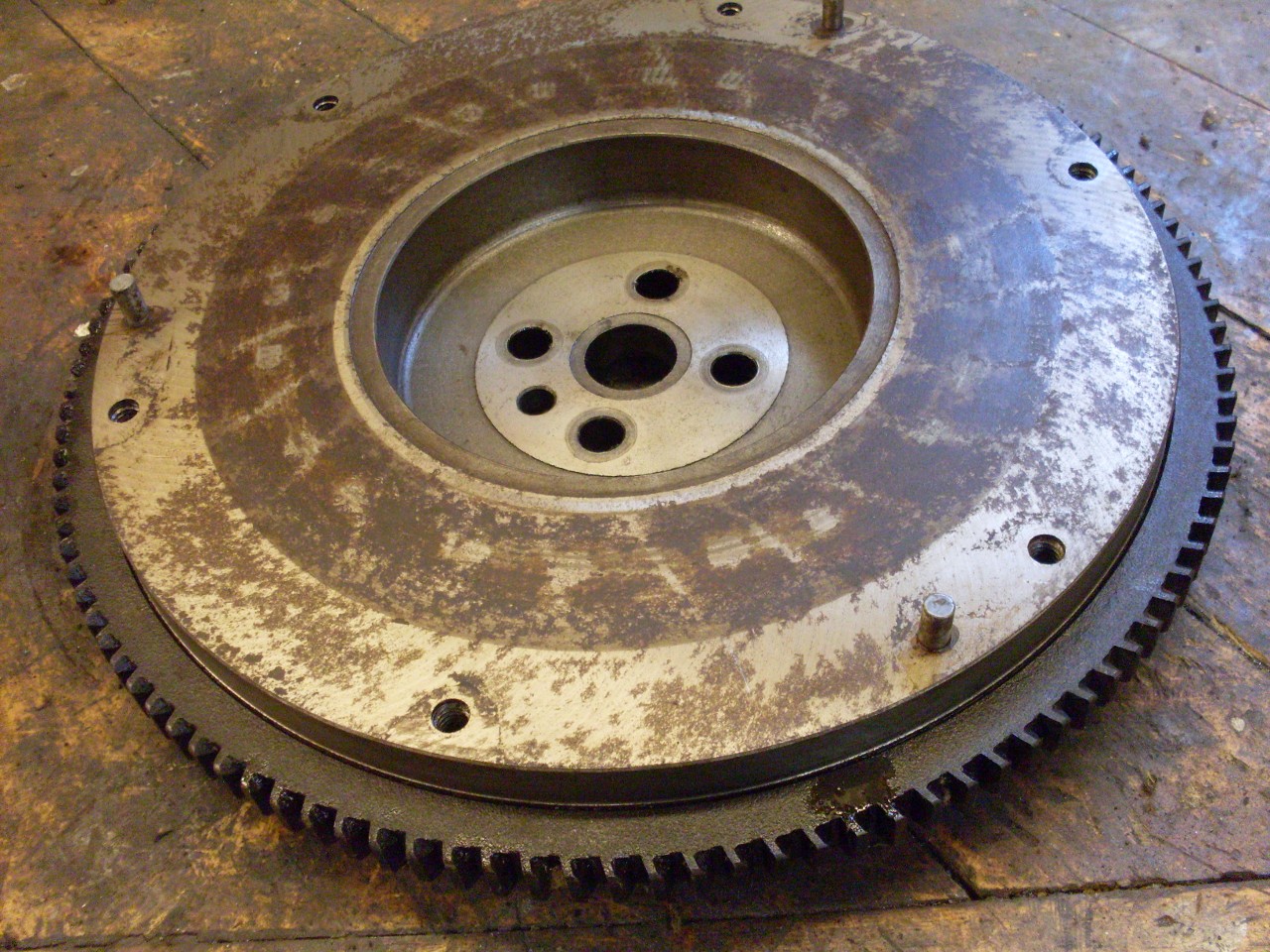
First
task was to clean it up to see if there were any obvious problems.
After this, I thought the flywheel was in pretty decent shape.
The friction surface still showed some evidence of the last grind
marks.

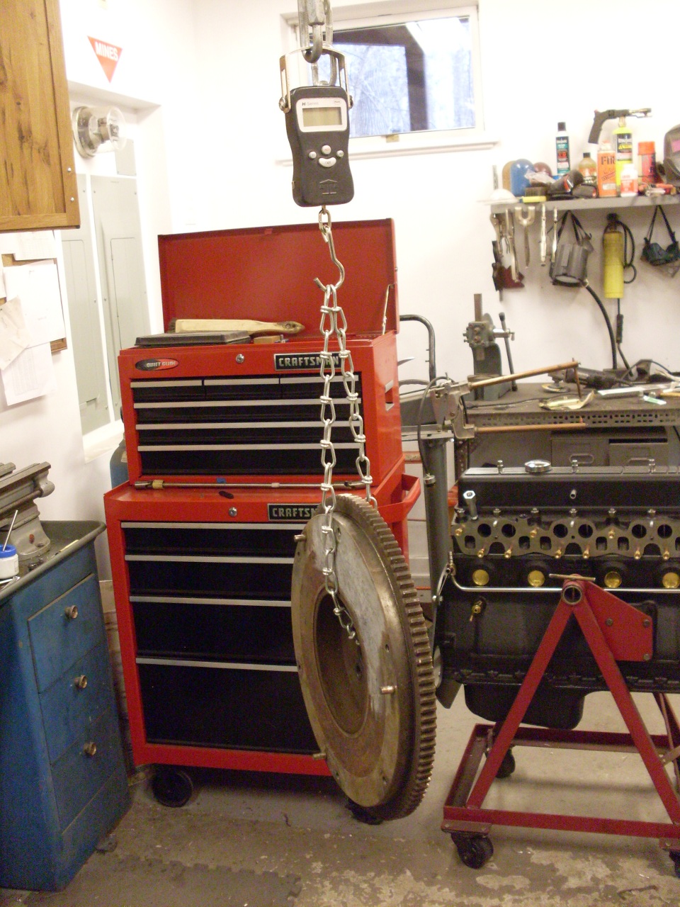
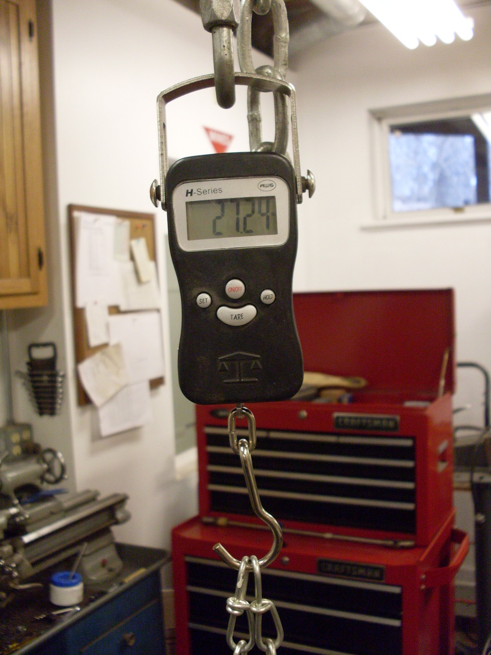
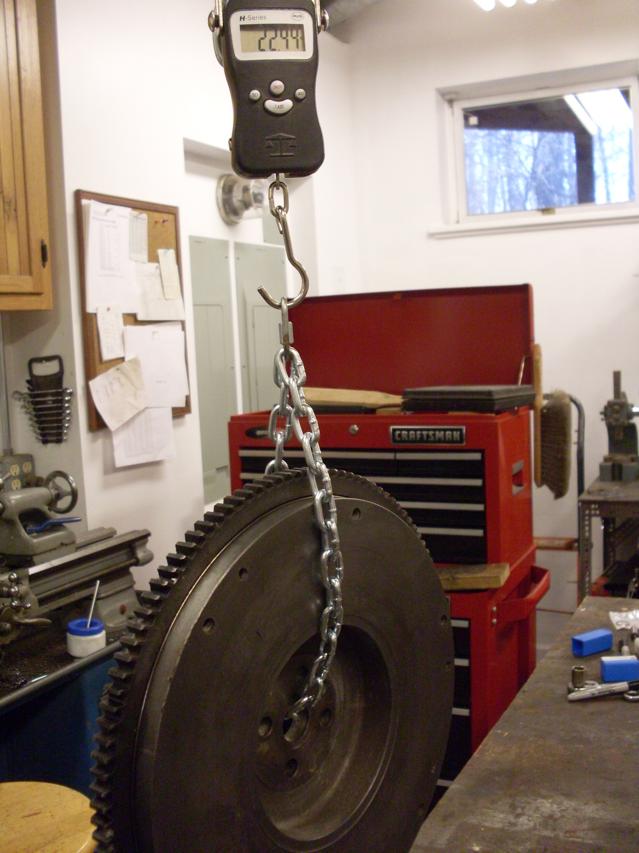
Then
I weighed the wheel so I'd know the starting point. It came in at
27.24 pounds. Many consider this to be a little heavy for these
cars anyway.
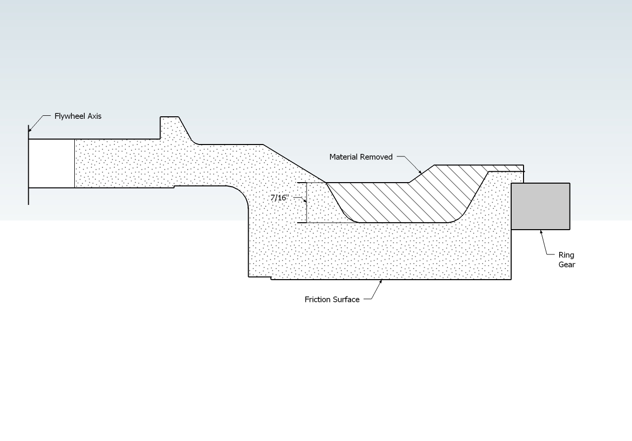
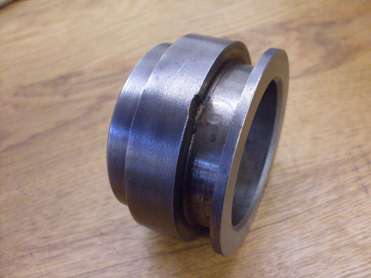
After
some careful measuring, I came up with a plan for material removal.
I calculated that this should remove around five pounds, but
being mostly towards the periphery, the effect should be maximized.
**DISCLAIMER**Please note that this plan for material removal is not
a recommendation. It is a description of what I did. Please don't
adopt what I have done here without a full understanding of the
principles involved, or professional advice.
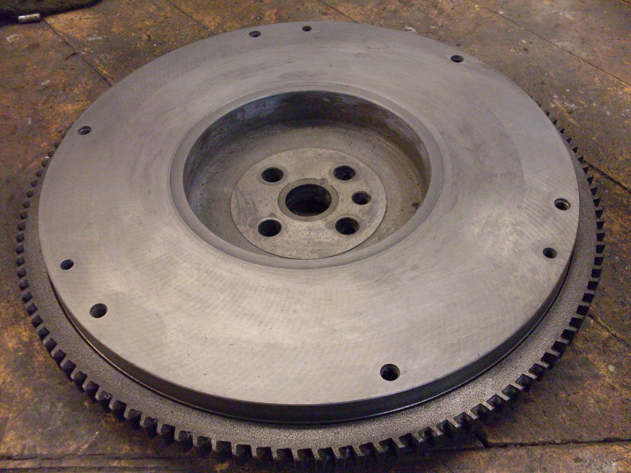
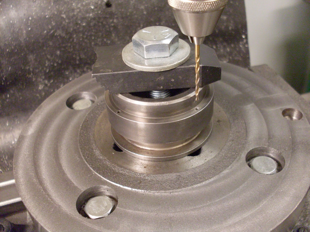
This
would normally be done on a lathe, but the flywheel is just a little
too big for mine, so the material was removed on a mill, as evidenced
by the tooling marks.
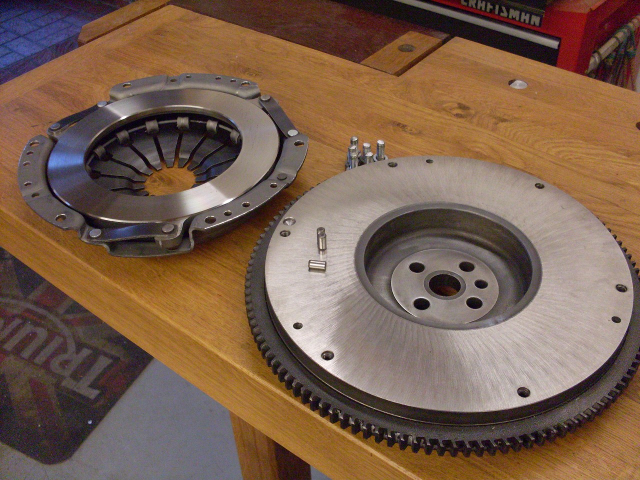
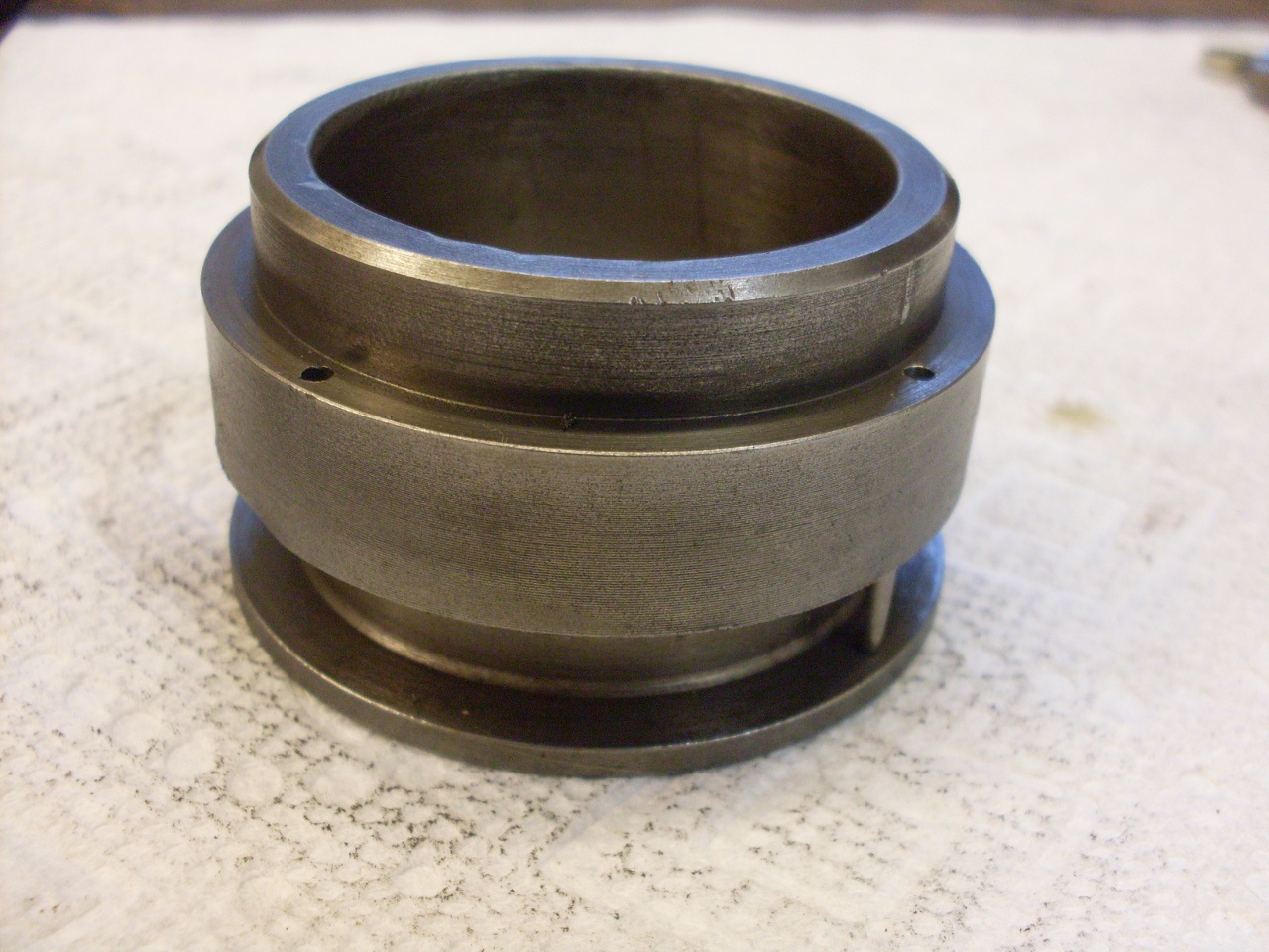
The
final weigh-in showed a new weight of 22.44 pounds--a loss of 4.8
pounds, pretty close to my estimate. I know my vacuum got a lot
heavier.
Then
it was off to a shop to have the flywheel surfaced and balanced.
Unexpectedly, I found that most shops, at least in my
area, did't have the small arbors necessary to balance TR6
flywheels. Finally found one, but it was 30 miles away.
One
other mod for a flywheel that is sometimes considered is
stepping. Stepping a flywheel consists of machining away a little
material on the part of the flywheel where the clutch mounts.
This in effect moves the pressure plate a little closer to the
flywheel. The motivation for doing this is often stated as
increased pressure on the clutch disc. This sounds intuitive, but
in reality, the result may be just the opposite. The problem is
that the belleville type springs used in diaphragm clutches have a very
non-linear rate curve. In fact, it is so non-linear that it often
has a region where the rate is actually negative. In this region,
increased displacement actually results in less
force. You can sometimes actually feel this in pushing the clutch
pedal--the required effort peaks early in the travel, then gets
smaller. It is in this negative rate region that a new clutch
operates. As the clutch disc wears thinner, there is less
displacement of the pressure plate, and the operating point moves up
the curve to higher pressure until it finally passes "over the hump" to
a region of positive rate where further wear reduces the pressure,
eventually to the point of slipping.
It
could be that the idea of stepping a flywheel is something left over
from the days of coil spring clutches with their simple linear rate
springs. Also, it is true that some stock flywheels are stepped,
but in these cases, the step was presumably a design parameter used to
get the desired operating point for the clutch. On the other
hand, stepping a flywheel as a modification has to be undertaken with a
good understanding of the spring rate curve for the particular clutch. I
didn't have any good reason for wanting to change the disc pressure,
let alone reducing it, so I didn't consider stepping any further.
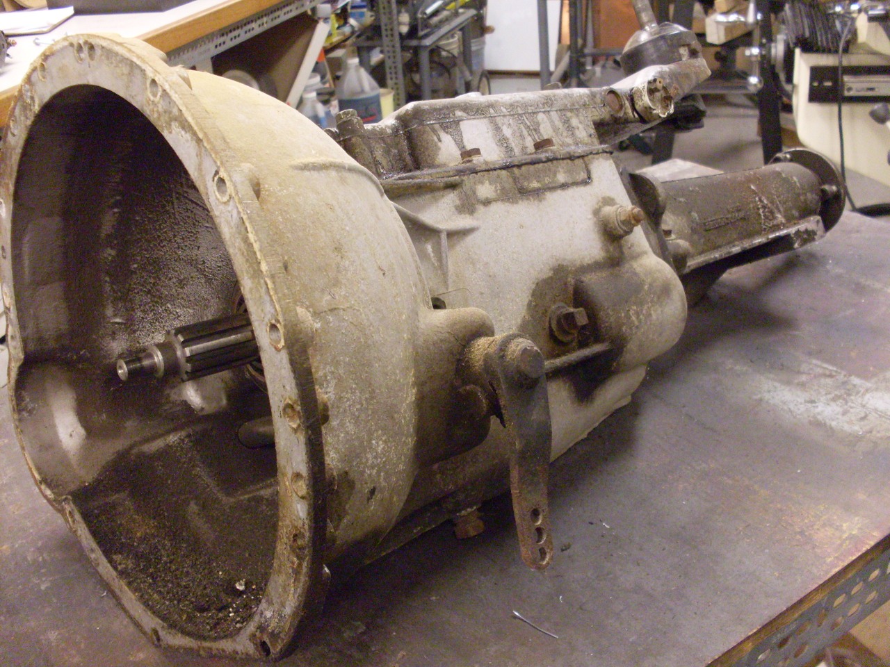
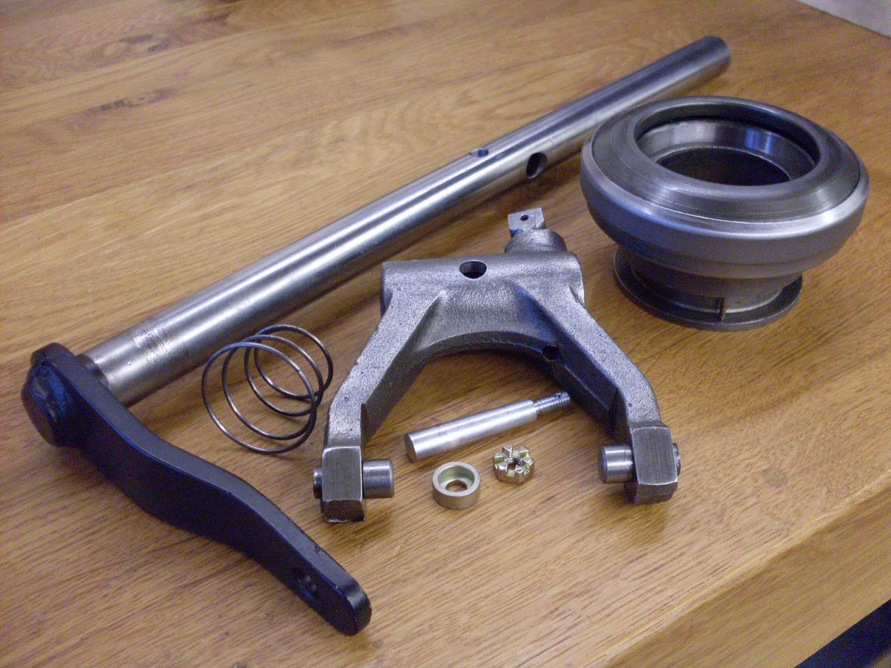
Clutch Linkage
The
TR6 uses a standard diaphragm clutch. The release (throwout)
bearing rides on a carrier that is moved by a fork. The fork is
fixed to a cross shaft that runs horizontally through the bell housing
and carries an arm on its drivers side end. The arm is actuated
by a hydraulic slave cylinder. There are a number of joints in
the overall mechanism, and each can contribute a little slop.
Most of the parts in this chain of
linkages needed some kind of attention.
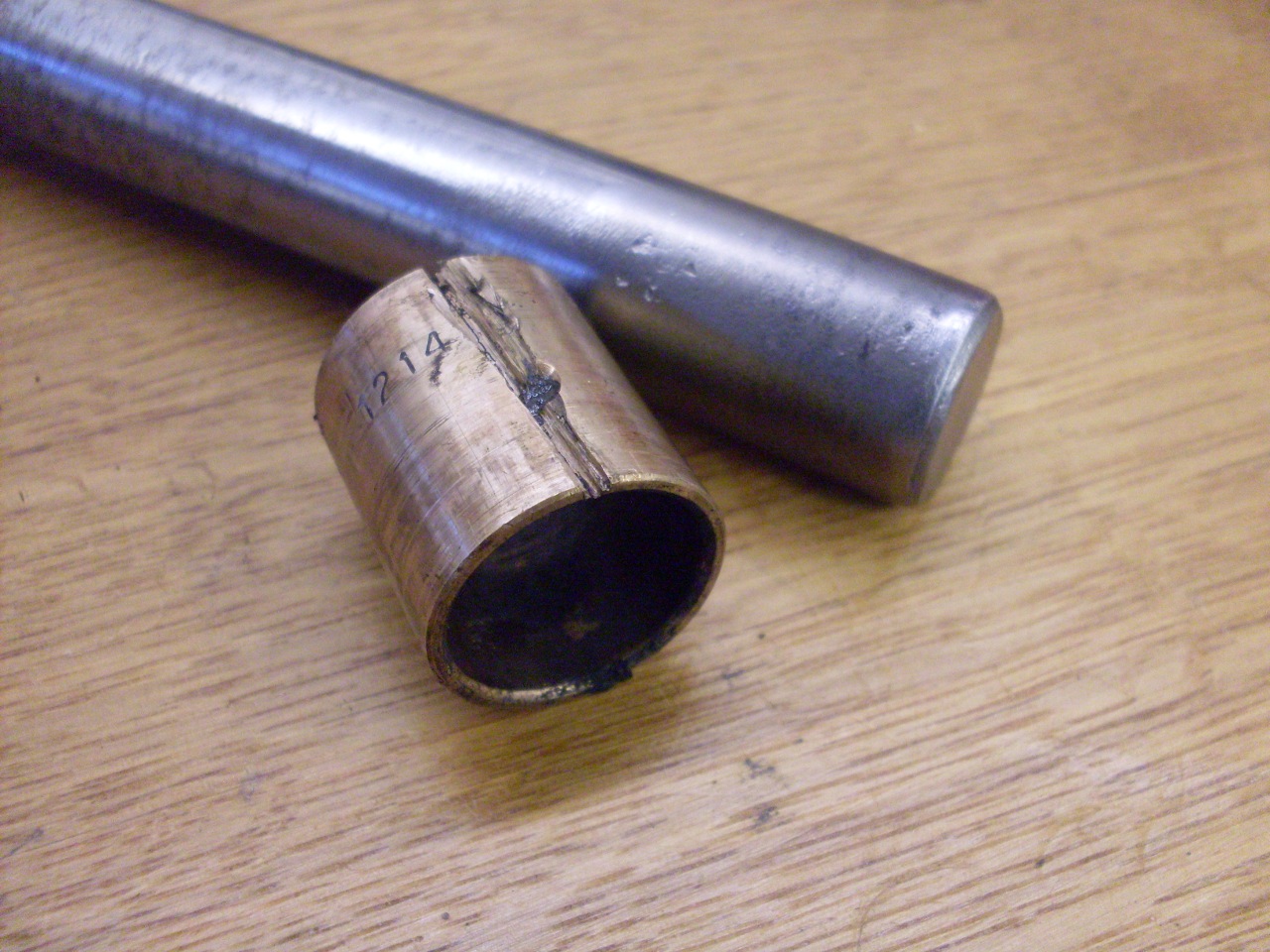
Back in the early 80s
when I had the transmission out to fix the third gear synch ring, I
also modified the bushes for the clutch cross shaft where it runs
through he bell housing. I took out the short steel bushes and
installed full length bronze bushes, and then drilled and tapped the
bottom side of the bush bosses for grease zerts. This seemed to
work really well for maybe a year until the clutch started getting
stiff and sticky. It would release OK, but was slow to engage.
It appeared that the cross shaft was binding in the bushes.
It finally got so bad that one day I pushed in the clutch and it
stuck there. I didn't have time to fix it, so in the garage it
went. My theory at the time was that clutch dust mixed with the
grease and hardened. Fast forward 30+years, and it was still
stuck when I parted the transmission from the engine a few months ago.
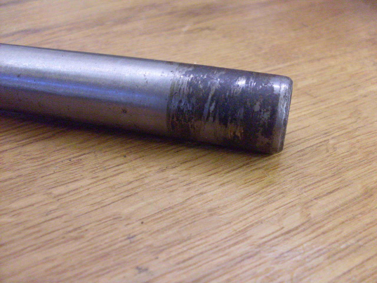
When I started working on the transmission a few weeks ago, the shaft would not
budge. I had to put a 3 foot cheater on the cross shaft arm to
get it to move. one bush was seized to the shaft and I had to cut
it off. This is still a bit of a mystery to me since I know that
earlier TRs had zerts for their bushes.
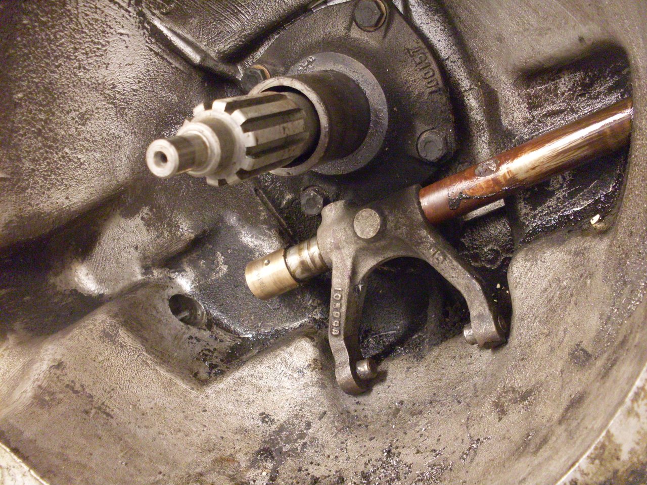
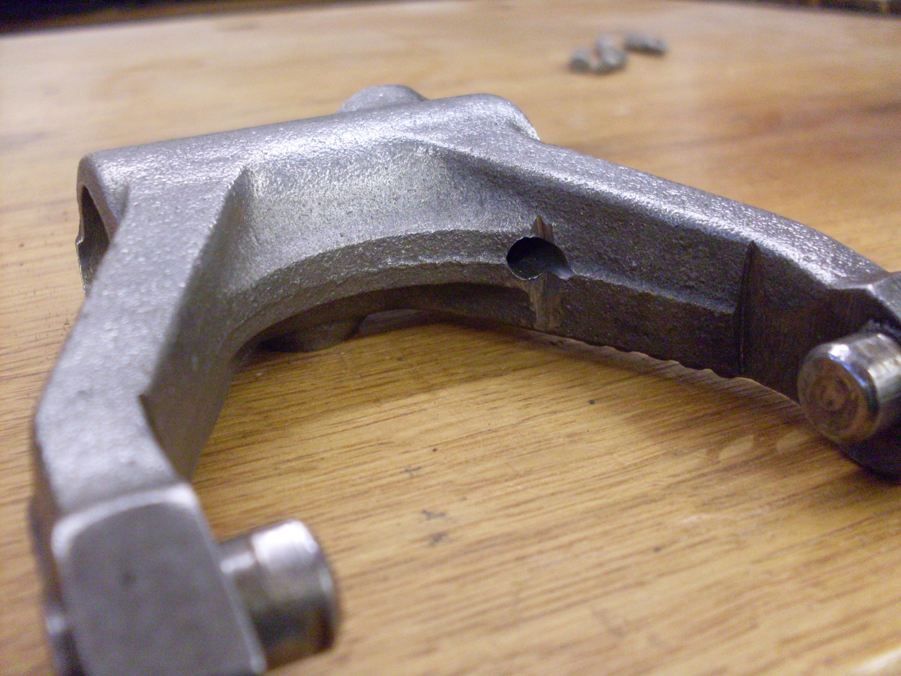
On
the way to removing the cross shaft, I encountered a heartache that
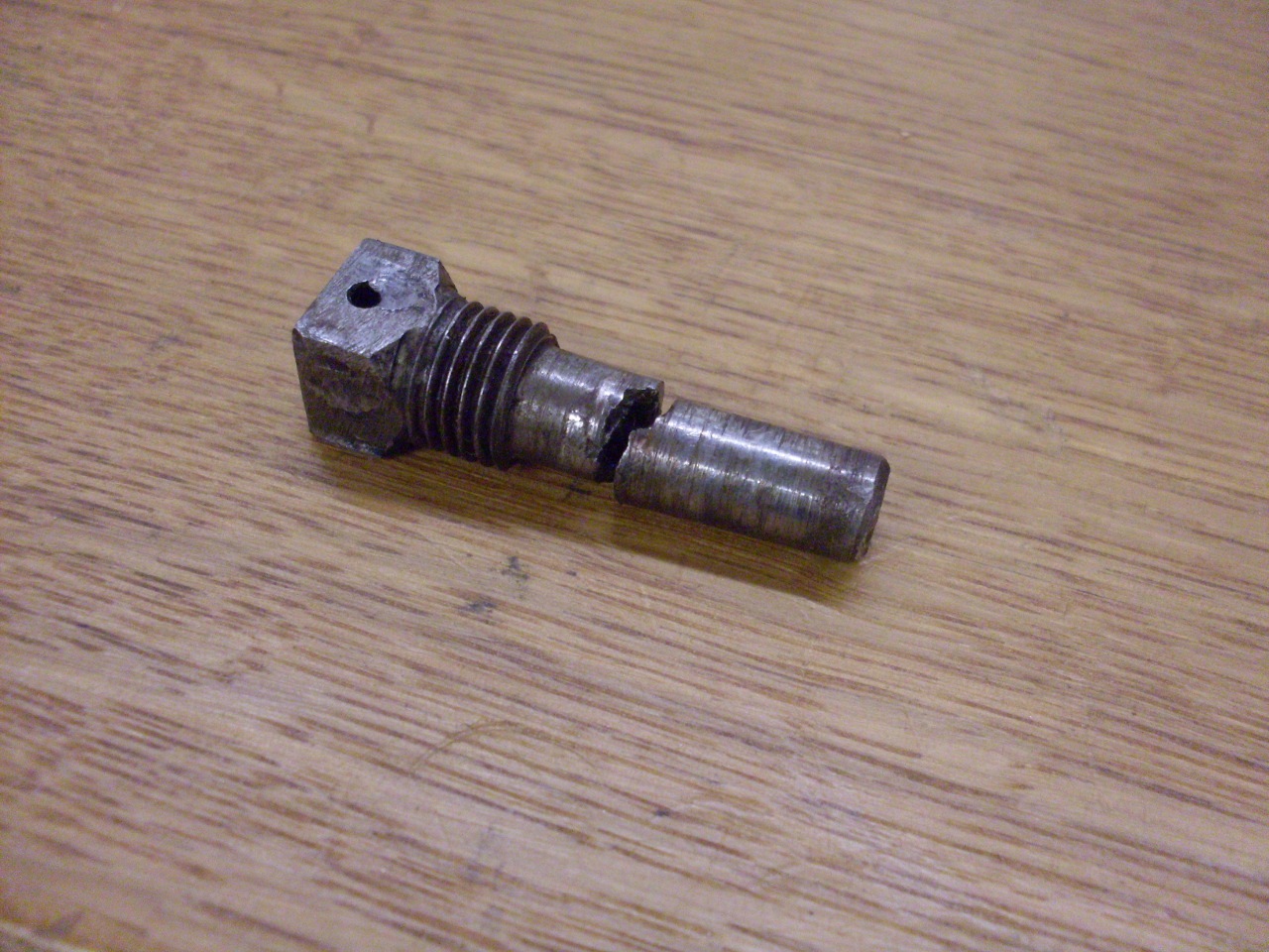
many TR owners know all too well. When I unscrewed the tapered
pin holding the fork to the shaft, only part of it came out. The
pin had broken in its bore and the lower part was keeping the fork from
coming off. This well known problem is caused by a bad design of the
bore for the pin. The bore in the shaft is tapered, but the bore
in the fork is not. This leaves the bottom end of the pin not
registered to anything on the fork so all the shear force is
concentrated at the upper intersection of the shaft and fork. The
pin can't take it, so it breaks.
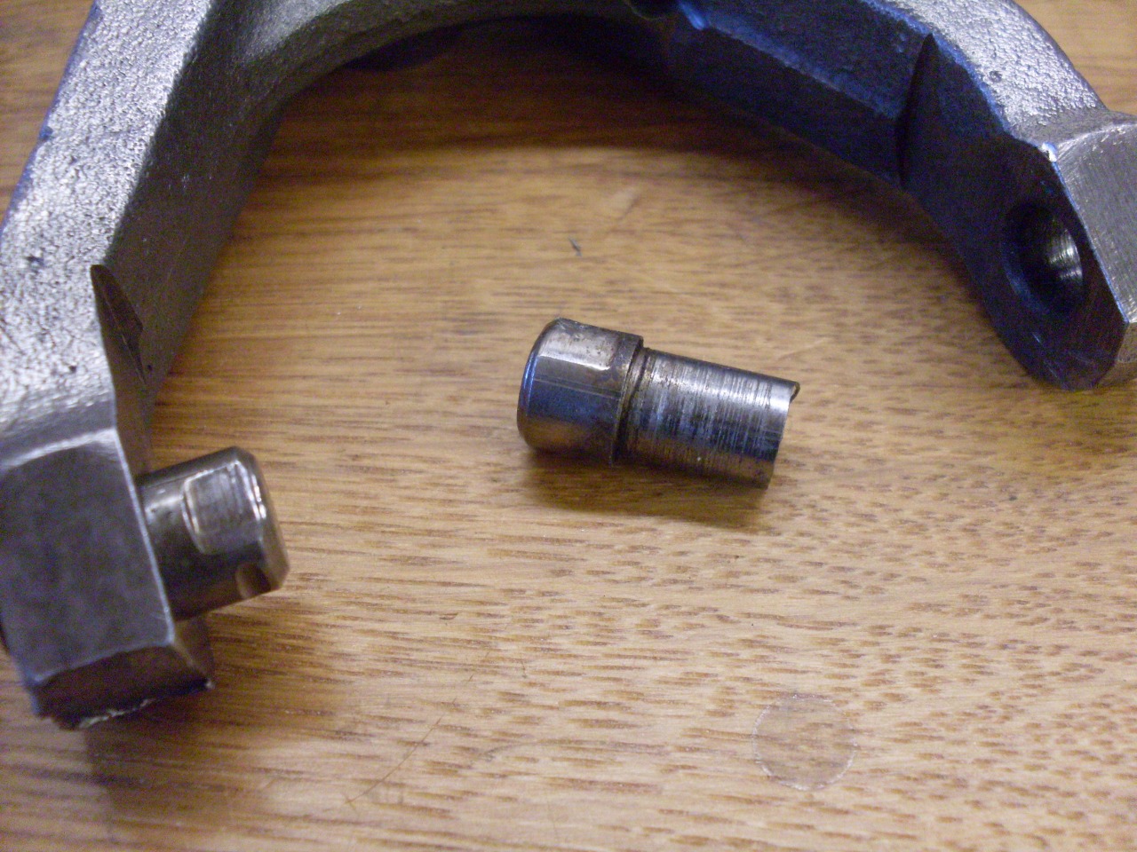
The most immediate problem was
to get the remains of the pin out so the fork could be separated form
the shaft. Since the shaft won't come out of the bell housing
with the fork on it, all operations to remove the pin had to be done in
the housing.
The solution, not original to me, was to drill a
small hole in the fork such that it would open into the bottom of the
tapered pin bore. This would allow a small drift to be inserted
to drive the pin fragment out.
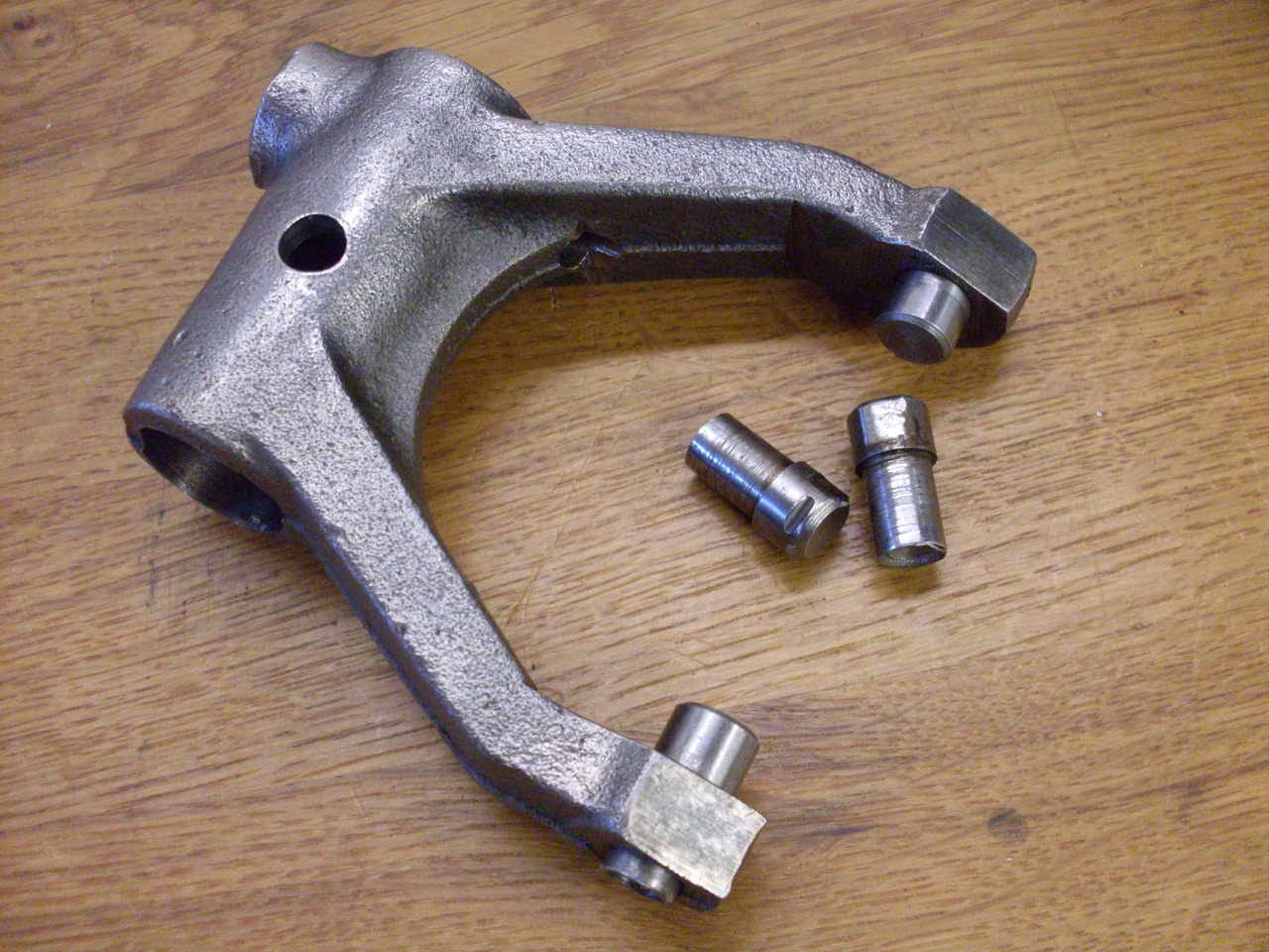
While
on the subject of the fork, it has two pins which engage a groove in
the release bearing carrier. These pins were pretty worn,
especially where one of them rests against the anti-rotation pin in the
carrier. These pins are replaceable, and are just driven
out, and new ones pressed in.
The
wear on the fork pins was matched by wear in the release bearing
carrier groove. There is a pin in the groove that prevents the
carrier and the inner race of the bearing from turning. Torque
transmitted by the bearing keeps the carrier up against the pin most of
the time, so the carrier wears in the areas where the fork pins rest.
The
wear bothers me, and if there were no alternative, I'd replace the
carrier. However, my mistrust of most aftermarket parts led me to
another option. Since the areas of wear are determined by the
position of the anti-rotation pin, it seemed simplest to just move the
pin. I drilled another pin hole 90 degrees from the original.
This renewal could actually be repeated quite a few times.
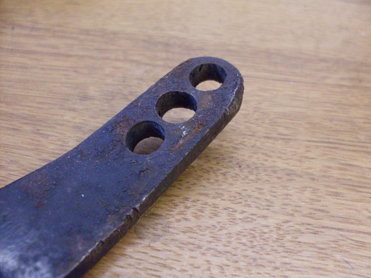
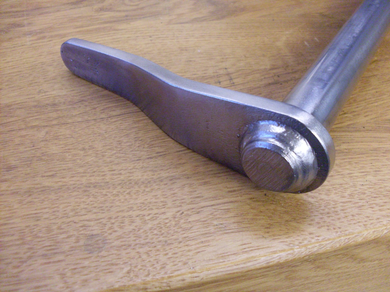
Another
area that was asking for attention was the arm on the cross shaft.
There are three holes in the arm to connect to a pushrod from the
slave cylinder, presumably to allow a little adjustment of the lever
ratio between the slave cylinder and the release bearing fork.
It's the middle hole that's nearly always used, and mine was
elongated. To fix this, I welded up all the holes, and just
redrilled the middle one. I've never even been tempted to use
either of the other holes, so they seemed superfluous.
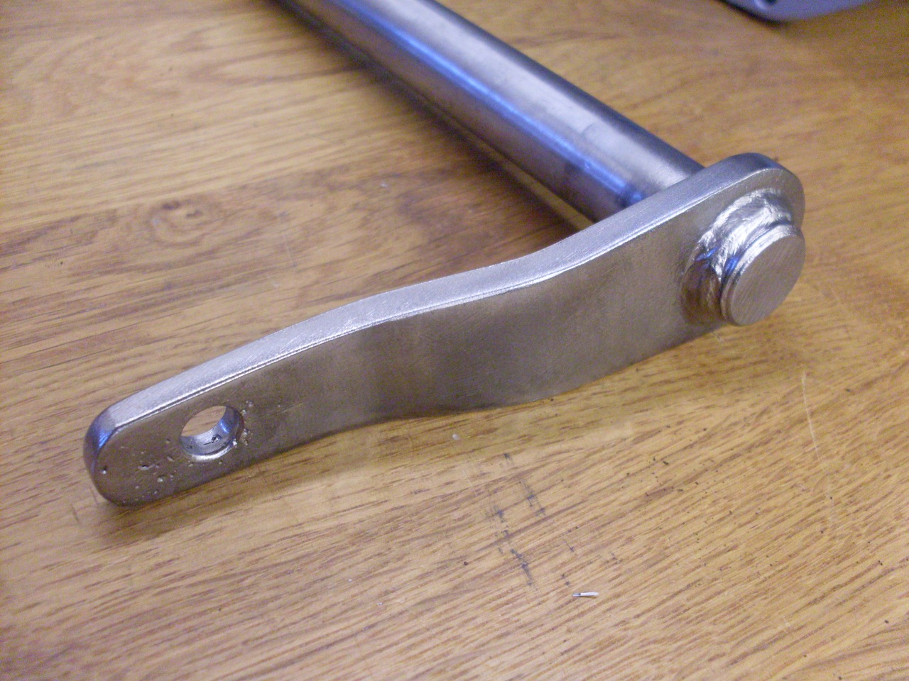

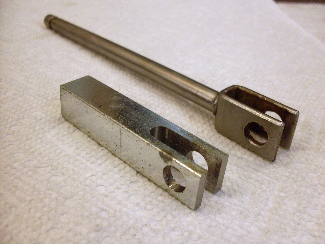
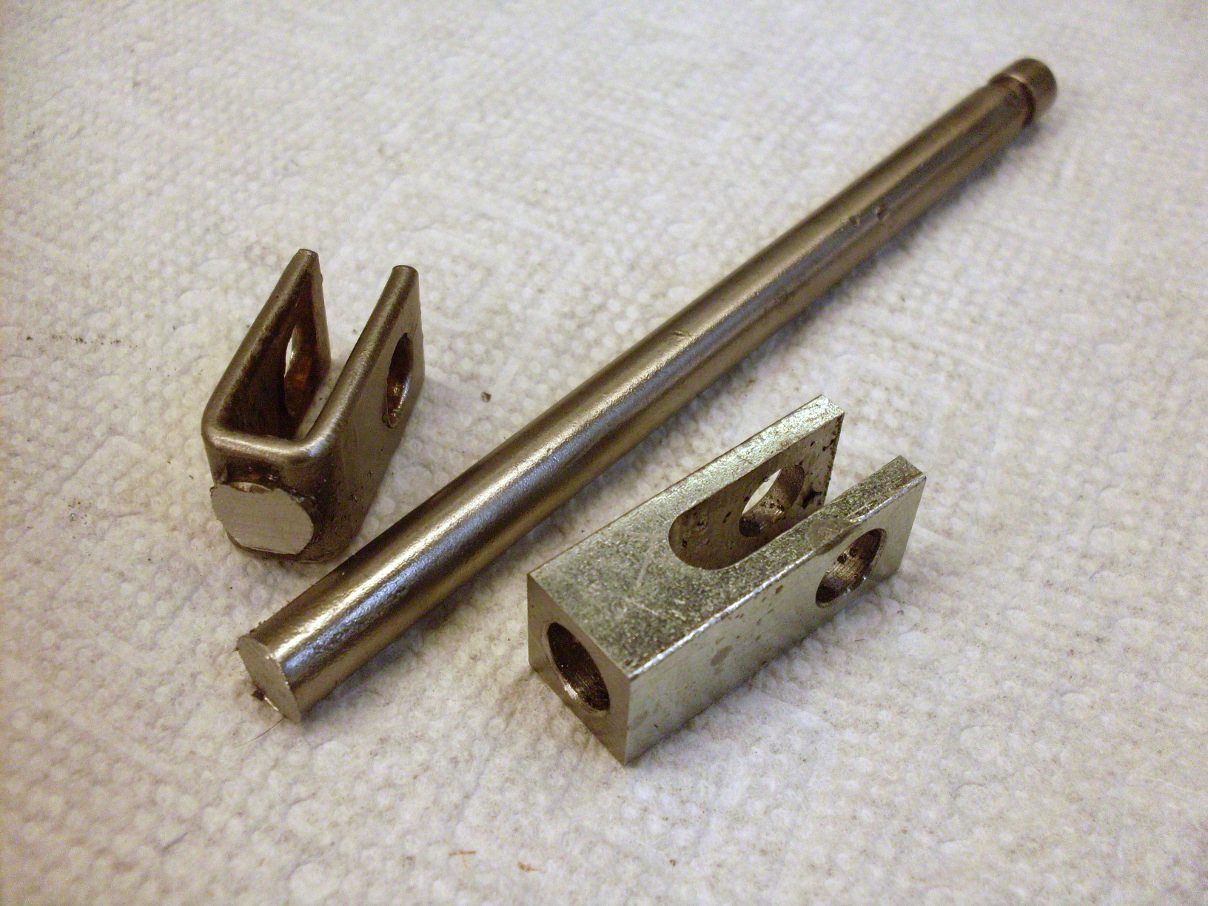
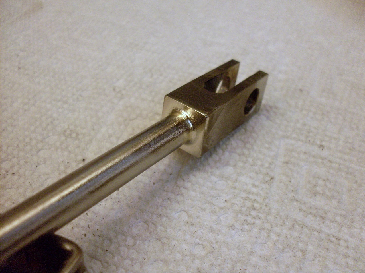
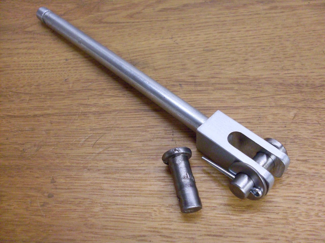
Next up was the slave cylinder pushrod. Like the cross shaft arm. its clevis holes were distorted.
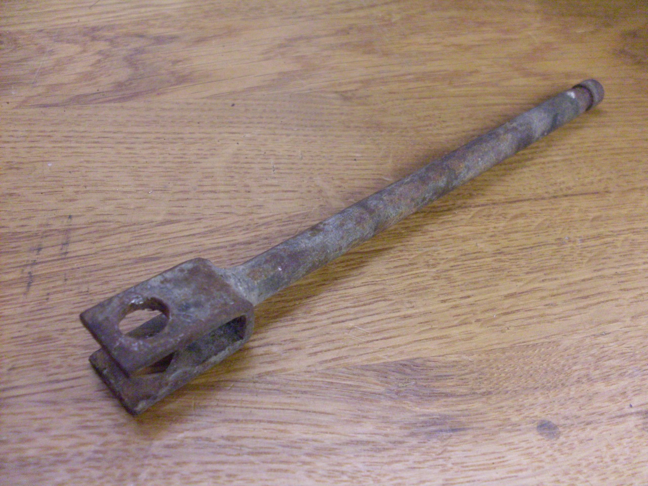
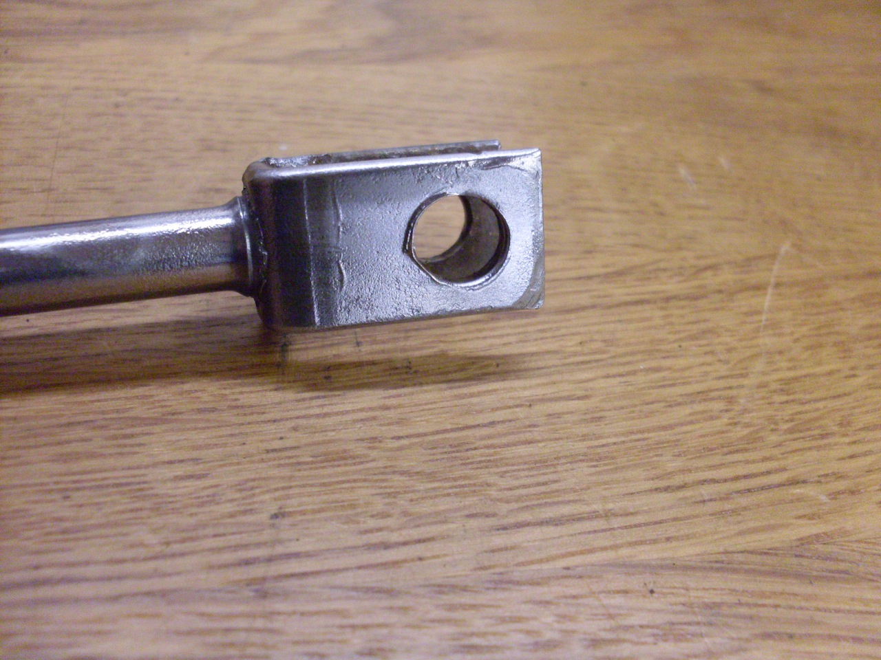
Rather than trying to weld up the rather thin arms on the pushrod, I
decided to just make a new, slightly beefier clevis end for the rod.
I'm particularly proud of that silver solder job. I don't think I've
ever had one come out that nice before. The last pic is after zinc plating the rod and making a new stainless clevis pin.
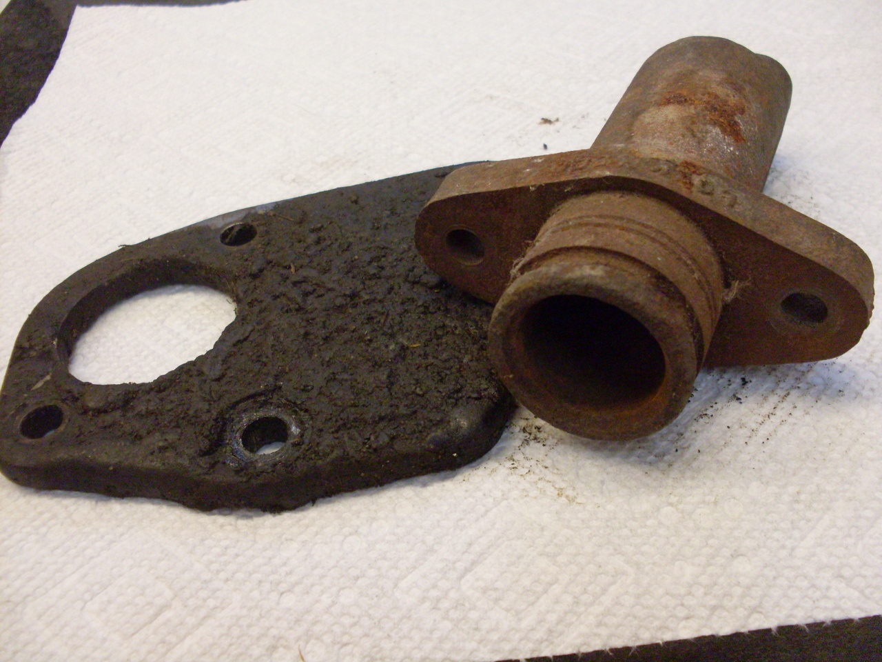
My
slave cylinder was toast. I think I took it apart back in the 80s
when I made a feeble attempt to diagnose the clutch problem, and it was
sitting under one of the seats for 30 years. It's bore was rusted
and some of the parts were missing.
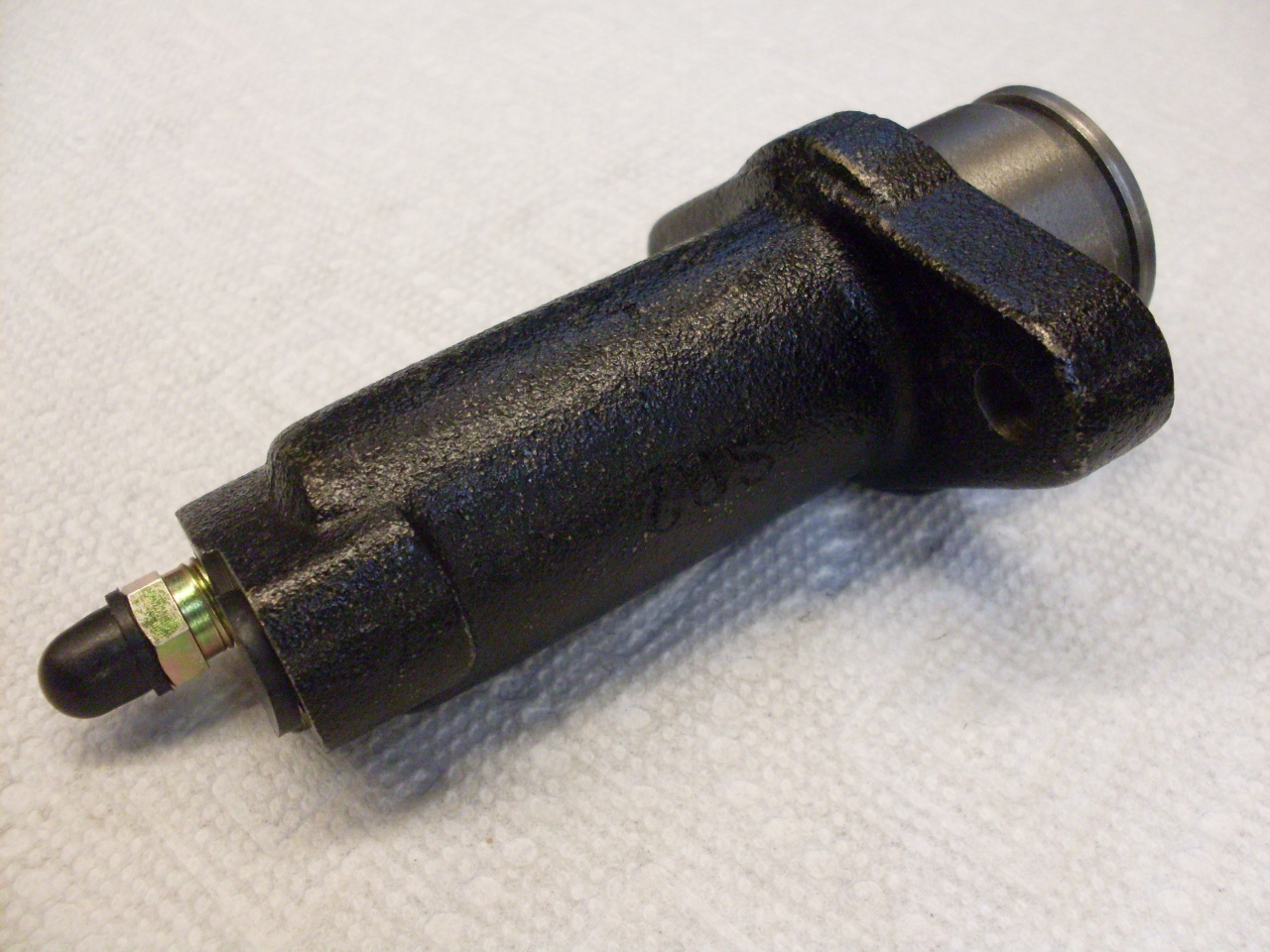
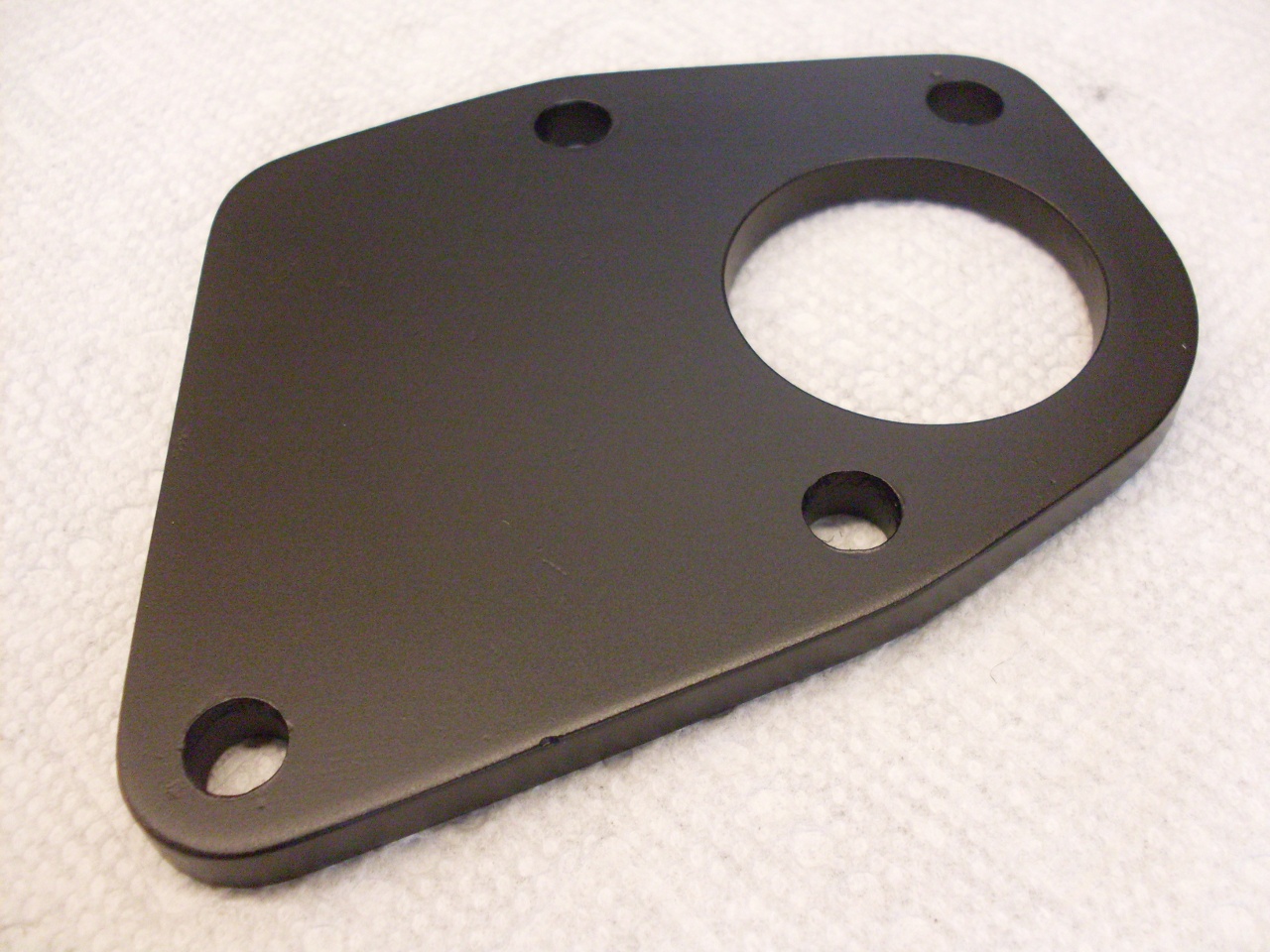
I
got a new slave cylinder. It has a smaller body diameter than the
original, but the one inch bore is the same. It had a pretty
lousy paint job, so I repainted it and the original mounting plate.

The
last job was to fix the design flaw that causes the taper pin on the
fork to break. There are a number of decent solution that have
been applied here. Some involve giving some support to the small
end of the stock pin, while others provide a second pin or bolt to take
some of the shear stress off the original pin. I found a nice
writeup on one of the TR6 forums that describes what I consider to be
an ideal solution. It consists of installing a new taper pin in a
fully tapered hole. There is even a boss on the fork that looks
like it was created for just this kind of solution. The thing
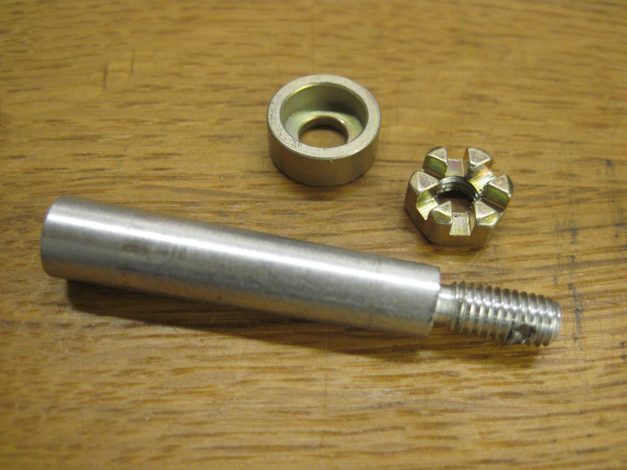
that makes this approach so sweet is the unique taper pin used.
The pin has a threaded section on its small end which allows a nut to
draw the pin in and keep it from backing out. Known as an "AN386"
type pin, it is most often used in aircraft applications (I believe the
"AN" identifies it as a military specification).
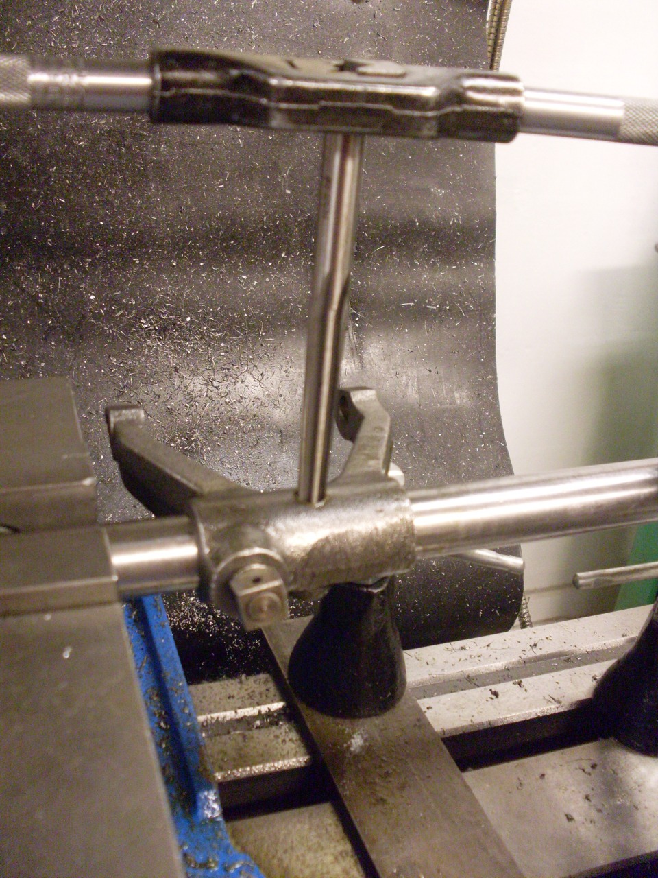
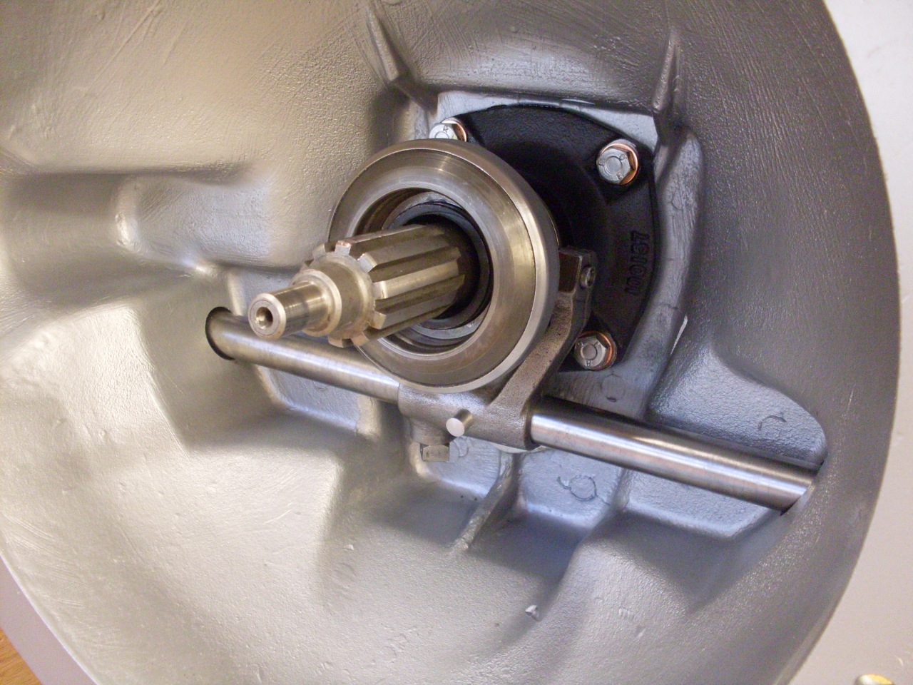
The
pin has a 1/2" per foot taper, and is compatible with a Brown &
Sharp (B&S) #2 taper. After screwing in the top remnant of
the original pin to locate the fork, I drilled through the boss on the
part so that the hole would be centered in the shaft. I then
followed with a slightly larger drill from the other side to rough out
the taper. The final taper was accomplished with a B&S #2
hand reamer. There isn't a much more accurate way to make a taper
pinned joint than this "in situ" process.
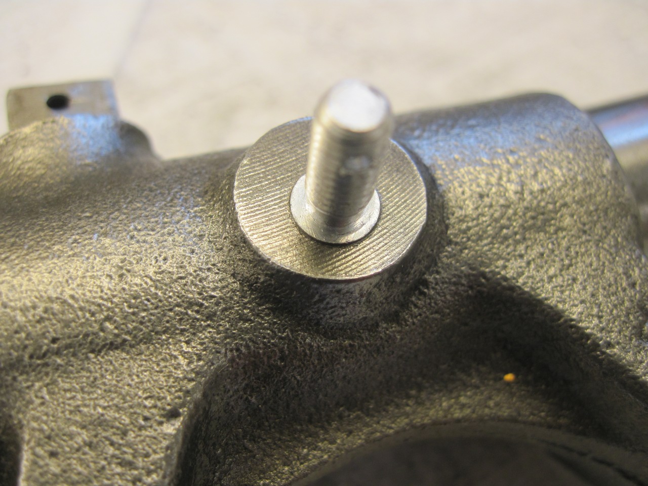
The
pin can be pushed in by hand, but the nut draws it in another 1/8" or
so. To guarantee that the pin is in full double shear, the bore
is usually sized so that some of the small end of the pin sticks out a
little when the pin is fully seated. That's why the special
recessed washer is used under the nut.
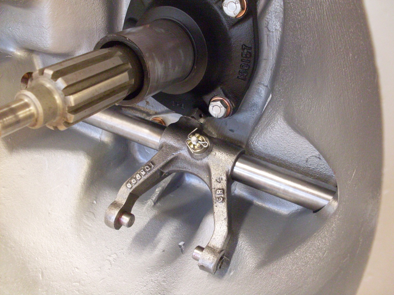
I
had ordered a new stock pin, and though I think the new pin makes it
redundant and unnecessary, I didn't see any reason not to install it
anyway. The tapered
spring goes on the shaft between the lever arm and the bell
housing. It is apparently no longer available, and mine was torn
up during the violence in removing my shaft. The one in the
picture was donated by a generous member of one of the popular TR6
forums.
Comments to: elhollin1@yahoo.com
To my other TR6 pages