To other TR6 pages
February 29, 2014
Rocker Geometry
Rocker
arms are dirt simple devices on one level, but the geometry of
their interaction with other components of the valve train can get
quite complex, and has a real bearing on the performance of the engine
and longevity of the parts. I did a fair amount of research on
valve train geometry to determine if there were any improvements or
adjustments I should make to my valve train, especially since I
shaved the head.
In many ways, rocker geometry can be viewed as
two separate problems--the geometry of the valve side and that of the
pushrod side. They of course are interrelated, but it simplifies
the picture if they are addressed one at a time at least to start.
Usually, the valve side is looked at first, since there are fewer
ways to adjust things there.
There are different philosophies on
setting valve train geometry, differing mainly in which parameters are
being optimized. One popular approach is known as "Mid-Lift".
In the Mid Lift paradigm, the rockers are aranged such that the
angle the rocker tip contact point moves through is centered on the
horizontal (this all assumes a vertical valve as we have in the Triumph
engines). Having a symmetrical path of the cotact point arc
implies several things: First, the side-to-side motion
of the contact point across the valve stem tip is minimized.
Second, the actual valve lift is maximized. Third, the
force on the valve stem tip is more nearly vertical.
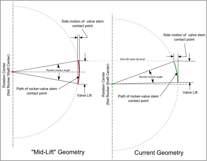
This
illustration shows the geometry I found on my head compared to what it
would be with a mid lift approach. The angle the rocker moves
through and the radius of its arc are the same for both situations--the
arc just occupies a different place in the circle.

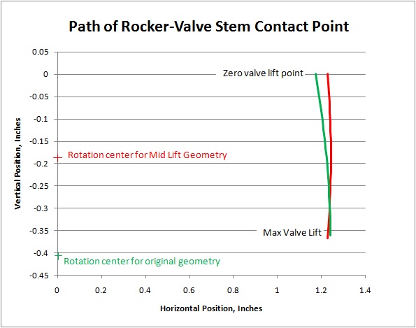
Here is the same information shown with the two arcs superimposed:

One
little complexity here is that the "rotation center" for the contact
arcs is not the rocker shaft axis. This is because the contact
point is actually on the radius of the shoe of the rocker, and the shoe
rotates through the same angle as the rocker, and so the contact point
moves outward on the shoe surface as the rocker rotates downward.
It turns out (and you can easily prove this if you know your way
around geometry and trig) that the rotation center is directly below
the rocker shaft axis by the radius of the shoe.
I was
serious enough about converting my valve gear to mid lift that I
calculated how much the rocker shaft would need to be raised (0.224"),
and made the appropriate shims for the shaft pedestals.

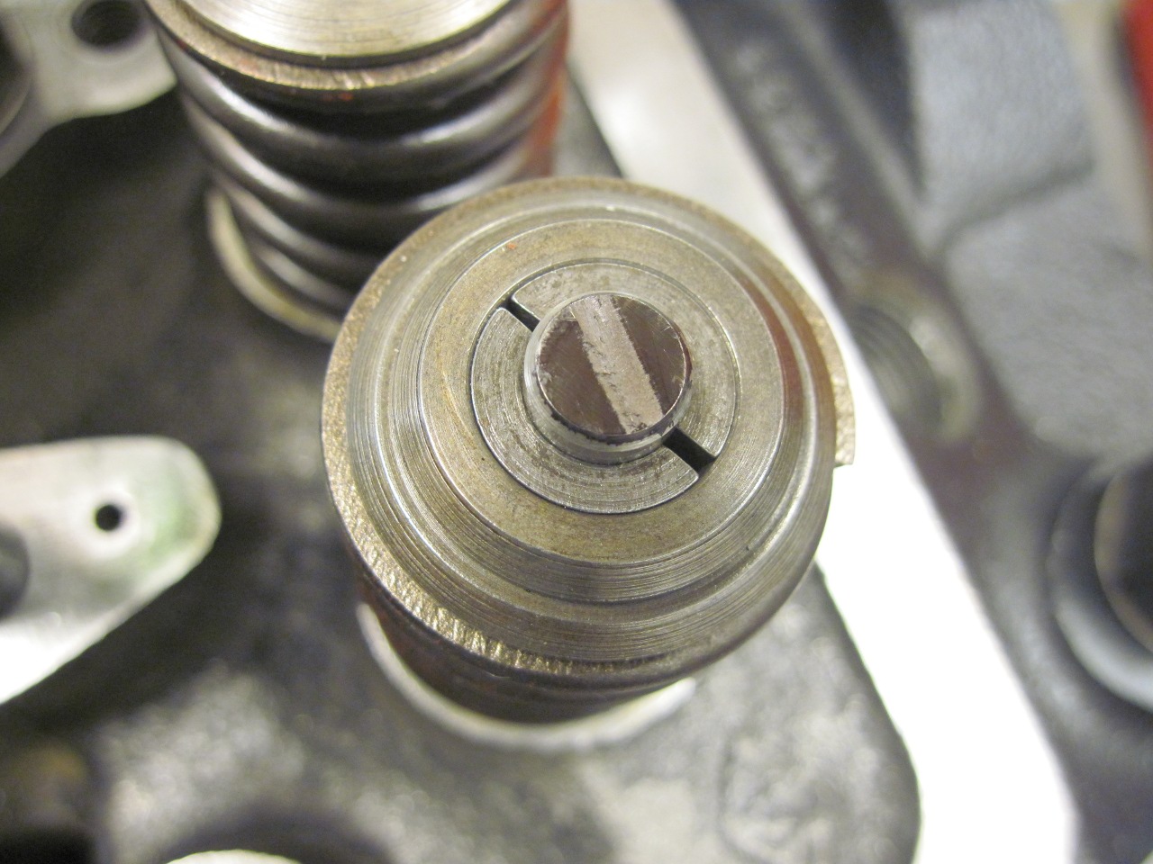
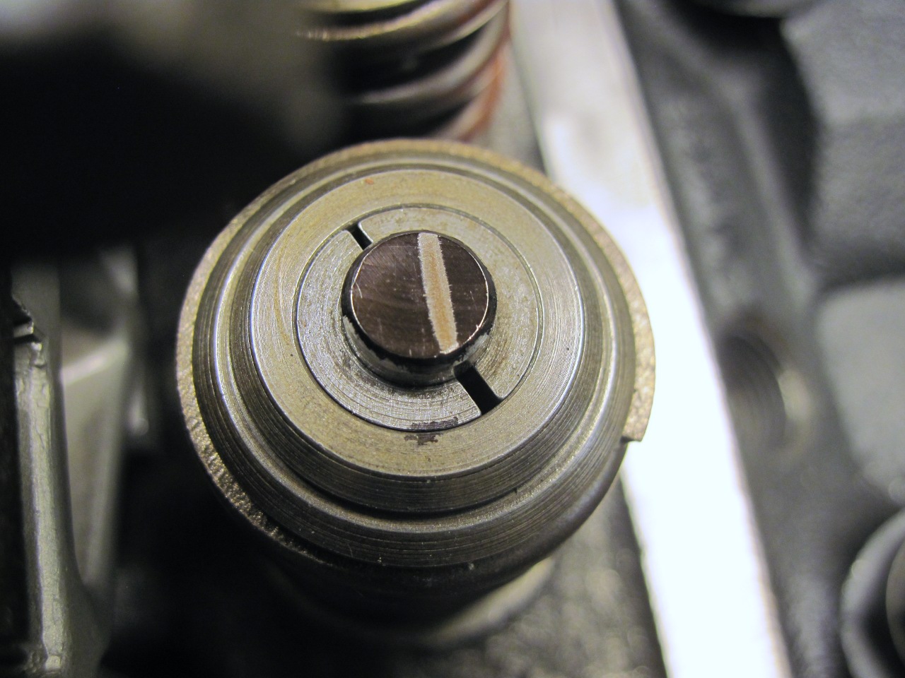
To
check some of the theory, I installed the shims and measured
the side motion of the contact point by bluing the tip of a valve stem
and rotating the crank a few times. The first pic shows the
pattern for the stock setup, the second for the mid lift.
As predicted, the mid lift pattern was skinnier and centered
slightly farther out than the stock pattern.


On
some hardcore racing sites, there is a holy war about how to interpret
these patterns. One camp categorically states that a centered
pattern indicates proper geometry. The mid lift folks counter by
saying that centering the pattern is not as important as minimizing
side motion and maximizing lift. Triumph Engineers were
apparently in the first camp (though, as I understand it, Mid Lift as a
design approach may not have been popularized until after the TR6
era).
In the end, I decided not to use the mid lift approach for
the following reasons. First, since the position of the valve
doesn't change, raising the rocker shaft raises the pushrod end of the
rocker even more, to the point that I'd have to find different push
rods, probably custom ones. Second, I realized that in both the
mid lift and stock cases, the rocker shoe does a combination of rolling
and sliding across the contact area on the valve tip. In the case of
the stock arrangement, most of the motion is rolling, with a little
sliding. With mid lift, there was almost three times as much
sliding. Maybe this is what the Triumph Engineers were optimising
for. Third, the pedistal studs would have been too short, and I'd
have to make or buy longer ones.
I think that if someone
is building for maximum performance, they might well consider a
mid lift approach, especially if they are using roller rockers, since
the sliding issue then goes away.
One thing became apparent to me while
going through this exercise is that fooling with valve train geometry
shouldn't be undertaken unless the side effects are well understood.
For example, it is commonly stated that when a head is shaved, rather
than getting shorter pushrods, the rocker pedestals can be shimmed to
compensate. The potential danger here is that this kind of change,
while possibly correcting pushrod-side geometry, will also affect the
valve side, which isn't otherwise affected by head shaving.
Comments to elhollin1@yahoo.com
To other TR6 pages

