To my other TR6 pages
March 29, 2019
Rear Stabilizer
TR6
cars, at least in '74, came with a stabilizer bar on the front
suspension, but not on the rear. A rear stabilizer is a popular
add-on for these cars, though its necessity, and even its advisability
is often debated.
A
stabilizer bar links the two sides of an otherwise independent
suspension system by transmitting forces that make the sides act more
in unison. This can make the car stay flatter in curves, but also
can affect traction negatively. The bars and the balance between
them can determine whether a car tends to understeer or oversteer in
conditions when side forces are high.
I
bought a rear stabilizer bar kit, advertized as suitable for the TR6, a
few years ago, and have gone back and forth on whether to install it or
not. My style of driving doesn't really test the limits of
traction much, so the understeer/oversteer question may be moot for me.
On the other hand, I do understand that in the rare panic
situation, a spastic suspension system could be dangerous.
In
the end, I decided to install the kit, primarily for the promised
flattened curves, but also to free up the storage shelf. If I
don't like it, or if it scares me, it's easy to remove.
When
I pulled it down from the shelf to look it over, I was not very
impressed. The actual bar looks fine, but the associated link
hardware made me sad.
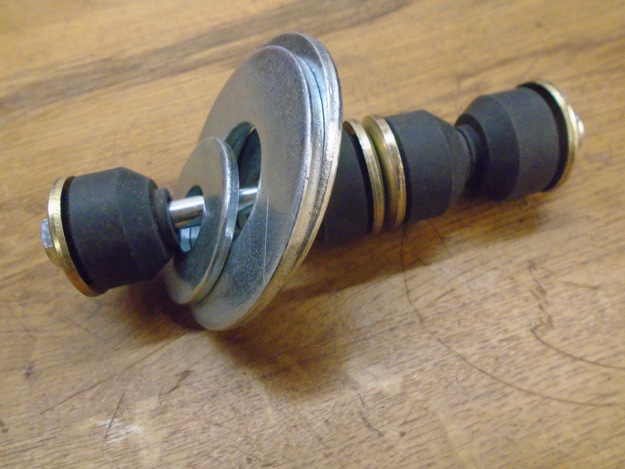
I
got the drift of how the link was supposed to work from the crudely
printed instruction sheet, even though its drawings didn't really match
the actual parts in the kit very well.
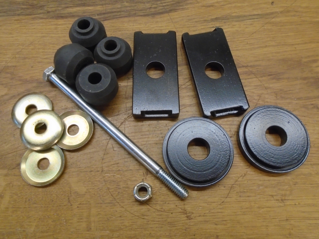
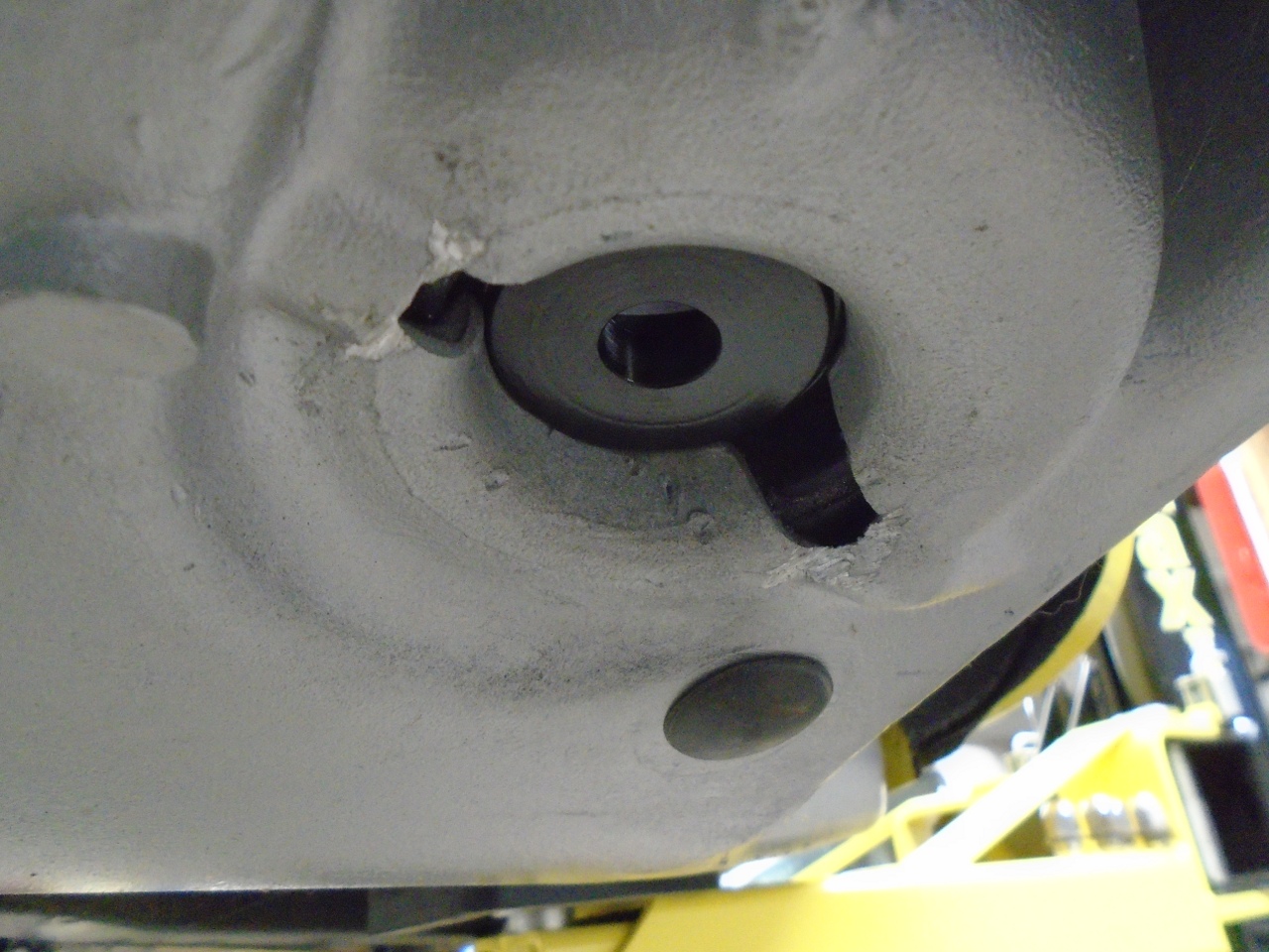
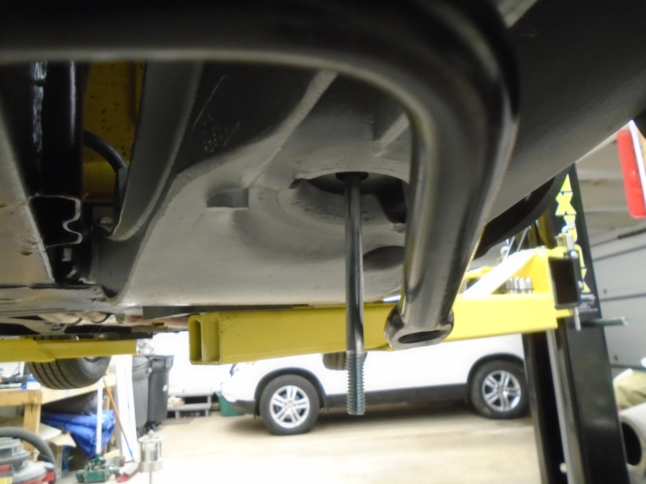
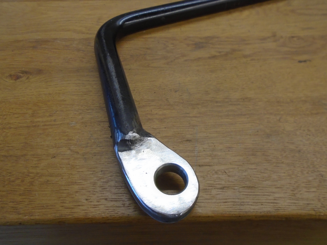
The
bar has a link at each end that connects to the trailing arm at the
round opening in the spring pan. The kit accomplishes this
connection with the usual rubber bushings, but just uses big stacked
washers to adapt the big hole in the trailing arm to the bushes.
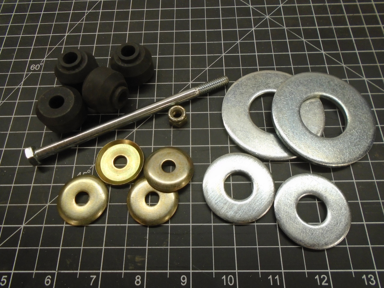
The hole in the small washer isn't even a great fit to the bushing.
Now,
I'm not totally ignorant of the cost pressures involved in putting
together a kit like this, but it seems to me that for the $160 or so
(as I remember) price tag, the maker should be able to afford some more
fitted hardware.
So at this point, my inner Engineer rose up, pushed me aside, and took over.
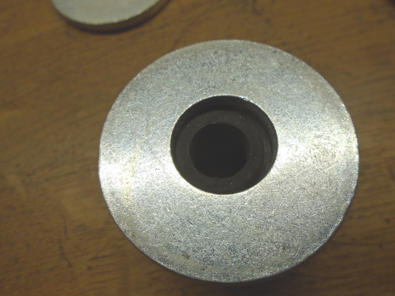
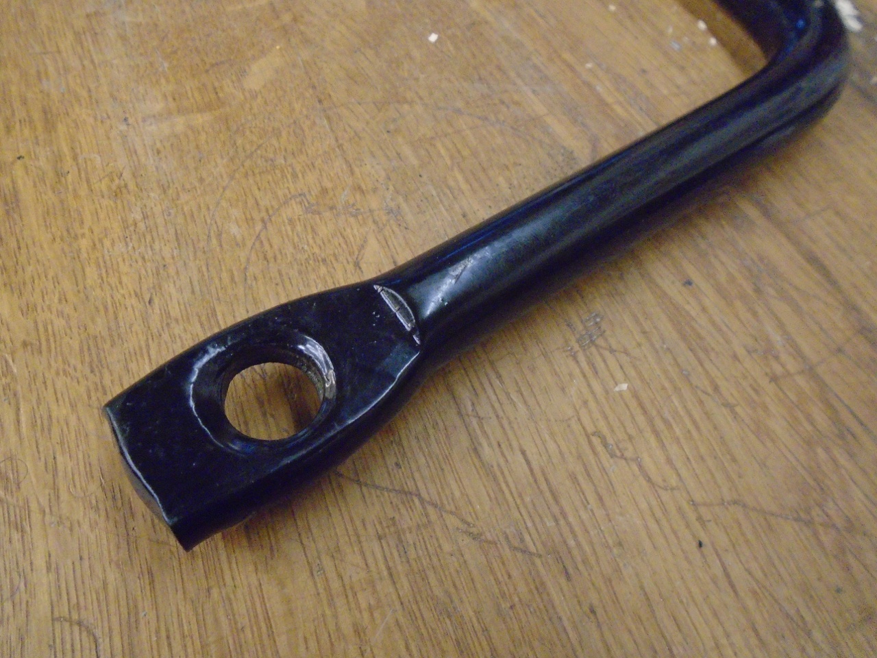
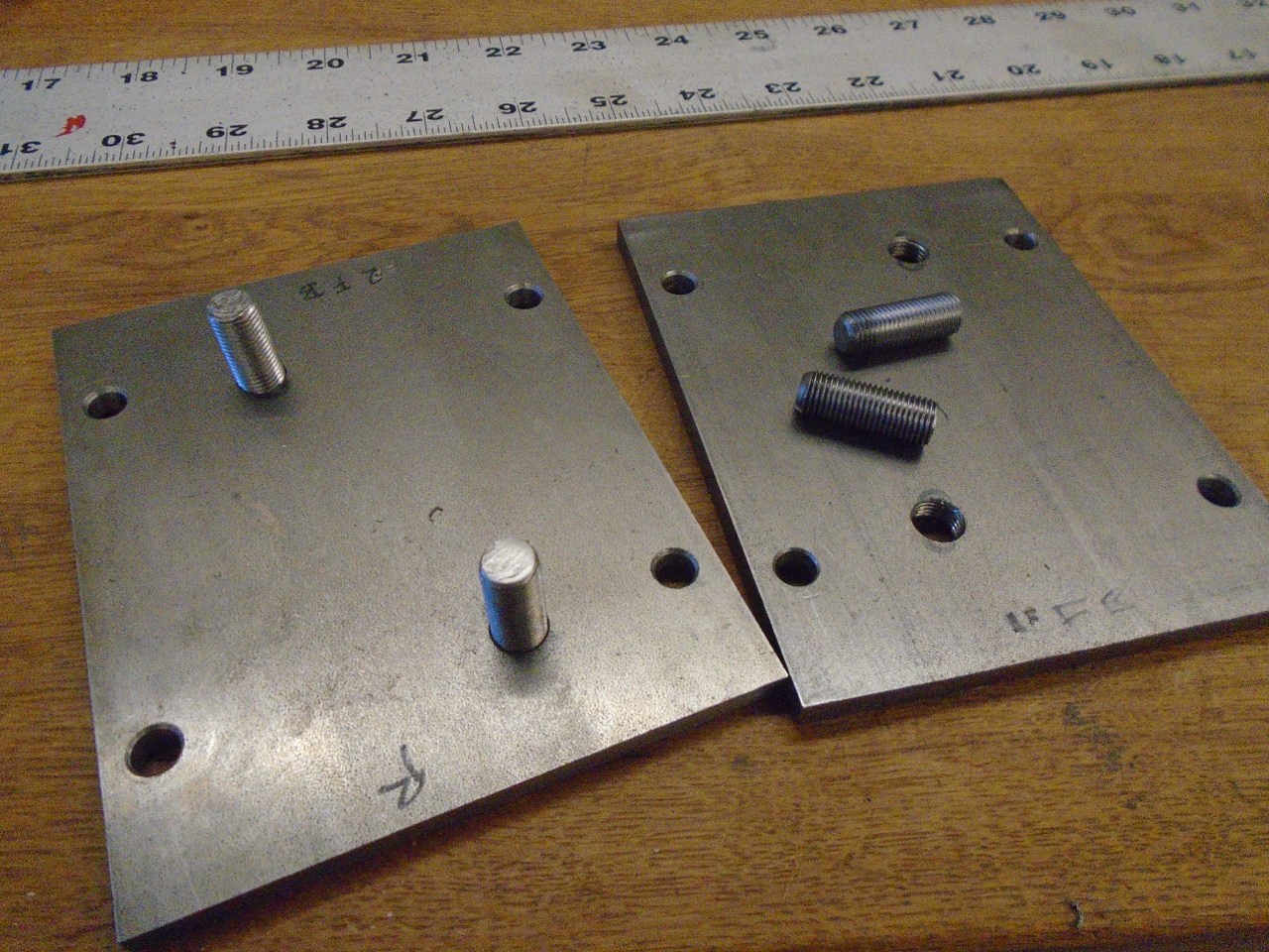
In
place of the washers, these new pieces will do the job. The
round one is a positive fit in the hole at the base of the road spring.
The bar spans the opening on the bottom side of the trailing arm,
and keys to the two little bumps on either side of the opening.
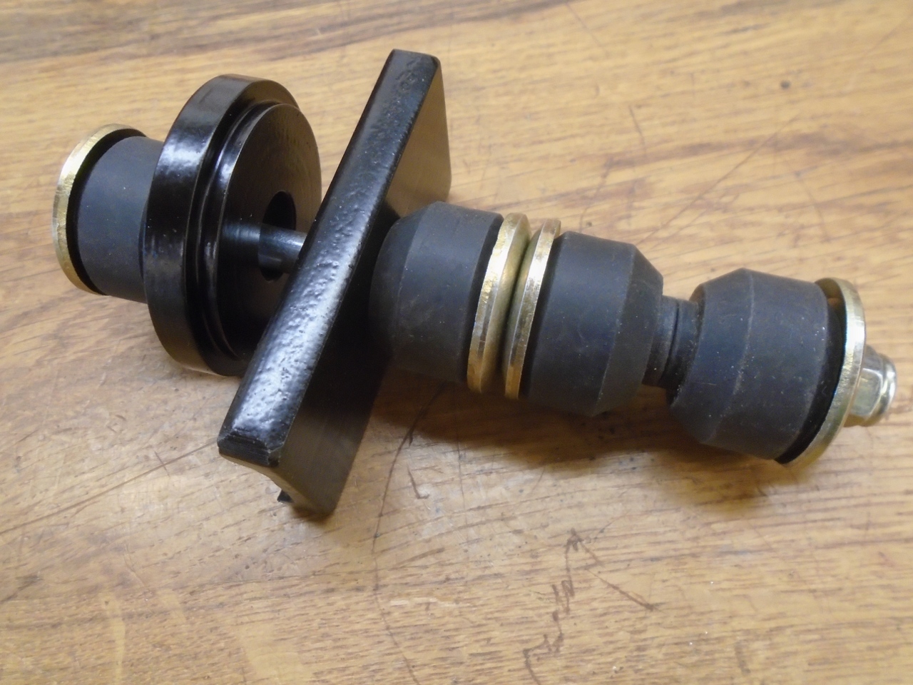
This arrangement uses fewer parts, is stronger, fits better, and is more corrosion resistant.
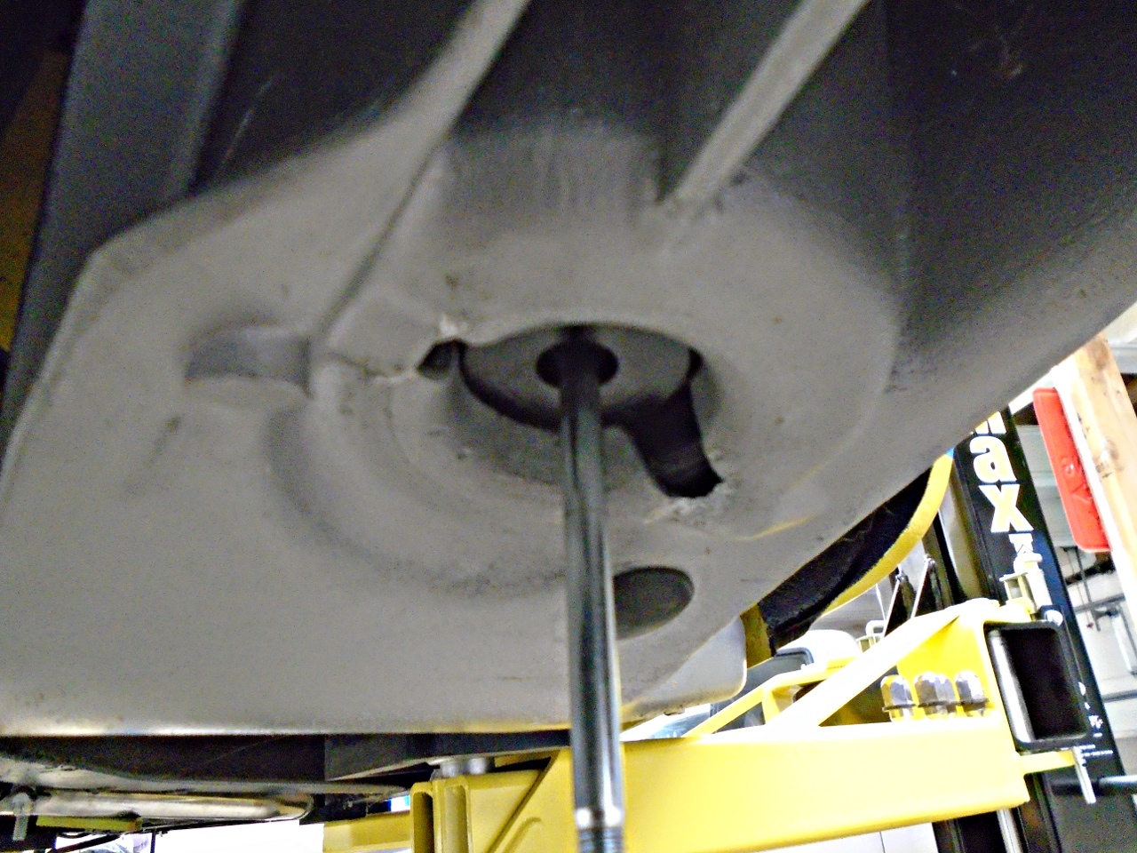
Great! So now that I had links I could be proud of, it was time to mount the bar.
Oops.
It
appeared that the bar was about an inch too wide to match up to the
links. I suppose I could have been shipped the wrong bar, but my
theory is that it is the intended bar, but it was barrowed from another
application, and the one inch mismatch was easily taken up by the
original more sloppy links. I could make the links go in the
holes in the bar, but all the parts were listing askew. I didn't
like it.
So,
now that my cocky inner Engineer had forced me into a corner, I had to
figure out what to do about the bar. I thought about trying to
bend the arms a little, but I wasn't sure I had anything hefty
enough to accomplish that. I could heat the elbows to assist the
bend, but it didn't seem like a good idea to mess with the temper of
what was essentially a big torsion spring.
"No, we just need to move the holes!" said the voice inside my head.
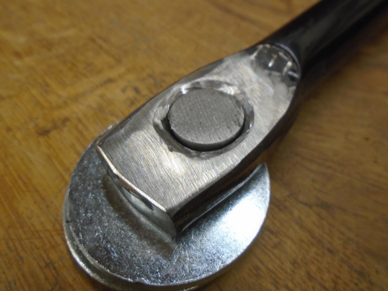
Inner Engineer took over again.
The holes were pretty rough, probably punched rather than drilled.
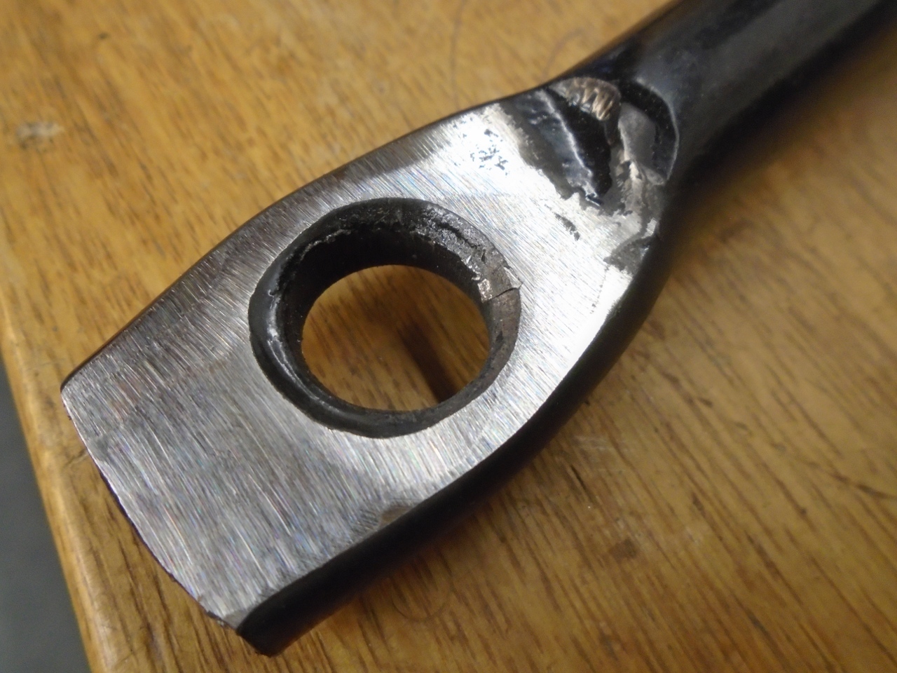
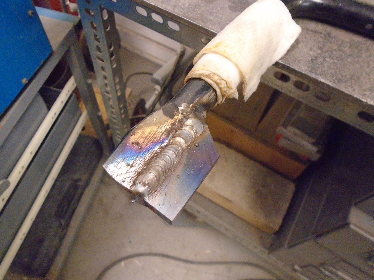
I cleaned out all the paint and fit a 5/8" slug in the hole...
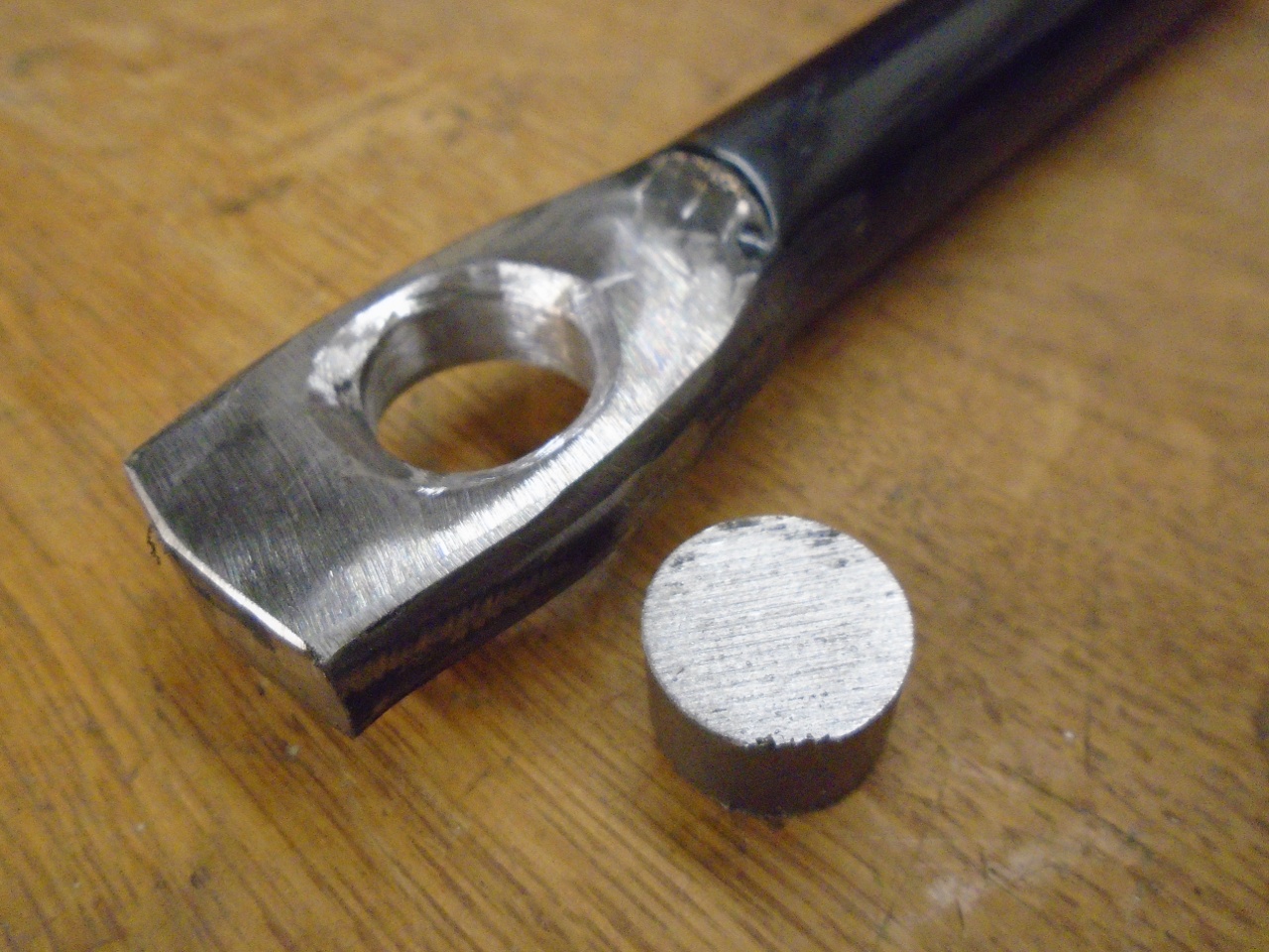
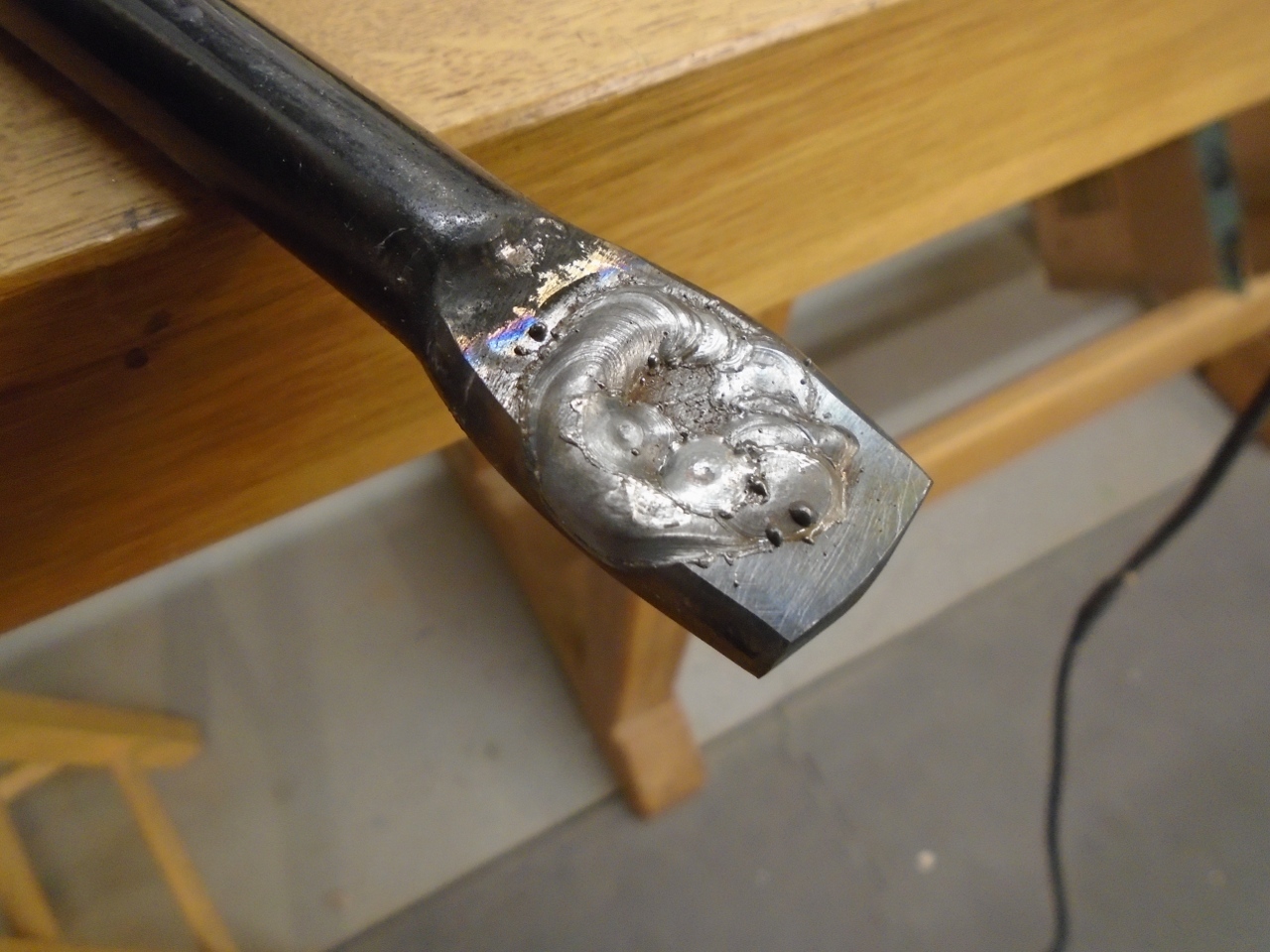
...and welded it up pretty deep on both sides. I tried to control the heat that went into the bar.
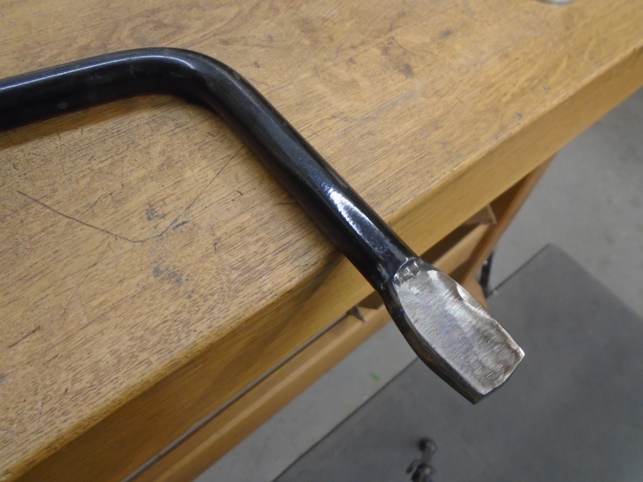
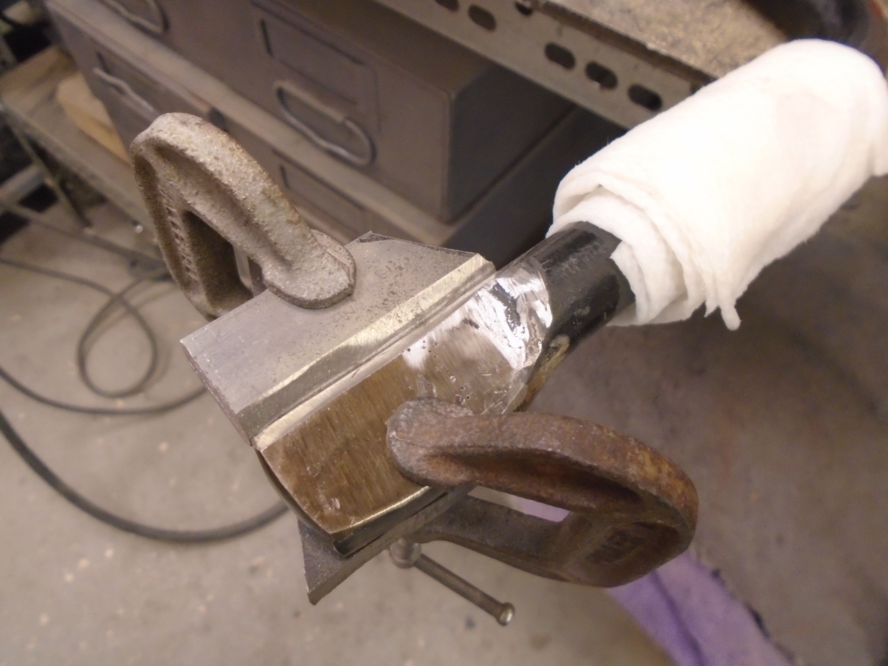
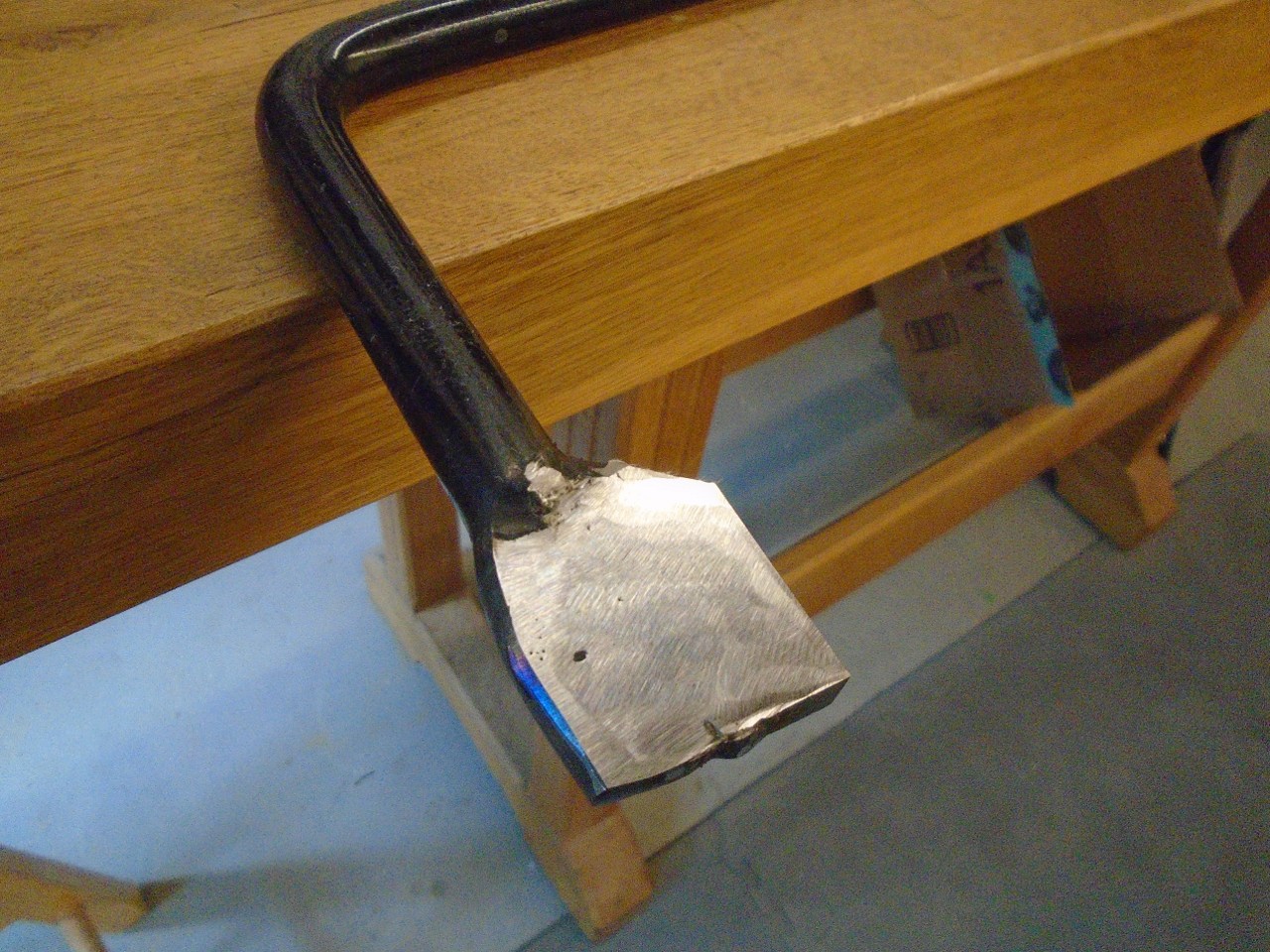
Then
added a little wing of metal on one side. The flat part of the
bar is about 3/8" thick. The wet rag wrapped around the bar is
for heat control. It worked well.
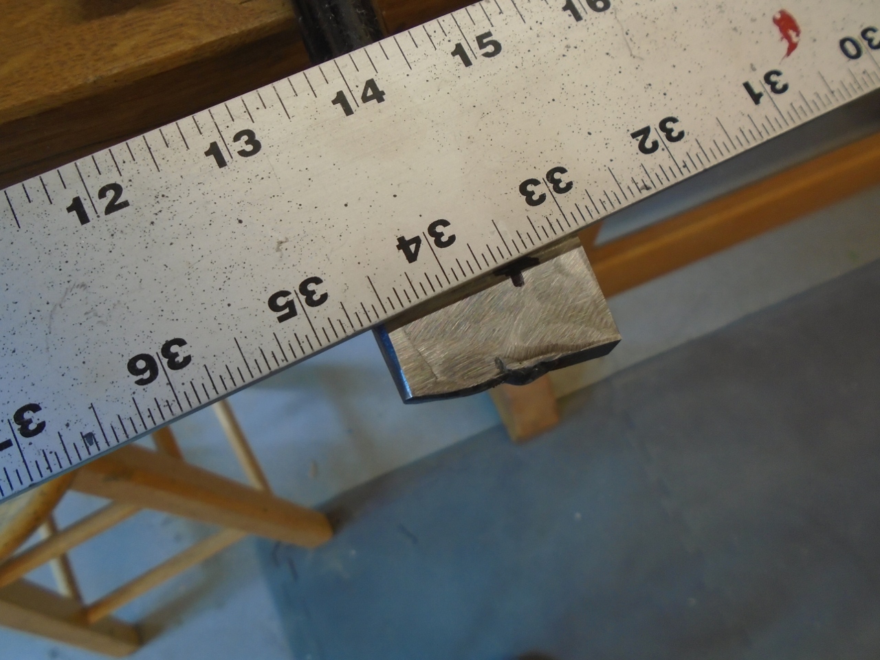
Then marked for the new holes. They needed to be 33.5 inches apart.
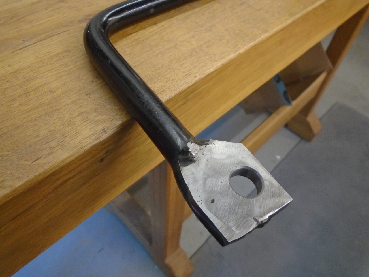
Then did a little shaping and painting for aesthetics.
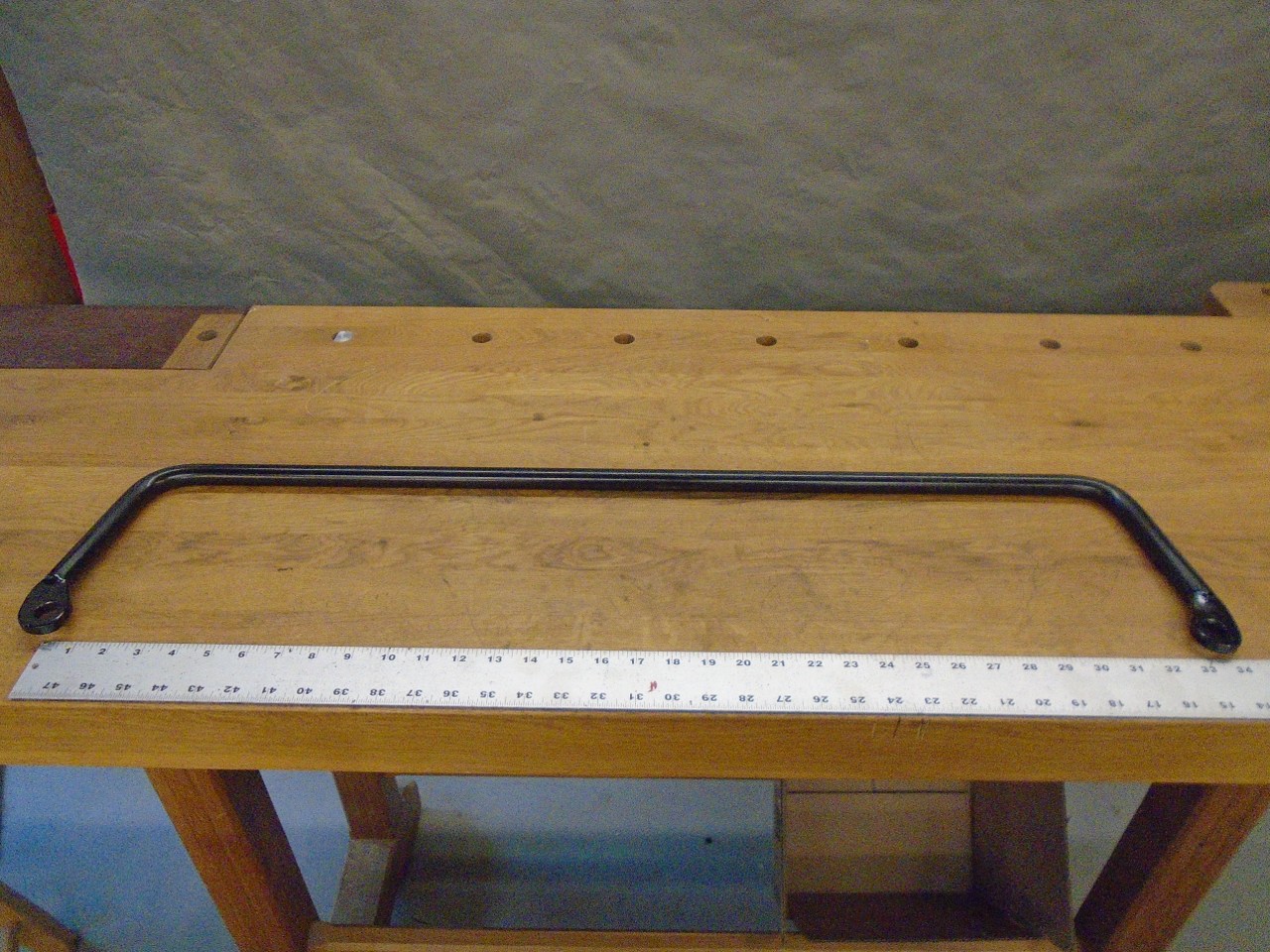
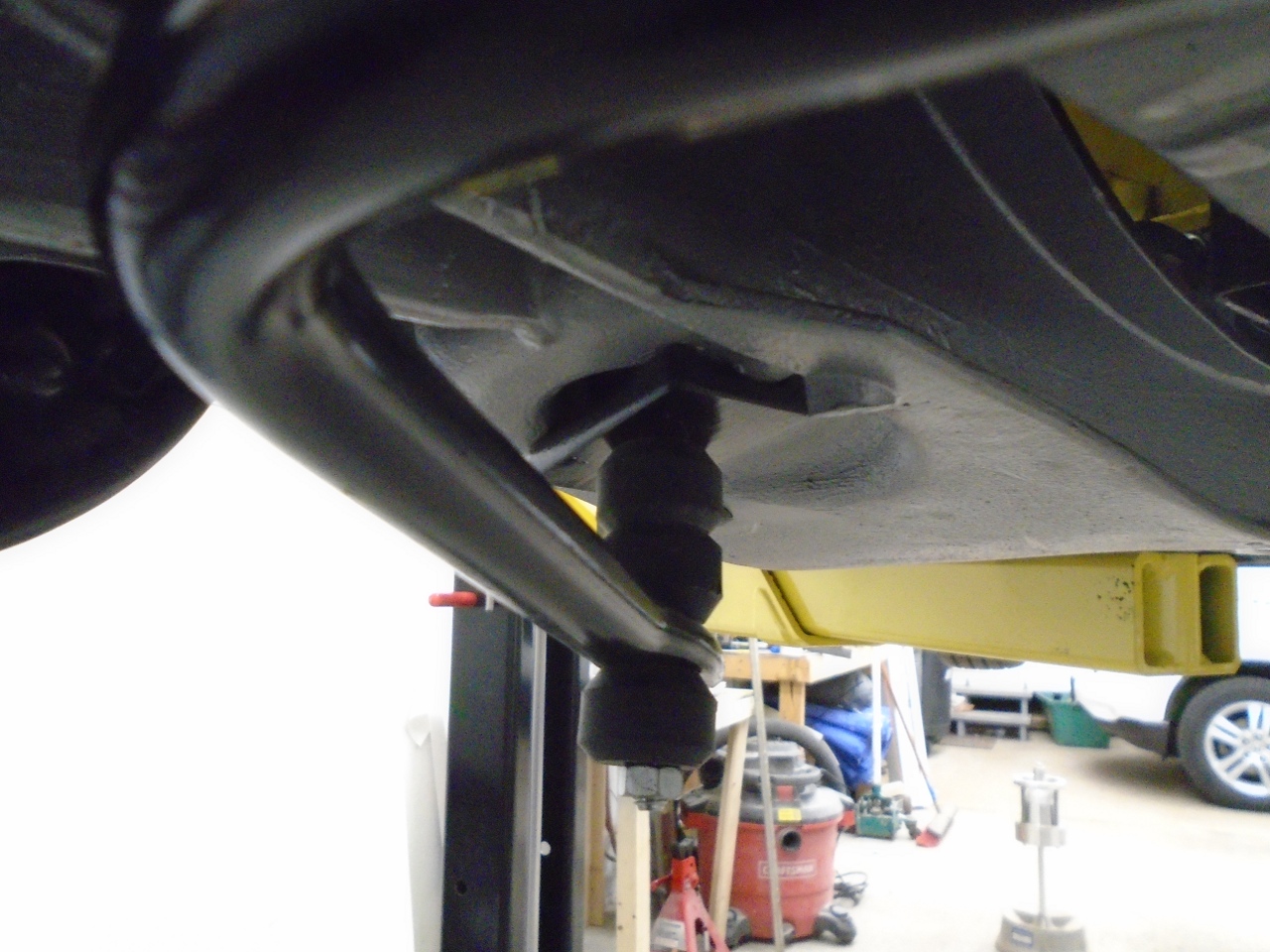
OK, now the bar fits the links.
So,
now on to mounting the bar to the chassis. The instuctions call
for drilling two holes on the bottom side of the frame rails on each
side. Through these holes a squarish, short "U" bolt is inserted,
which holds the bar brackets.
Well,
number one, I don't like drilling holes in my frame, especially for
something I'm not sure I'll keep. Second, though I've never heard
of a problem, it seemed that the entire stabilizer bar is attached to
essentially a single layer of sheet metal.
I heard inner Engineer whisper under his breath, "We can do better."
If
I had been considering the stabilizer bar before I finished the frame,
I would have welded purpose made pads to the bottom of the frame
rails, complete with studs for mounting the brackets. However, at
this late date, the frame was painted, and the inside carefully treated
with waxy rust preventatives. Welding could easily start a fire
inside the frame rails.
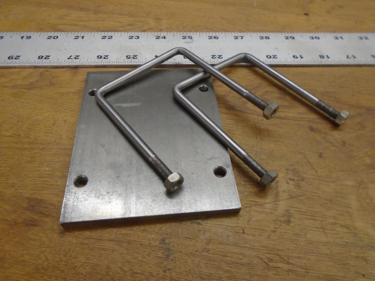
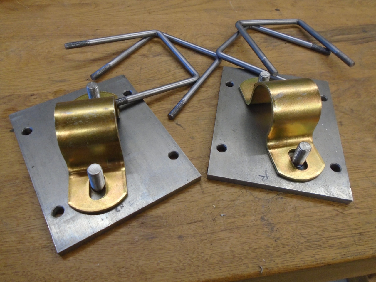
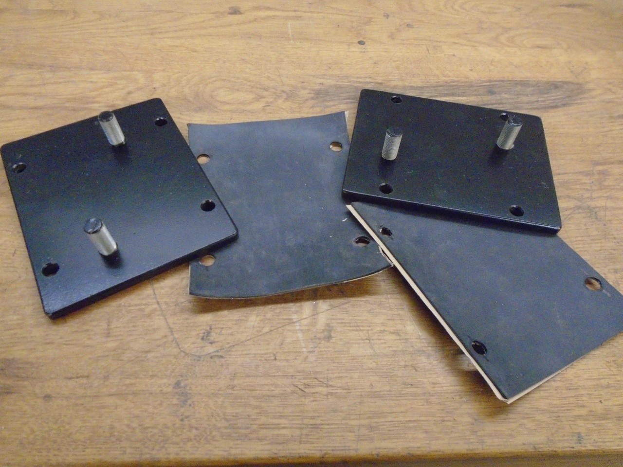
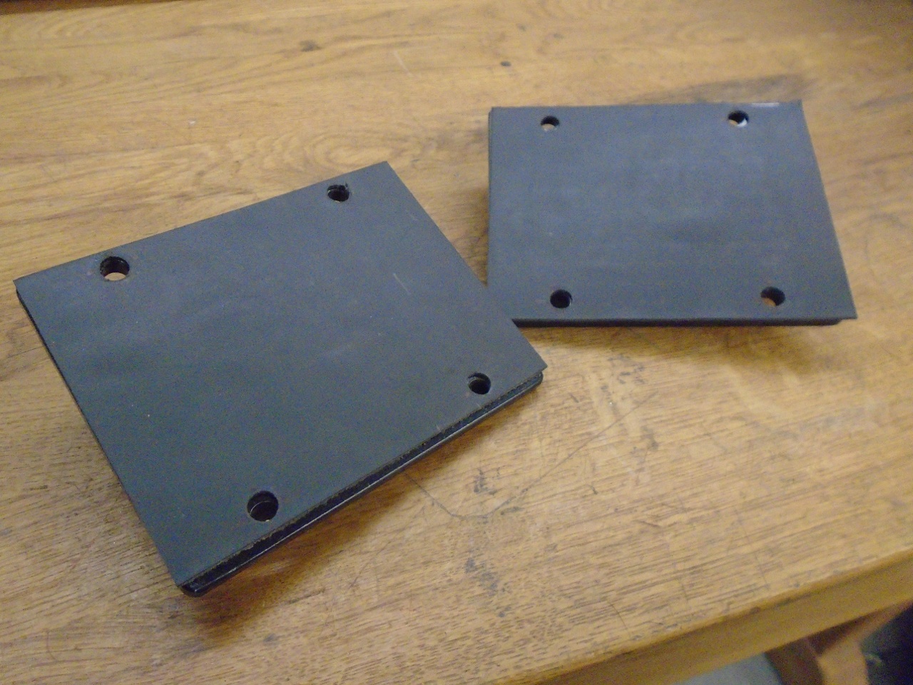
So, with welding options out, I
decided to mount the bar by clamping it to the entire frame rail rather
than just the bottom surface. I made an over-sized plate and some
square U bolts that would hug the frame rail.

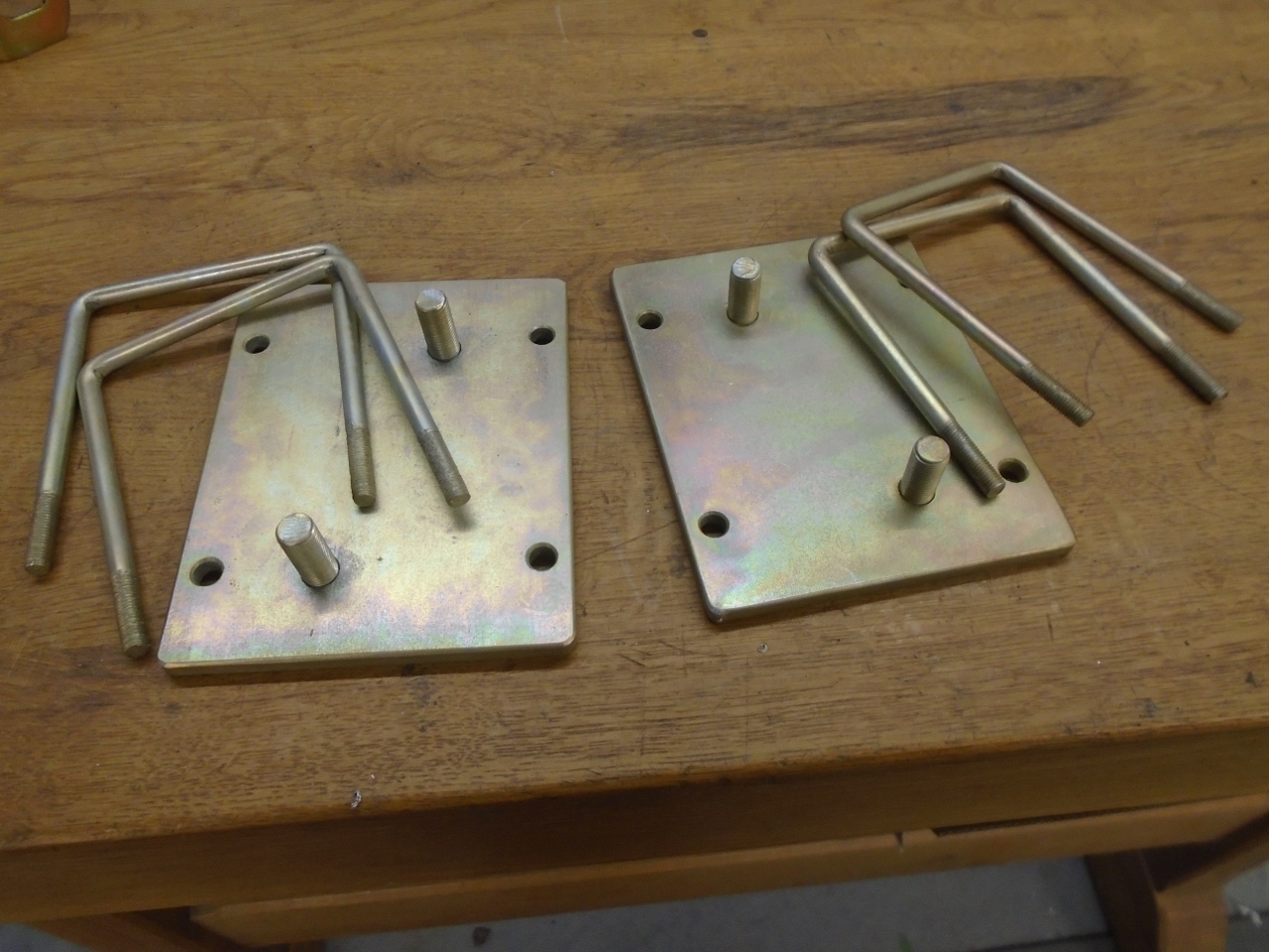
I
mounted the plates on the frame and marked where the bar brackets
needed to attach. Then drilled and tapped for some short 3/8"
studs, then welded them on the backside.

For belt and suspenders corrosion protection, chromated zinc plate and powdercoat.
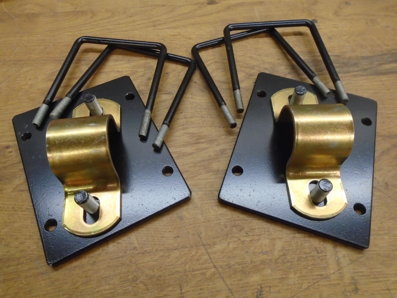
And a layer of rubber on the backside to protect the paint.
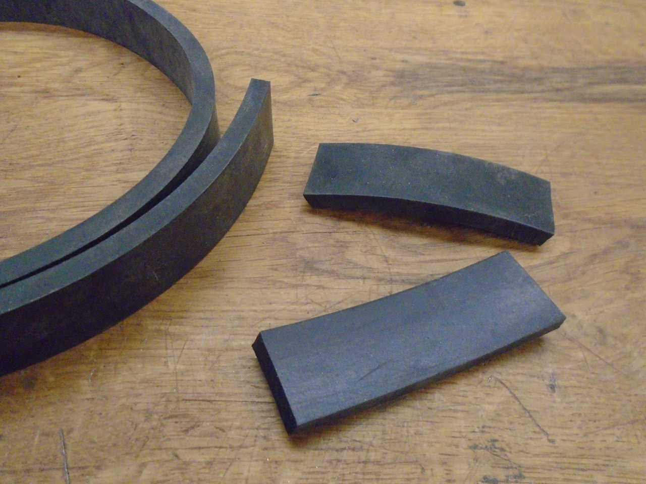
One
fly in the ointment here is that in the location where the bar brackets
mount, the bottom surface of the frame is not flat. This is just
where the upsweep of the rear frame rails starts. This causes the
extreme rear edge of the mounting plate to slightly hang out in mid
air. These rubber strips fill that gap and get compressed by the U
bolts.
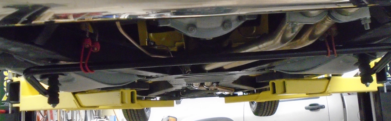
Dis puppy be done!
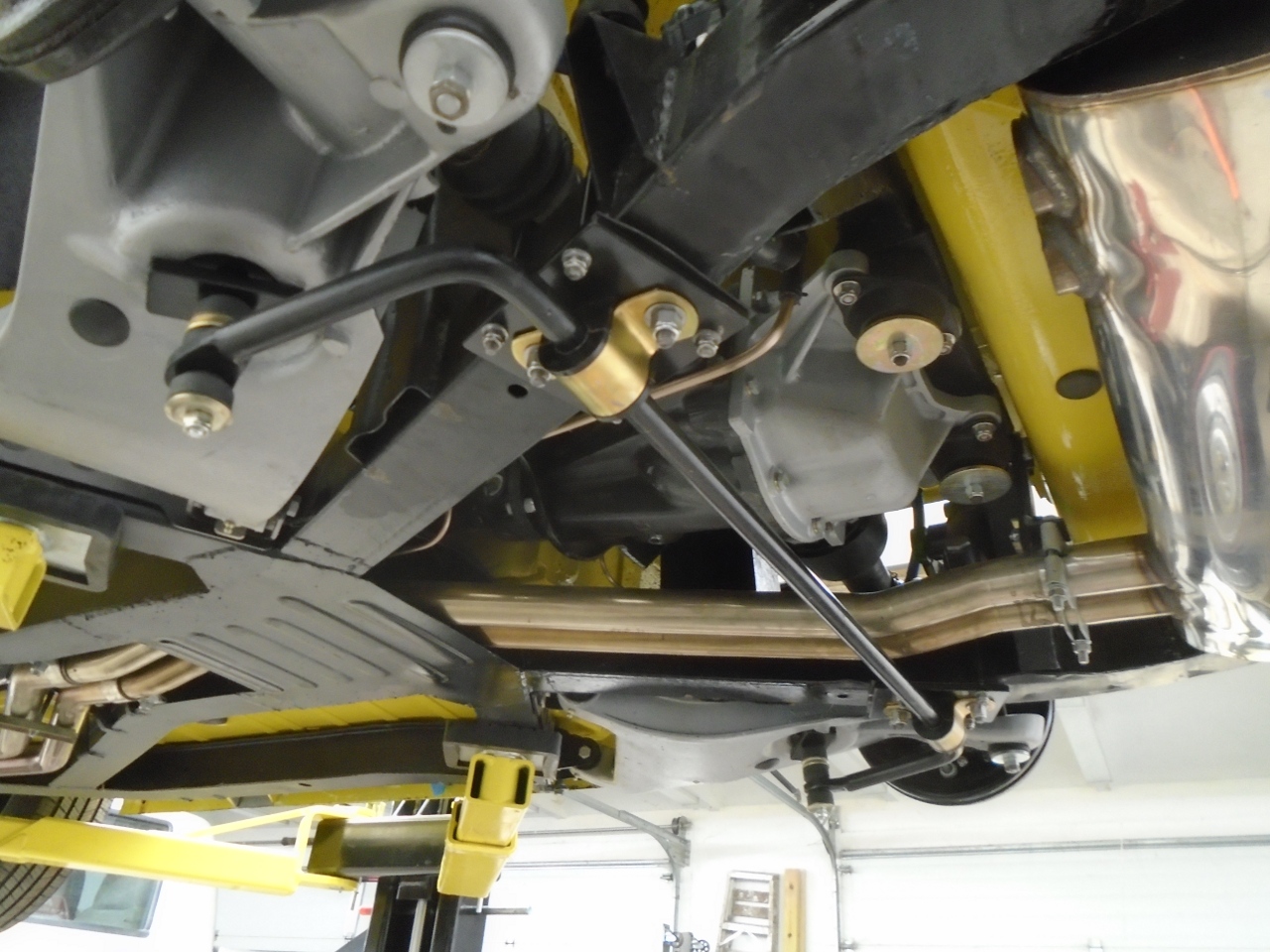
This
was a pretty fun project, but it was a fair amount of work for someting
that I might yank out in the future. Cost was pretty
much just whatever the bar kit was.
Comments to Ed at elhollin1@yahoo.com
To my other TR6 pages