To other pages.
December 28
Distributor
[Click Pictures for a Better view]
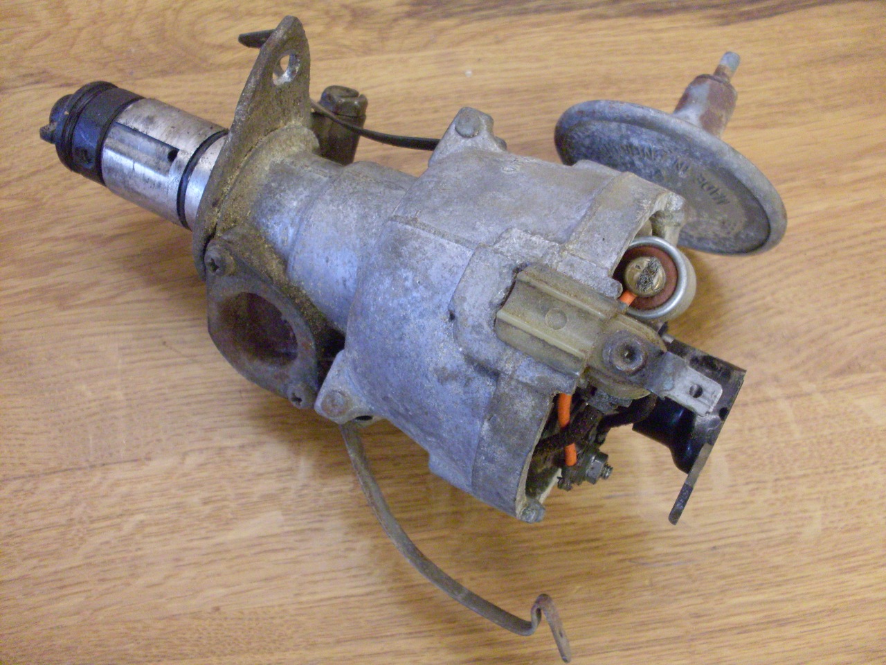
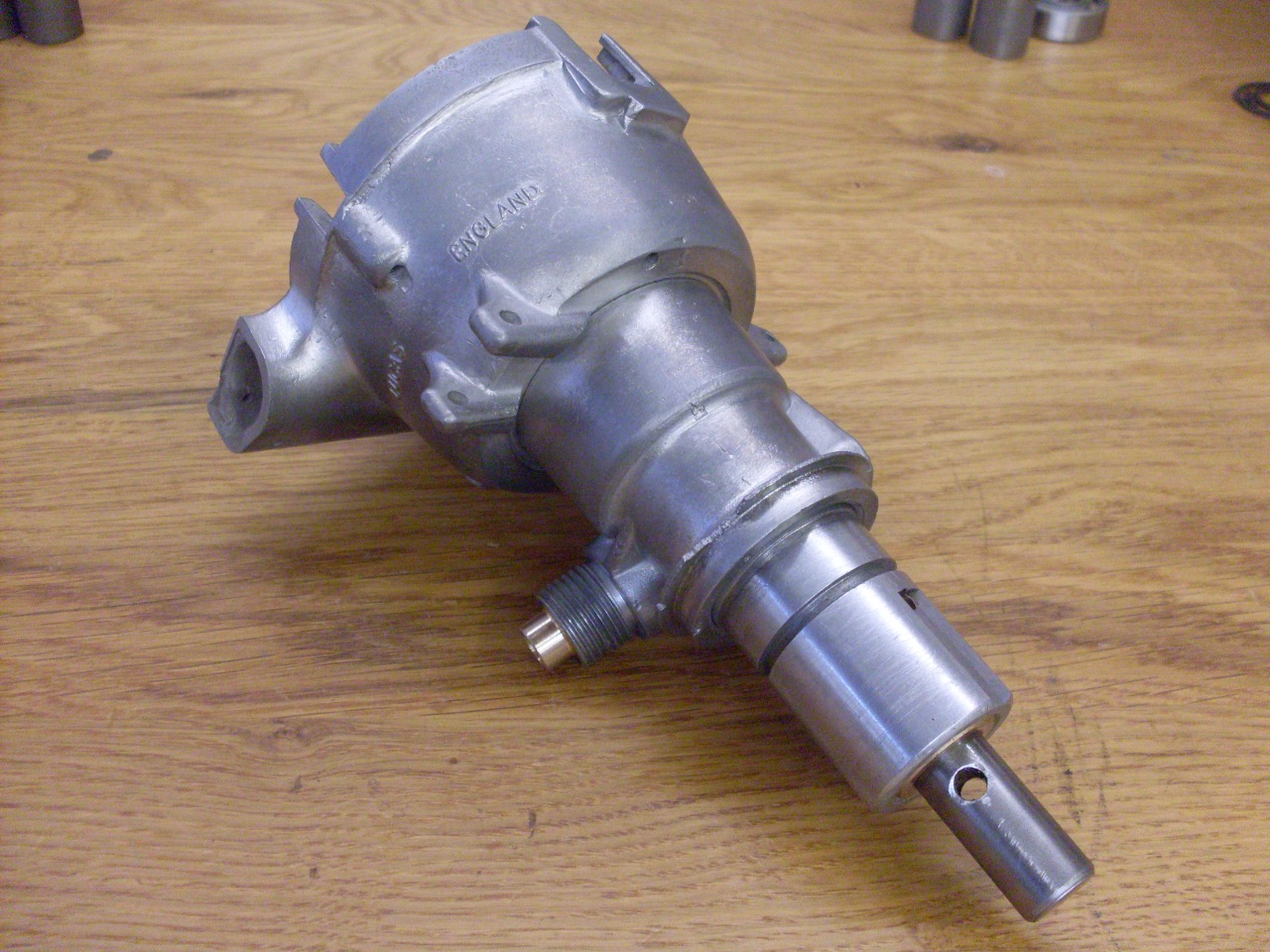
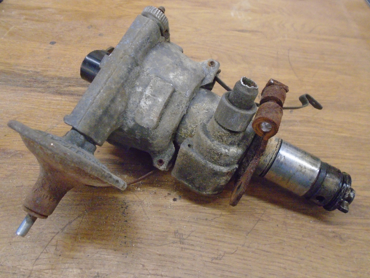
The
distriburtor on my car was the original Lucas 22D type. It is a
pretty ordinary distributor, but has a built-in mechanical tachometer
drive takeoff. Though there is a standard centrifugal advance
arrangement, apparently all of the later model TR6s lacked any
provision for vacuum advance, and some, including mine, only
had vacuum retard capability. The inclusion of vacuum retard
was a consession to US emission laws, and was designed to retard
the ignition at idle to reduce NOX (nitrogen oxides) emissions.
The potential overheating that retarded spark can cause was
handled by a thermostatic valve in the top radiator hose that shut
off the vacuum at higher temps. Since many of the parts for
the vacuum retard and other emissions systems are no linger available,
it can be a challenge to put these systems back in good working order.
One common aproach is to just remove them, so they at least can't
do any harm. This is the approach I'll take with the distributor:
I'll disable the vacuum retard, and consider installing some kind
of vacuum advance.
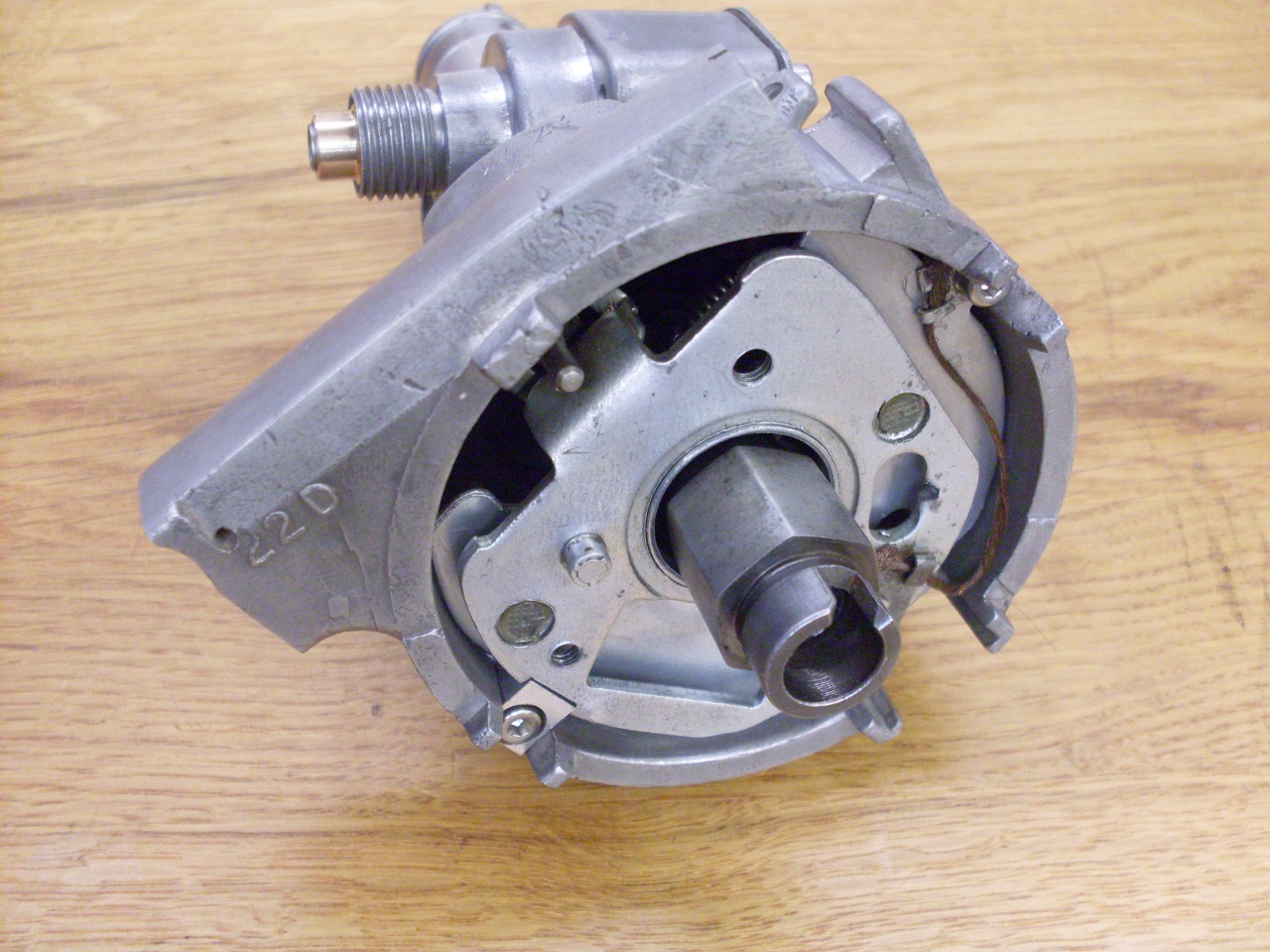
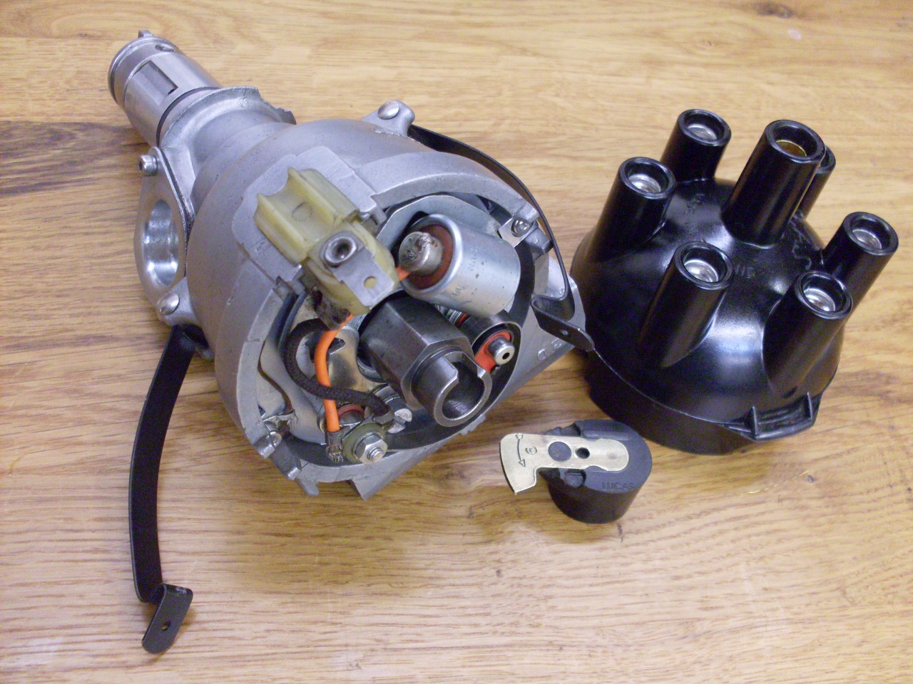
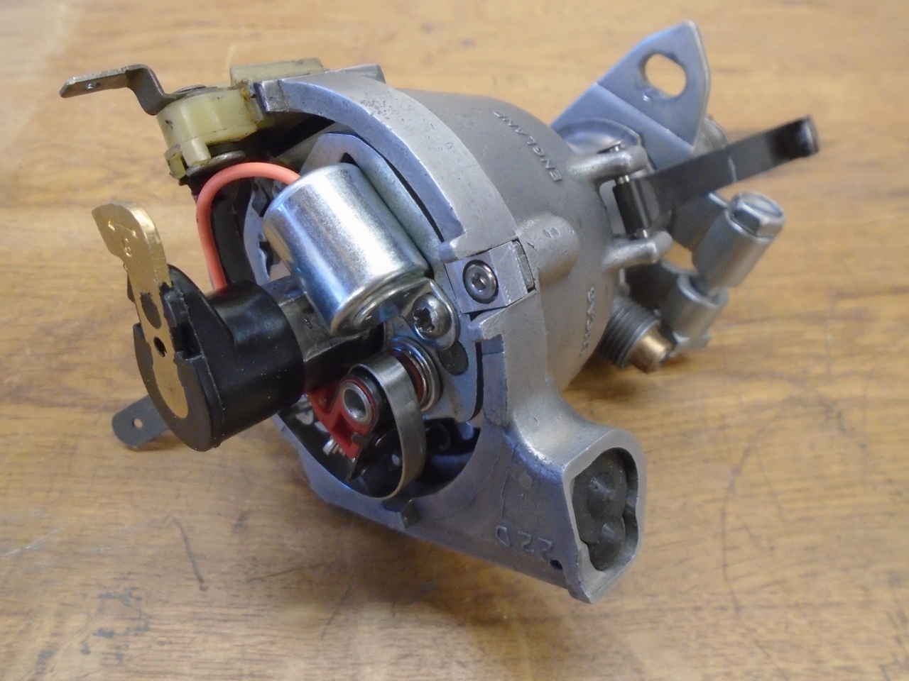
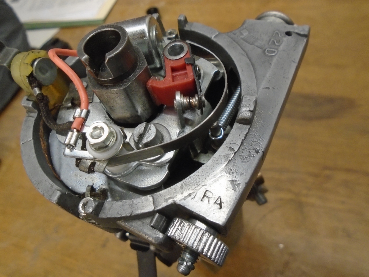
There is quite a bit you can do to this
distributor to bring it back into spec, and maybe even improve it a
little bit. Here is the unit with the cap removed.
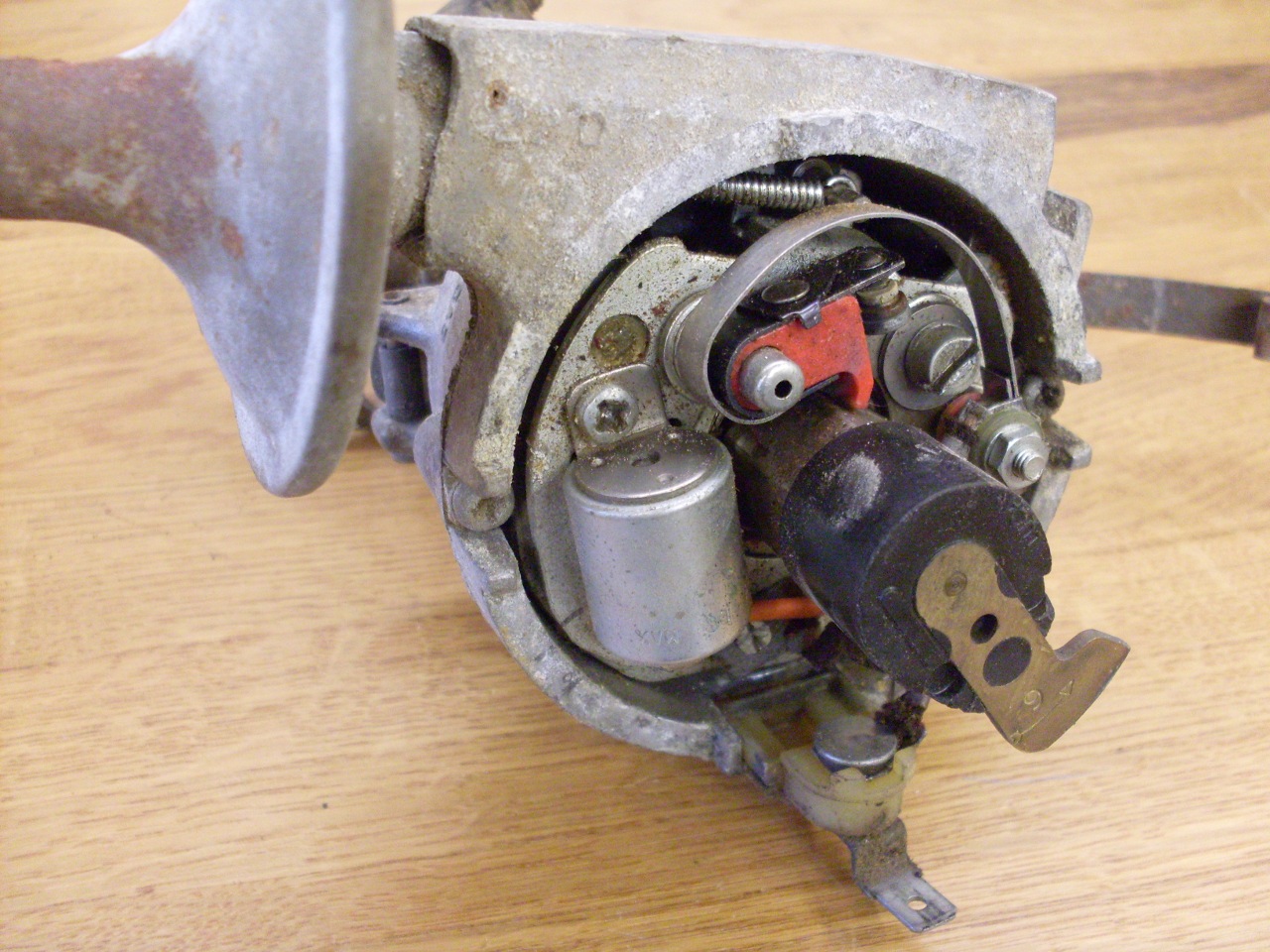
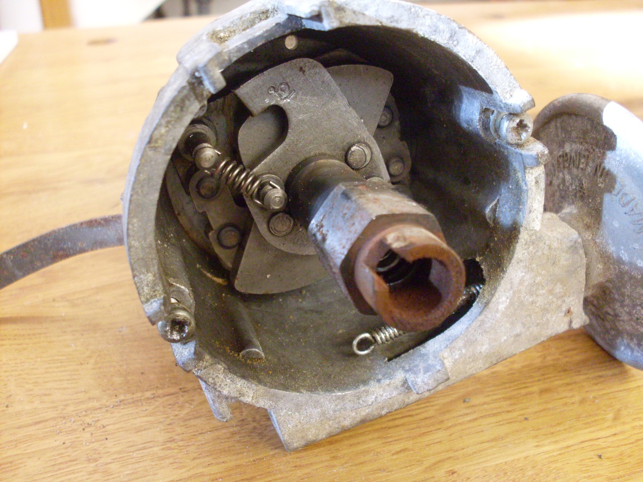
Removing
the rotor, points, and condenser, and then the nested mounting plates
reveals the centrifugal advance mechanism with its weights and springs. The "13°" stamped on the advance cam arm indicates that the maximum centrifugal advance is 13°.
Here is how the tachometer drive is accomplished.
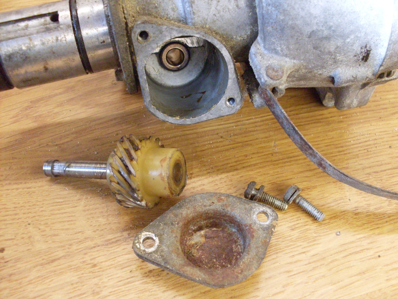
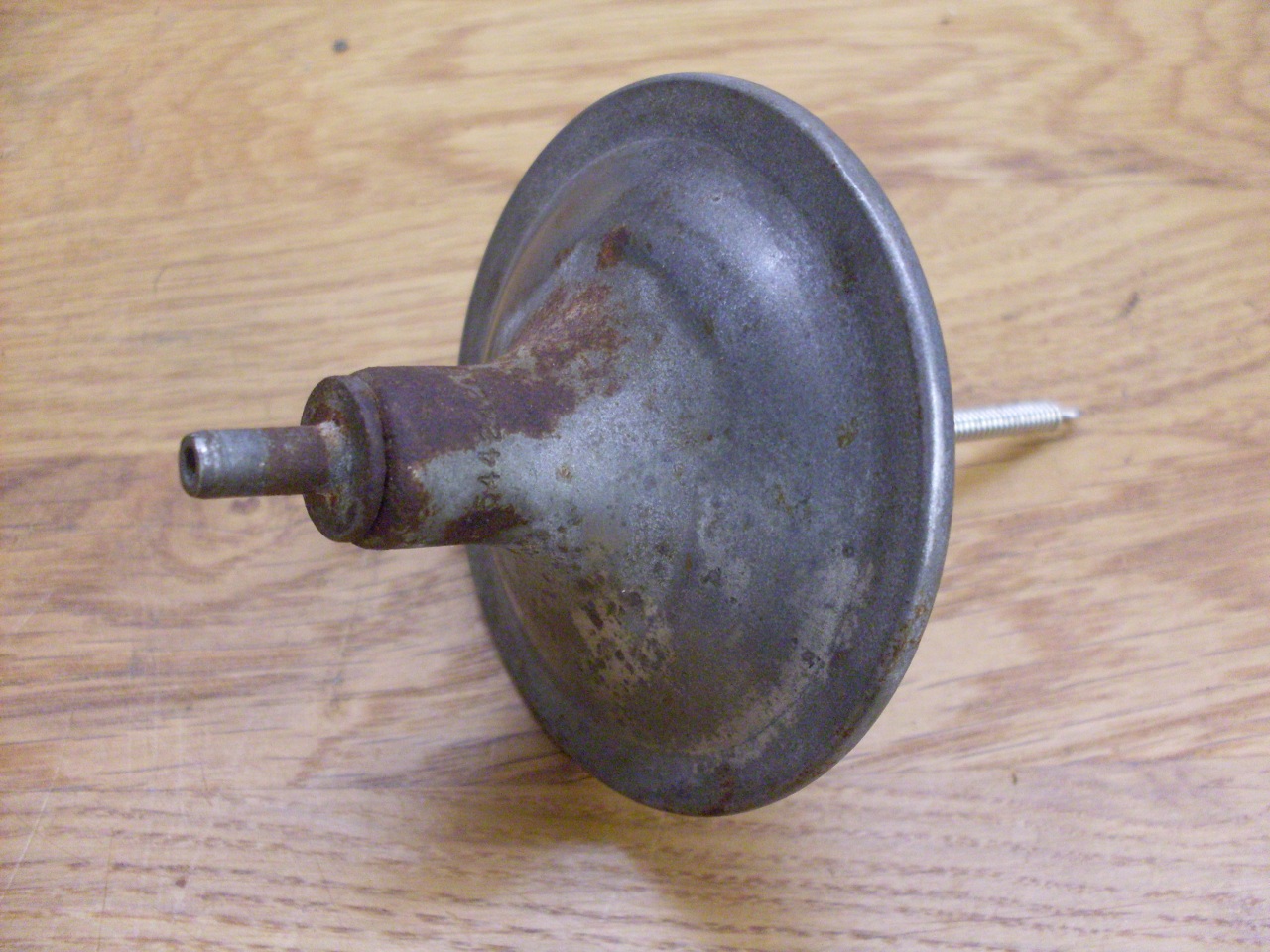
This is the vacuum retard unit. I believe it still works, but I don't want it.
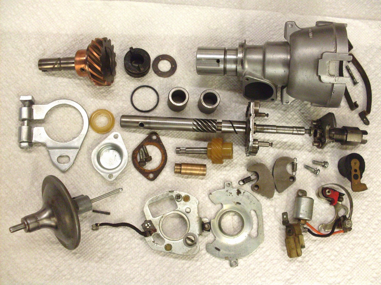
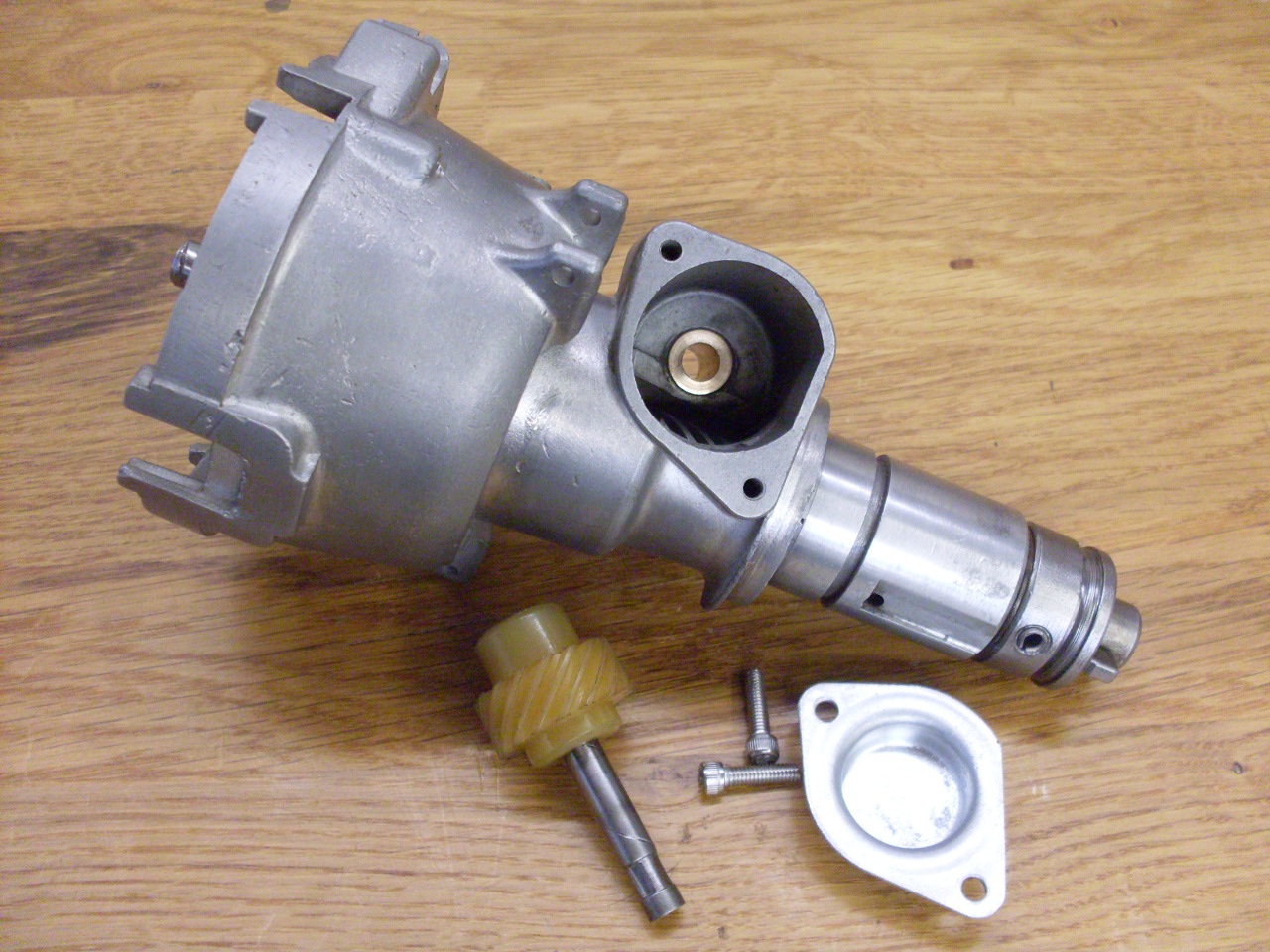
All the parts (some of them have been cleaned up already). Now time to decide what needs attention..
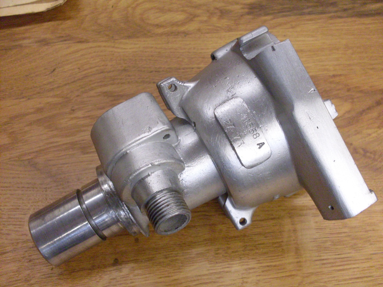
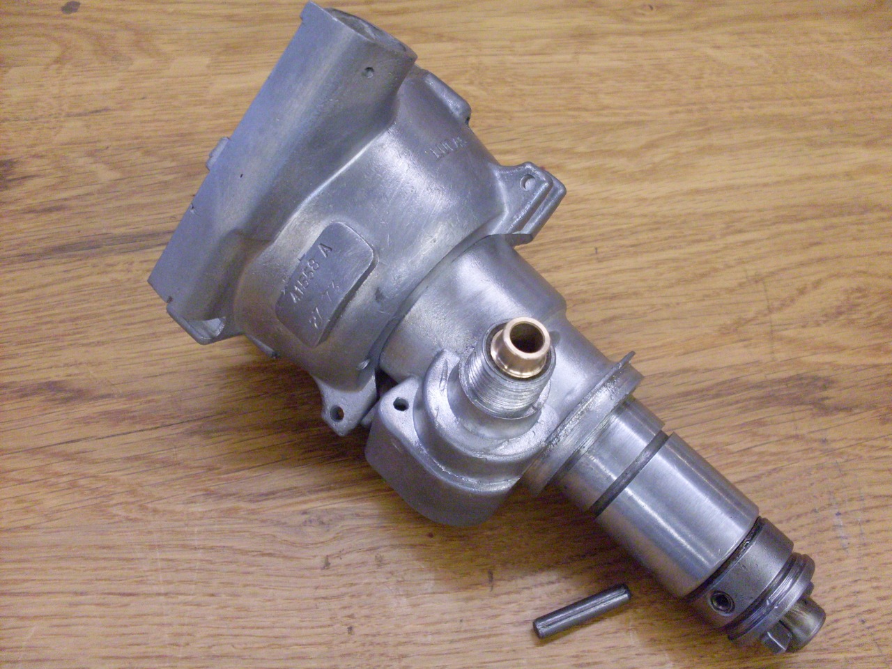
The
body is a roughish Zamak casting, though the part that holds the
spindle bushings appears to be a pressed-in aluminum piece. The
body will clean up OK, and can even be polished to a point, but
the shine won't last long.
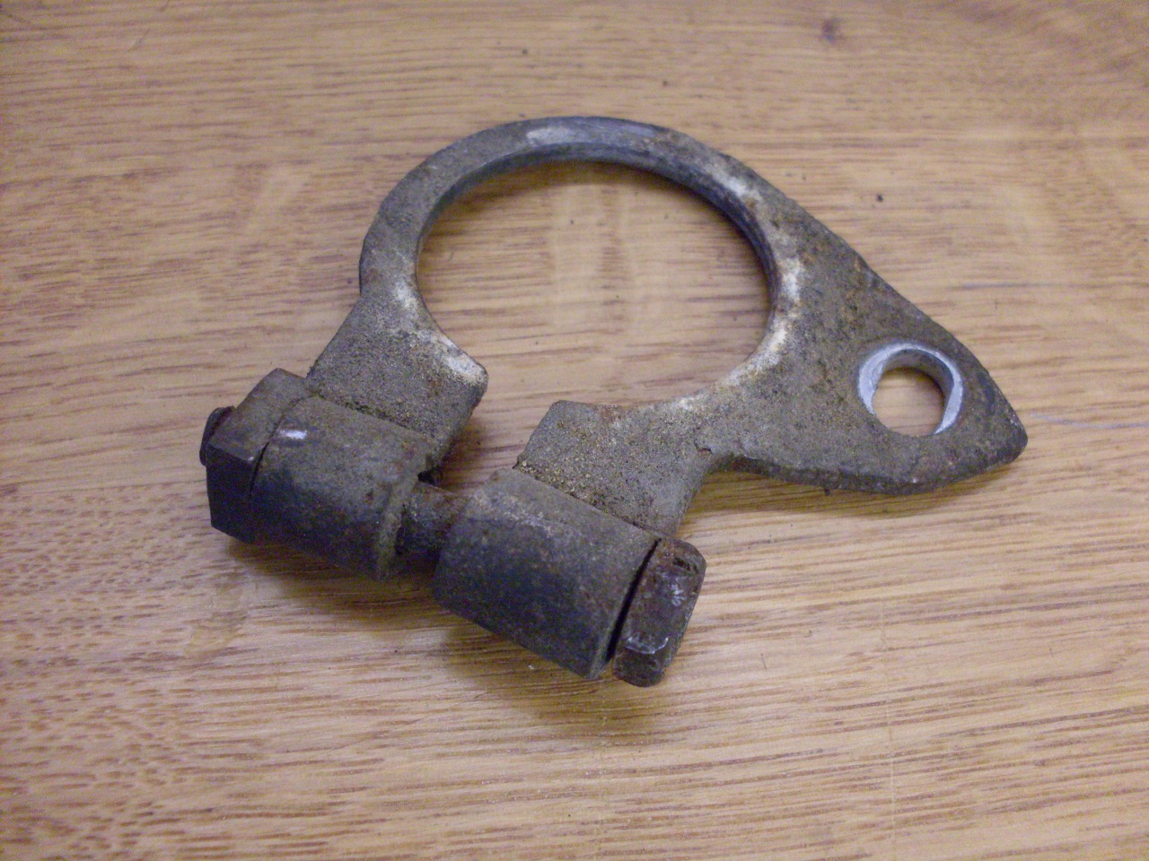
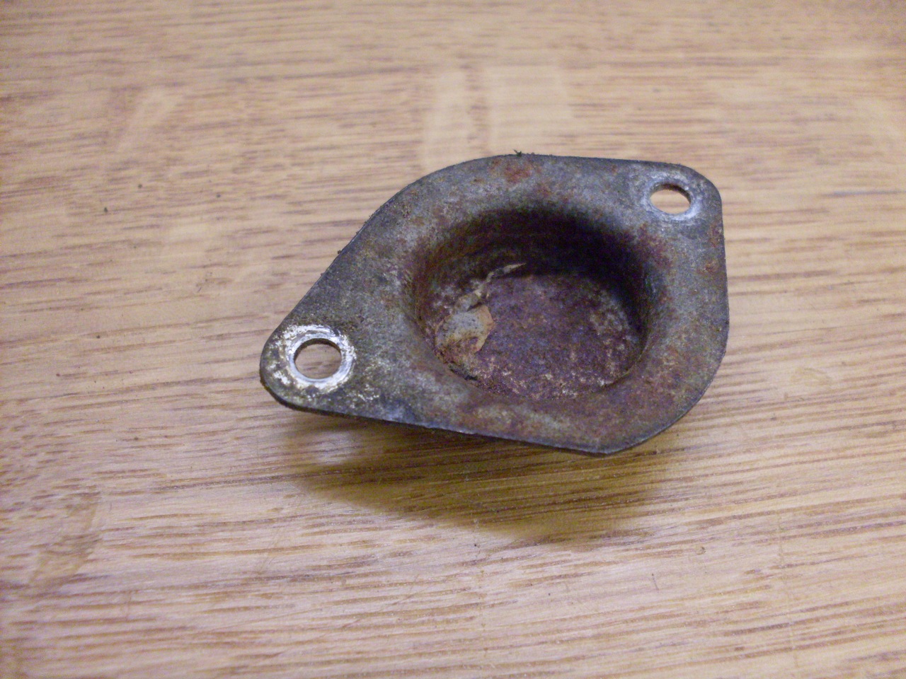
Some of the ferrous parts were pretty rusted. A little reshaping and some new zinc makes them much prettier..

I got the tach drive bush from an industrial supplier, but it had to be modified a little.
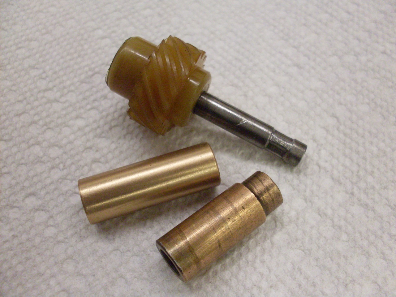
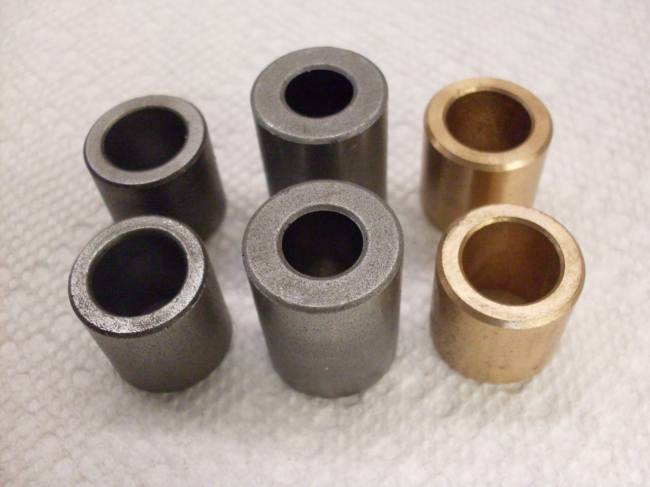
The
main spindle bushings felt a little loose to me, so I pulled them out.
They were iron-based Oilite bushings called "Super Oilite".
Super Oilite bushes are harder than regular bronze oilite bushes,
but I'm not sure why they were specified for this application--it
doesn't seem that demanding. Without any copper, Super Oilites
can be cheaper--that might be the reason. The main spindle is a
bit of an odd size--about 0.490" in diameter, and I couldn't find
standard items to fit. I did manage to get a couple from a
well known distributor rebuilder, but they came as bronze Oilite.
In parallel, I ordered some Super Oilites with the right OD, but
smaller ID that would have to be machined to fit the shaft.
Machining Oilite can be tricky--any dullness in the tool can
"smear" the material, closing up the lubrication pores.
Manufacturers recommend very sharp tools to machine the wear
surfaces.
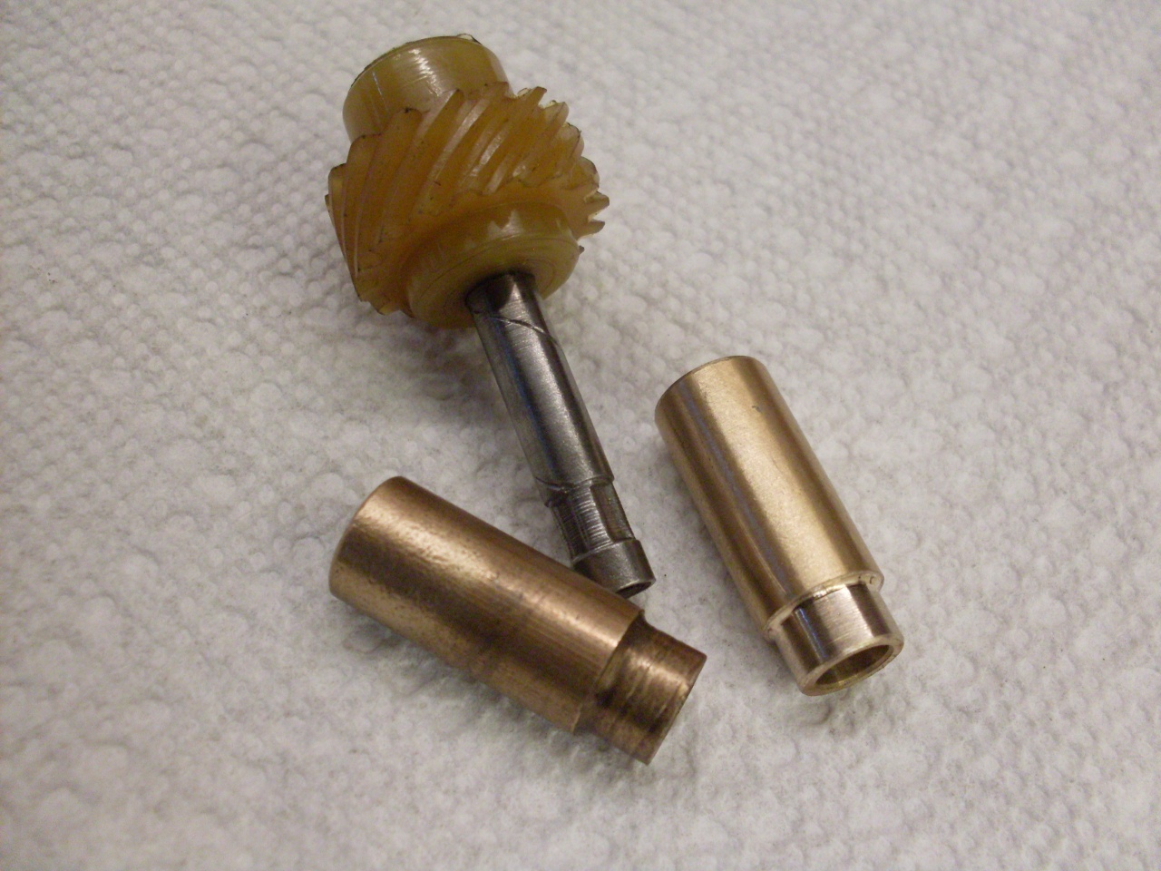
In
the end, I decided to use the bronze Oilites. The loose bushes
were a nice fit on the spindle, but after pressing them into the
body, the spindle fit was pretty tight. This wasn't unexpected,
since Oilite can't resist compression forces very well, so I
reamed them to very slightly larger than the spindle. This of
course has to be done so that the bores in the two bushes are colinear.
Installed the tach drive bush also. Its fit wasn't as tight
as the spindle bushings, so it didn't need reaming.
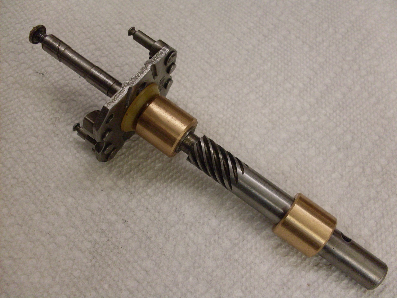
The
spindle was a very nice fit in the new bushings. Lubed with oil,
it has silky smooth rotation with no detectible play. I put on
the drive dog and thrust washer using spring roll pin instead of the
original dowel.
Next
was the tach drive gear and cover. I can't seem to remember to
order gaskets in time for assembly, so I made the one under the gear
cover from 1/32" gasket material. The gear was lubed with a moly fortified lithium grease. I replaced the bunged up
original 4BA phillips screws with stainless socket head types.

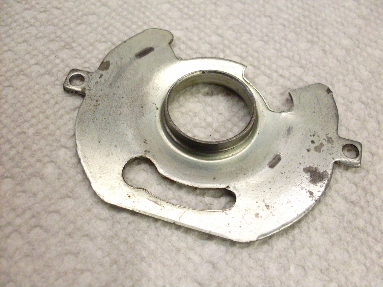
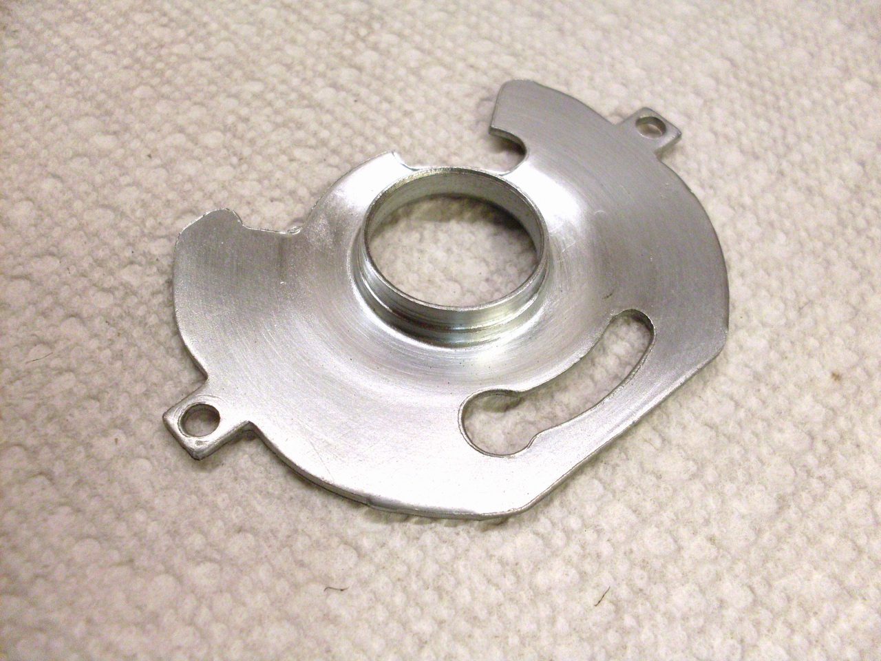
Moving
back up to the business end of the distributor, the backing plate was
servicable, but stained, so I gave it a quick zinc re-plate.
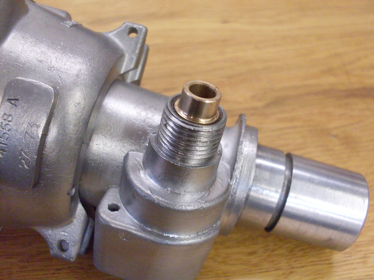
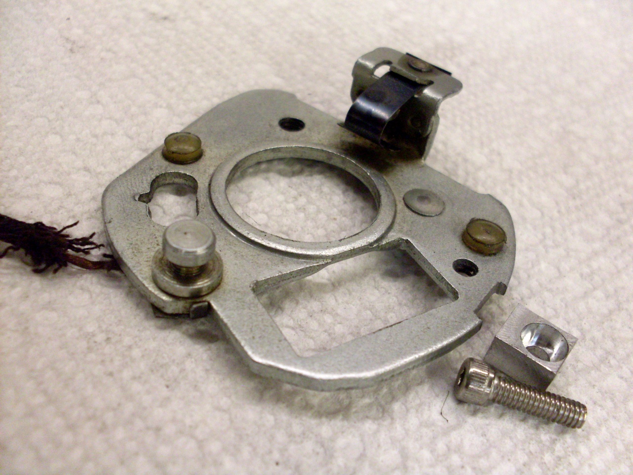
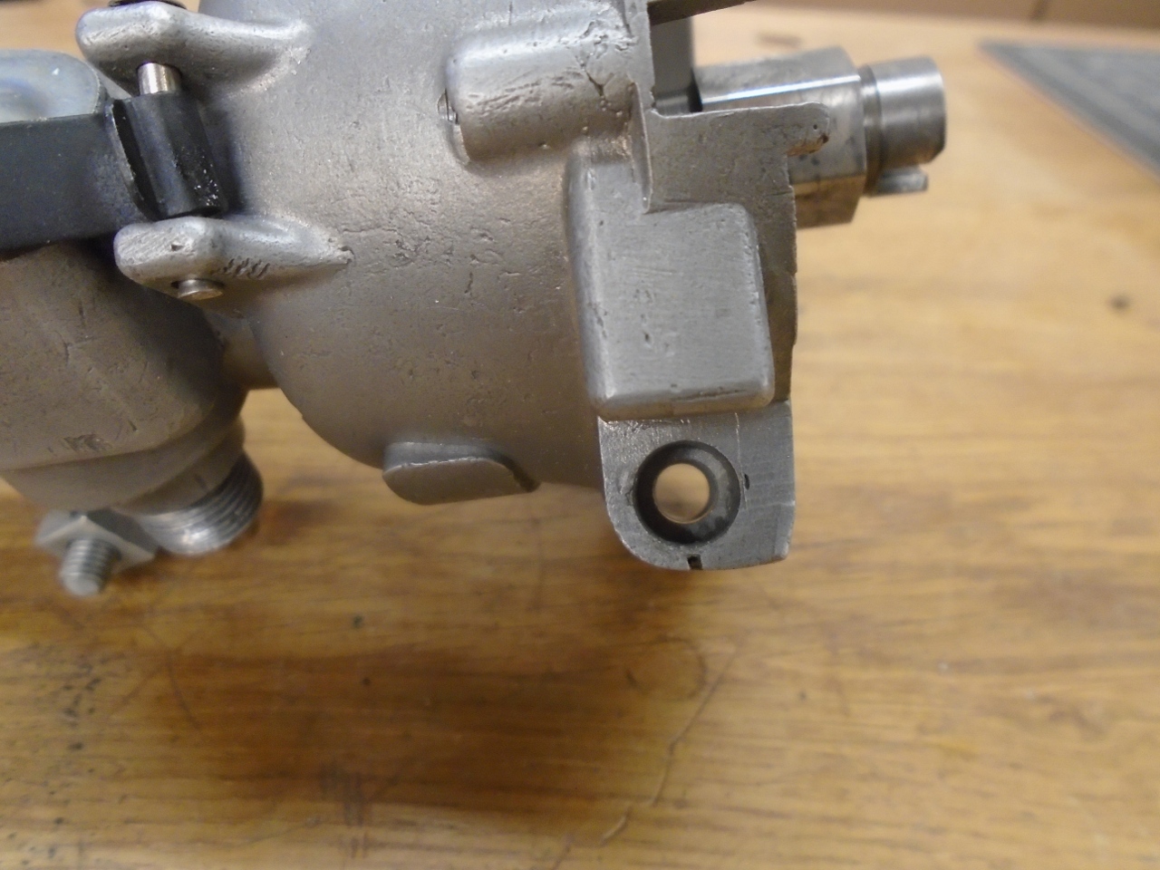
Since
I intend to disable the vacuum retard on the distributor, I decided to
do away with the retard capsule all together and not even install it.
One consequence of this is that there is then nothing to
positively locate the bearing plate, which holds the points.
Normally, the retard (or advance) capsule locates the bearing
plate based on the vacuum it sees. With no capsule, the bearing
plate would be free to rotate on the base plate, which could
drastically affect timing. My solution to this needed to be
easily reversible since I want the option to install a vacuum advance
capsule later. The route I chose was to install a little key
fixed to the body which would mate with a notch filed into the bearing
plate.

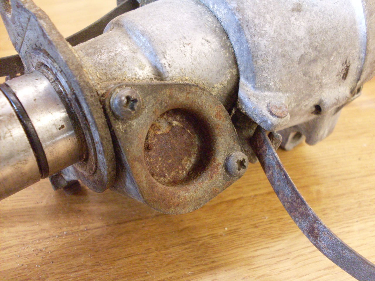
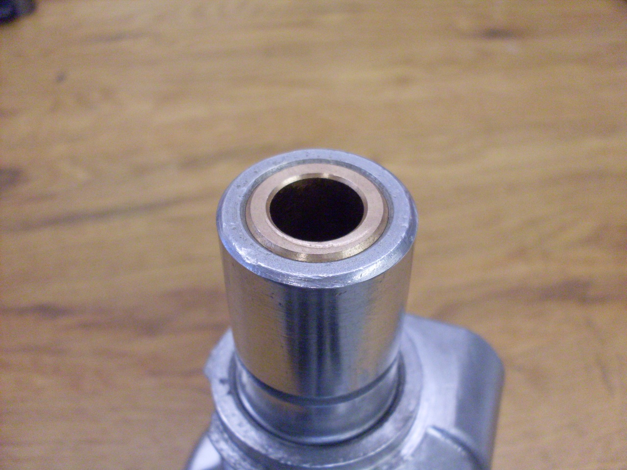
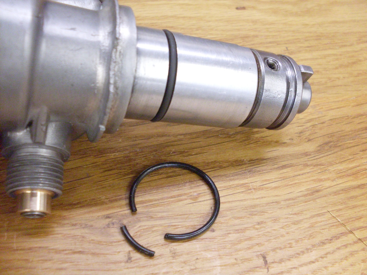
Back
at the bottom end, there is an O ring that keeps the oil on its way to
the spindle bushings from escaping. The old O ring was totally
cooked. It was hard and brittle, and broke when I removed
it. I don't know what material was specified for this O
ring, but whatever it was, it wasn't up to the job. I got an -021 hi-temp Viton ring to replace it.
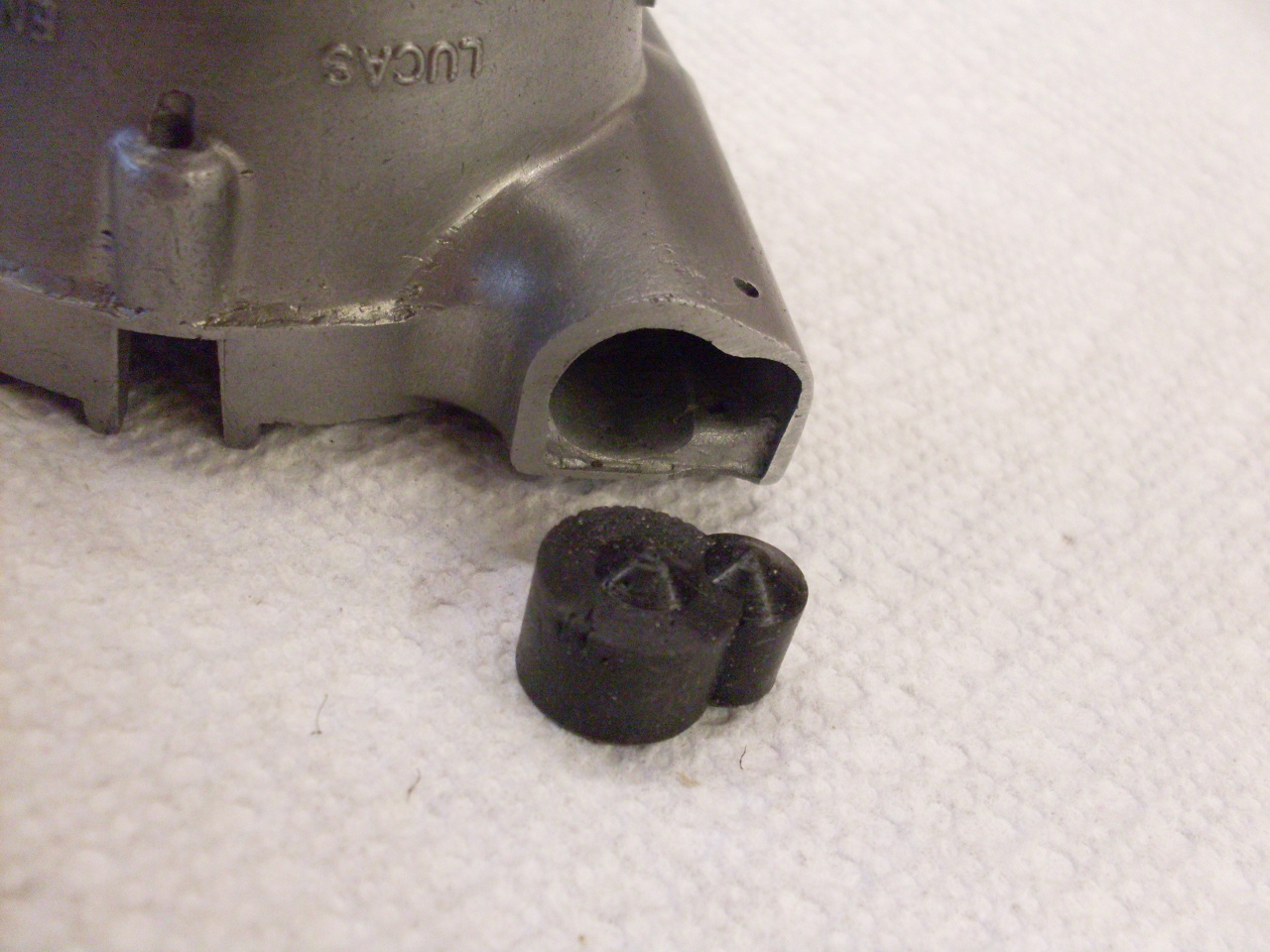
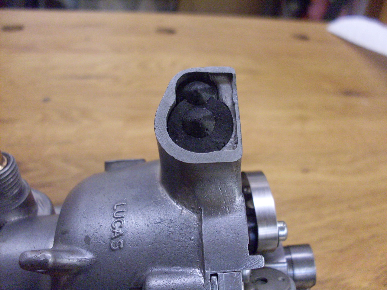
One
final afterthought was the gaping opening left by the eliminated vacuum
capsule. Now this distriburtor is by no means air tight, but
leaving this gap just seemed to invite trouble. I took some
time to cast a little plug for the hole. It's a snug fit,
but I'll still retain it with the original pin from the capsule. This way, I won't lose the pin.
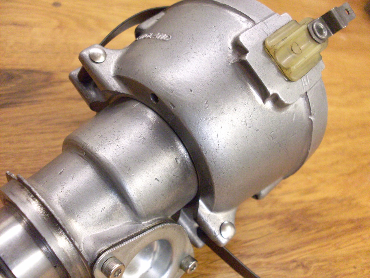
New
stainless rivets for the cap clips, and we have a distributor!
That's the old points and rotor--I'll replace those when the time
comes.

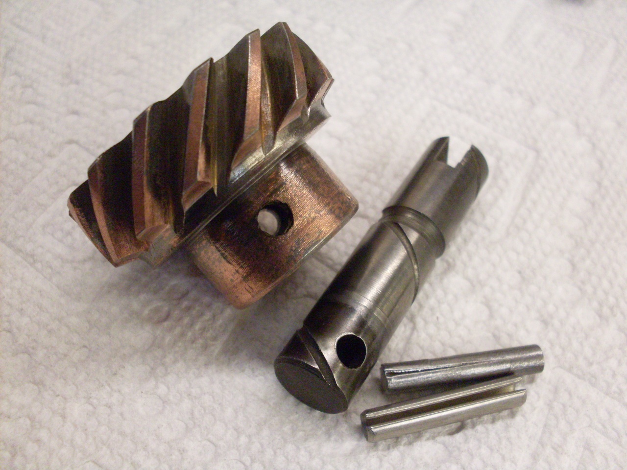
Even
though not really part of the distributor, I looked at the distributor
(and oil pump) drive gear. One thing I noticed when cleaning it
up was that it was a little loose on its shaft. More than a
little,
actually--the gear could be moved well over 2 degrees on the
shaft. My first thought was that this could affect timing.
There is at least one outfit on the internet that offers to fix
this common problem for you for 30 or 40 dollars to cure "jumpy"
timing. After some more thought, I realized that since the
distributor is keyed directly to the gear and not to the shaft, this
couldn't directly affect timing. I wonder how many people go for
the "fix".
On the other hand, I don't like things loose, so I fixed it. The gear is pinned to the shaft, and the original used
a grooved dowel pin (I believe it may be called a "Mills pin" in
England). A grooved dowel pin is a straight pin that is distorted
(on one end in this case) by forcing a groove into the pin. This
upsets the metal, and expands the diameter a little in the grooved
area. The problem is apparently that when the pin is driven home,
the distorted part is a tight fit in the gear, but a little loose in
the shaft hole. I don't know how the commercial places fix these,
but I used a Slotted Spring Pin--called a Roll Pin sometimes. In
it's relaxed state, it is a little larger than the hole it is designed
for. When it is driven into the hole, it compresses a little.
When it is in final place, each part of the pin will try to
expand into the hole it is in. The Spring Pin removed all traces
of looseness in the gear--for about 15 cents and 15 minutes' time.

Update--March 14, 2019
Well,
it's now a little over 5 years later, and the car is essentially
finished. It's been started, licensed, and insured, but I'm
waiting for decent weather for a first outing. There is still a
list of little things to do, and one of them is to add a "micro
adjuster" to the distributor. The micro adjuster provides a
little thumb wheel that can be used to fine tune the ignition timing
without loosening and turning the entire distributor.
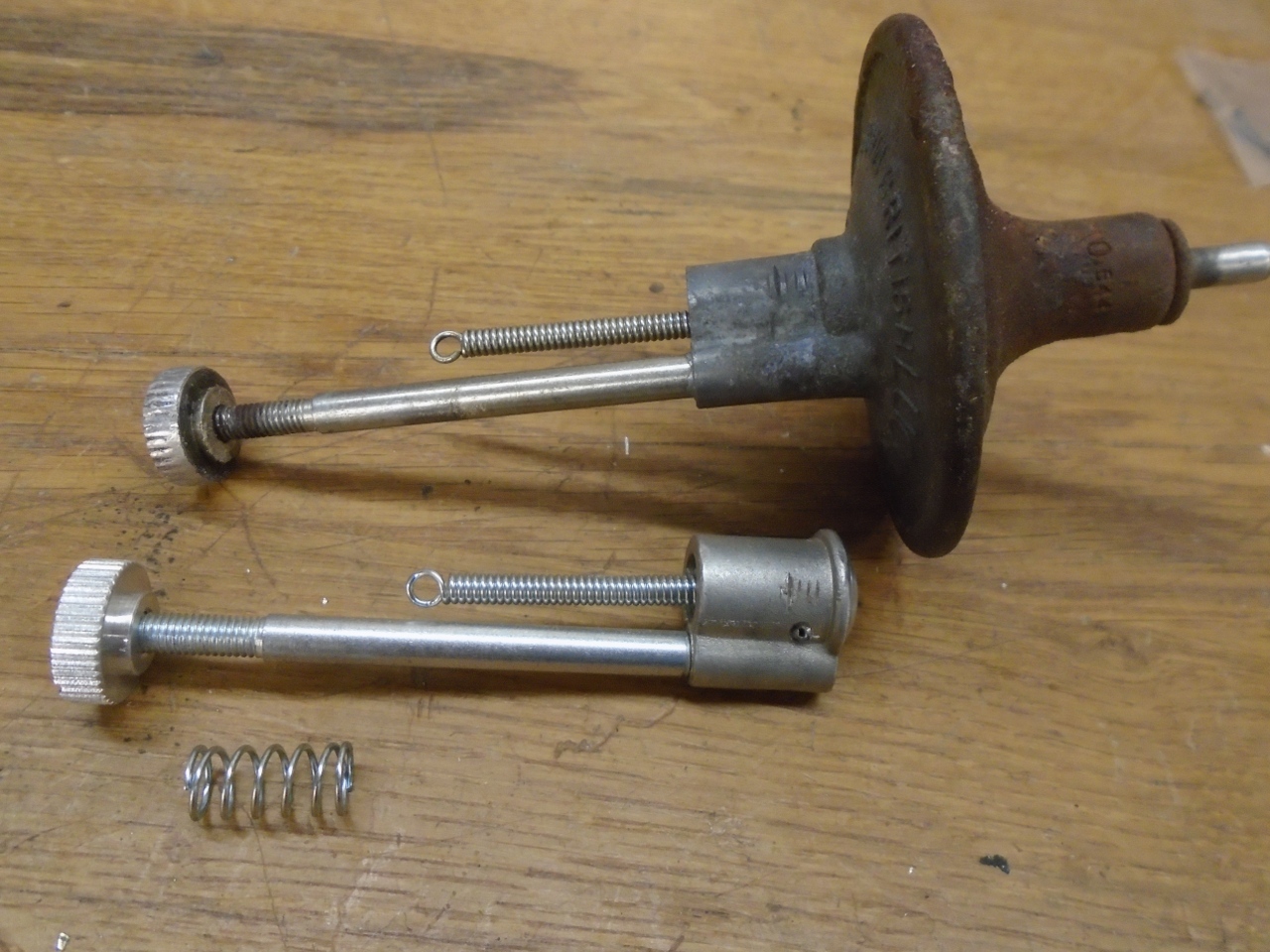
Micro
adjusters were pretty common on British cars of the day--both my MGA
and GT6 have them, but the TR6 did not, though it appeared that the TR6
distributor body was set up for it. I think all of the adjusters
I've seen were used in conjunction with vacuum advance capsules, but
since I'd decided to not add vacuum advance to the TR, I needed just
the adjuster without the capsule. I found just such a unit from a
Jaguar supplier. I don't know if these were ever used on a
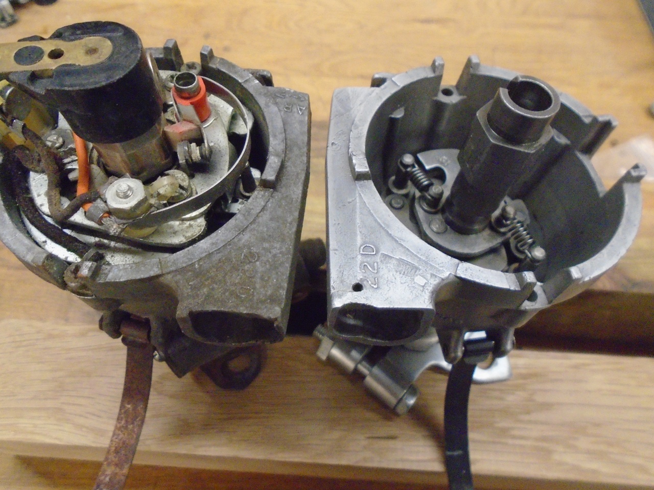
production car, or if it is a specialty item. The right picture
shows how it compares to the typical vacuum advance unit.
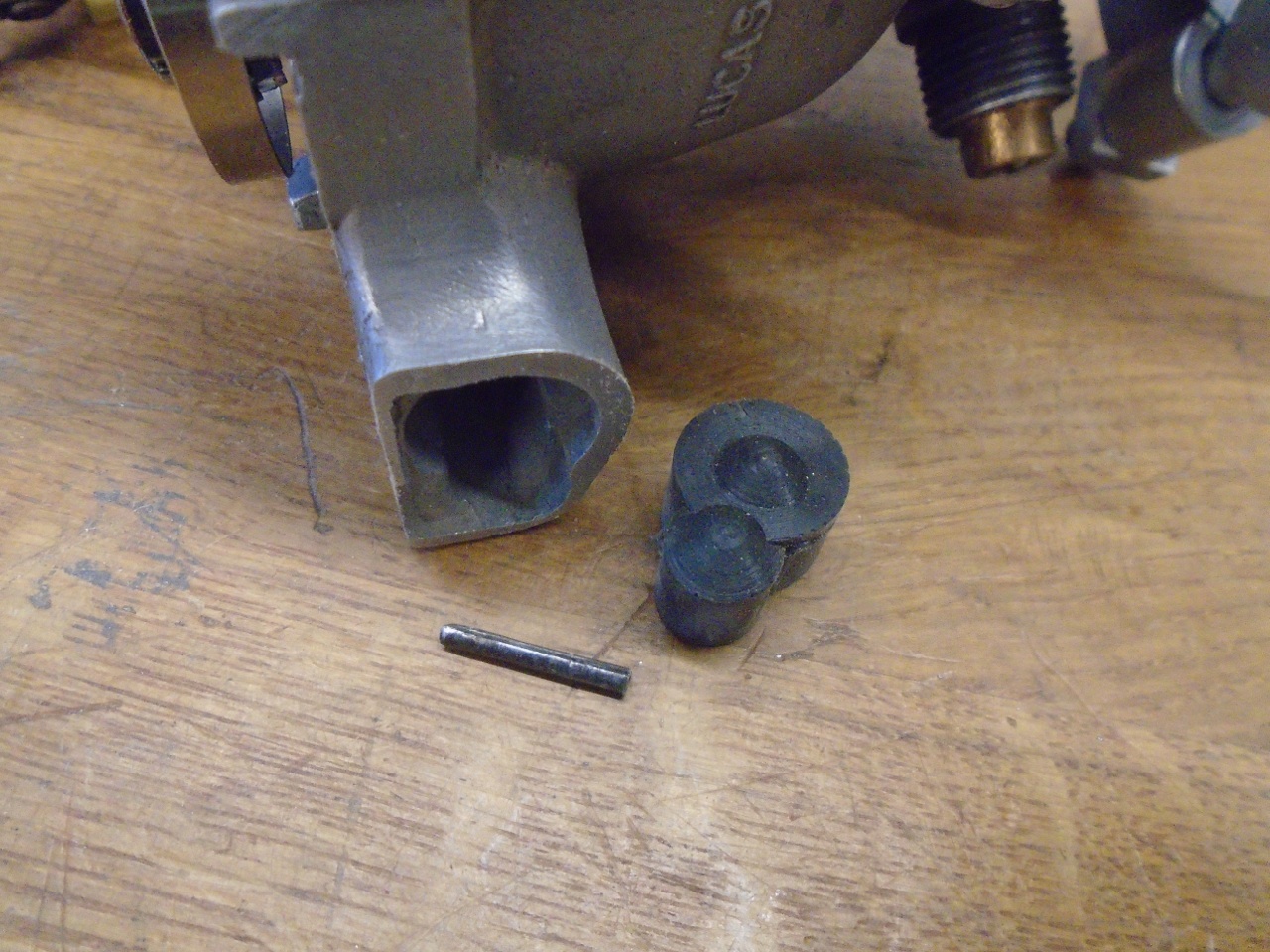
For
install, I first had to undo the things I did when I ditched the stock
vacuum retard unit. The little locking block and the rubber plug
were removed.
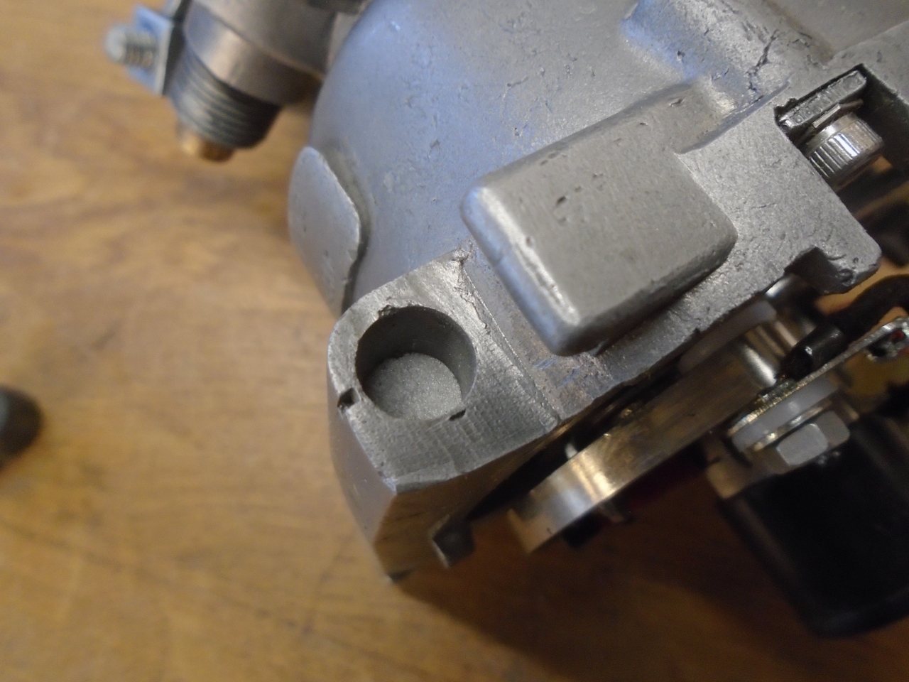
When I went to slide the adjuster in place, I hit a snag--the hole for the adjuster shaft was blanked off.
Now,
drilling a hole for the shaft would normally be a trivial thing, but
since the thumbwheel has a little detent spring that it has to bear
against, it seemed like the position of the wheel was fairly critical.
Shoud the hole be oversized, or should it be a snug fit on the
shaft to positively locate it? Also, the exact direction of the
hole wasn't obvious since the distributor body in that area didn't have
parallel surfaces. To answer these questions, I opened up the
sleeping GT6 and yanked its disributor.
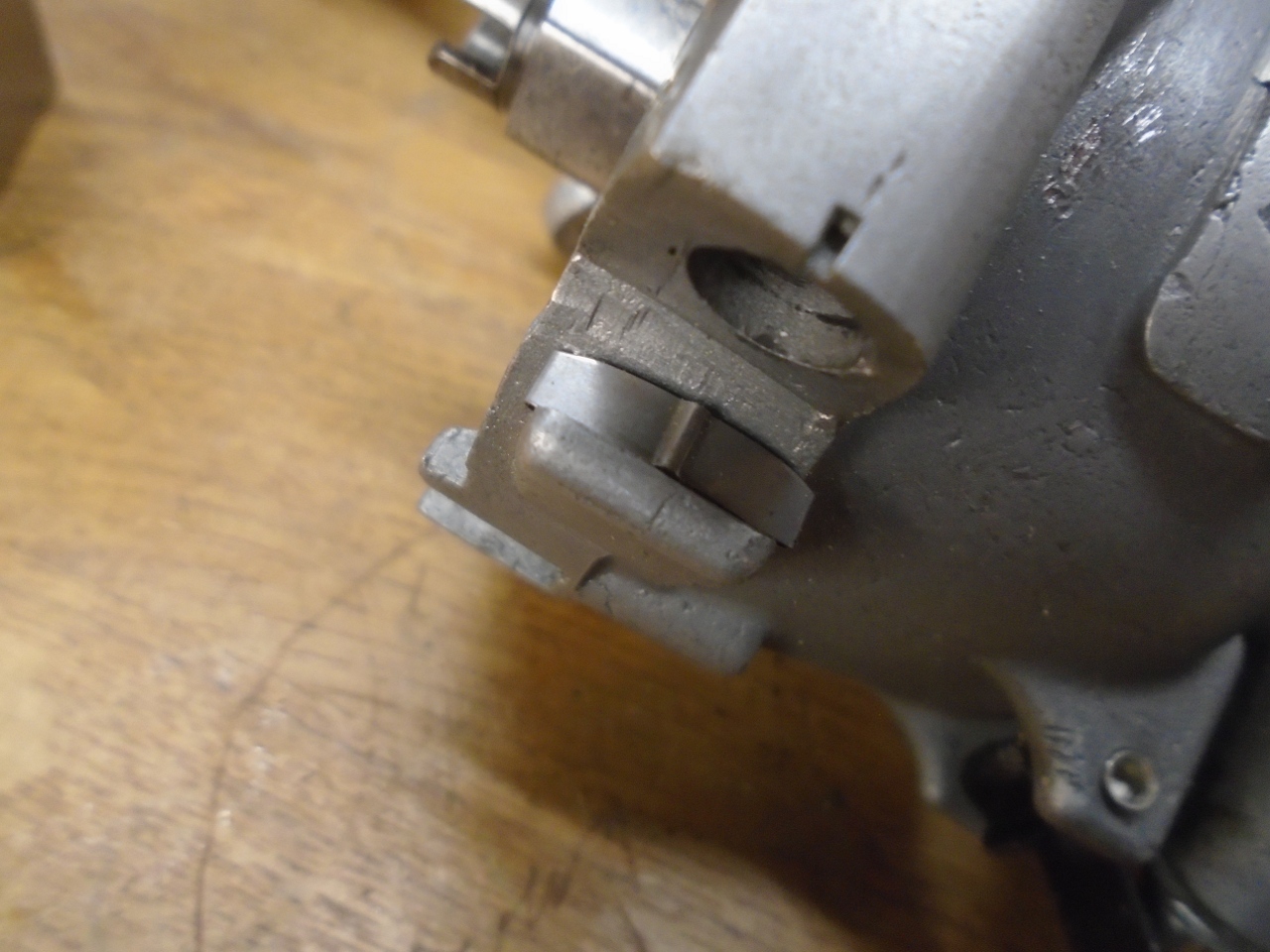
I
put in a hole the same size and direction as on the GT unit. The
hardest part was finding some way to solidly hole thd distributor for
drilling.
I
had a "Duh!" moment when I looked at the TR and GT distributors side by
side. One is a mirror image of the other. Obviously, I
finally realized, this is because the GT had vavcuun advance, while the
TR had vacuum retard.
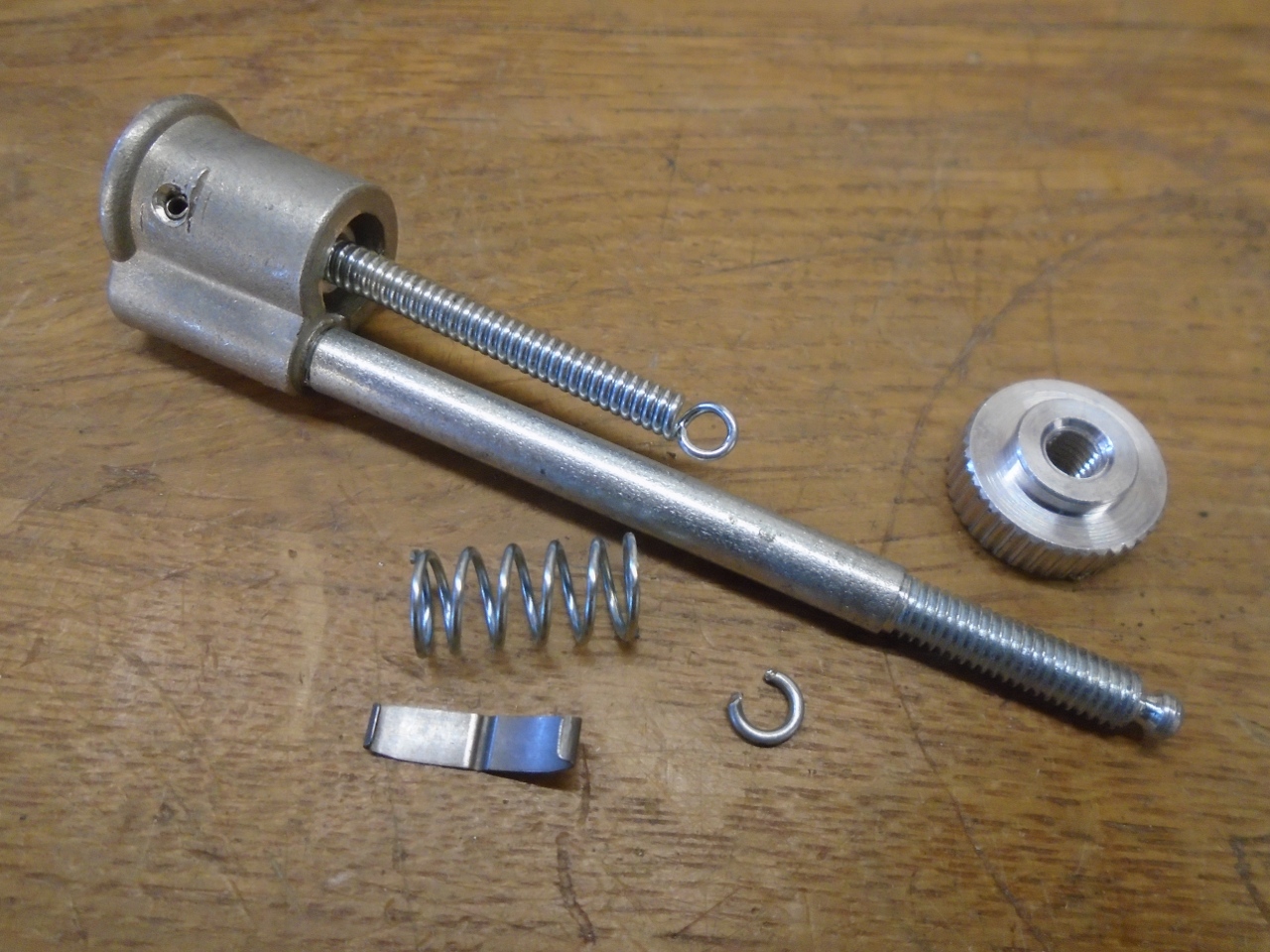
The
litttle detent spring went in. The coil spring, not found on the
GT advance unit, makes sure that any backlash in the adjuster is always
biased in one direction
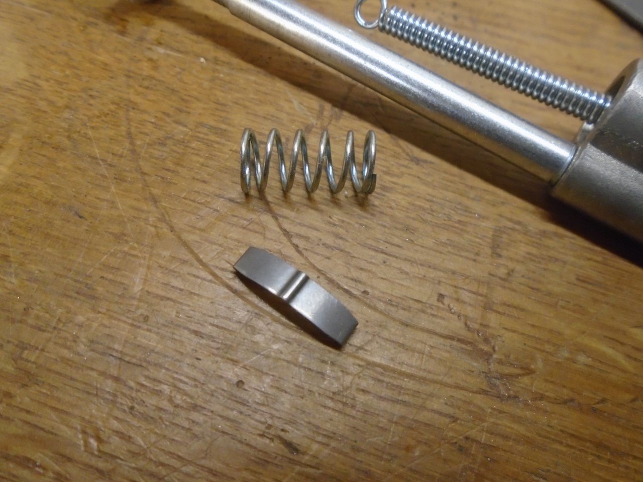
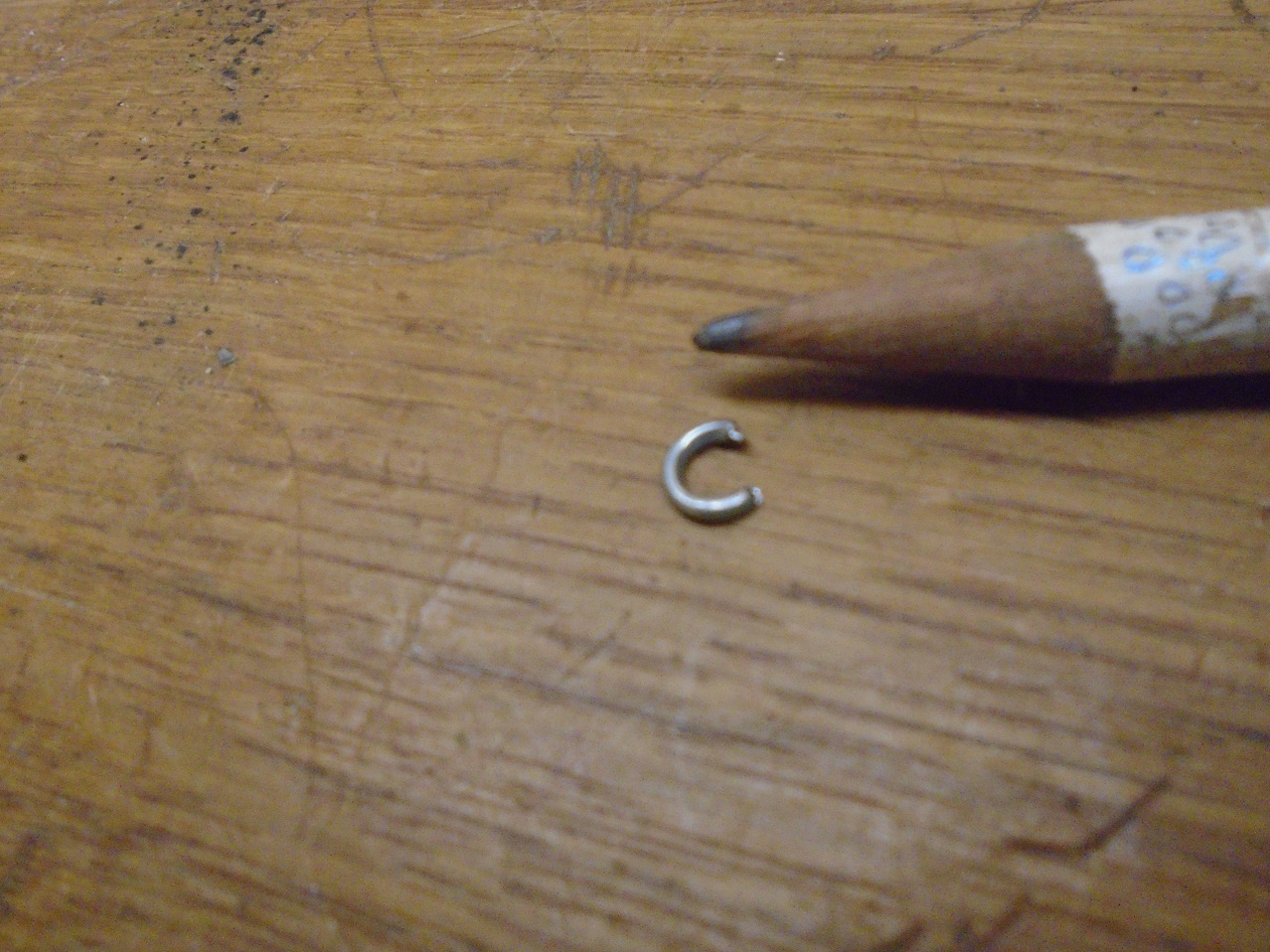
Then this little keeper goes on the end of the shaft so the thumbwheel can't be turned too far.
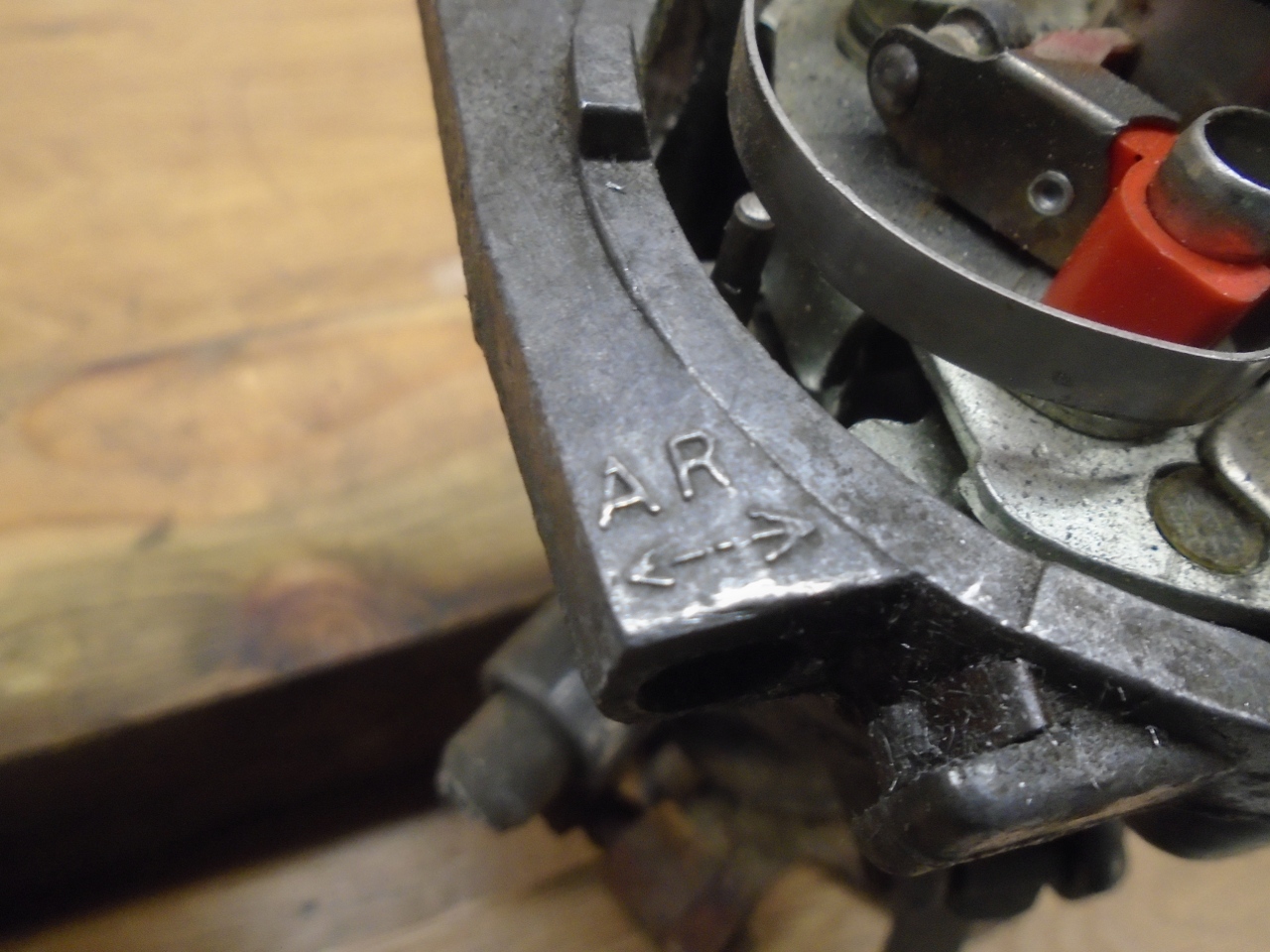
The
GT Distributor had markings showing which way to turn the wheel to
advance or retard. I was pretty proud that I realized in time
that the marking would have to be reversed for the TR.
The
micro-adjuster has about eight turns from stop to stop. Since the
thread pitch is 32 TPI, the total travel is right at 1/4 inch.
This translates to about 13 degrees of timing range. If I
set the adjuster in the middle of its travel, then set the distributor
static timing to 10 degrees BTDC, I'll have around six and a half
degrees of advance or retard to play with. A full turn of the
thumbwheel should be about 1.6 degrees, and for the OCD crowd, one
click of the detent spring is 0.045 degrees.
To my other TR6 pages.
Send comments to: elhollin1@yahoo.com