To my other MGA pages
June 7, 2025
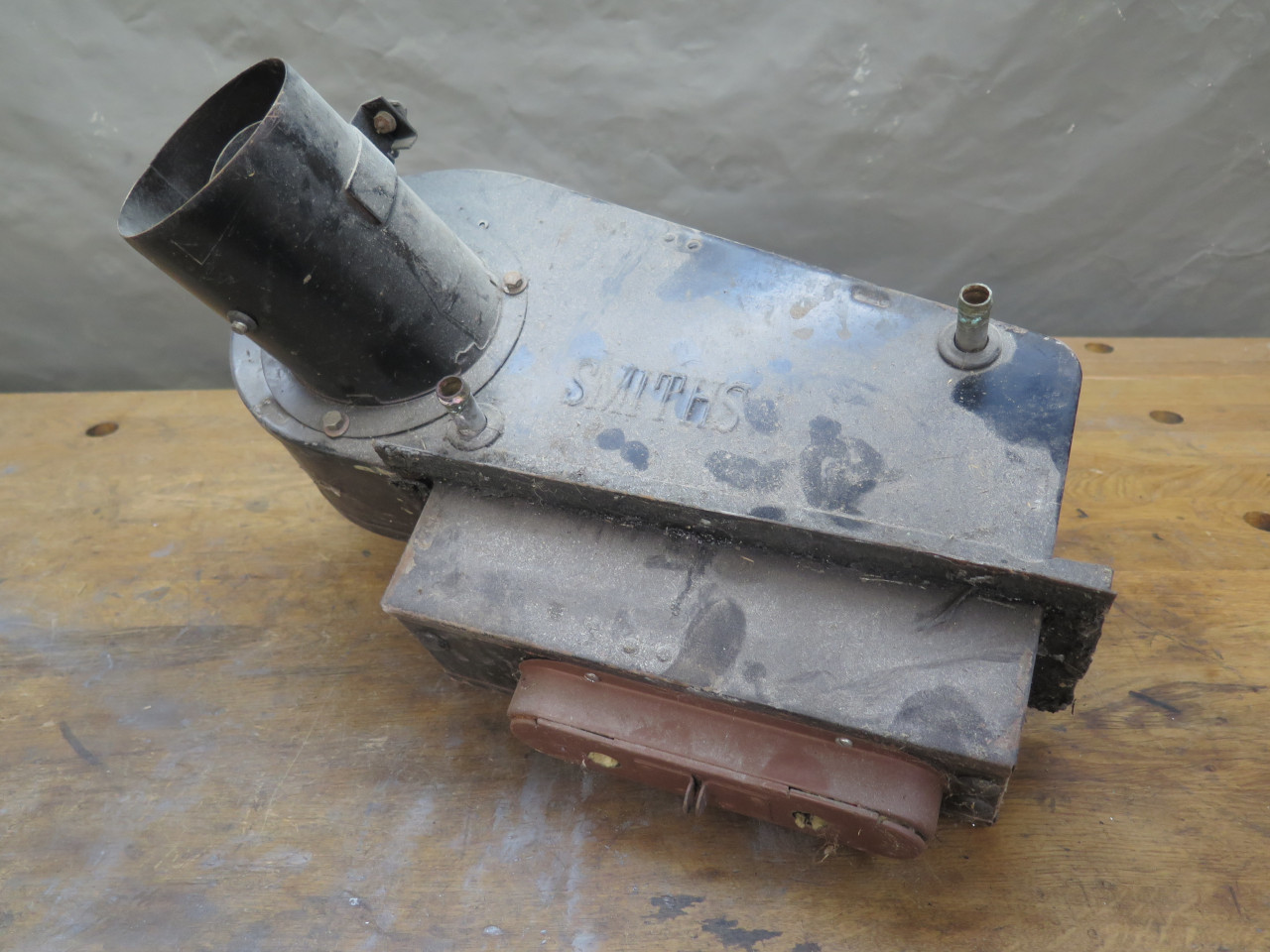
Heater
The cabin heater was actually an optional accessory on MGA cars, but in many markets, it was essentially standard.
It is of a pretty standard design consisting of a radiator core fed from
the engine cooling system, and a blower motor driving a squirrel cage
fan. Unlike many cars of the day and since, it lived in the engine
compartment, and not behind the dashboard.
To jump ahead to the blower motor, where most of the drama was, click here--> Blower Motor.
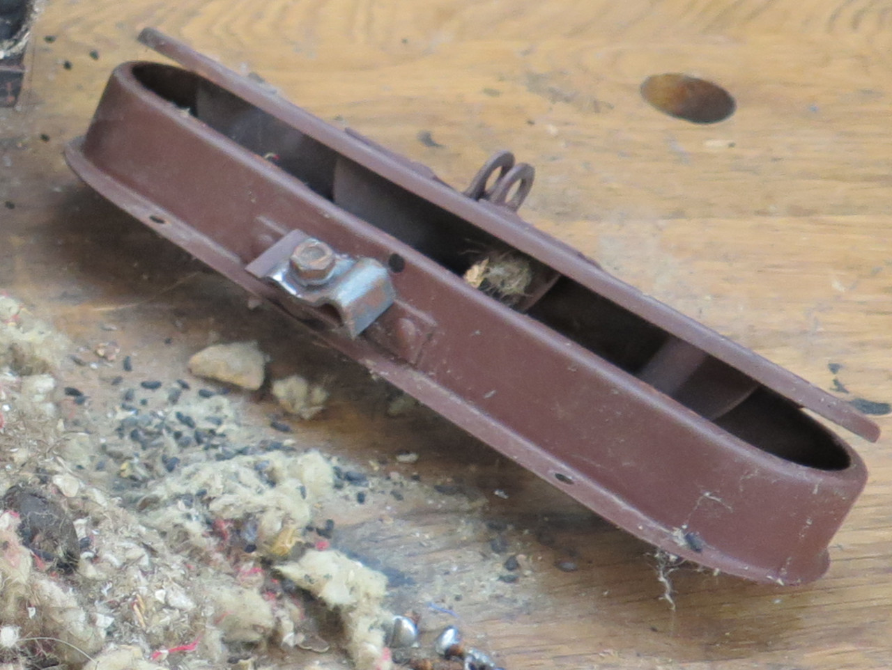
I had painted the heater unit back in my 70s restoration, so it was now dirty, but not all that bad in appearance.

It had apparently been serving as living quarters for generations of small rodents though.
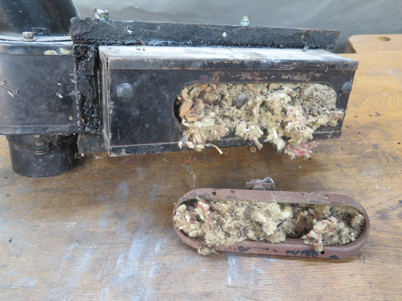
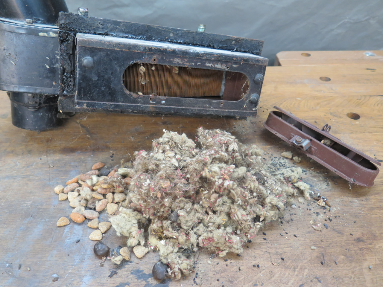
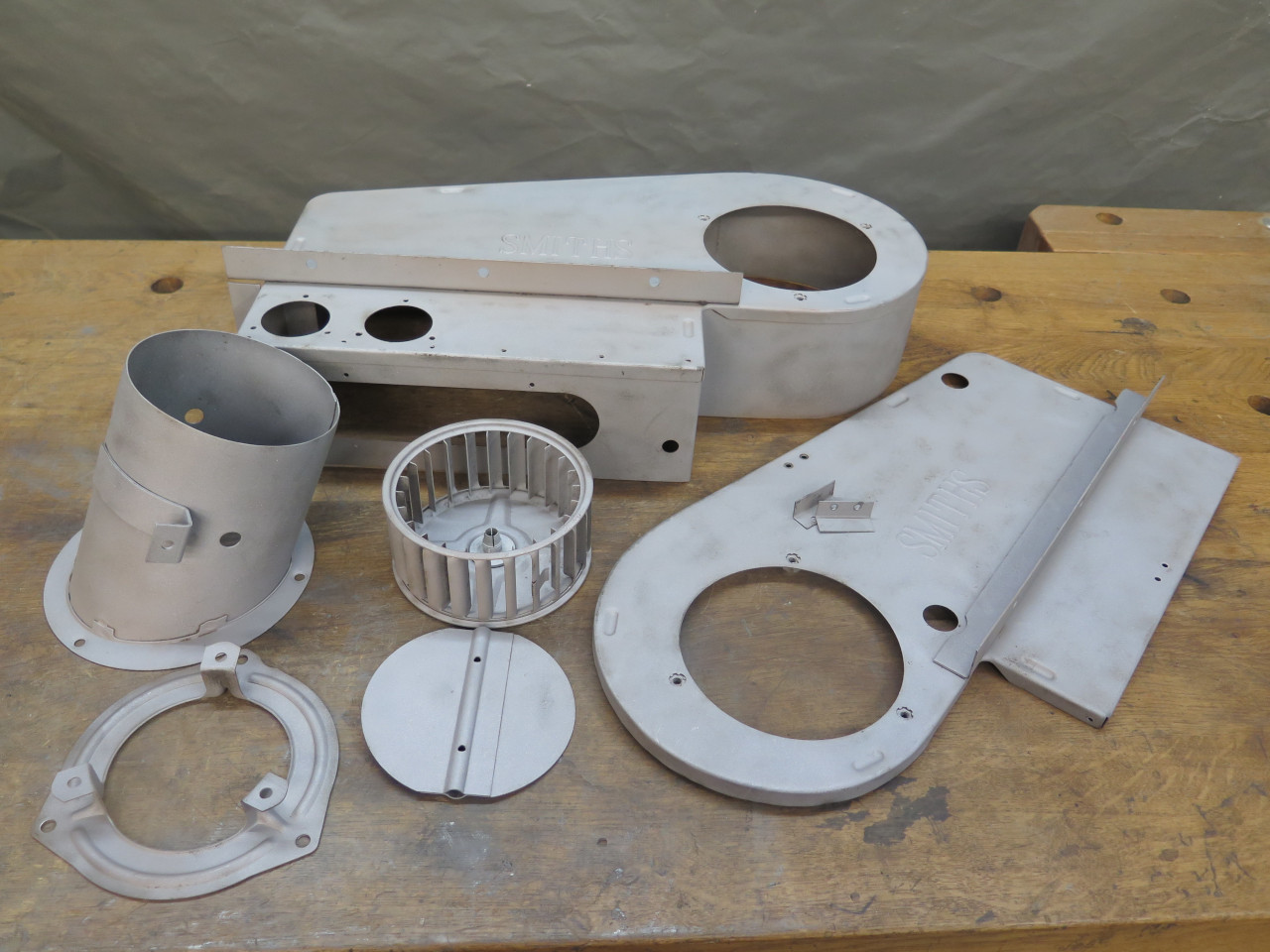
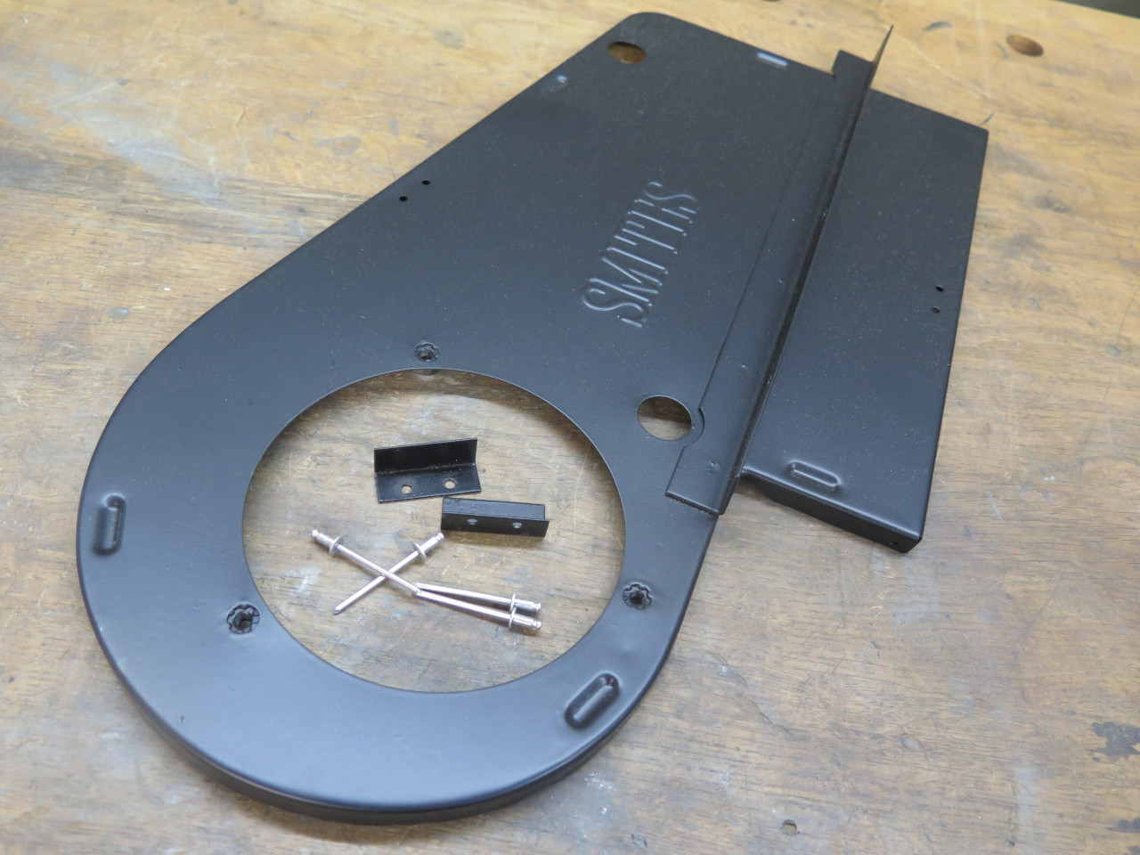
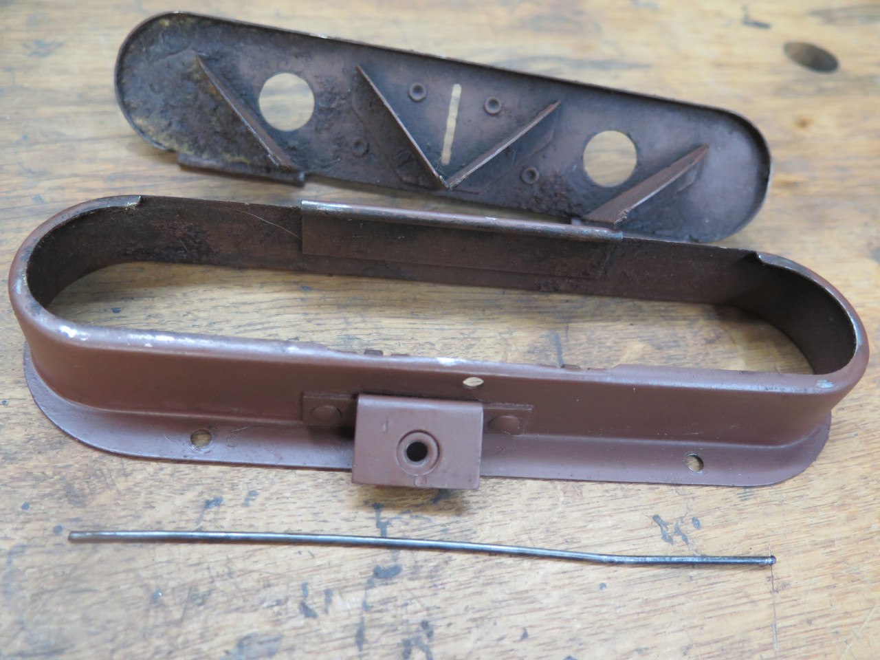
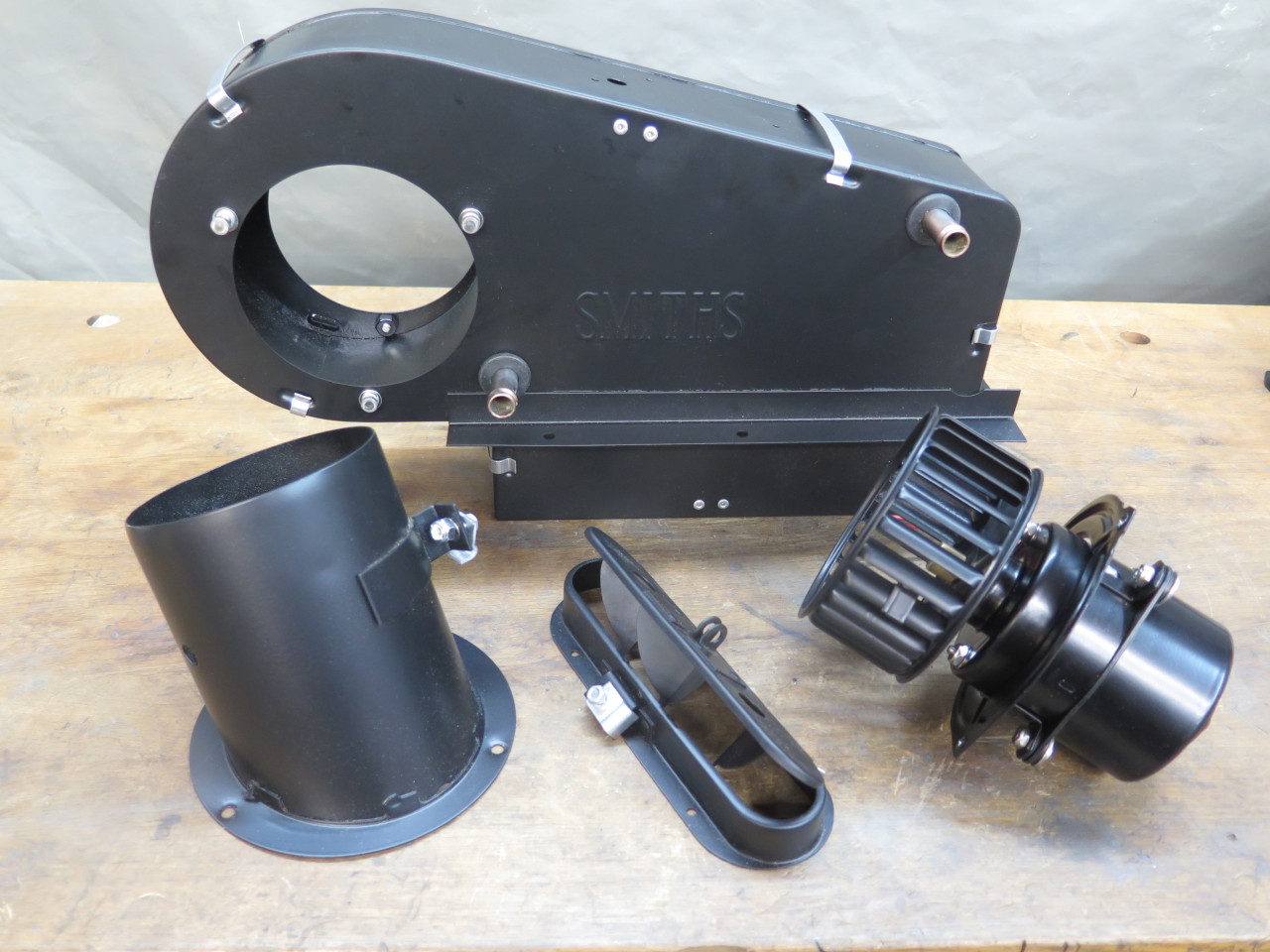
I separated it into its major components.

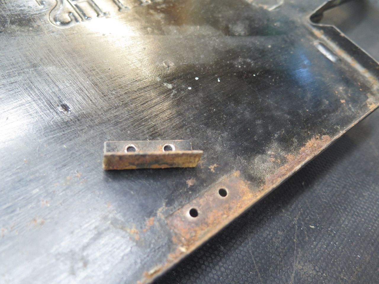
In preparation for blasting, I removed these little guide tabs from the front cover.
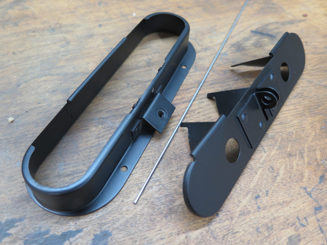
Blasted all the sheet metal parts.
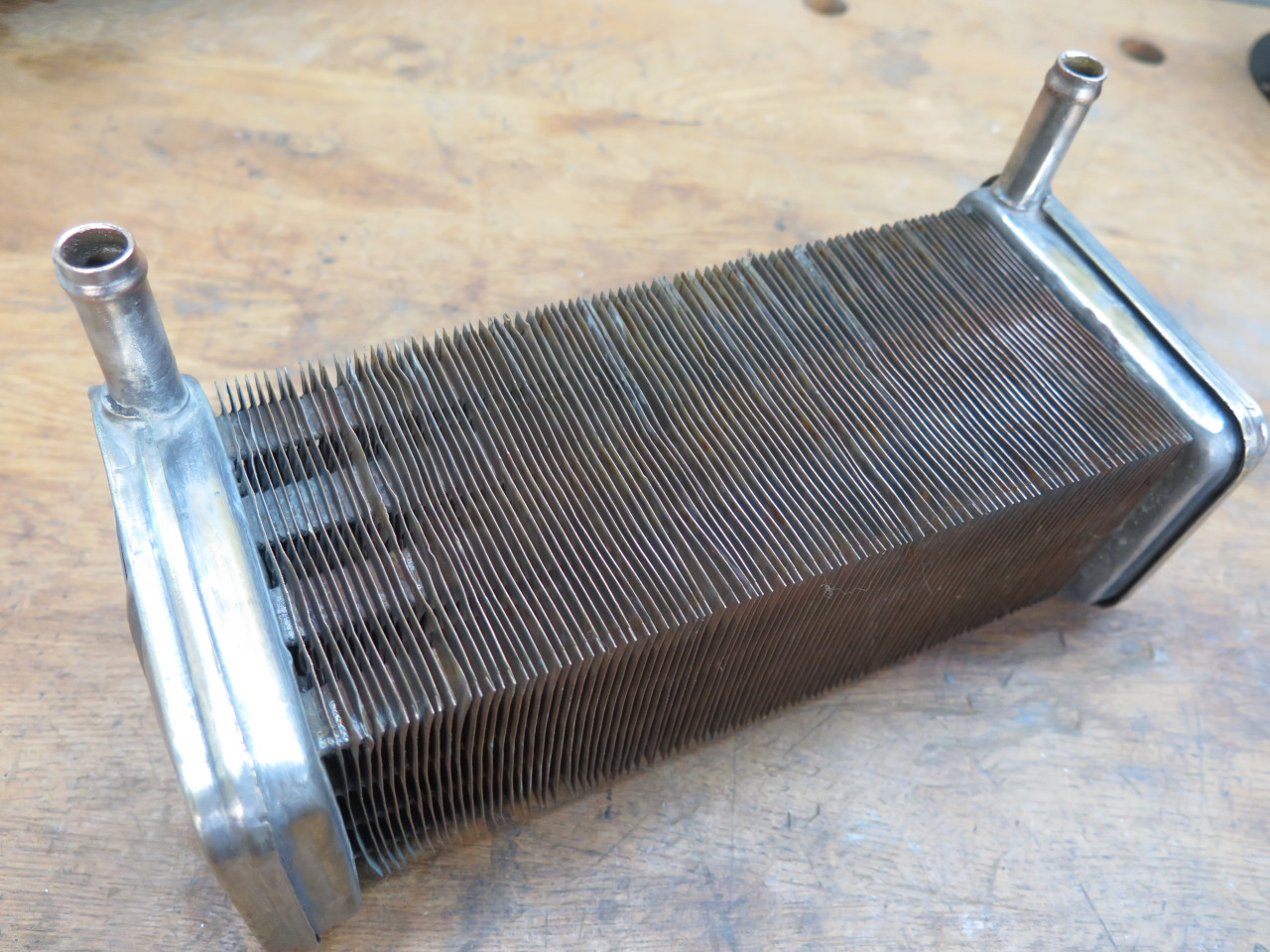
Before I started to reassemble anything, I had to know if the heater
core was good enough to use. I removed the resilient sealing
strips on the broad sides.

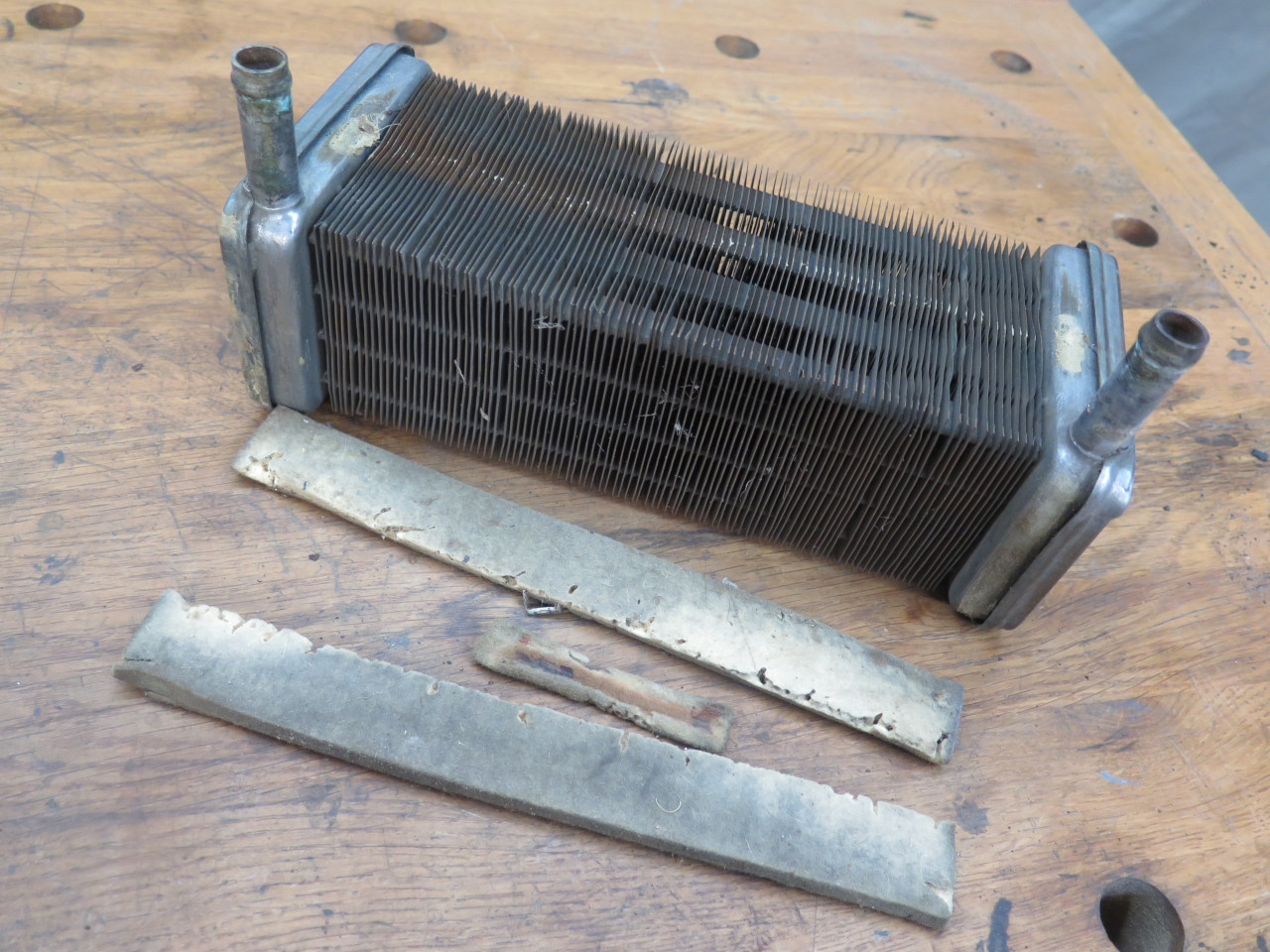
One end appeared to be bulged out. I don't know if this is normal, but it was certainly a cause for concern.
I flushed the core with hot water for a while. It ran clear almost
from the beginning. I then filled it with a phosphoric acid
solution to see if it would loosen any accretions inside. It did
produce a minor amount of dark scaly stuff, but not much.
As a gross test of integrity, I attached a hand air pump to one port, and a pressure gauge to the other.
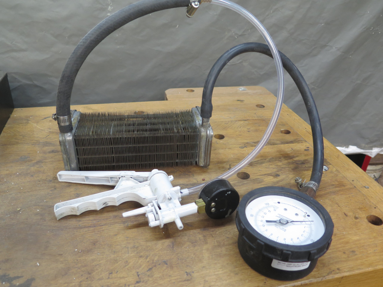
It appeared to hold pressure OK, but the real decider would be the bubble test.
So, in to by shop sink under a few inches of water.
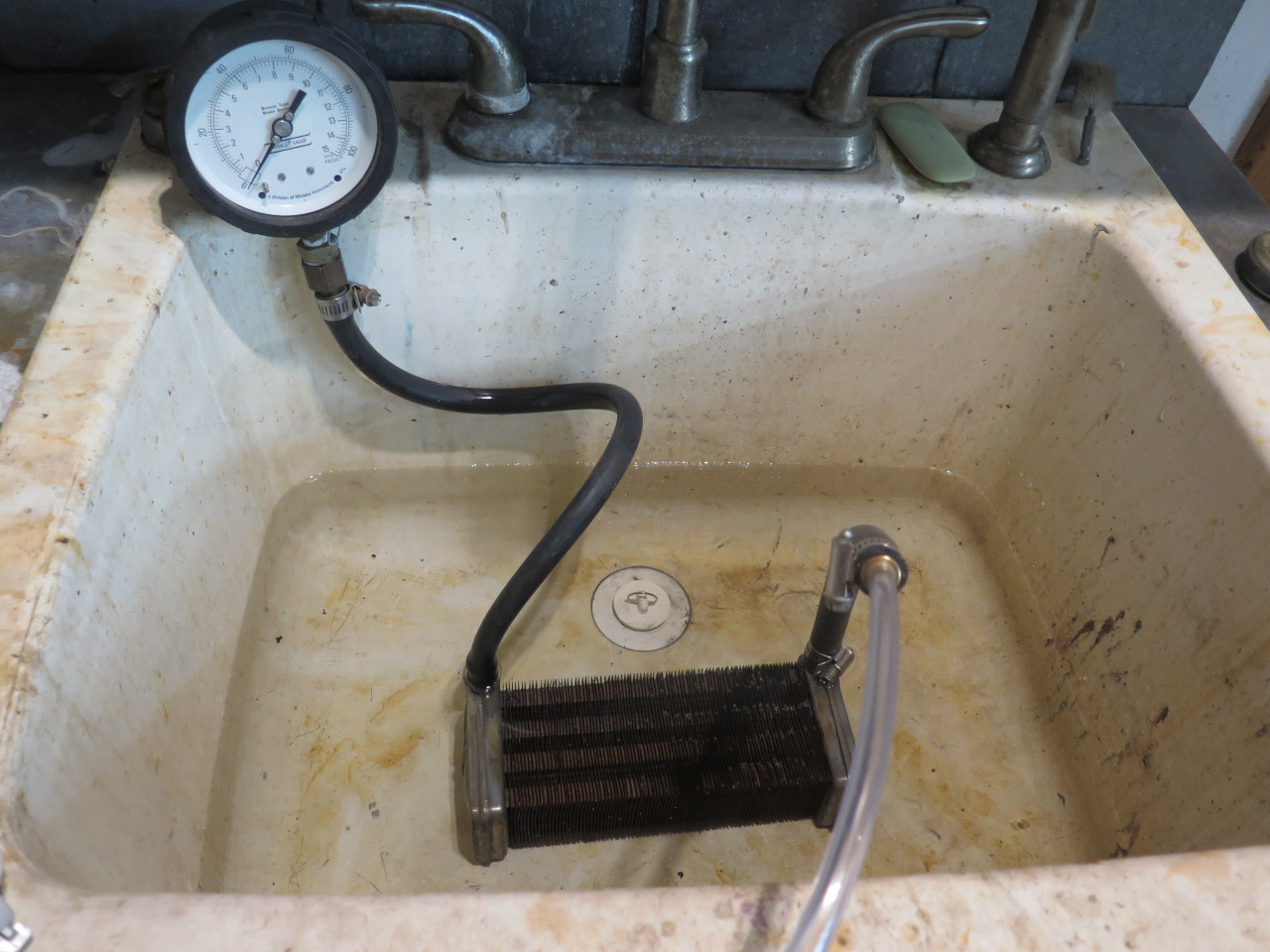
The cooling system pressure spec for early MGAs, including mine, is
apparently 4 PSI, and for later ones, 7 psi. I tested the core to
10 PSI. The pressure held steady, and there were no bubbles.

So, with an apparently serviceable core, I did a little more cosmetic cleanup.
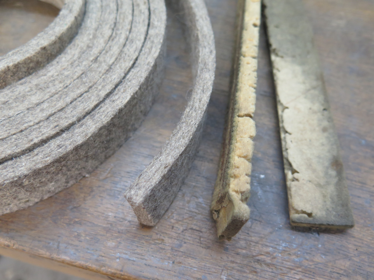
The sealing strips make sure that air has to go through the core fins,
and can't go around it. I used a firm felt material that matched
the dimensions of the originals.

The core mounts on the heater's cover plate. It got fresh paint, and new grommets for the core ports.
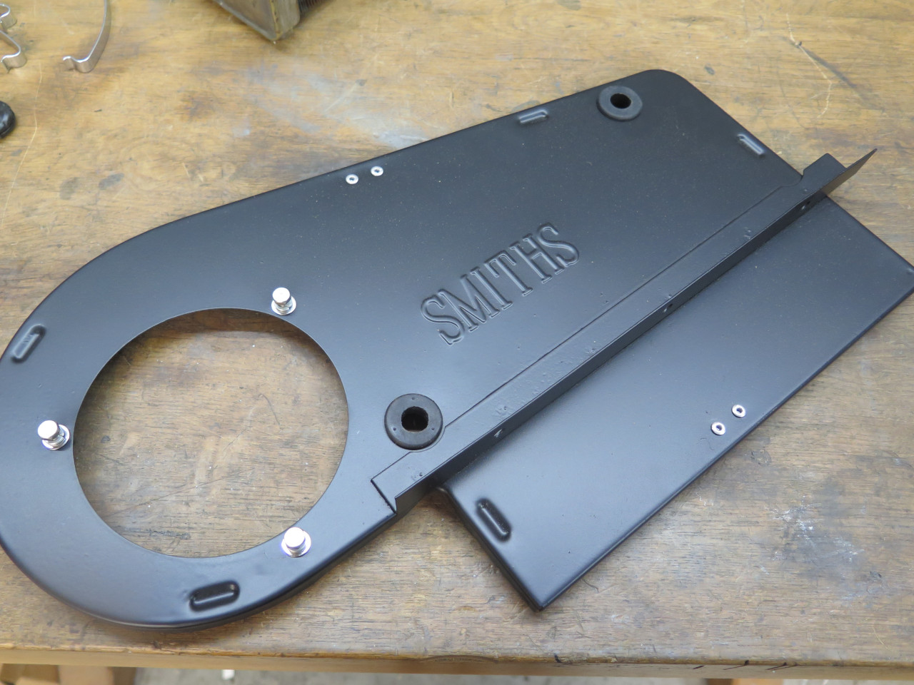

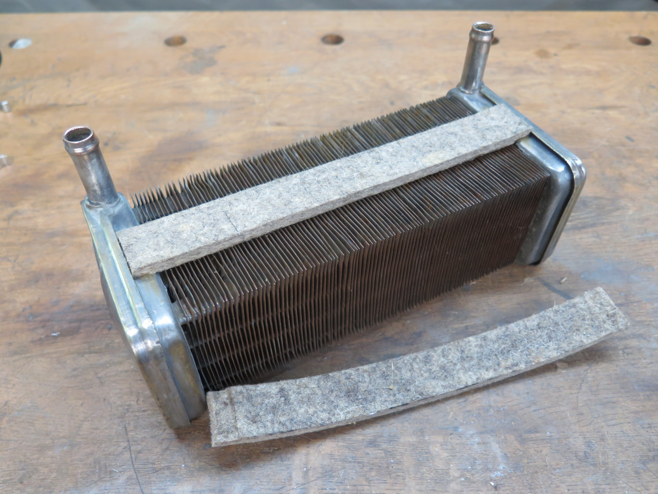
The heater's main body has some flanges that locate the core. Felt gets put on them, too.
Then the two pieces capture the core.
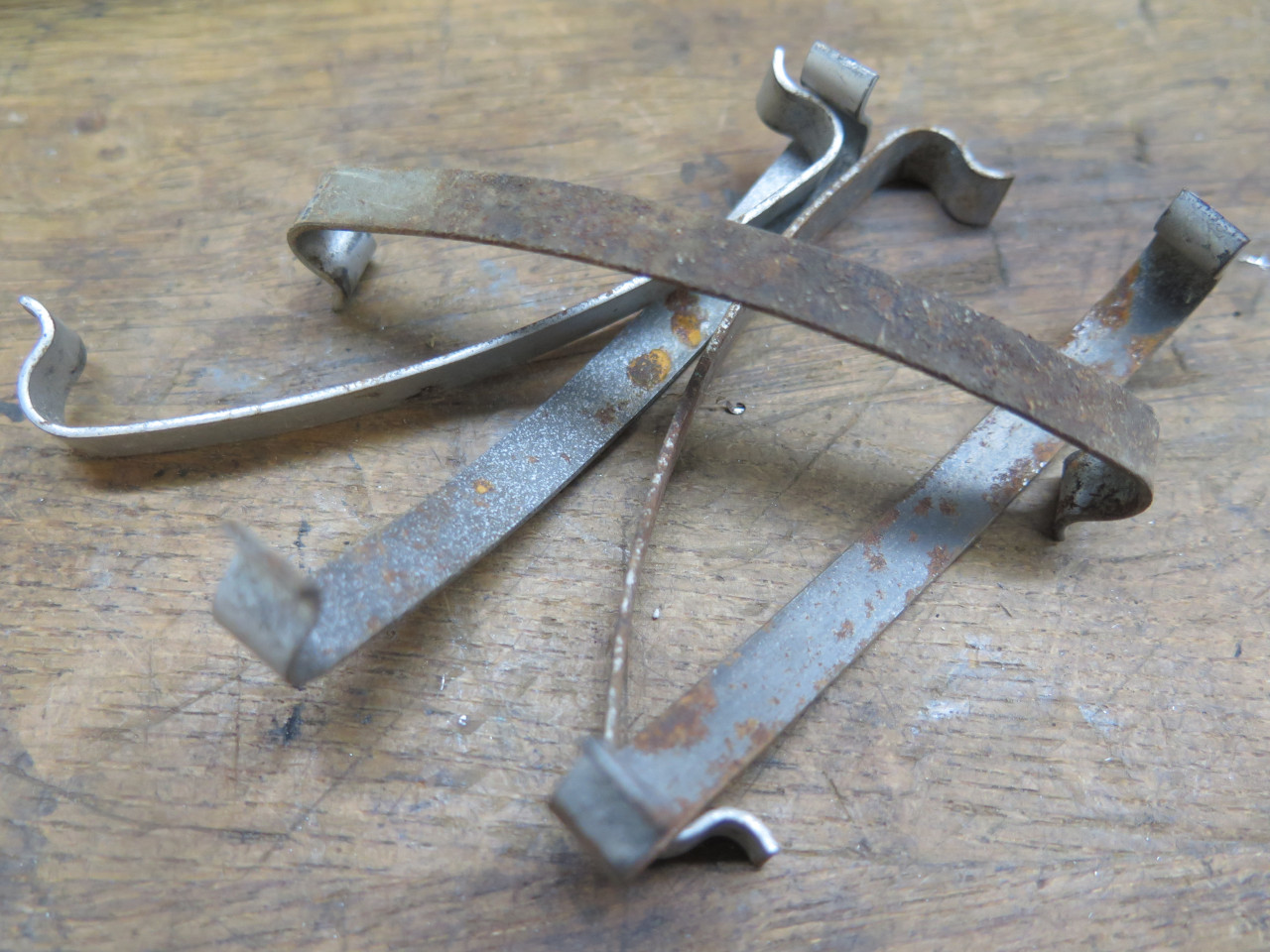
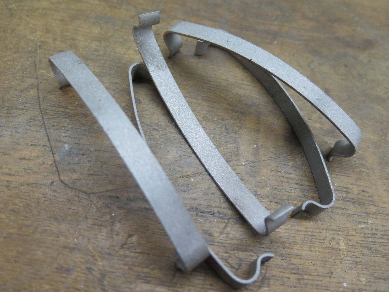
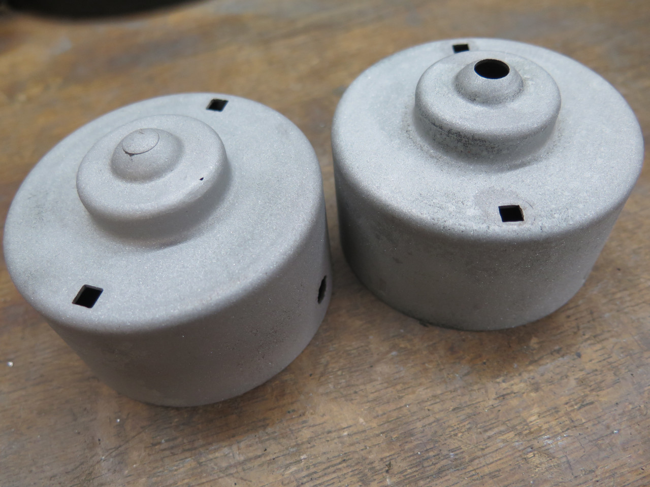
The main body and the cover are held together by five spring
clips. I would normally replate pieces of this size, but spring
steel can be problematic. It can be susceptible to hydrogen
embrittlement without special post processing. In this case, I
opted to just blast the parts and powder coat them silver.
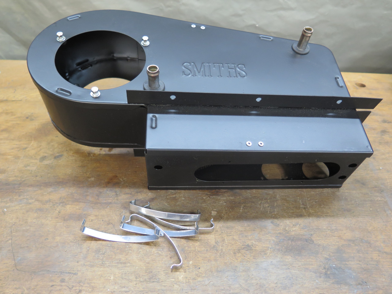
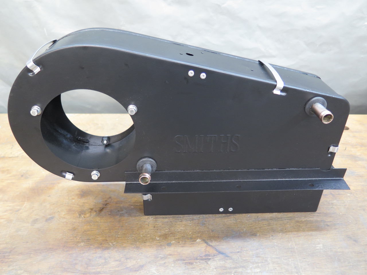
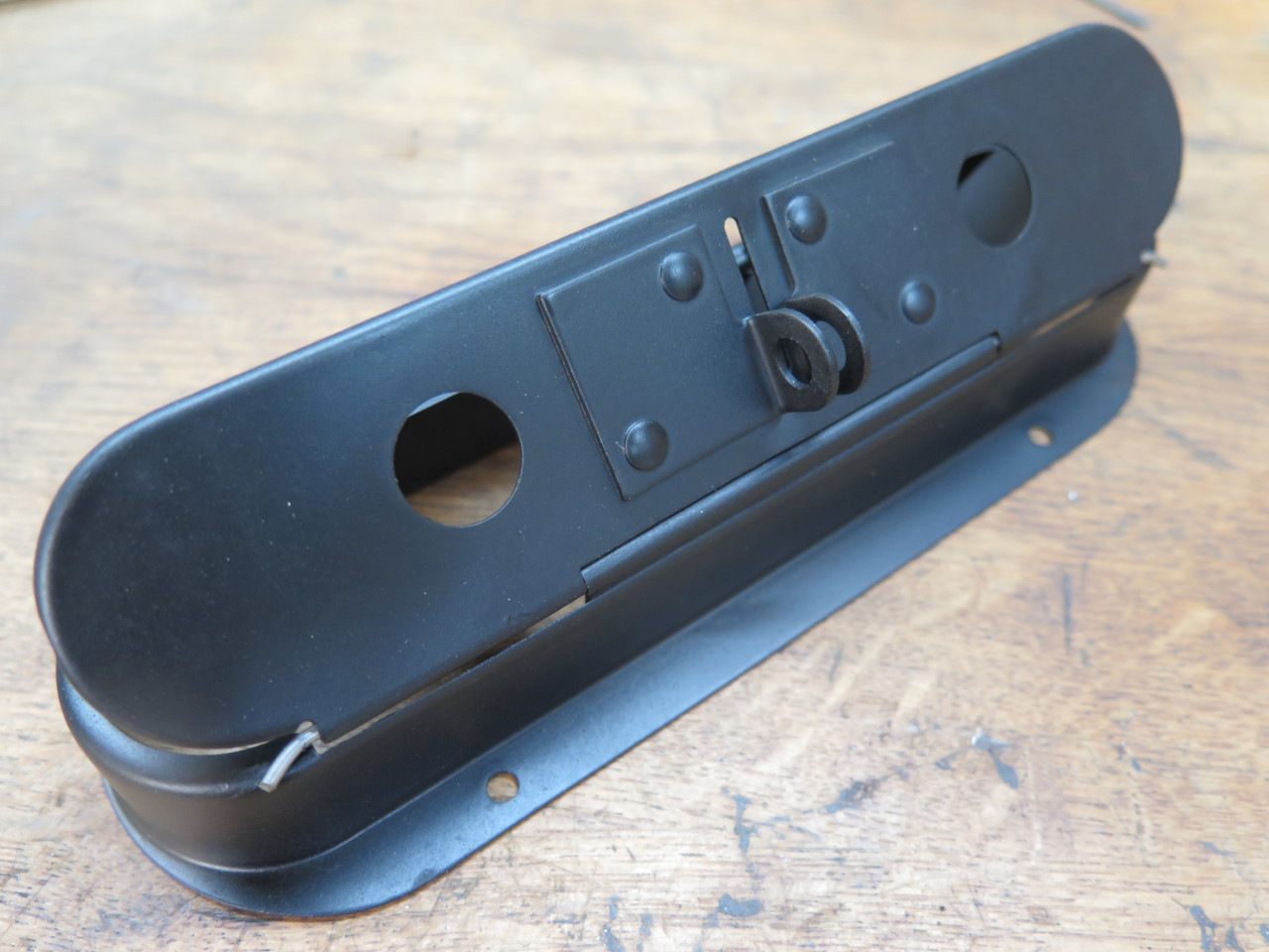
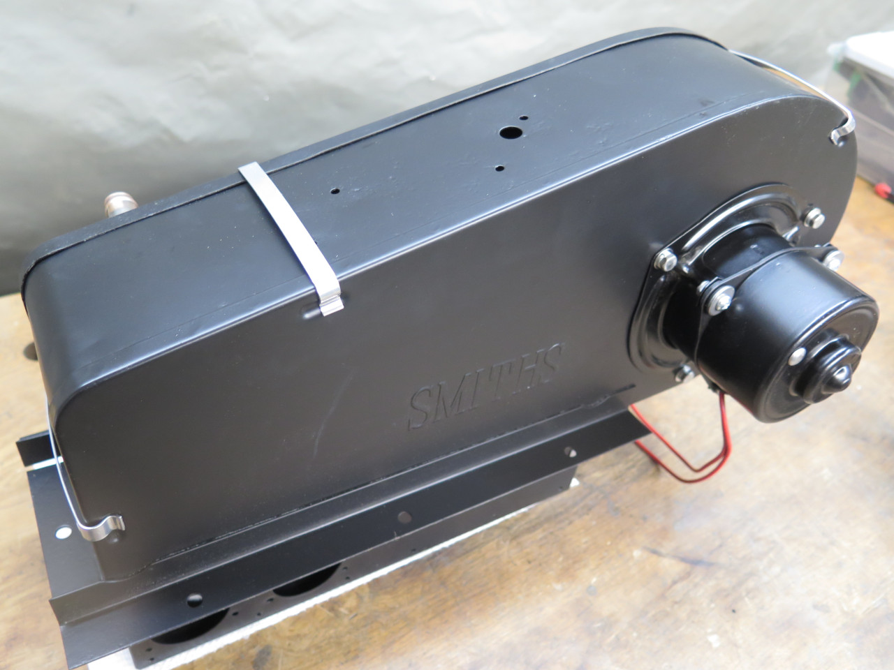
The heater's main body...
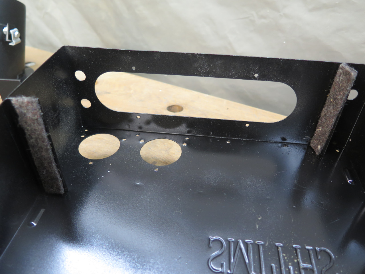
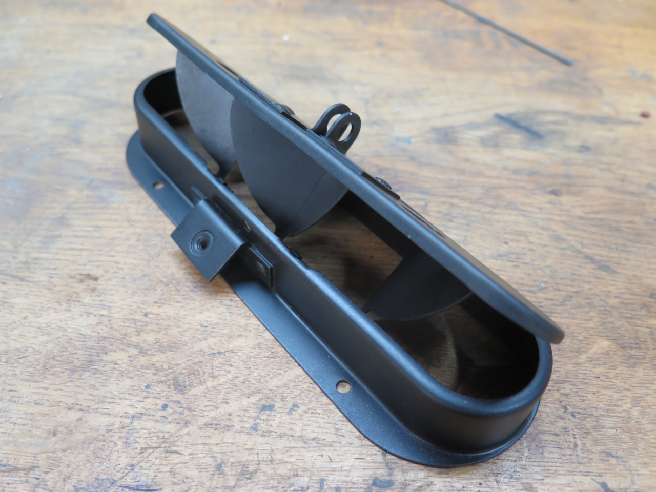
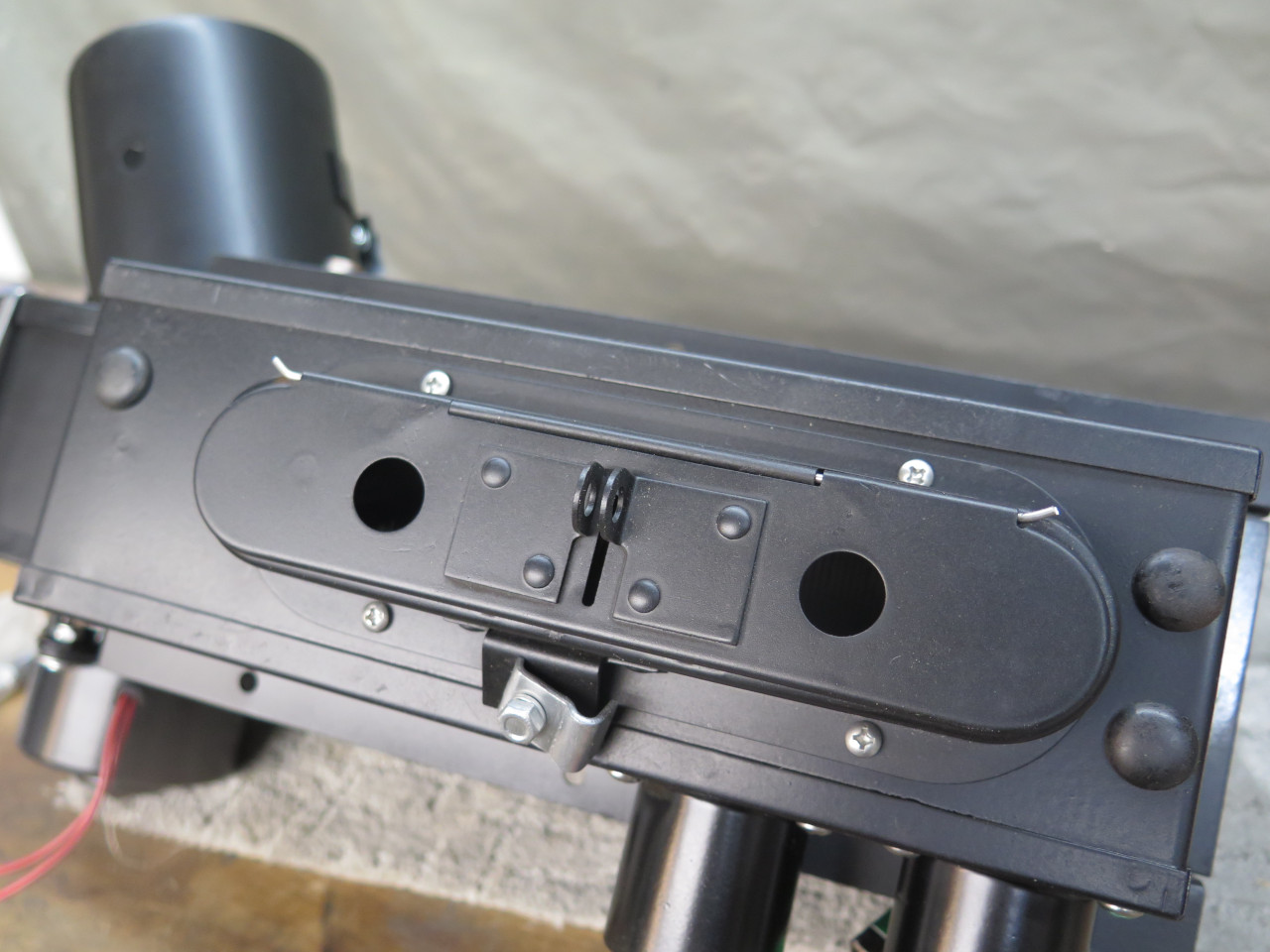
The next assembly I looked at was the little air door at the bottom o
the heater. When the door is open, air is released into the foot
wells. When closed, air is forced into the defroster ports.
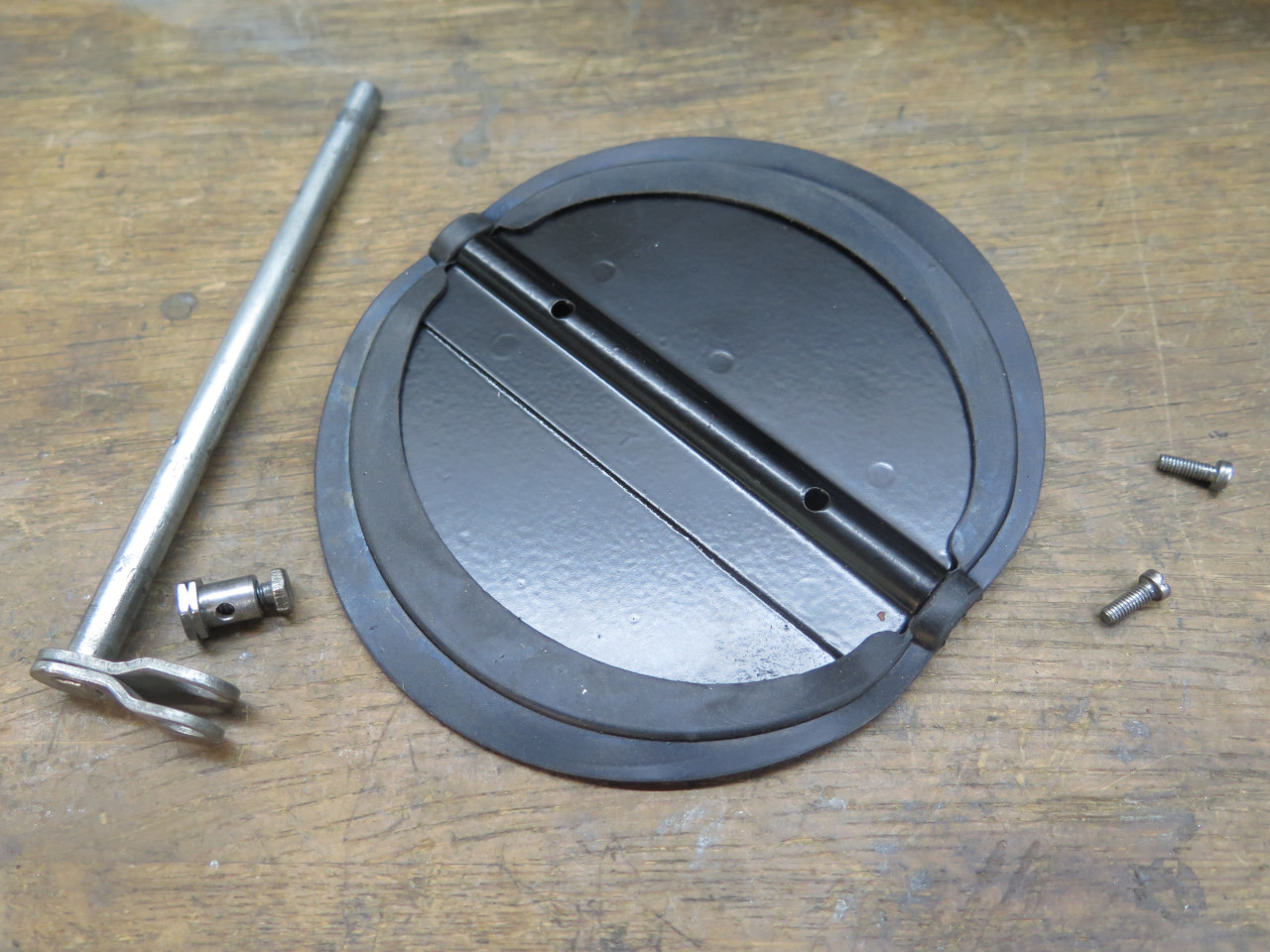
Te door was essentially seized. Forcing it was flexing the hinge
part of the door. I was afraid it would break the hinge.
Over time and with copious amounts of penetrating oil and encouragement,
I got the door to move, but it was still very tight. I decided to
try to remove the hinge pin. It wasn't easy.
After blasting and powder coating, ti got a brand new straight stainless steel hinge pin. The door works effortlessly now.
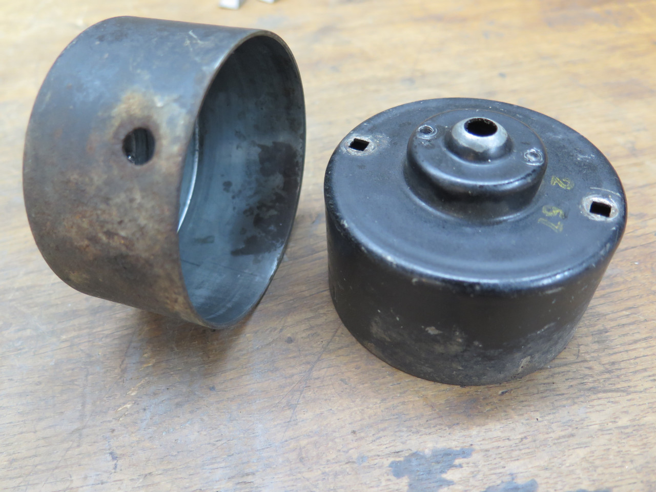
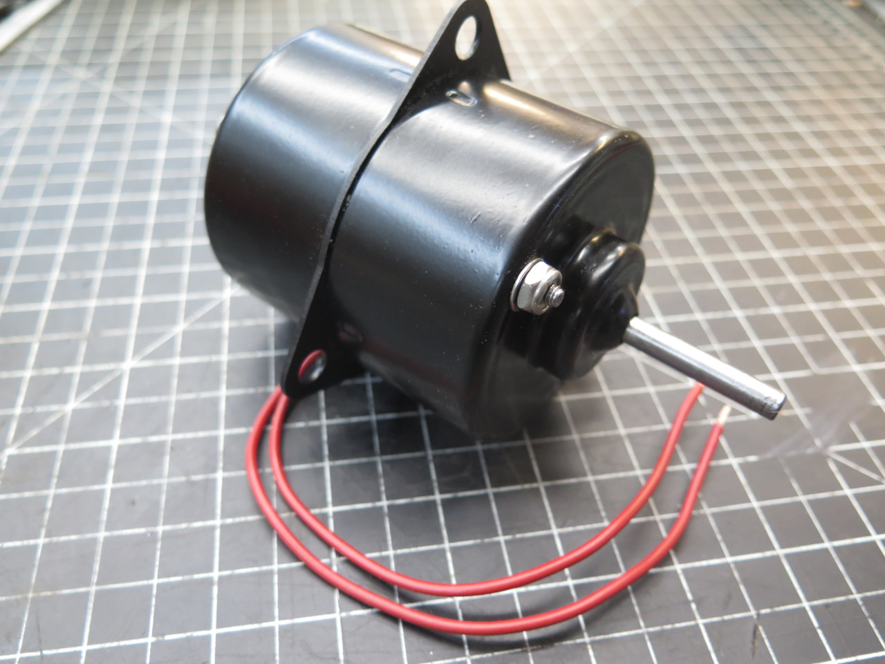
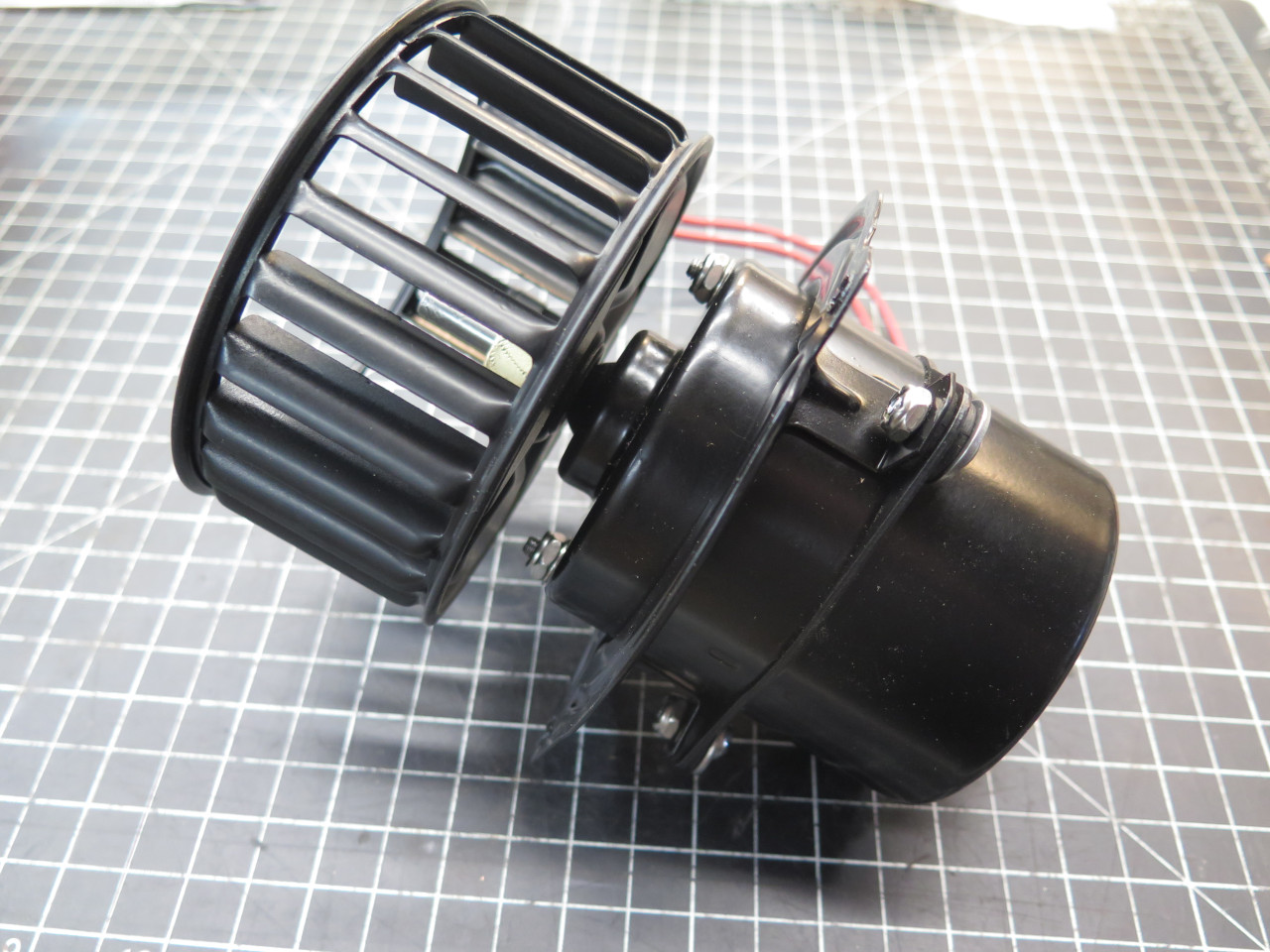
Then I came to the blower. I broke it down to just the motor.

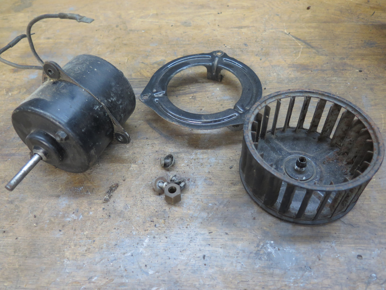
I hooked it up to a 12 volt power supply. It ran, but sounded like
nails in a coffee can, with a hint of squawking. So, apart it
came.
I discovered that this is a series wound universal motor. All of the windings looked OK, with no evidence of overheating.
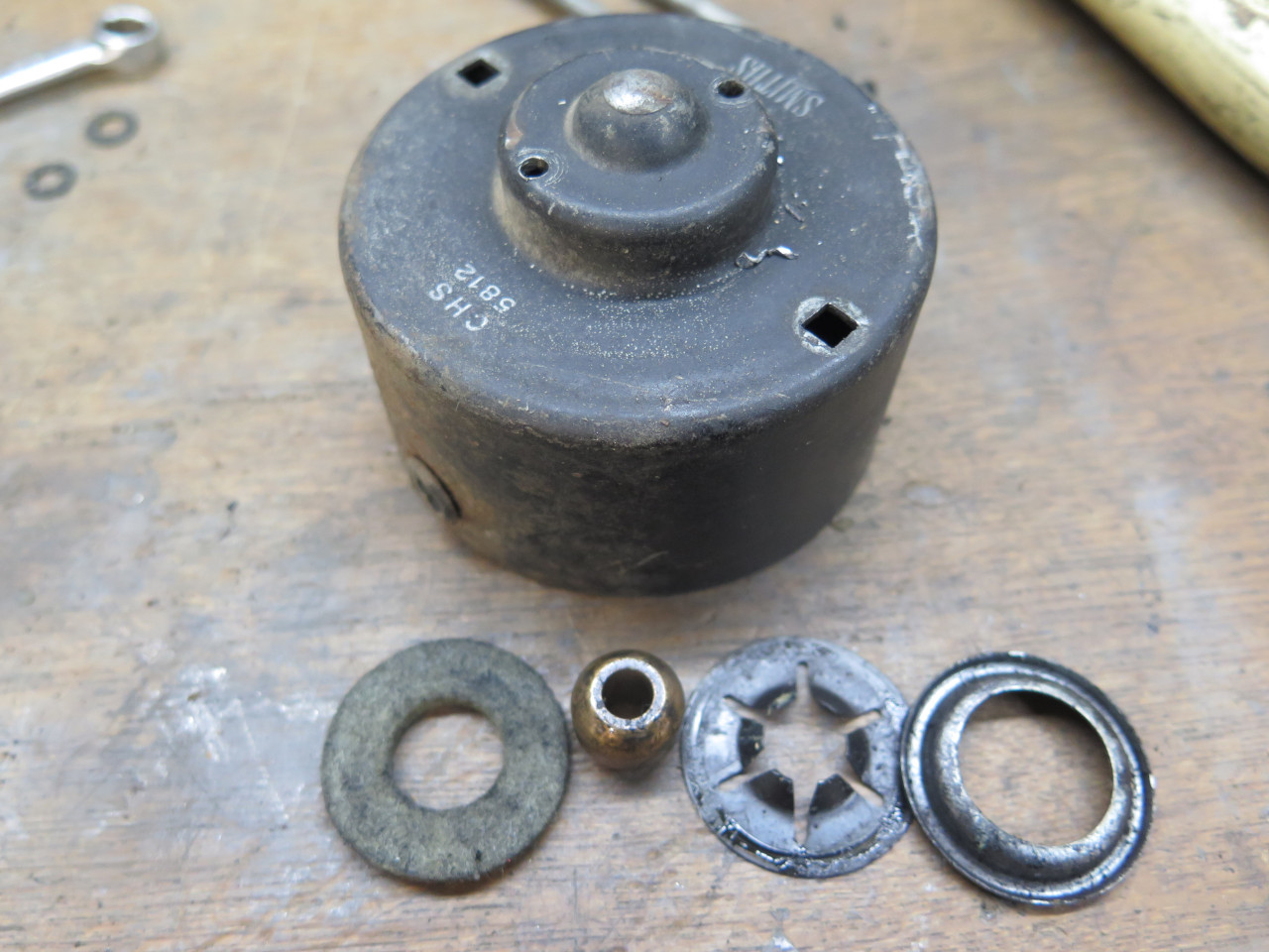
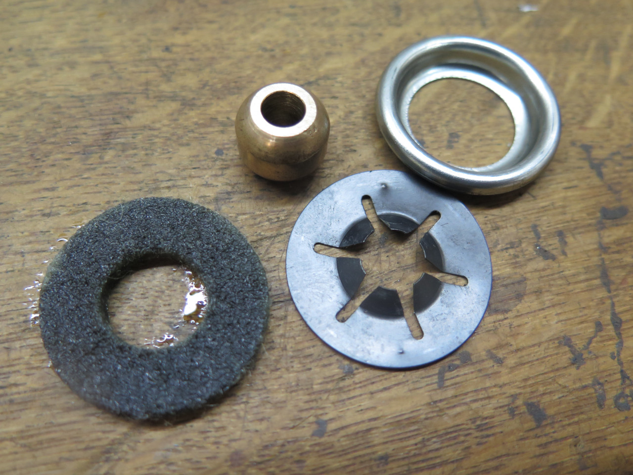
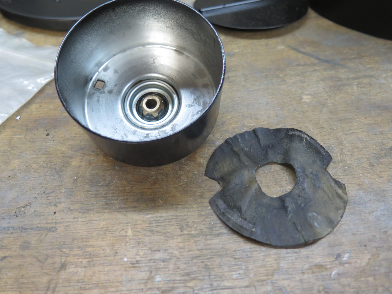
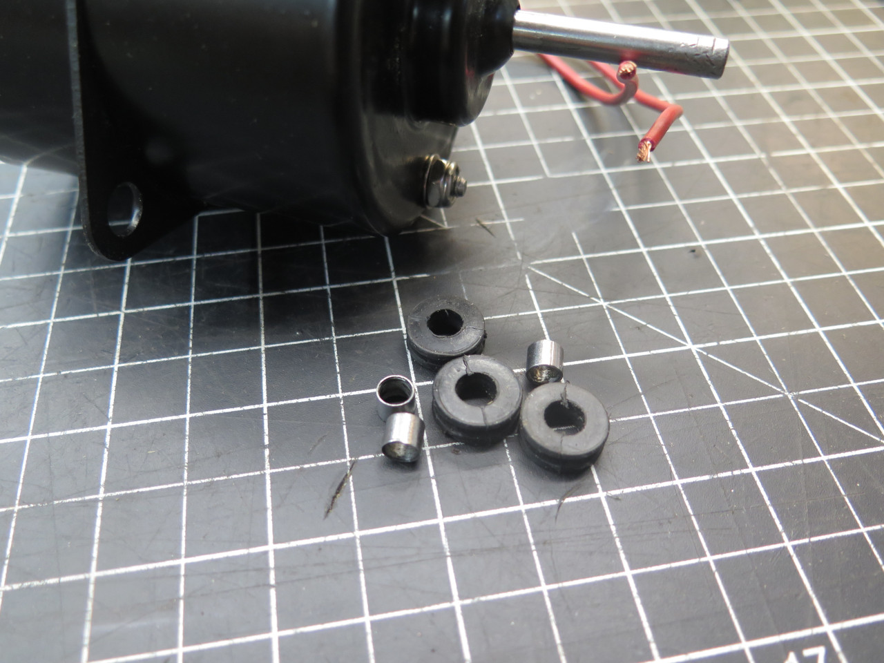
The noise problem seemed to be that the bushings at each end of the
motor housing were worn, and allowed quite a bit of play. These
are self-aligning bushings, consisting of a spherical sintered bronze
bush held by a fingered spring such that it can rotate a small amount in
any direction. I figured I didn't have much to lose, so I knocked
one of them out. There is also a felt pat that holds a reservoir
of oil, and a retainer ring that keeps everything in place.
Now, I suppose that somewhere I might be able to buy these spherical bushings, but a half-hearted search turned up nothing.
But I had another idea. I ordered some ordinary sintered bronze
bushes with an ID if 1/4" (that's the armature shaft diameter), and
5/16" OD.
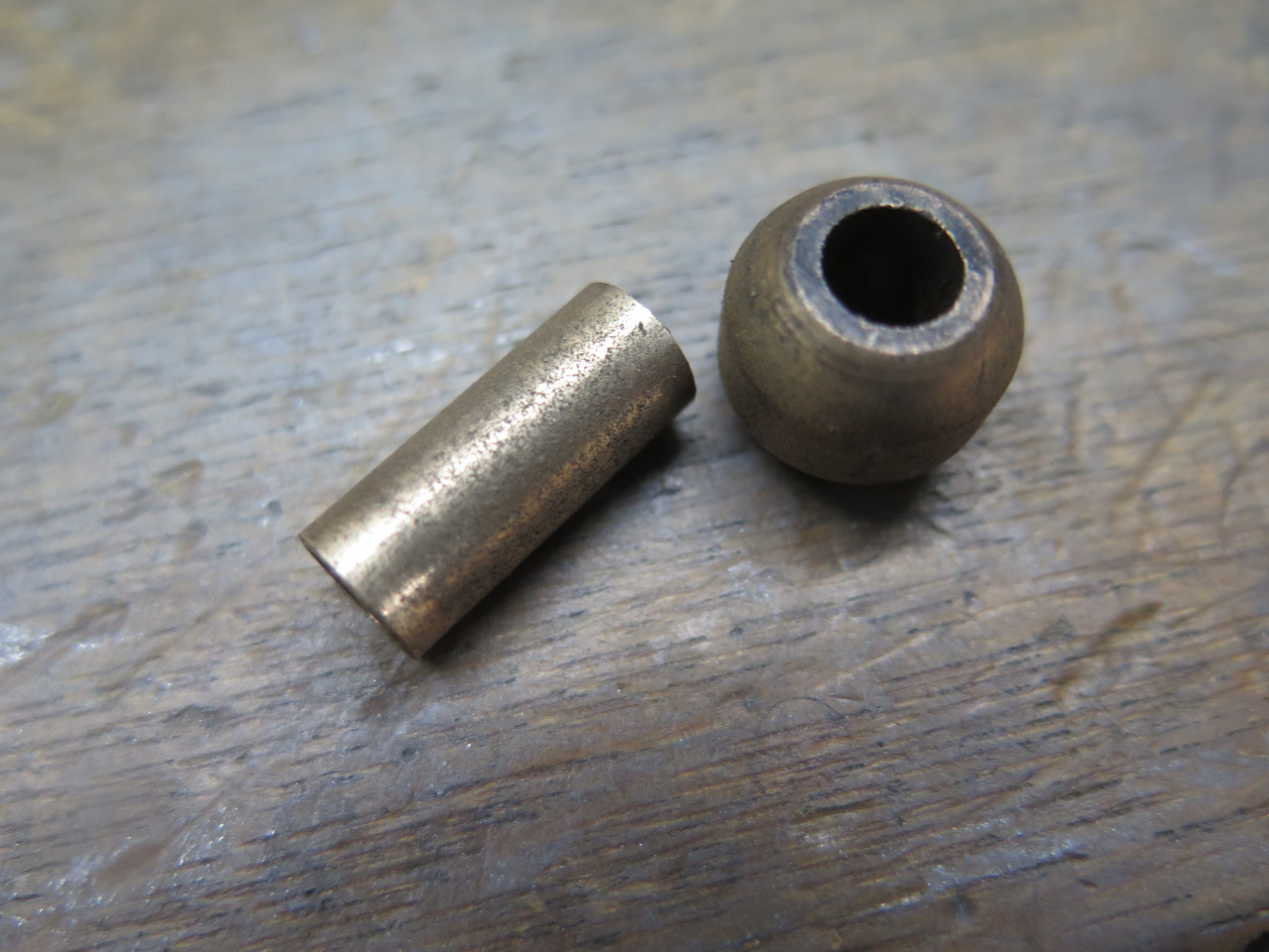
Then drilled and reamed the spherical bushes to 5/16". The
straight bushes were a firm press fit into the spherical ones.
Then just trimmed to length. They were then a much better fit on
the armature shaft.
Sintered bushings are made by compressing powdered metal into a solid
shape, but leaving some small space between the metal granules.
That space, which could amount to 15% or so of the bushing's volume,
serves as a reservoir for oil. The porosity allows oil to travel
through the bulk of the bushing.
To make sure the bushing starts out with as much oil as possible, and
maybe to clean out some of the nearly 70 year old oil from the original
bushing, I did a vacuum treatment on the bushings. By subjecting
it to a fairly deep vacuum, any air in the pores of the metal will
expand and be expelled. If it's done in an oil bath, the exiting
air will be visible as bubbles. Then, when the vacuum is released,
atmospheric air pressure will force oil into the pores.
Initially, there was general foaming of the oil, but this was probably
mostly just air dissolved in the oil. Later, the bubbling slowed
down and became localized over the bushings. A plume of darker oil
formed around the bushes, presumably ancient oil from the 50s.
I wish I had thought to weigh the bushes before and after the treatment.

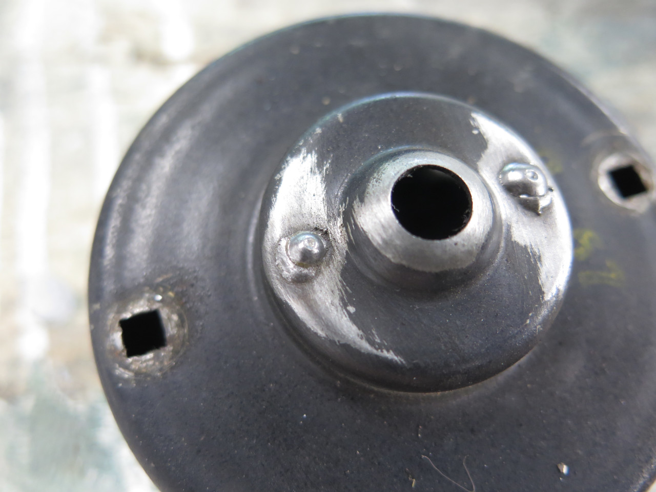
Before re-installing the bushings, I cleaned up the two halves of the
motor housing, including welding up the holes I drilled to pop the
bushings out. Then a nice powder coat.
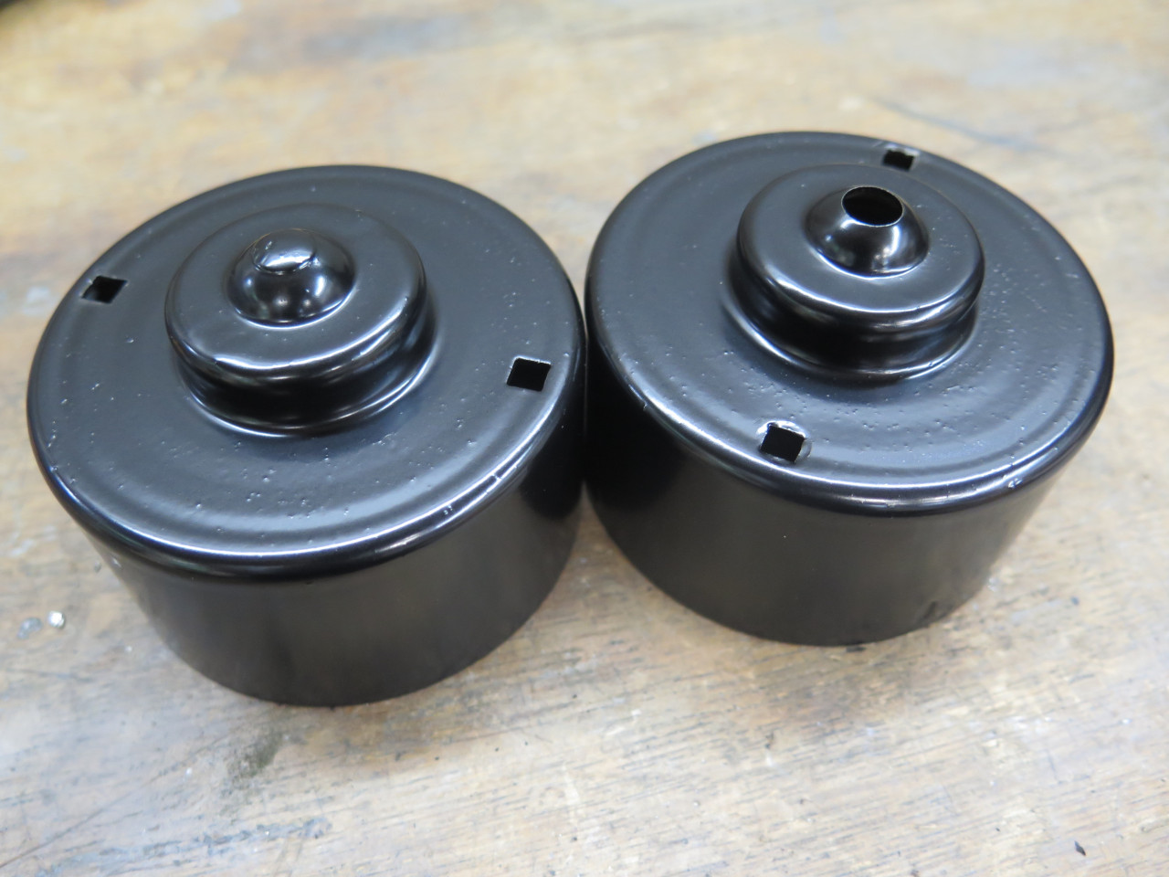
I soaked the felt pads with fresh oil, dropped everything into the housings, and pressed in the retainer ring.
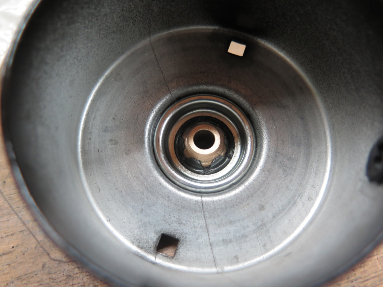
The armature is now a nice smooth slip fit in the bushing.

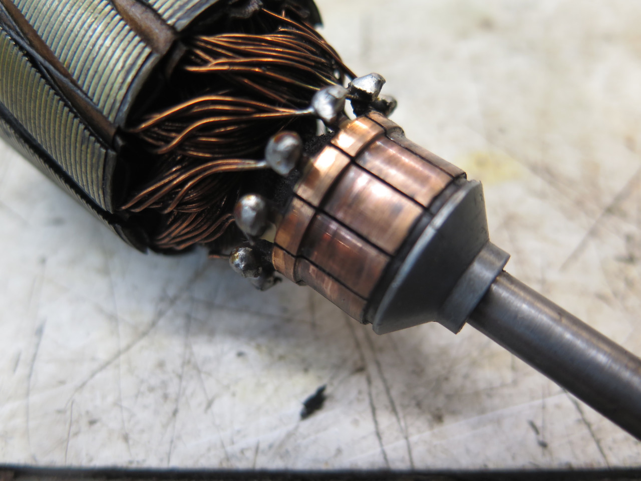
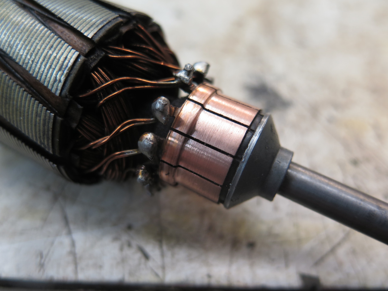
At some point in this process, I had cleaned up the commutator, though it wasn't that bad.
The commutator end housing was similar, but it also had an insulating
disc glued in, since the brush plate is in pretty close proximity.
I used so called "fish paper", which is designed for use around
electrical parts.

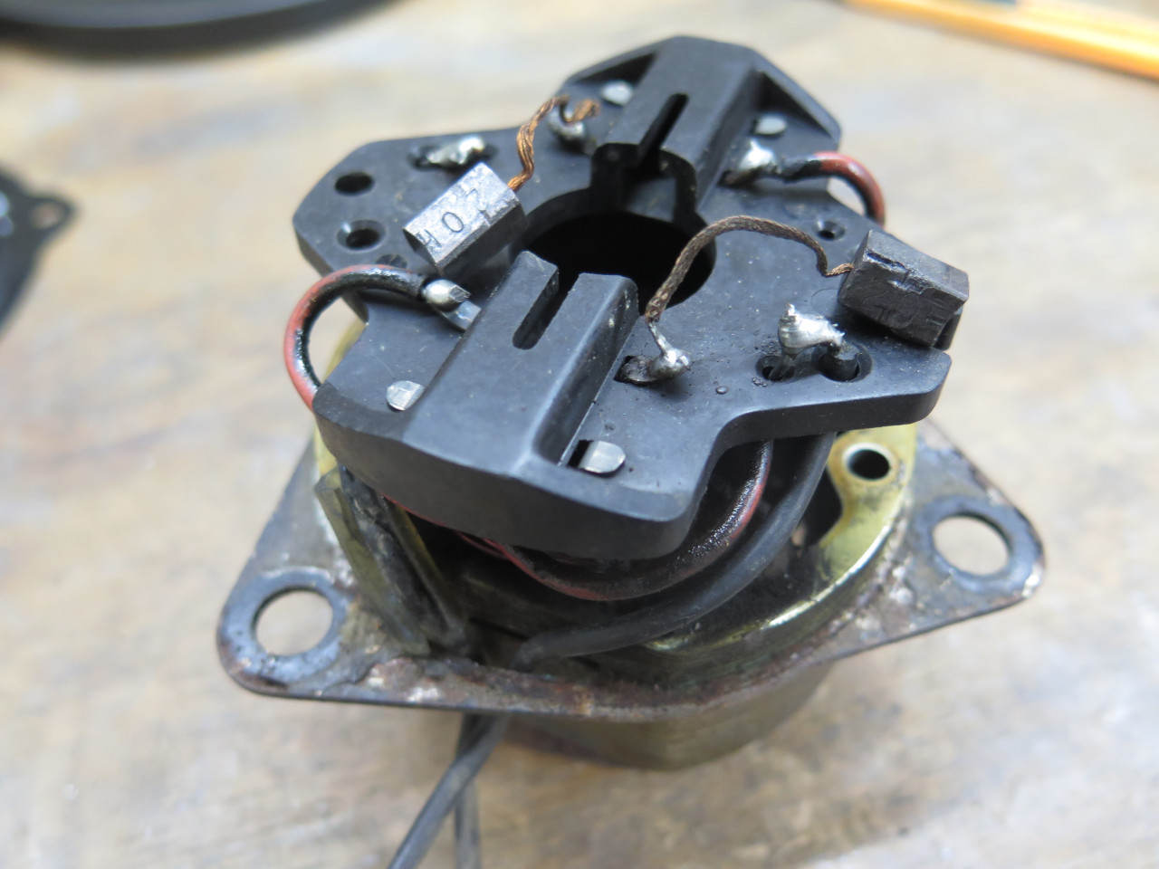
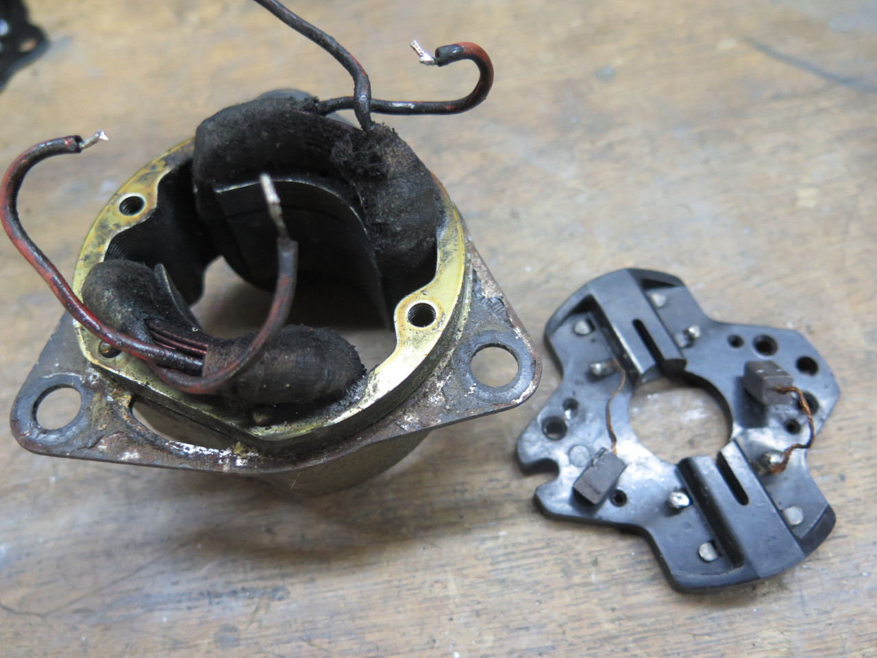
Then it was time for the brush plate. The brushes are carried by a
Bakelite piece that is held by the housing screws. I wanted to
clean and paint that triangular mounting bracket that is captured in the
stator core, and this would be way easier without the brush
plate. Unsoldering four connections allow it to come free.
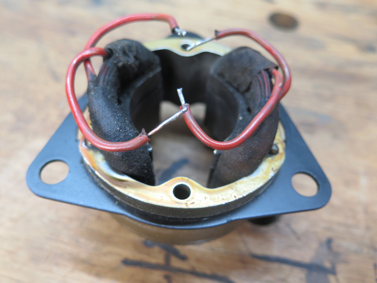
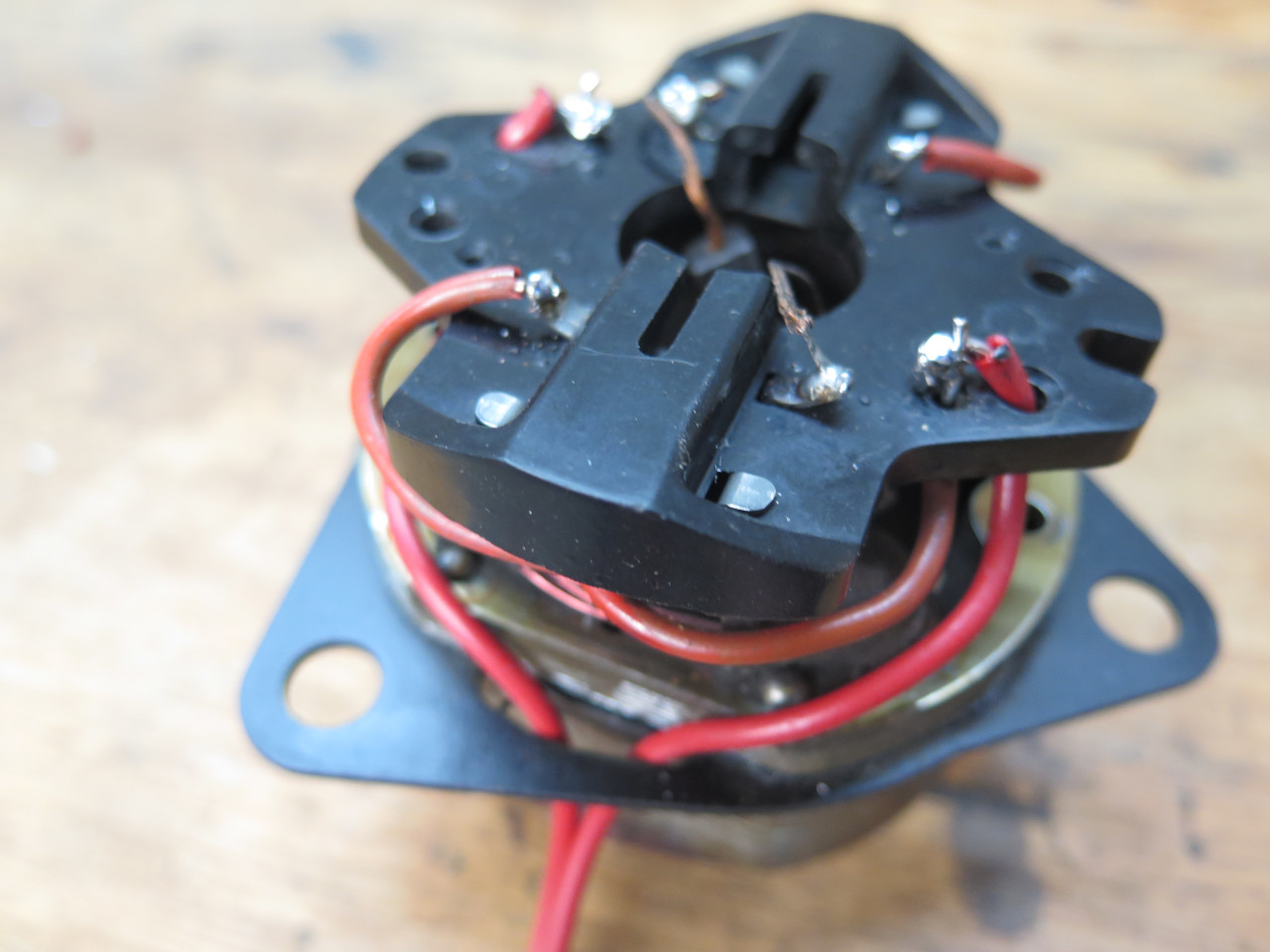
After painting, I cleaned up the wires a little, and resoldered the
plate, also took the opportunity to change the lead wire color to red
from the original black. Black wires suggest ground connections,
and another color seemed more appropriate to me. The motor is not
polarity sensitive, so the wires can be the same color. The
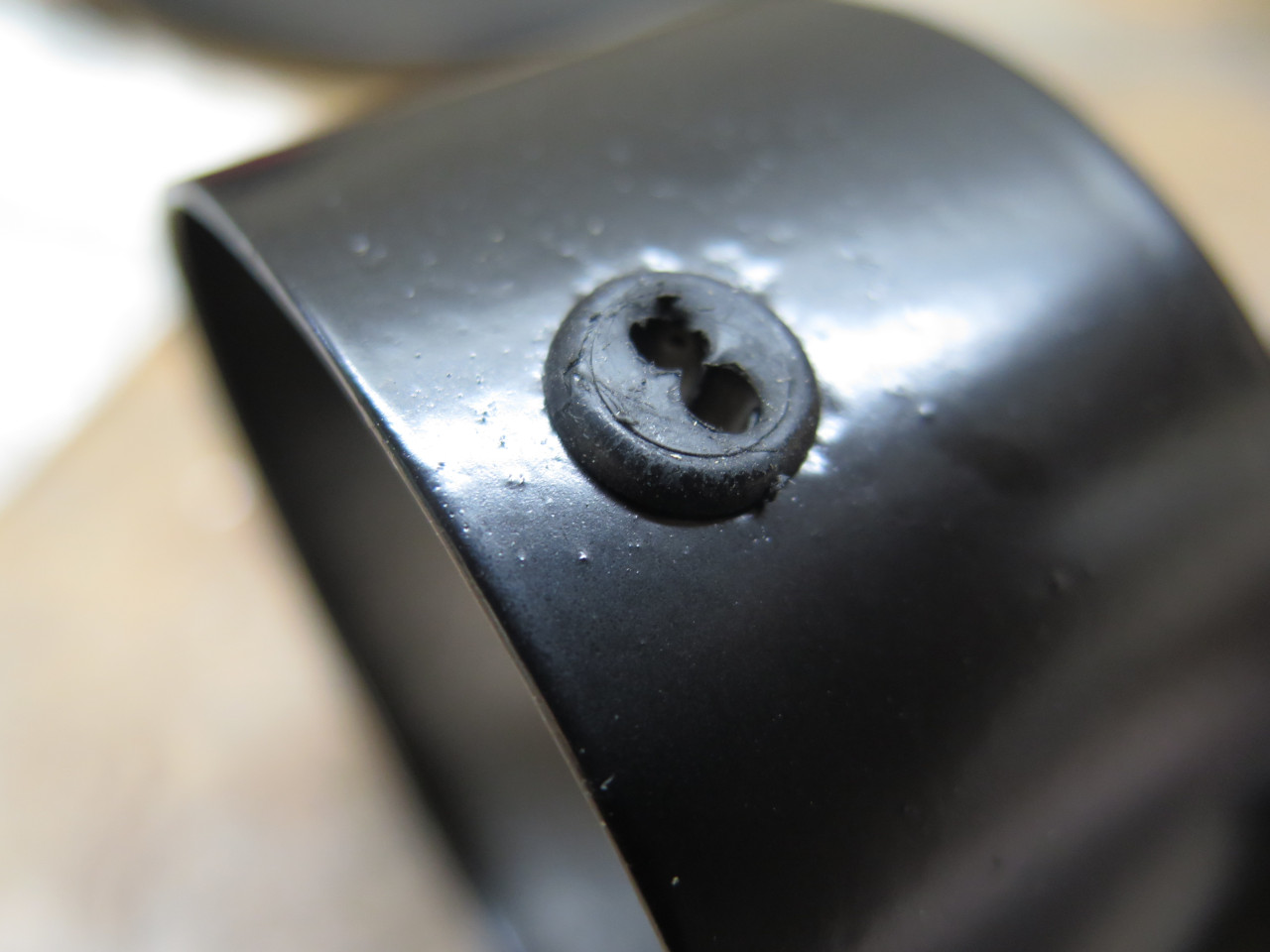
external leads go through this little dual grommet, which was still fit
for use.
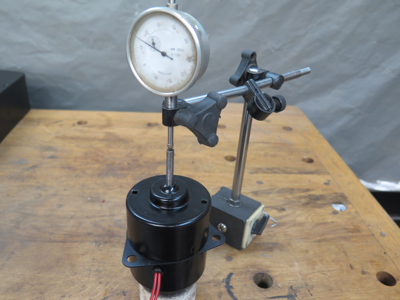
At this point, I did a dry run of the armature in the two cases, and
confirmed smooth rotation with no play, but this was mainly to measure
end float. It came out to be about 0.025". I don't know what
the spec would be for this, but 0.025 seemed like a lot, and I thought
it could have been contributing to the noisy operation.
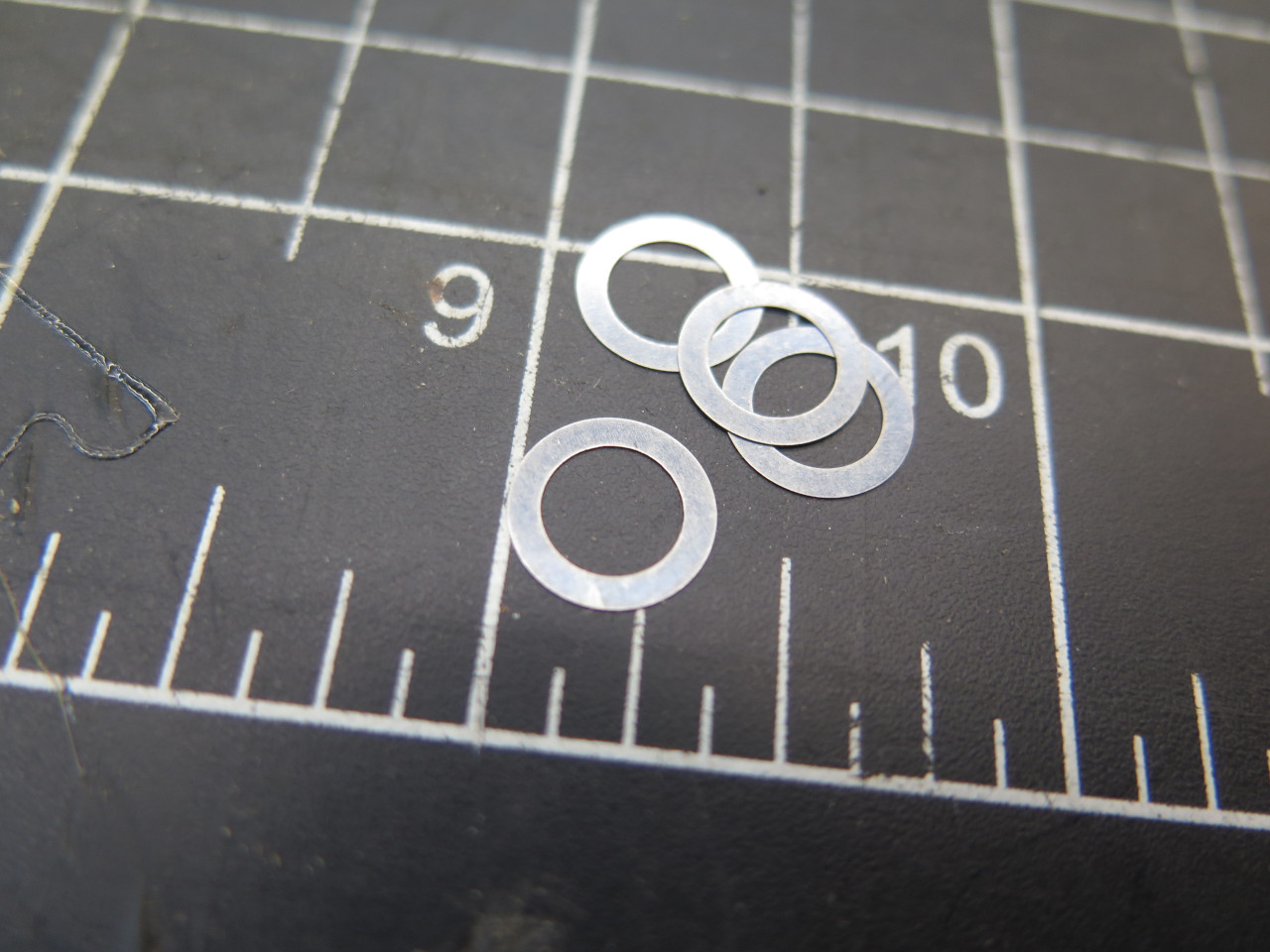
End float is set by small shims on the armature spindle. I'm not
sure how many were supposed to be there, but I only found one. I
got some 0.005" shims, and put four of them on the armature
spindle. That reduced play to around 0.005", which seemed OK.
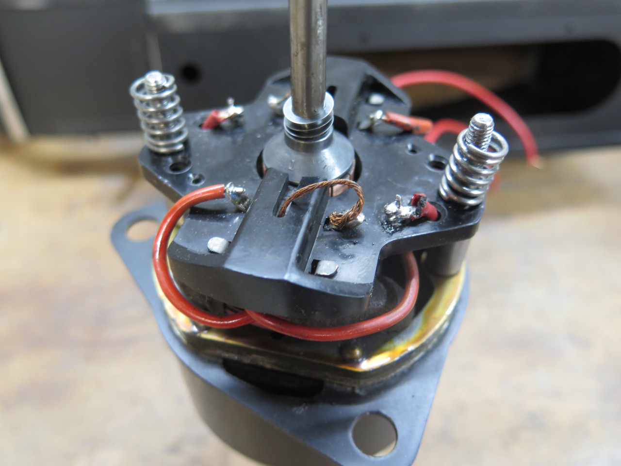
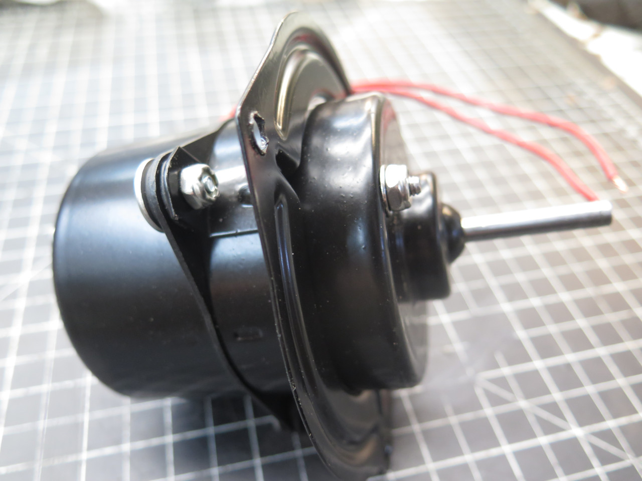
Then it was show time. I assembled the motor, set up the power
supply to 14 volts, hooked it up, and threw the switch. The motor
started instantly, ran for half a second, and stopped suddenly,
seized. It wasn't fully seized--I could turn it through part of a
rotation, and it would catch and refuse to go any further.
Here was the problem. I had apparently botched installing one of
the brush springs. It must have been hanging down below the brush
plate instead of being fully in the brush cavity. Something
snagged it.
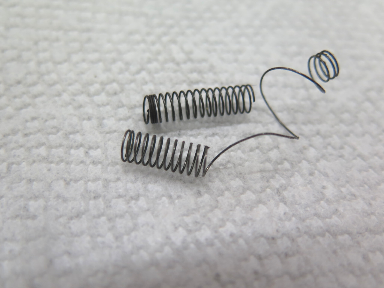
I pawed through my "tub o' springs" and found a few candidates.

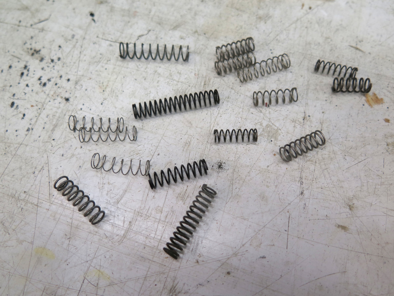
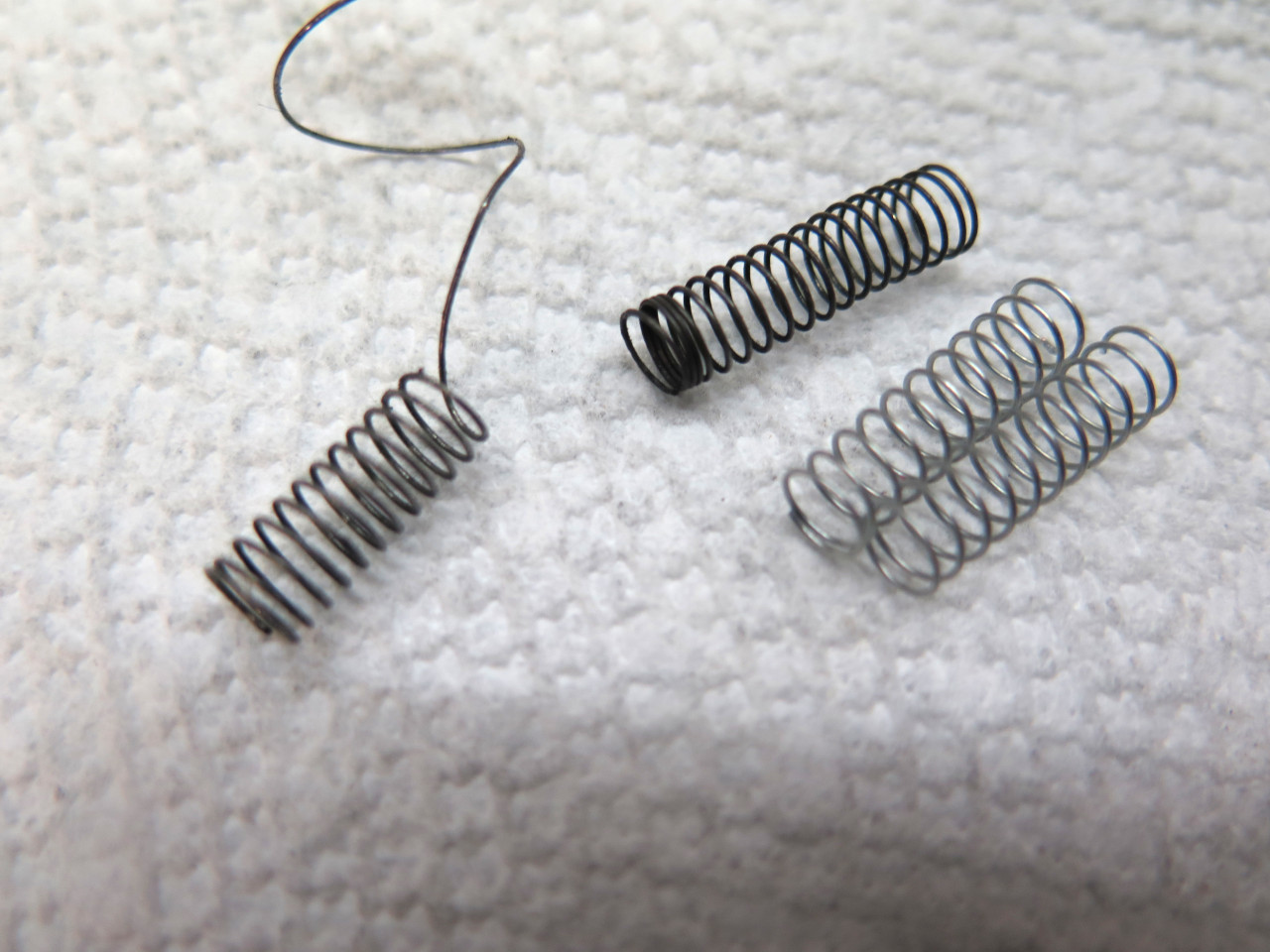
Nothing was a particularly close match. But fortunately, my local
ACE Hardware came through for me. A pretty close match, and
exactly twice too long. I cut it in half and installed the halves,
more carefully this time.

Another trip to the power supply, and this time I was thrilled to hear a very smooth and quiet motor.
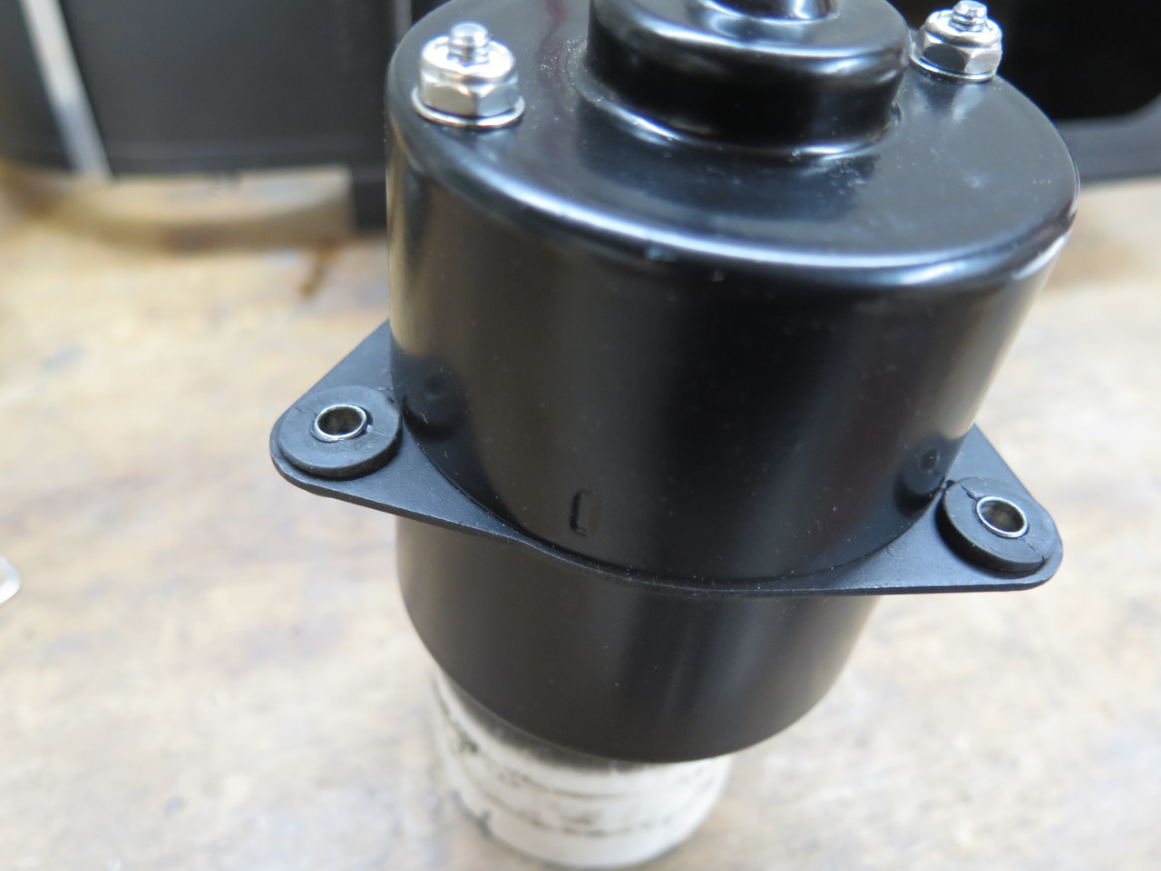
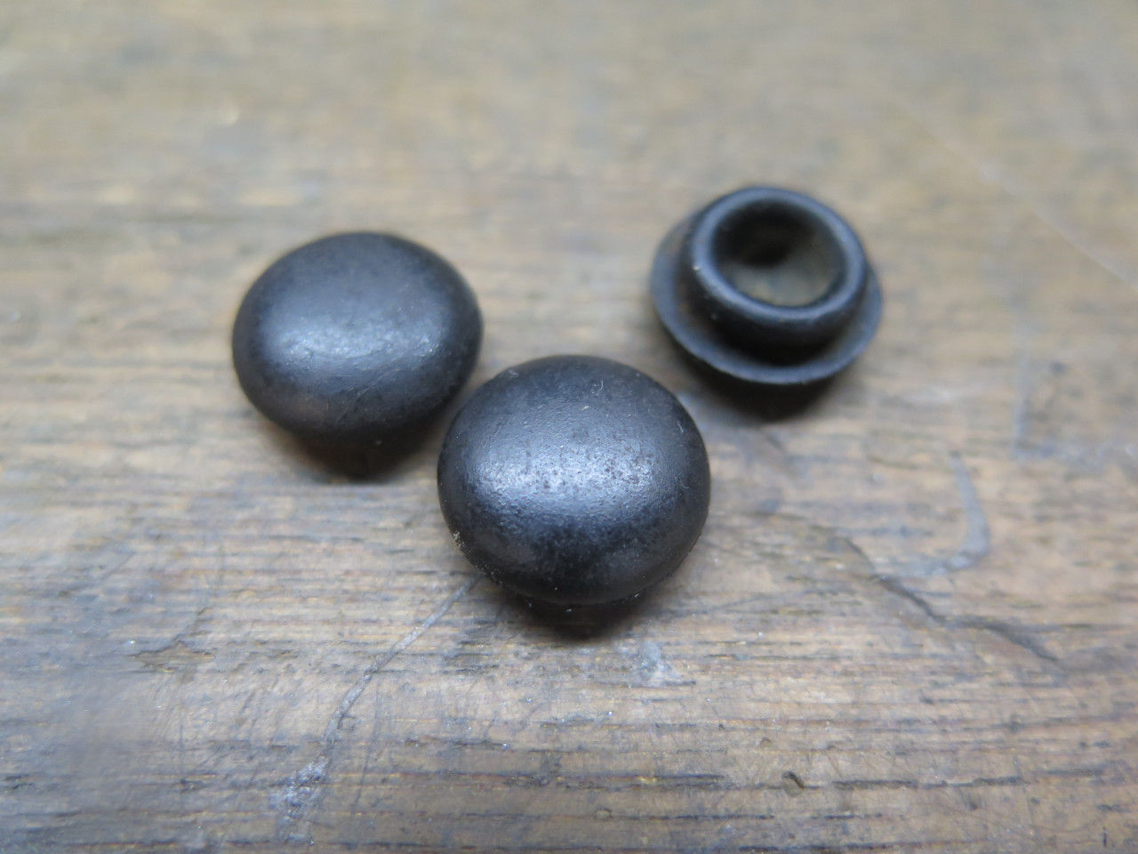
These little grommets serve as a resilient vibration damping mount for the motor. They were good enough to re-use.
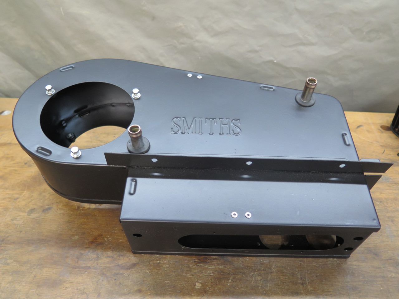
Next was the mounting bracket, and the squirrel cage.

Major components, ready to be co-mingled.
Added the little defrost spigots.
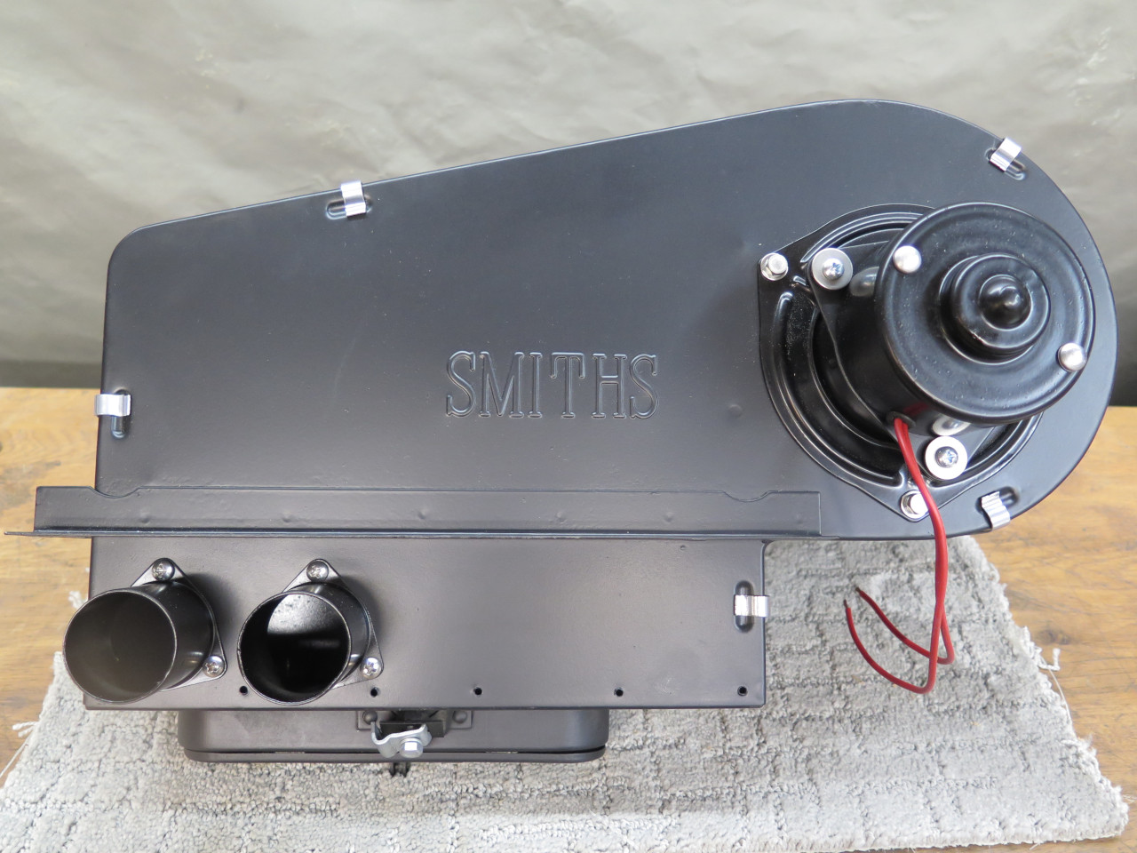
And some little plugs. Not sure what those holes would have been
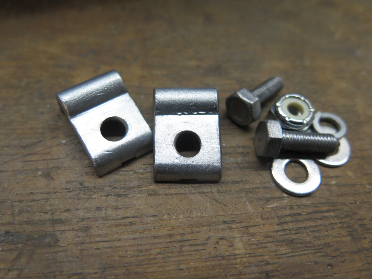
for. Also replated the little control cable housing clamps.
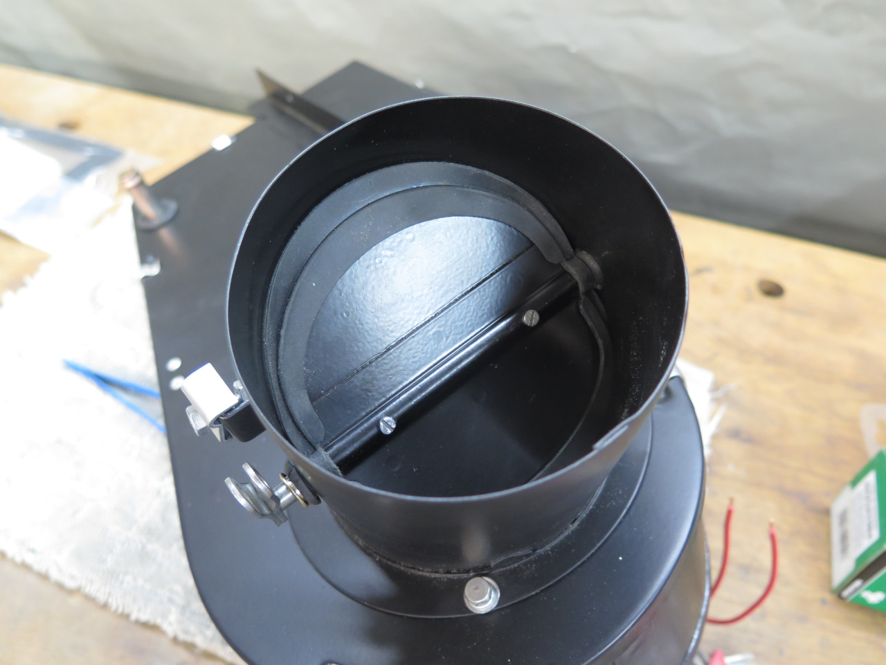
This left just a couple of final details. One was the butterfly
valve in the air inlet. It modulates the amount of outside air
entering the heater. It has a molded rubber seal around it's
perimeter which is still available.
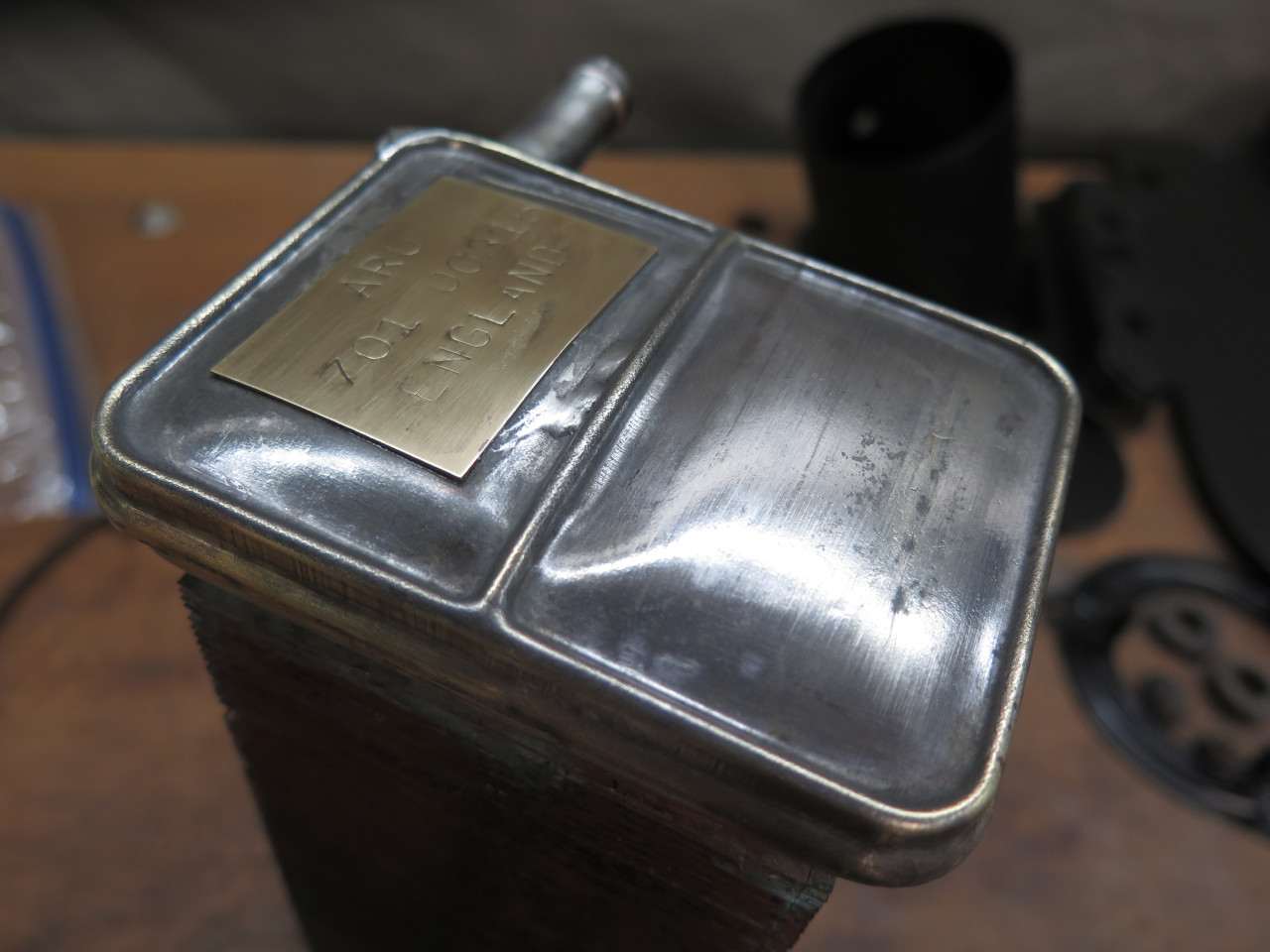
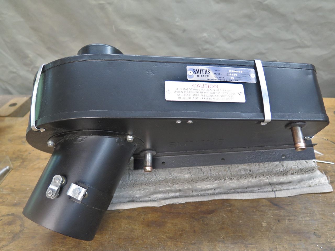
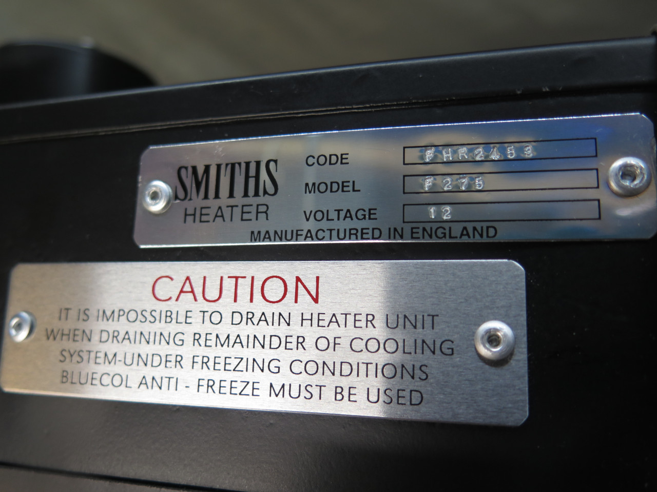
Lastly, a little cosmetic nicety. The little metal ID and caution
plates on the top of my heater were long gone, but reproductions are
available. The number plate proved to be a so-so replica, mainly
in that the bordered fields for the stamped numbers were quite a bit
narrower than the originals. This meant that the original 1/8"
stamped characters would not fit in the space. I opted to move to
the next smaller size, which is 1/16" They fit fine, but look a
little small.
This was a pretty finicky project with some drama thrown in. It
seems like a lot of work for something I'm not sure I'll use much.
I think materials came to less than $50.
Comments to Ed at elhollin1@yahoo.com
To my other MGA pages